EP4028685B1 - Plumbing adapter - Google Patents
Plumbing adapter Download PDFInfo
- Publication number
- EP4028685B1 EP4028685B1 EP20780522.7A EP20780522A EP4028685B1 EP 4028685 B1 EP4028685 B1 EP 4028685B1 EP 20780522 A EP20780522 A EP 20780522A EP 4028685 B1 EP4028685 B1 EP 4028685B1
- Authority
- EP
- European Patent Office
- Prior art keywords
- plumbing
- adapter
- base frame
- interface
- ring
- Prior art date
- Legal status (The legal status is an assumption and is not a legal conclusion. Google has not performed a legal analysis and makes no representation as to the accuracy of the status listed.)
- Active
Links
Images




Classifications
-
- F—MECHANICAL ENGINEERING; LIGHTING; HEATING; WEAPONS; BLASTING
- F16—ENGINEERING ELEMENTS AND UNITS; GENERAL MEASURES FOR PRODUCING AND MAINTAINING EFFECTIVE FUNCTIONING OF MACHINES OR INSTALLATIONS; THERMAL INSULATION IN GENERAL
- F16L—PIPES; JOINTS OR FITTINGS FOR PIPES; SUPPORTS FOR PIPES, CABLES OR PROTECTIVE TUBING; MEANS FOR THERMAL INSULATION IN GENERAL
- F16L27/00—Adjustable joints; Joints allowing movement
- F16L27/08—Adjustable joints; Joints allowing movement allowing adjustment or movement only about the axis of one pipe
- F16L27/0849—Adjustable joints; Joints allowing movement allowing adjustment or movement only about the axis of one pipe the fluid being turned through an angle when passing from one joint element to another
-
- B—PERFORMING OPERATIONS; TRANSPORTING
- B64—AIRCRAFT; AVIATION; COSMONAUTICS
- B64D—EQUIPMENT FOR FITTING IN OR TO AIRCRAFT; FLIGHT SUITS; PARACHUTES; ARRANGEMENT OR MOUNTING OF POWER PLANTS OR PROPULSION TRANSMISSIONS IN AIRCRAFT
- B64D11/00—Passenger or crew accommodation; Flight-deck installations not otherwise provided for
- B64D11/02—Toilet fittings
Definitions
- a plumbing adapter for use in connecting two plumbing interfaces to one another.
- the plumbing adapter is configured to move between multiple positions in order to accommodate any misalignment between the two plumbing interfaces.
- misalignment in plumbing lines may be addressed by using flexible components.
- a flexible rubber or silicone component may be used to bridge the offset/gap connection.
- such components may have connections that provide only limited adaptability. Accordingly, improved plumbing adapters are desirable.
- Background of the invention includes FR-A1-2 307 211 , EP-A1-1 411 219 and GB-A-2 463 036 .
- the present inventors have designed a plumbing adapter that can be used to compensate for misalignment between two plumbing interfaces.
- the plumbing adapter has a base frame supporting an inner ring and an outer ring, wherein the inner ring inner diameter defines a first central longitudinal axis, wherein the outer ring inner diameter defines a second central longitudinal axis, wherein the inner ring and the outer ring are both rotatable within the base frame such that the first central longitudinal axis and the second central longitudinal axis can be moved with respect to one another in order to accommodate for misalignment between the first plumbing interface and the second plumbing interface.
- the inner ring has a wider portion and the outer ring has a wider portion, which allows for eccentricity of the rings with respect to the base frame.
- the inner ring is provided with a raised shoulder that cooperates with the first plumbing interface.
- the base frame may have one or more securement features that cooperate with the second plumbing interface.
- the base frame may have an outer groove that receives an external edge of the outer ring.
- the base frame may also have an inner groove that receives the inner ring.
- At least one gasket seal may be used to help maintain the rings in position with respect to one another and to prevent leakage.
- One or more O-ring seals may also be used.
- the first plumbing interface may be a ball valve of an aircraft waste tank
- the second plumbing interface may be an aircraft service panel
- Embodiments of the present disclosure provide a plumbing adapter that can be used to compensate for misalignment between two plumbing interfaces.
- a first plumbing interface may be mounted such that it is offset from a second plumbing interface to which it should connect. In one example, this may occur in connection with an aircraft waste tank.
- the waste tank typically has a ball valve at its outlet, and the ball valve connects the waste tank to a service panel. If the ball valve and the service panel are not perfectly aligned in the same plane (i.e., they do not share the same central longitudinal axis), the disclosed plumbing adapter may be used in order to compensate for the misalignment.
- the plumbing adapter 10 is shown having non-concentric rings 12, 14.
- the inner ring 12 has a first inner diameter ID1 with a first central longitudinal axis 16 and an outer diameter OD1 with axis 160.
- the axis 160 drawn through OD1 is offset from the first central longitudinal axis 16 of ID1.
- the outer ring 14 has its inner diameter ID2 with a second central longitudinal axis 18 and an outer diameter OD2 with axis 180.
- the axis 180 drawn through OD2 is offset from the second central longitudinal axis 16 of OD1. This is due to the eccentricity of each ring's perimeter, described below.
- Figure 2B These inner and outer diameters of the inner and outer rings are shown in detail by Figure 2B . Whether the inner ring 12 and the outer ring 14 are centered or not centered with respect to one another, the longitudinal axes 16, 18 are offset from one another, as shown by Figure 3 .
- both of the rings 12, 14 are mounted with respect to a base frame 22.
- the base frame 22 may have securement features 24 that allow it to be secured with respect to an aircraft service panel or other plumbing interface.
- the base frame 22 may have an outer groove 26 which is sized and shaped to receive the outer ring 14.
- the outer ring 14 is eccentric, such that there is a first portion 28 of the outer ring 14 that is a wider (defining a wider portion 28) than a second portion 30.
- the base frame 22 may have an inner groove 32 which is sized and shaped to receive the inner ring 12.
- the inner ring 12 is also eccentric. Referring more specifically to the features of the inner ring 12, the inner ring 12 has a raised shoulder 34 defining an interior perimeter 36.
- the interior perimeter 36 is the opening through which fluid will pass from a first plumbing interface to a second plumbing interface.
- the raised shoulder 34 cooperates with or connects to a first plumbing interface in order to create a liquid-tight seal. Movement of the inner ring 12 with respect to the base frame 22 causes movement of the raised shoulder 34.
- the inner ring 12 also has an external flange 38, which sits within the inner groove 32.
- a gasket seal 40 may be provided in order to secure and seal components of the plumbing adapter 10 together.
- the external flange 38 may be eccentric. There may be a first portion 42 of the inner ring 12 that is a wider (defining a wider portion 42) than a second portion 44. This eccentricity means that when the inner ring 12 is rotated with respect to the base frame 22, the central longitudinal axis 16 of the inner ring 12 becomes offset from the central longitudinal axis 18 of the outer ring 14. This moves the cooperation or connection point of the plumbing adapter 10 with respect to the first plumbing interface.
- Movement of the inner ring 12 allows for a certain tolerance to correct for any misalignment between the first and second interfaces. If movement of the inner ring 12 is not sufficient to correct for any misalignment between the plumbing interfaces, the outer ring 14 may also be rotated. The movement of the inner ring 12 and the outer ring 14 may occur in any order, for example, the outer ring 14 may be maneuvered first if desired. This combined movement of both rings 12, 14 can provide added tolerance to maximize the ability to manage a larger offset/misalignment.
- both the inner ring 12 and the outer ring 14 are rotated to the leftmost side of the base frame 22.
- the rings 12, 14 may be rotated around so that the interior perimeter 36 is moved as far as possible to the right. This example shows how the location of the inner perimeter may be altered upon movement of the rings.
- the rings move independently from one another. By rotating both rings, the axis 16 (of ID1) can assume any position normal to the plane of the wider area 28 in the area defined by maximum offset radius.
- Figure 4 shows that the rings 12, 14 may be designed to be rotated in different directions, such that one ring rotates clockwise and another ring rotates counterclockwise.
- Figures 5A-5E show an example of various ring rotation configurations.
- the outer ring 14 has its wider portion 28 opposite from the wider portion 42 of the inner ring 12. This helps the rings align.
- Figures 5B-5E the outer ring 14 is not moved, but the inner ring 12 is being rotated clockwise.
- FIG. 6 shows a side cross-sectional view of the base frame 22, the inner ring 12, and the outer ring 14 all secured in place with a V-band clamp 50.
- external edges of each of the base frame 22 and the outer ring 14 are shaped to cooperate so that they can fit within a V-seat 52 of the band clamp 50.
- the V-seat 52 of the band clamp 50 would be tightened so that it clamps against the flanges.
- the force perpendicular to the V- profile will sandwich the components together, with gasket 40 providing additional resistance.
- the outer groove 26 of the base frame 22 receives external edge 54 of the outer ring 14.
- the V-band clamp 50 secures it in place with respect to the base frame 22.
- Figure 6 also shows the presence of gasket seal 40. Once the V-band clamp 50 is positioned in place, its pressure secures the inner ring 12 in place, due to presence of the gasket seal 40.
- FIG. 7 illustrates that in addition to gasket seal, one or more O rings 60 may be used in order to seal the fluid exposed inside the plumbing adapter 10 to the ambient environment.
- Figure 8 illustrates a plumbing adapter 10 mounted with respect to a first plumbing interface, which, in this figure is a waste tank ball valve 62.
- the base frame 22 of the plumbing adapter 10 is mounted with respect to a second plumbing interface, which, in this figure is an aircraft service panel 64.
Landscapes
- Engineering & Computer Science (AREA)
- General Engineering & Computer Science (AREA)
- Mechanical Engineering (AREA)
- Aviation & Aerospace Engineering (AREA)
- Flanged Joints, Insulating Joints, And Other Joints (AREA)
- Gasket Seals (AREA)
Description
- This application claims the benefit of
U.S. Provisional Application Serial No. 62/898,750, filed September 11, 2019 - According to certain embodiments of this disclosure, there is provided a plumbing adapter for use in connecting two plumbing interfaces to one another. The plumbing adapter is configured to move between multiple positions in order to accommodate any misalignment between the two plumbing interfaces.
- Commonly, misalignment in plumbing lines may be addressed by using flexible components. For example, if a first plumbing interface is mounted such that it is offset from a corresponding plumbing interface to which it should connect, a flexible rubber or silicone component may be used to bridge the offset/gap connection. However, such components may have connections that provide only limited adaptability. Accordingly, improved plumbing adapters are desirable. Background of the invention includes
FR-A1-2 307 211 EP-A1-1 411 219 andGB-A-2 463 036 - Accordingly, the present inventors have designed a plumbing adapter that can be used to compensate for misalignment between two plumbing interfaces.
- The present invention is defined by the independent claim. Advantageous features are defined in the dependent claims.
- In one example, the plumbing adapter has a base frame supporting an inner ring and an outer ring, wherein the inner ring inner diameter defines a first central longitudinal axis, wherein the outer ring inner diameter defines a second central longitudinal axis, wherein the inner ring and the outer ring are both rotatable within the base frame such that the first central longitudinal axis and the second central longitudinal axis can be moved with respect to one another in order to accommodate for misalignment between the first plumbing interface and the second plumbing interface. The inner ring has a wider portion and the outer ring has a wider portion, which allows for eccentricity of the rings with respect to the base frame. The inner ring is provided with a raised shoulder that cooperates with the first plumbing interface. The base frame may have one or more securement features that cooperate with the second plumbing interface.
- In a specific example, the base frame may have an outer groove that receives an external edge of the outer ring. The base frame may also have an inner groove that receives the inner ring. At least one gasket seal may be used to help maintain the rings in position with respect to one another and to prevent leakage. One or more O-ring seals may also be used.
- In another specific example, the first plumbing interface may be a ball valve of an aircraft waste tank, and the second plumbing interface may be an aircraft service panel.
- Embodiments of the invention covered by this patent are defined by the claims below, not this summary. This summary is a high-level overview of various aspects of the invention and introduces some of the concepts that are further described in the Detailed Description section below. This summary is not intended to identify key or essential features of the claimed subject matter, nor is it intended to be used in isolation to determine the scope of the claimed subject matter. The subject matter should be understood by reference to appropriate portions of the entire specification of this patent, any or all drawings and each claim.
-
-
Figure 1 shows a side perspective view of one embodiment of a plumbing adapter. -
Figure 2A shows an exploded perspective view of the plumbing adapter ofFigure 1 . -
Figure 2B shows a close up view of the inner and outer diameters of the inner and outer rings. -
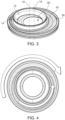
Figure 3 shows a side perspective view of the plumbing adapter ofFigure 1 with the inner ring rotated. -
Figure 4 shows a top plan view of a plumbing adapter. -
Figures 5A-5E show top plan views of a plumbing adapter with the inner ring being rotated around the base frame. -
Figure 6 shows a side cross-sectional view of a plumbing adapter edge with a V-band clamp in place. -
Figure 7 shows a side cross-sectional view of an optional position of an O-ring seal in a plumbing adapter. -
Figure 8 shows a side plan view of a plumbing adapter used to connect first and second plumbing interfaces. - Embodiments of the present disclosure provide a plumbing adapter that can be used to compensate for misalignment between two plumbing interfaces. In a specific example, a first plumbing interface may be mounted such that it is offset from a second plumbing interface to which it should connect. In one example, this may occur in connection with an aircraft waste tank. The waste tank typically has a ball valve at its outlet, and the ball valve connects the waste tank to a service panel. If the ball valve and the service panel are not perfectly aligned in the same plane (i.e., they do not share the same central longitudinal axis), the disclosed plumbing adapter may be used in order to compensate for the misalignment.
- Referring now to
Figures 1-5 , theplumbing adapter 10 is shown havingnon-concentric rings inner ring 12 has a first inner diameter ID1 with a first centrallongitudinal axis 16 and an outer diameter OD1 withaxis 160. Theaxis 160 drawn through OD1 is offset from the first centrallongitudinal axis 16 of ID1. Theouter ring 14 has its inner diameter ID2 with a second centrallongitudinal axis 18 and an outer diameter OD2 withaxis 180. Theaxis 180 drawn through OD2 is offset from the second centrallongitudinal axis 16 of OD1. This is due to the eccentricity of each ring's perimeter, described below. These inner and outer diameters of the inner and outer rings are shown in detail byFigure 2B . Whether theinner ring 12 and theouter ring 14 are centered or not centered with respect to one another, thelongitudinal axes Figure 3 . - As shown by
Figure 2 , both of therings base frame 22. Thebase frame 22 may have securement features 24 that allow it to be secured with respect to an aircraft service panel or other plumbing interface. Thebase frame 22 may have anouter groove 26 which is sized and shaped to receive theouter ring 14. As shown, theouter ring 14 is eccentric, such that there is afirst portion 28 of theouter ring 14 that is a wider (defining a wider portion 28) than asecond portion 30. Thebase frame 22 may have aninner groove 32 which is sized and shaped to receive theinner ring 12. As shown, theinner ring 12 is also eccentric. Referring more specifically to the features of theinner ring 12, theinner ring 12 has a raisedshoulder 34 defining aninterior perimeter 36. Theinterior perimeter 36 is the opening through which fluid will pass from a first plumbing interface to a second plumbing interface. The raisedshoulder 34 cooperates with or connects to a first plumbing interface in order to create a liquid-tight seal. Movement of theinner ring 12 with respect to thebase frame 22 causes movement of the raisedshoulder 34. - The
inner ring 12 also has anexternal flange 38, which sits within theinner groove 32. Agasket seal 40 may be provided in order to secure and seal components of theplumbing adapter 10 together. Theexternal flange 38 may be eccentric. There may be afirst portion 42 of theinner ring 12 that is a wider (defining a wider portion 42) than a second portion 44. This eccentricity means that when theinner ring 12 is rotated with respect to thebase frame 22, the centrallongitudinal axis 16 of theinner ring 12 becomes offset from the centrallongitudinal axis 18 of theouter ring 14. This moves the cooperation or connection point of theplumbing adapter 10 with respect to the first plumbing interface. - Movement of the
inner ring 12 allows for a certain tolerance to correct for any misalignment between the first and second interfaces. If movement of theinner ring 12 is not sufficient to correct for any misalignment between the plumbing interfaces, theouter ring 14 may also be rotated. The movement of theinner ring 12 and theouter ring 14 may occur in any order, for example, theouter ring 14 may be maneuvered first if desired. This combined movement of bothrings - In
Figure 3 , both theinner ring 12 and theouter ring 14 are rotated to the leftmost side of thebase frame 22. This means that thewider portion 28 of theouter ring 14 and thewider portion 42 of theinner ring 12 are shown at the right-most side of thebase frame 22. This pushes theinterior perimeter 36 as far as possible to the left. It should be understood that therings interior perimeter 36 is moved as far as possible to the right. This example shows how the location of the inner perimeter may be altered upon movement of the rings. - The rings move independently from one another. By rotating both rings, the axis 16 (of ID1) can assume any position normal to the plane of the
wider area 28 in the area defined by maximum offset radius. -
Figure 4 shows that therings -
Figures 5A-5E show an example of various ring rotation configurations. InFigure 5A , theouter ring 14 has itswider portion 28 opposite from thewider portion 42 of theinner ring 12. This helps the rings align. InFigures 5B-5E , theouter ring 14 is not moved, but theinner ring 12 is being rotated clockwise. -
Figure 6 shows a side cross-sectional view of thebase frame 22, theinner ring 12, and theouter ring 14 all secured in place with a V-band clamp 50. As shown, external edges of each of thebase frame 22 and theouter ring 14 are shaped to cooperate so that they can fit within a V-seat 52 of theband clamp 50. In use, the V-seat 52 of theband clamp 50 would be tightened so that it clamps against the flanges. By tightening the V-Band 50, the force perpendicular to the V- profile will sandwich the components together, withgasket 40 providing additional resistance. - As shown, the
outer groove 26 of thebase frame 22 receivesexternal edge 54 of theouter ring 14. Once theouter ring 14 has been positioned as desired, the V-band clamp 50 secures it in place with respect to thebase frame 22.Figure 6 also shows the presence ofgasket seal 40. Once the V-band clamp 50 is positioned in place, its pressure secures theinner ring 12 in place, due to presence of thegasket seal 40. -
Figure 7 illustrates that in addition to gasket seal, one or more O rings 60 may be used in order to seal the fluid exposed inside theplumbing adapter 10 to the ambient environment. -
Figure 8 illustrates aplumbing adapter 10 mounted with respect to a first plumbing interface, which, in this figure is a wastetank ball valve 62. Thebase frame 22 of theplumbing adapter 10 is mounted with respect to a second plumbing interface, which, in this figure is anaircraft service panel 64. - The subject matter of certain embodiments of this disclosure is described with specificity to meet statutory requirements, but this description is not necessarily intended to limit the scope of the claims.
- It should be understood that different arrangements of the components depicted in the drawings or described above, as well as components and steps not shown or described are possible. Similarly, some features and sub-combinations are useful and may be employed without reference to other features and sub-combinations. Embodiments of the invention have been described for illustrative and not restrictive purposes, and alternative embodiments will become apparent to readers of this patent. Accordingly, the present invention is not limited to the embodiments described above or depicted in the drawings, and various embodiments and modifications may be made without departing from the scope of the claims below.
Claims (7)
- A plumbing adapter for use between a first plumbing interface and a second plumbing interface that are misaligned, the plumbing adapter (10) comprising:a base frame (22) supporting an inner ring (12) and an outer ring (14),wherein the inner ring (12) inner diameter defines a first central longitudinal axis (16),wherein the outer ring (14) inner diameter defines a second central longitudinal axis (18),wherein the inner ring (12) and the outer ring (14) are both rotatable within the base frame such that the first central longitudinal axis (16) and the second central longitudinal axis (18) can be moved with respect to one another in order to accommodate for misalignment between the first plumbing interface and the second plumbing interface,wherein the inner ring (14) comprises a wider portion (42) and wherein the outer ring comprises a wider portion, wherein the wider portions (42, 28) of the inner and outer rings allow for eccentricity of the rings (12, 14) with respect to the base frame,wherein the inner ring (14) comprises a raised shoulder (34) for cooperating with the first plumbing interface, andcharacterized in that a position of the first longitudinal axis (16) may be controlled by rotating both the inner ring (14) and the outer ring (12) independently from one another relative to the base frame (22).
- The plumbing adapter of claim 1, wherein the base frame comprises one or more securement features (24) that cooperate for cooperating with the second plumbing interface.
- The plumbing adapter of claim 1, wherein the base frame comprises an outer groove (26) that receives an external edge (54) of the outer ring (14).
- The plumbing adapter of claim 1, wherein the base frame comprises an inner groove (32) that receives the inner ring (12).
- The plumbing adapter of claim 1, further comprising at least one gasket seal (40).
- The plumbing adapter of claim 1, further comprising one or more O-ring seals (60).
- A plumbing system comprising the plumbing adapter of claim 1, the first plumbing interface, and the second plumbing interface, wherein the first plumbing interface comprises a ball valve (62) for ef an aircraft waste tank, and wherein the second plumbing interface comprises a service panel (64).
Applications Claiming Priority (2)
| Application Number | Priority Date | Filing Date | Title |
|---|---|---|---|
| US201962898750P | 2019-09-11 | 2019-09-11 | |
| PCT/US2020/050469 WO2021050926A1 (en) | 2019-09-11 | 2020-09-11 | Plumbing adapter |
Publications (2)
| Publication Number | Publication Date |
|---|---|
| EP4028685A1 EP4028685A1 (en) | 2022-07-20 |
| EP4028685B1 true EP4028685B1 (en) | 2024-12-04 |
Family
ID=72644995
Family Applications (1)
| Application Number | Title | Priority Date | Filing Date |
|---|---|---|---|
| EP20780522.7A Active EP4028685B1 (en) | 2019-09-11 | 2020-09-11 | Plumbing adapter |
Country Status (3)
| Country | Link |
|---|---|
| US (1) | US12135101B2 (en) |
| EP (1) | EP4028685B1 (en) |
| WO (1) | WO2021050926A1 (en) |
Families Citing this family (2)
| Publication number | Priority date | Publication date | Assignee | Title |
|---|---|---|---|---|
| US11610670B1 (en) | 2019-04-25 | 2023-03-21 | Cvs Pharmacy, Inc. | System and method of dynamically generating work assignments |
| CN116867990A (en) | 2021-02-23 | 2023-10-10 | 玛格太空工业有限责任公司 | Corrugated pipe design to absorb misalignment |
Family Cites Families (5)
| Publication number | Priority date | Publication date | Assignee | Title |
|---|---|---|---|---|
| US1304979A (en) * | 1919-05-27 | hirshstein | ||
| HU169597B (en) * | 1975-04-09 | 1976-12-28 | ||
| DE10248816A1 (en) * | 2002-10-19 | 2004-11-11 | Audi Ag | Connection and adjustment device |
| GB2463936B (en) * | 2008-10-02 | 2012-04-18 | Kohler Mira Ltd | Fluid connector |
| WO2014081912A2 (en) | 2012-11-21 | 2014-05-30 | Mag Aerospace Industries, Inc. | Toilet concepts |
-
2020
- 2020-09-11 WO PCT/US2020/050469 patent/WO2021050926A1/en not_active Ceased
- 2020-09-11 EP EP20780522.7A patent/EP4028685B1/en active Active
- 2020-09-11 US US17/639,995 patent/US12135101B2/en active Active
Also Published As
| Publication number | Publication date |
|---|---|
| US12135101B2 (en) | 2024-11-05 |
| EP4028685A1 (en) | 2022-07-20 |
| US20220325831A1 (en) | 2022-10-13 |
| WO2021050926A1 (en) | 2021-03-18 |
Similar Documents
| Publication | Publication Date | Title |
|---|---|---|
| CA2630281C (en) | Aircraft fuel pipe coupling | |
| US20130026751A1 (en) | Pipe connector | |
| US7717473B1 (en) | Dual walled transfer tube | |
| GB2171770A (en) | Clamped swivel coupling to a fluid container | |
| US12135101B2 (en) | Plumbing adapter | |
| US4886301A (en) | Quick disconnect with a position compensating seal | |
| US20250224056A1 (en) | System for circulating fluid between at least two hollow bodies or housings | |
| US10975862B2 (en) | Valve adapter connection assembly | |
| EP4177507B1 (en) | Pipeline alignment structure and alignment pipeline thereof | |
| US20070278786A1 (en) | Fluid Coupling System | |
| CN102418821A (en) | hose connecting sleeve | |
| US20100209198A1 (en) | Modular hot stab with improved connection flange | |
| US20170002964A1 (en) | High pressure fluid swivel | |
| JPH02502037A (en) | concentric flexible pipe fittings | |
| US20100187811A1 (en) | Rotatable coupling | |
| GB2463936A (en) | A fluid connector for a mixing valve which compensates for misalignment of supply pipework | |
| EP3652070B1 (en) | Fuel tank communication systems | |
| CN214425392U (en) | 360-degree rotatable bidirectional telescopic pipe connector | |
| US11585470B2 (en) | Formed pipe end-section of a pipeline and pipe screw-connection | |
| GB2055167A (en) | Angularly adaptable seal | |
| US20220213992A1 (en) | Arrangement | |
| JP4616436B2 (en) | Fluid injection device | |
| US10876670B2 (en) | Blind flange and method of installing same for isolating hazardous energy within a facility | |
| CN213655145U (en) | Horizontal two-stage centrifugal pump | |
| CA3042139C (en) | Device for connecting pipe ends of double-walled pipes |
Legal Events
| Date | Code | Title | Description |
|---|---|---|---|
| STAA | Information on the status of an ep patent application or granted ep patent |
Free format text: STATUS: UNKNOWN |
|
| STAA | Information on the status of an ep patent application or granted ep patent |
Free format text: STATUS: THE INTERNATIONAL PUBLICATION HAS BEEN MADE |
|
| PUAI | Public reference made under article 153(3) epc to a published international application that has entered the european phase |
Free format text: ORIGINAL CODE: 0009012 |
|
| STAA | Information on the status of an ep patent application or granted ep patent |
Free format text: STATUS: REQUEST FOR EXAMINATION WAS MADE |
|
| 17P | Request for examination filed |
Effective date: 20220408 |
|
| AK | Designated contracting states |
Kind code of ref document: A1 Designated state(s): AL AT BE BG CH CY CZ DE DK EE ES FI FR GB GR HR HU IE IS IT LI LT LU LV MC MK MT NL NO PL PT RO RS SE SI SK SM TR |
|
| DAV | Request for validation of the european patent (deleted) | ||
| DAX | Request for extension of the european patent (deleted) | ||
| STAA | Information on the status of an ep patent application or granted ep patent |
Free format text: STATUS: EXAMINATION IS IN PROGRESS |
|
| 17Q | First examination report despatched |
Effective date: 20240112 |
|
| GRAP | Despatch of communication of intention to grant a patent |
Free format text: ORIGINAL CODE: EPIDOSNIGR1 |
|
| STAA | Information on the status of an ep patent application or granted ep patent |
Free format text: STATUS: GRANT OF PATENT IS INTENDED |
|
| INTG | Intention to grant announced |
Effective date: 20240722 |
|
| GRAS | Grant fee paid |
Free format text: ORIGINAL CODE: EPIDOSNIGR3 |
|
| GRAA | (expected) grant |
Free format text: ORIGINAL CODE: 0009210 |
|
| STAA | Information on the status of an ep patent application or granted ep patent |
Free format text: STATUS: THE PATENT HAS BEEN GRANTED |
|
| AK | Designated contracting states |
Kind code of ref document: B1 Designated state(s): AL AT BE BG CH CY CZ DE DK EE ES FI FR GB GR HR HU IE IS IT LI LT LU LV MC MK MT NL NO PL PT RO RS SE SI SK SM TR |
|
| REG | Reference to a national code |
Ref country code: CH Ref legal event code: EP |
|
| REG | Reference to a national code |
Ref country code: DE Ref legal event code: R096 Ref document number: 602020042566 Country of ref document: DE |
|
| REG | Reference to a national code |
Ref country code: IE Ref legal event code: FG4D |
|
| REG | Reference to a national code |
Ref country code: LT Ref legal event code: MG9D |
|
| REG | Reference to a national code |
Ref country code: NL Ref legal event code: MP Effective date: 20241204 |
|
| PG25 | Lapsed in a contracting state [announced via postgrant information from national office to epo] |
Ref country code: HR Free format text: LAPSE BECAUSE OF FAILURE TO SUBMIT A TRANSLATION OF THE DESCRIPTION OR TO PAY THE FEE WITHIN THE PRESCRIBED TIME-LIMIT Effective date: 20241204 |
|
| PG25 | Lapsed in a contracting state [announced via postgrant information from national office to epo] |
Ref country code: FI Free format text: LAPSE BECAUSE OF FAILURE TO SUBMIT A TRANSLATION OF THE DESCRIPTION OR TO PAY THE FEE WITHIN THE PRESCRIBED TIME-LIMIT Effective date: 20241204 |
|
| PG25 | Lapsed in a contracting state [announced via postgrant information from national office to epo] |
Ref country code: BG Free format text: LAPSE BECAUSE OF FAILURE TO SUBMIT A TRANSLATION OF THE DESCRIPTION OR TO PAY THE FEE WITHIN THE PRESCRIBED TIME-LIMIT Effective date: 20241204 |
|
| PG25 | Lapsed in a contracting state [announced via postgrant information from national office to epo] |
Ref country code: ES Free format text: LAPSE BECAUSE OF FAILURE TO SUBMIT A TRANSLATION OF THE DESCRIPTION OR TO PAY THE FEE WITHIN THE PRESCRIBED TIME-LIMIT Effective date: 20241204 |
|
| PG25 | Lapsed in a contracting state [announced via postgrant information from national office to epo] |
Ref country code: NO Free format text: LAPSE BECAUSE OF FAILURE TO SUBMIT A TRANSLATION OF THE DESCRIPTION OR TO PAY THE FEE WITHIN THE PRESCRIBED TIME-LIMIT Effective date: 20250304 |
|
| PG25 | Lapsed in a contracting state [announced via postgrant information from national office to epo] |
Ref country code: GR Free format text: LAPSE BECAUSE OF FAILURE TO SUBMIT A TRANSLATION OF THE DESCRIPTION OR TO PAY THE FEE WITHIN THE PRESCRIBED TIME-LIMIT Effective date: 20250305 Ref country code: LV Free format text: LAPSE BECAUSE OF FAILURE TO SUBMIT A TRANSLATION OF THE DESCRIPTION OR TO PAY THE FEE WITHIN THE PRESCRIBED TIME-LIMIT Effective date: 20241204 |
|
| PG25 | Lapsed in a contracting state [announced via postgrant information from national office to epo] |
Ref country code: RS Free format text: LAPSE BECAUSE OF FAILURE TO SUBMIT A TRANSLATION OF THE DESCRIPTION OR TO PAY THE FEE WITHIN THE PRESCRIBED TIME-LIMIT Effective date: 20250304 |
|
| PG25 | Lapsed in a contracting state [announced via postgrant information from national office to epo] |
Ref country code: NL Free format text: LAPSE BECAUSE OF FAILURE TO SUBMIT A TRANSLATION OF THE DESCRIPTION OR TO PAY THE FEE WITHIN THE PRESCRIBED TIME-LIMIT Effective date: 20241204 |
|
| REG | Reference to a national code |
Ref country code: AT Ref legal event code: MK05 Ref document number: 1748501 Country of ref document: AT Kind code of ref document: T Effective date: 20241204 |
|
| PG25 | Lapsed in a contracting state [announced via postgrant information from national office to epo] |
Ref country code: SM Free format text: LAPSE BECAUSE OF FAILURE TO SUBMIT A TRANSLATION OF THE DESCRIPTION OR TO PAY THE FEE WITHIN THE PRESCRIBED TIME-LIMIT Effective date: 20241204 |
|
| PG25 | Lapsed in a contracting state [announced via postgrant information from national office to epo] |
Ref country code: PL Free format text: LAPSE BECAUSE OF FAILURE TO SUBMIT A TRANSLATION OF THE DESCRIPTION OR TO PAY THE FEE WITHIN THE PRESCRIBED TIME-LIMIT Effective date: 20241204 |
|
| PG25 | Lapsed in a contracting state [announced via postgrant information from national office to epo] |
Ref country code: IS Free format text: LAPSE BECAUSE OF FAILURE TO SUBMIT A TRANSLATION OF THE DESCRIPTION OR TO PAY THE FEE WITHIN THE PRESCRIBED TIME-LIMIT Effective date: 20250404 |
|
| PG25 | Lapsed in a contracting state [announced via postgrant information from national office to epo] |
Ref country code: PT Free format text: LAPSE BECAUSE OF FAILURE TO SUBMIT A TRANSLATION OF THE DESCRIPTION OR TO PAY THE FEE WITHIN THE PRESCRIBED TIME-LIMIT Effective date: 20250404 |
|
| PG25 | Lapsed in a contracting state [announced via postgrant information from national office to epo] |
Ref country code: EE Free format text: LAPSE BECAUSE OF FAILURE TO SUBMIT A TRANSLATION OF THE DESCRIPTION OR TO PAY THE FEE WITHIN THE PRESCRIBED TIME-LIMIT Effective date: 20241204 |
|
| PG25 | Lapsed in a contracting state [announced via postgrant information from national office to epo] |
Ref country code: AT Free format text: LAPSE BECAUSE OF FAILURE TO SUBMIT A TRANSLATION OF THE DESCRIPTION OR TO PAY THE FEE WITHIN THE PRESCRIBED TIME-LIMIT Effective date: 20241204 Ref country code: RO Free format text: LAPSE BECAUSE OF FAILURE TO SUBMIT A TRANSLATION OF THE DESCRIPTION OR TO PAY THE FEE WITHIN THE PRESCRIBED TIME-LIMIT Effective date: 20241204 |
|
| PG25 | Lapsed in a contracting state [announced via postgrant information from national office to epo] |
Ref country code: SK Free format text: LAPSE BECAUSE OF FAILURE TO SUBMIT A TRANSLATION OF THE DESCRIPTION OR TO PAY THE FEE WITHIN THE PRESCRIBED TIME-LIMIT Effective date: 20241204 |
|
| PG25 | Lapsed in a contracting state [announced via postgrant information from national office to epo] |
Ref country code: CZ Free format text: LAPSE BECAUSE OF FAILURE TO SUBMIT A TRANSLATION OF THE DESCRIPTION OR TO PAY THE FEE WITHIN THE PRESCRIBED TIME-LIMIT Effective date: 20241204 |
|
| PG25 | Lapsed in a contracting state [announced via postgrant information from national office to epo] |
Ref country code: IT Free format text: LAPSE BECAUSE OF FAILURE TO SUBMIT A TRANSLATION OF THE DESCRIPTION OR TO PAY THE FEE WITHIN THE PRESCRIBED TIME-LIMIT Effective date: 20241204 |
|
| REG | Reference to a national code |
Ref country code: DE Ref legal event code: R097 Ref document number: 602020042566 Country of ref document: DE |
|
| PG25 | Lapsed in a contracting state [announced via postgrant information from national office to epo] |
Ref country code: SE Free format text: LAPSE BECAUSE OF FAILURE TO SUBMIT A TRANSLATION OF THE DESCRIPTION OR TO PAY THE FEE WITHIN THE PRESCRIBED TIME-LIMIT Effective date: 20241204 |
|
| PG25 | Lapsed in a contracting state [announced via postgrant information from national office to epo] |
Ref country code: DK Free format text: LAPSE BECAUSE OF FAILURE TO SUBMIT A TRANSLATION OF THE DESCRIPTION OR TO PAY THE FEE WITHIN THE PRESCRIBED TIME-LIMIT Effective date: 20241204 |
|
| PGFP | Annual fee paid to national office [announced via postgrant information from national office to epo] |
Ref country code: DE Payment date: 20250919 Year of fee payment: 6 |
|
| PLBE | No opposition filed within time limit |
Free format text: ORIGINAL CODE: 0009261 |
|
| STAA | Information on the status of an ep patent application or granted ep patent |
Free format text: STATUS: NO OPPOSITION FILED WITHIN TIME LIMIT |
|
| REG | Reference to a national code |
Ref country code: CH Ref legal event code: L10 Free format text: ST27 STATUS EVENT CODE: U-0-0-L10-L00 (AS PROVIDED BY THE NATIONAL OFFICE) Effective date: 20251015 |
|
| PGFP | Annual fee paid to national office [announced via postgrant information from national office to epo] |
Ref country code: GB Payment date: 20250923 Year of fee payment: 6 |
|
| PGFP | Annual fee paid to national office [announced via postgrant information from national office to epo] |
Ref country code: FR Payment date: 20250923 Year of fee payment: 6 |
|
| 26N | No opposition filed |
Effective date: 20250905 |
|
| REG | Reference to a national code |
Ref country code: CH Ref legal event code: H13 Free format text: ST27 STATUS EVENT CODE: U-0-0-H10-H13 (AS PROVIDED BY THE NATIONAL OFFICE) Effective date: 20260504 |