EP4028334B1 - Straw lid assembly - Google Patents
Straw lid assembly Download PDFInfo
- Publication number
- EP4028334B1 EP4028334B1 EP20862671.3A EP20862671A EP4028334B1 EP 4028334 B1 EP4028334 B1 EP 4028334B1 EP 20862671 A EP20862671 A EP 20862671A EP 4028334 B1 EP4028334 B1 EP 4028334B1
- Authority
- EP
- European Patent Office
- Prior art keywords
- spout
- cap
- passage
- valve member
- valve assembly
- Prior art date
- Legal status (The legal status is an assumption and is not a legal conclusion. Google has not performed a legal analysis and makes no representation as to the accuracy of the status listed.)
- Active
Links
Images




Classifications
-
- B—PERFORMING OPERATIONS; TRANSPORTING
- B65—CONVEYING; PACKING; STORING; HANDLING THIN OR FILAMENTARY MATERIAL
- B65D—CONTAINERS FOR STORAGE OR TRANSPORT OF ARTICLES OR MATERIALS, e.g. BAGS, BARRELS, BOTTLES, BOXES, CANS, CARTONS, CRATES, DRUMS, JARS, TANKS, HOPPERS, FORWARDING CONTAINERS; ACCESSORIES, CLOSURES, OR FITTINGS THEREFOR; PACKAGING ELEMENTS; PACKAGES
- B65D43/00—Lids or covers for rigid or semi-rigid containers
- B65D43/02—Removable lids or covers
- B65D43/0202—Removable lids or covers without integral tamper element
- B65D43/0225—Removable lids or covers without integral tamper element secured by rotation
- B65D43/0231—Removable lids or covers without integral tamper element secured by rotation only on the outside, or a part turned to the outside, of the mouth of the container
-
- B—PERFORMING OPERATIONS; TRANSPORTING
- B65—CONVEYING; PACKING; STORING; HANDLING THIN OR FILAMENTARY MATERIAL
- B65D—CONTAINERS FOR STORAGE OR TRANSPORT OF ARTICLES OR MATERIALS, e.g. BAGS, BARRELS, BOTTLES, BOXES, CANS, CARTONS, CRATES, DRUMS, JARS, TANKS, HOPPERS, FORWARDING CONTAINERS; ACCESSORIES, CLOSURES, OR FITTINGS THEREFOR; PACKAGING ELEMENTS; PACKAGES
- B65D47/00—Closures with filling and discharging, or with discharging, devices
- B65D47/04—Closures with discharging devices other than pumps
- B65D47/06—Closures with discharging devices other than pumps with pouring spouts or tubes; with discharge nozzles or passages
- B65D47/065—Closures with discharging devices other than pumps with pouring spouts or tubes; with discharge nozzles or passages with hinged, foldable or pivotable spouts
-
- B—PERFORMING OPERATIONS; TRANSPORTING
- B65—CONVEYING; PACKING; STORING; HANDLING THIN OR FILAMENTARY MATERIAL
- B65D—CONTAINERS FOR STORAGE OR TRANSPORT OF ARTICLES OR MATERIALS, e.g. BAGS, BARRELS, BOTTLES, BOXES, CANS, CARTONS, CRATES, DRUMS, JARS, TANKS, HOPPERS, FORWARDING CONTAINERS; ACCESSORIES, CLOSURES, OR FITTINGS THEREFOR; PACKAGING ELEMENTS; PACKAGES
- B65D47/00—Closures with filling and discharging, or with discharging, devices
- B65D47/04—Closures with discharging devices other than pumps
- B65D47/20—Closures with discharging devices other than pumps comprising hand-operated members for controlling discharge
-
- B—PERFORMING OPERATIONS; TRANSPORTING
- B65—CONVEYING; PACKING; STORING; HANDLING THIN OR FILAMENTARY MATERIAL
- B65D—CONTAINERS FOR STORAGE OR TRANSPORT OF ARTICLES OR MATERIALS, e.g. BAGS, BARRELS, BOTTLES, BOXES, CANS, CARTONS, CRATES, DRUMS, JARS, TANKS, HOPPERS, FORWARDING CONTAINERS; ACCESSORIES, CLOSURES, OR FITTINGS THEREFOR; PACKAGING ELEMENTS; PACKAGES
- B65D47/00—Closures with filling and discharging, or with discharging, devices
- B65D47/04—Closures with discharging devices other than pumps
- B65D47/32—Closures with discharging devices other than pumps with means for venting
-
- A—HUMAN NECESSITIES
- A47—FURNITURE; DOMESTIC ARTICLES OR APPLIANCES; COFFEE MILLS; SPICE MILLS; SUCTION CLEANERS IN GENERAL
- A47G—HOUSEHOLD OR TABLE EQUIPMENT
- A47G19/00—Table service
- A47G19/22—Drinking vessels or saucers used for table service
- A47G19/2205—Drinking glasses or vessels
- A47G19/2266—Means for facilitating drinking, e.g. for infants or invalids
-
- A—HUMAN NECESSITIES
- A47—FURNITURE; DOMESTIC ARTICLES OR APPLIANCES; COFFEE MILLS; SPICE MILLS; SUCTION CLEANERS IN GENERAL
- A47G—HOUSEHOLD OR TABLE EQUIPMENT
- A47G19/00—Table service
- A47G19/22—Drinking vessels or saucers used for table service
- A47G19/2205—Drinking glasses or vessels
- A47G19/2266—Means for facilitating drinking, e.g. for infants or invalids
- A47G19/2272—Means for facilitating drinking, e.g. for infants or invalids from drinking glasses or cups comprising lids or covers
-
- B—PERFORMING OPERATIONS; TRANSPORTING
- B65—CONVEYING; PACKING; STORING; HANDLING THIN OR FILAMENTARY MATERIAL
- B65D—CONTAINERS FOR STORAGE OR TRANSPORT OF ARTICLES OR MATERIALS, e.g. BAGS, BARRELS, BOTTLES, BOXES, CANS, CARTONS, CRATES, DRUMS, JARS, TANKS, HOPPERS, FORWARDING CONTAINERS; ACCESSORIES, CLOSURES, OR FITTINGS THEREFOR; PACKAGING ELEMENTS; PACKAGES
- B65D47/00—Closures with filling and discharging, or with discharging, devices
- B65D47/04—Closures with discharging devices other than pumps
- B65D47/20—Closures with discharging devices other than pumps comprising hand-operated members for controlling discharge
- B65D47/30—Closures with discharging devices other than pumps comprising hand-operated members for controlling discharge with plug valves, i.e. valves that open and close a passageway by turning a cylindrical or conical plug without axial passageways
- B65D47/305—Closures with discharging devices other than pumps comprising hand-operated members for controlling discharge with plug valves, i.e. valves that open and close a passageway by turning a cylindrical or conical plug without axial passageways provided with a spout, e.g. "escargot"-type valve
Definitions
- Drinking vessels that include straw lid caps often include a spout that pivots with respect to the cap.
- seals on these straw lids are typically an O-ring gasket that is compressed between a ball at one end of the spout and a cap to create a seal when the spout is in the closed position. These seals are prone to leaking when this compression is insufficient. Additionally, the O-ring can wear over time causing a leak.
- US 3,568,895 discloses a dispensing closure cap having a pivoting spout cooperating with an insert; however, the dispensing closure cap lacks a vent and is not described as cooperating with a straw.
- the insert includes a main disc body formed with a semispherical socket formation in which an outlet hole is provided.
- the spout includes a spherical base portion from which extends an arm portion. An outlet passageway extends through the base portion and the arm portion.
- the outlet hole of the insert is sealed by a plug that is attached at its lower end inside a recess provided in the base of the spout.
- US 5,873,478 discloses a spill-proof cap or lid for a standard beverage container, such as a soft drink, water and other liquid bottle, includes a housing which is configured to fit over the container opening.
- the housing includes top and bottom, each of which includes a recess.
- a spout is mounted in the top recess and is pivotable between open and closed positions.
- a flow control section extends generally vertically in the bottom recess for receiving a flow control member.
- the flow control member is removably positioned in the flow control section and includes a flow control valve and an air intake valve.
- the spout includes at least one passageway which is in fluid communication with the bottom recess through a passageway extending between the top and bottom of the housing.
- FIG. 1 depicts a straw lid valve assembly 20 including a cap 22, a spout 24, and a valve member 26.
- the cap 22 is configured to connect with a drinking vessel 28 to close an upper opening 30 of the drinking vessel 28.
- the spout 24 pivotally connects with the cap 22.
- the spout 24 is pivotal between a drinking position shown in FIG. 1 and a closed position shown in FIG. 2 .
- the valve member 26 is received in the cap 22 so as to cooperate with the spout 24 to provide selective fluid communication between the drinking vessel 28 and ambient through the spout 24 and the valve member 26.
- the cap 22 is an assembly including a top cap 32, a bottom cap 34, and an insulation insert 36.
- the top cap 32 connects with the bottom cap 34 with the insulation insert 36 disposed between the top cap 32 and the bottom cap 34.
- the cap 22 includes a valve receiving passage 38 ( FIG. 4 ) configured to selectively receive the valve member 26.
- FIG. 4 depicts the straw lid valve assembly 20 disassembled in a manner that can be accomplished by a person to clean the straw lid valve assembly 20.
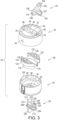
- FIG. 3 depicts the cap 22 in an exploded view, however, after the cap 22 is finally assembled, e.g., in a manufacturing facility, the cap 22 is not intended to be disassembled in the manner shown in FIG. 3 .
- the top cap 32 includes an upper wall 42 that is circular in plan view in the illustrated embodiment.
- An outer side wall 44 which is cylindrical in the illustrated embodiment, depends downwardly from a periphery of the upper wall 42.
- the top cap 32 further includes a spout receiving recess 46 that is rectangular in plan view in the illustrated embodiment.
- the spout receiving recess 46 is defined by opposing recess side walls 48, 52 which depend vertically downward from the upper wall 42.
- the spout receiving recess 46 is also defined by a recess floor 54, which is planar and horizontally oriented in the illustrated embodiment.
- the spout receiving recess 46 also includes a distal end wall 56 and a proximal end wall 58 ( FIG. 5 ), both of which depend downwardly from the upper wall 42.
- the top cap 32 also includes a downwardly depending valve receiving wall 62 which defines the valve receiving passage 38.
- the spout 24 and the cap 22 include cooperating axle features to pivotally connect the spout 24 with the cap 22.
- the top cap 32 includes axles 68, 72 each extending inwardly from a respective opposing recess side wall 48, 52.
- the axles 68, 72 define a pivot axis 74 ( FIG. 5 ) about which the spout 24 pivots with respect to the cap 22.
- the top cap 32 further includes concave surfaces 78, 82 disposed on opposite sides of the valve receiving passage 38 when the cap 22 is assembled.
- the concave surfaces 78, 82 substantially follow a radius emanating from the pivot axis 74.
- the bottom cap 34 includes a lower wall 92 that is circular in plan view in the illustrated embodiment.
- the lower wall 92 includes a valve receiving opening 94 that defines a portion of the valve receiving passage 38.
- An inner wall 96 extends upwardly from the lower wall 92.
- the bottom cap 34 also includes an upper wall 98 extending radially outward from the inner wall 96.
- the bottom cap 34 also includes an outer wall 102, which is cylindrical in the illustrated embodiment, extending upwardly and downwardly from the upper wall 98.
- internal threads 104 are provided on the outer wall 102 beneath the upper wall 98 to facilitate connecting the cap 22 to the drinking vessel 28 ( FIG. 1 ).
- the outer wall 102 of the bottom cap 34 is received within the outer side wall 44 of the top cap 32 when the cap 22 is assembled.
- the insulation insert 36 includes a U-shaped lower body section 116.
- the U-shaped lower body section 116 includes a recess 118 corresponding with the valve receiving passage 38 when the cap 22 is finally assembled.
- the insulation insert 36 also includes opposing segments 122, 124 on opposite sides of the recess 118.
- Each opposing segment 122, 124 includes respective internal walls 126, 128 defining respective elongate voids 132, 134.
- the spout 24 includes a base 150 and an extension 152 extending from the base 150.
- An inner passage 154 extends through the base 150 and the extension 152. The inner passage 154 is in fluid communication with the drinking vessel 28 when the spout 24 is in the drinking position ( FIG. 1 ) and is closed off from the drinking vessel 28 when the spout 24 is in the closed position ( FIGS. 2 and 6 ).
- the base 150 is rounded in the illustrated embodiment.
- the base 150 includes a convex outer surface 156.
- the convex outer surface 156 follows the radius emanating from the pivot axis 74 about which the spout 24 pivots with respect to the cap 22.
- the extension 152 extends from the base 150.
- a flange 158 extends away from the extension 152 in a direction generally perpendicular to the longest dimension of the inner passage 154.
- a finger recess 162 is provided in the flange 158 to receive a finger or thumb to facilitate pivotal movement of the spout 24 with respect to the cap 22.
- a bump 164 also extends from the extension 152 in a direction generally opposite that to which the flange 158 extends from the extension 152. The bump 164 operates as a vent closure when the spout 24 is in the closed position (see FIG. 6 ).
- the spout 24 and the cap 22 include cooperating axle features to pivotally connect the spout 24 with the cap 22.
- the axle features include the axles 68, 72 and circular recesses 168, 172, which in the illustrated embodiment are provided in the base 150 of the spout 24.
- Each axle 68, 72 is received within a respective circular recess 168, 172, which allows the spout 24 to pivot with respect to the cap 22.
- the spout 24 further includes channels 174, 176. Each channel 174, 176 emanates from a respective circular recess 168, 172.
- Each channel 174, 176 has a width that is slightly larger than a diameter of the respective axle 68, 72 and approximately equal to a diameter of the circular recess 168, 172 from which it emanates.
- Each axle 68, 72 is receivable in a respective channel 174, 176 to allow for selective removal of the spout 24 from the cap 22 when pulled in a direction parallel with the length of each channel 174, 176.
- Each of the channels 174, 176 is oriented such that removal of the spout 24 from the cap 22 is precluded when the spout 24 is in the drinking position.
- a user can grasp the flange 158 and pull the spout 24 with respect to the cap 22 in a direction (arrow 180) aligned with the length (longest dimension) of each channel 174, 176.
- the axles 68, 72 are pulled from the circular recess 168, 172 and enter the channels 174, 176 until the spout 24 is removed from the cap 22.
- FIG. 8 when the spout 24 is in the closed position ( FIG. 8 ) a user can grasp the flange 158 and pull the spout 24 with respect to the cap 22 in a direction (arrow 180) aligned with the length (longest dimension) of each channel 174, 176.
- the axles 68, 72 are pulled from the circular recess 168, 172 and enter the channels 174, 176 until the sp
- each channel 174, 176 is oriented such that pulling the spout 24 with respect to the cap 22 in the direction (arrow 182) aligned with the length of each channel 174, 176 is precluded because the spout 24 is in contact with the cap 22, which precludes removal in that direction.
- the axles 68, 72 can be aligned with the channels 174, 176 and the spout 24 can be pushed toward the cap 22 in a direction aligned with the length of each channel 174, 176 until the axles 68, 72 are received in the circular recesses 168, 172.
- axles similar to the axles 68, 72 can be provided on the spout 24 and the circular recesses and channels can be provided on the cap 22.
- Both the cap 22 and the spout 24 can be made from relatively more rigid plastics as compared to the plastic from which the valve member 26 is made.
- the valve member 26 is made from a resilient material, such as silicone.
- the valve member 26 includes a main valve body 210 which is an integrally formed solid piece of silicone.
- the main valve body 210 fills the valve receiving passage 38 and seals against an inner side of the valve receiving passage 38.
- the valve receiving passage 38 extends through the cap 22 from the lower wall 92 to the recess floor 54 of the spout receiving recess 46. The allows for a large opening in the cap 22, which can be more easily cleaned, as compared to straw lid cap assemblies in which the straw connects with a more permanent feature on the cap.
- the valve member 26 includes an uppermost surface 212, which is planar in the illustrated embodiment.
- the valve member 26 also includes a lower surface 214, which is also planar in the illustrated embodiment.
- a vent passage 216 extends from a lower vent opening 218 provided in the lower surface 214 to an upper vent opening 222 provided in the uppermost surface 212. As shown in FIG. 6 , the upper vent opening 222 is closed by the bump 164 when the spout 24 is in the closed position.
- the vent passage 216 is open to ambient when the spout 24 is in the drinking position.
- a drink passage which includes a lower passage 224 and an upper passage 226 extends through the main valve body 210.
- the drink passage includes a shoulder 228 between the lower passage 224 and the upper passage 226, which has a diameter less than the lower passage 224.
- the lower passage 224 begins at a lower drink opening 232 provided in the lower surface 214.
- the drink passage also includes an upper drink opening 234 that is surrounded by a flexible sealing ring 236, which will be described in more detail below.
- the shoulder 228 is axially offset from the flexible sealing ring 236, which allows the flexible sealing ring 236 to flex toward the shoulder 228 to provide an adequate seal to prevent liquid from leaking from the straw lid valve assembly 20.
- the lower passage 224 is configured to receive a straw 240 within the lower passage 224. The straw 240 is inserted so as to contact the shoulder 228 and the flexible sealing ring 236 is offset axially above the top end of the straw 240 when the straw 240 is inserted, which allows for desirable movement of the flexible
- the valve member 26 is received in the valve receiving passage 38 of the cap 22 so as to be in an operative position (shown in FIGS. 1 , 6 and 9 ) in which the valve member 26 can cooperate with the spout 24 to provide for selective communication between the inner passage 154 of the spout 24 and the straw 240.
- the valve member 26 includes a concave bearing surface 246.
- the concave bearing surface 246 follows the radius emanating from the pivot axis 74 when the valve member 26 is received in the operative position in the cap 22.
- an outer convex surface 248 surrounds the upper drink opening 234. As seen in FIG.
- the flexible sealing ring 236 and the outer convex surface 248, which is no longer convex, are biased towards a concave configuration when in contact with the convex outer surface 156 of the spout 24 to provide adequate sealing. Additionally, the outer convex surface 248 of the flexible sealing ring 236 deforms toward a concave configuration when in contact with the convex outer surface 156 of the spout 24 and a lowermost edge 252 of the flexible sealing ring 236 is spaced from the shoulder 228 when the flexible sealing ring 236 is in the concave configuration.
- the flexible sealing ring 236 provides a self-adjusting seal that is under light pressure that is capable of conforming to the shape of the convex outer surface 156 of the spout, which allows for some misalignment of the convex outer surface 156 with respect to the concave bearing surface 246 of the valve member 26. As such, the likelihood of leaks in the straw lid valve assembly 20 is mitigated. While the figures depict the outer convex surface 248 surrounds the upper drink opening 234, the flexible sealing ring 236 may work as well where its outer surface follows the contour of the concave bearing surface 246. In this configuration, it is still desirable to have the lowermost edge 252 of the flexible sealing ring 236 spaced from the shoulder 228 when the flexible sealing ring 236 is in the concave configuration similar to that shown in FIG. 6 .
- the valve member 26 includes a downward flange 260 depending downwardly from the lower surface 214.
- a recess 262 is provided in the downward flange 260, which allows a user to grip the downward flange 260 when removing the valve member 26 from the cap 22.
- the valve member 26 further includes a lower outer flange 264 that defines an outer recess 266 that cooperates with the bottom cap 34 when the valve member 26 is received in the cap 22 in the operative position.
- the valve member 26 is receivable in and removable from the cap 22, which facilitates cleaning. Also, the spout 24 is removable from the cap 22, which also facilitates cleaning. Moreover, the valve member 26 includes the drink passage 224, 226 and the vent passage 216 both of which are in fluid communication with the drinking vessel 28 through the straw 240 when the cap 22 is connected with the drinking vessel 28 and the valve member 26 is received in an operative position in the cap 22. The valve member 26 is receivable in the valve receiving passage 38 such that the uppermost surface 212 of the valve member 26 is exposed to ambient when the spout 24 is in the drinking position and the valve member 26 is received in the operative position in the cap 22. In many traditional straw valve assemblies, the vent opening in provided in a more rigid cap.
Landscapes
- Engineering & Computer Science (AREA)
- Mechanical Engineering (AREA)
- Closures For Containers (AREA)
Description
- Drinking vessels that include straw lid caps often include a spout that pivots with respect to the cap. Traditionally, seals on these straw lids are typically an O-ring gasket that is compressed between a ball at one end of the spout and a cap to create a seal when the spout is in the closed position. These seals are prone to leaking when this compression is insufficient. Additionally, the O-ring can wear over time causing a leak.
-
US 3,568,895 discloses a dispensing closure cap having a pivoting spout cooperating with an insert; however, the dispensing closure cap lacks a vent and is not described as cooperating with a straw. The insert includes a main disc body formed with a semispherical socket formation in which an outlet hole is provided. The spout includes a spherical base portion from which extends an arm portion. An outlet passageway extends through the base portion and the arm portion. The outlet hole of the insert is sealed by a plug that is attached at its lower end inside a recess provided in the base of the spout.US 5,873,478 discloses a spill-proof cap or lid for a standard beverage container, such as a soft drink, water and other liquid bottle, includes a housing which is configured to fit over the container opening. The housing includes top and bottom, each of which includes a recess. A spout is mounted in the top recess and is pivotable between open and closed positions. A flow control section extends generally vertically in the bottom recess for receiving a flow control member. The flow control member is removably positioned in the flow control section and includes a flow control valve and an air intake valve. The spout includes at least one passageway which is in fluid communication with the bottom recess through a passageway extending between the top and bottom of the housing. - In view of the foregoing, a straw lid valve assembly in accordance with independent claim 1 is provided.
-
-
FIG. 1 is a perspective view of a straw lid cap assembly removed from a drinking vessel. -
FIG. 2 is another perspective view of the straw lid cap assembly with a spout in a closed position. -
FIG. 3 is an exploded view of the straw lid cap assembly shown inFIG. 1 . -
FIG. 4 is a disassembled view of the straw lid cap assembly shown inFIG. 1 . -
FIG. 5 is an exploded cross-sectional view of the straw lid cap assembly shown inFIG. 1 . -
FIG. 6 is a cross-sectional view of the straw lid cap assembly shown inFIG. 1 with the spout in the closed position. -
FIG. 7 is a cross-sectional view of the straw lid cap assembly shown inFIG. 1 with the spout in a drinking position showing cooperating axle features to pivotally connect the spout with a cap. -
FIG. 8 is a cross-sectional view of the straw lid cap assembly shown inFIG. 1 with the spout in the closed position showing cooperating axle features to pivotally connect the spout with the cap. -
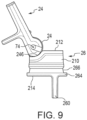
FIG. 9 is a side view of the spout and a valve member of the straw lid cap assembly with the valve member in an operative position and the spout in the drinking position. -
FIG. 1 depicts a strawlid valve assembly 20 including acap 22, aspout 24, and avalve member 26. Thecap 22 is configured to connect with adrinking vessel 28 to close an upper opening 30 of thedrinking vessel 28. Thespout 24 pivotally connects with thecap 22. Thespout 24 is pivotal between a drinking position shown inFIG. 1 and a closed position shown inFIG. 2 . Thevalve member 26 is received in thecap 22 so as to cooperate with thespout 24 to provide selective fluid communication between thedrinking vessel 28 and ambient through thespout 24 and thevalve member 26. - With reference to
FIG. 3 , in the illustrated embodiment, thecap 22 is an assembly including atop cap 32, abottom cap 34, and an insulation insert 36. When assembled, thetop cap 32 connects with thebottom cap 34 with theinsulation insert 36 disposed between thetop cap 32 and thebottom cap 34. When assembled, thecap 22 includes a valve receiving passage 38 (FIG. 4 ) configured to selectively receive thevalve member 26.FIG. 4 depicts the strawlid valve assembly 20 disassembled in a manner that can be accomplished by a person to clean the strawlid valve assembly 20.FIG. 3 depicts thecap 22 in an exploded view, however, after thecap 22 is finally assembled, e.g., in a manufacturing facility, thecap 22 is not intended to be disassembled in the manner shown inFIG. 3 . - With reference back to
FIG. 3 , thetop cap 32 includes anupper wall 42 that is circular in plan view in the illustrated embodiment. Anouter side wall 44, which is cylindrical in the illustrated embodiment, depends downwardly from a periphery of theupper wall 42. Thetop cap 32 further includes aspout receiving recess 46 that is rectangular in plan view in the illustrated embodiment. Thespout receiving recess 46 is defined by opposingrecess side walls 48, 52 which depend vertically downward from theupper wall 42. Thespout receiving recess 46 is also defined by arecess floor 54, which is planar and horizontally oriented in the illustrated embodiment. Thespout receiving recess 46 also includes adistal end wall 56 and a proximal end wall 58 (FIG. 5 ), both of which depend downwardly from theupper wall 42. Thetop cap 32 also includes a downwardly dependingvalve receiving wall 62 which defines thevalve receiving passage 38. - The
spout 24 and thecap 22 include cooperating axle features to pivotally connect thespout 24 with thecap 22. In the illustrated embodiment, thetop cap 32 includesaxles recess side wall 48, 52. Theaxles FIG. 5 ) about which the spout 24 pivots with respect to thecap 22. Thetop cap 32 further includesconcave surfaces valve receiving passage 38 when thecap 22 is assembled. Theconcave surfaces pivot axis 74. - The
bottom cap 34 includes alower wall 92 that is circular in plan view in the illustrated embodiment. Thelower wall 92 includes avalve receiving opening 94 that defines a portion of thevalve receiving passage 38. Aninner wall 96 extends upwardly from thelower wall 92. Thebottom cap 34 also includes anupper wall 98 extending radially outward from theinner wall 96. Thebottom cap 34 also includes anouter wall 102, which is cylindrical in the illustrated embodiment, extending upwardly and downwardly from theupper wall 98. With reference toFIG. 5 ,internal threads 104 are provided on theouter wall 102 beneath theupper wall 98 to facilitate connecting thecap 22 to the drinking vessel 28 (FIG. 1 ). Theouter wall 102 of thebottom cap 34 is received within theouter side wall 44 of thetop cap 32 when thecap 22 is assembled. - With reference back to
FIG. 3 , theinsulation insert 36 includes a U-shapedlower body section 116. The U-shapedlower body section 116 includes arecess 118 corresponding with thevalve receiving passage 38 when thecap 22 is finally assembled. Theinsulation insert 36 also includesopposing segments 122, 124 on opposite sides of therecess 118. Eachopposing segment 122, 124 includes respectiveinternal walls elongate voids - The
spout 24 includes abase 150 and anextension 152 extending from thebase 150. Aninner passage 154 extends through thebase 150 and theextension 152. Theinner passage 154 is in fluid communication with thedrinking vessel 28 when thespout 24 is in the drinking position (FIG. 1 ) and is closed off from thedrinking vessel 28 when thespout 24 is in the closed position (FIGS. 2 and6 ). - The
base 150 is rounded in the illustrated embodiment. Thebase 150 includes a convexouter surface 156. When thespout 24 is connected with thecap 22, the convexouter surface 156 follows the radius emanating from thepivot axis 74 about which thespout 24 pivots with respect to thecap 22. - The
extension 152 extends from thebase 150. Aflange 158 extends away from theextension 152 in a direction generally perpendicular to the longest dimension of theinner passage 154. Afinger recess 162 is provided in theflange 158 to receive a finger or thumb to facilitate pivotal movement of thespout 24 with respect to thecap 22. Abump 164 also extends from theextension 152 in a direction generally opposite that to which theflange 158 extends from theextension 152. Thebump 164 operates as a vent closure when thespout 24 is in the closed position (seeFIG. 6 ). - As mentioned above, the
spout 24 and thecap 22 include cooperating axle features to pivotally connect thespout 24 with thecap 22. The axle features include theaxles circular recesses base 150 of thespout 24. Eachaxle circular recess spout 24 to pivot with respect to thecap 22. In the illustrated embodiment, thespout 24 further includeschannels channel circular recess channel respective axle circular recess axle respective channel spout 24 from thecap 22 when pulled in a direction parallel with the length of eachchannel - Each of the
channels spout 24 from thecap 22 is precluded when thespout 24 is in the drinking position. As seen when comparingFIG. 7 to FIG. 8 , when thespout 24 is in the closed position (FIG. 8 ) a user can grasp theflange 158 and pull thespout 24 with respect to thecap 22 in a direction (arrow 180) aligned with the length (longest dimension) of eachchannel axles circular recess channels spout 24 is removed from thecap 22. In contrast, as seen inFIG. 7 with thespout 24 in the drinking position, eachchannel spout 24 with respect to thecap 22 in the direction (arrow 182) aligned with the length of eachchannel spout 24 is in contact with thecap 22, which precludes removal in that direction. With thespout 24 removed from thecap 22, theaxles channels spout 24 can be pushed toward thecap 22 in a direction aligned with the length of eachchannel axles circular recesses - The axle features shown in the illustrated embodiment can be reversed in that axles similar to the
axles spout 24 and the circular recesses and channels can be provided on thecap 22. - Both the
cap 22 and thespout 24 can be made from relatively more rigid plastics as compared to the plastic from which thevalve member 26 is made. In the illustrated embodiment, thevalve member 26 is made from a resilient material, such as silicone. Thevalve member 26 includes amain valve body 210 which is an integrally formed solid piece of silicone. Themain valve body 210 fills thevalve receiving passage 38 and seals against an inner side of thevalve receiving passage 38. Thevalve receiving passage 38 extends through thecap 22 from thelower wall 92 to therecess floor 54 of thespout receiving recess 46. The allows for a large opening in thecap 22, which can be more easily cleaned, as compared to straw lid cap assemblies in which the straw connects with a more permanent feature on the cap. - The
valve member 26 includes anuppermost surface 212, which is planar in the illustrated embodiment. Thevalve member 26 also includes alower surface 214, which is also planar in the illustrated embodiment. Avent passage 216 extends from alower vent opening 218 provided in thelower surface 214 to an upper vent opening 222 provided in theuppermost surface 212. As shown inFIG. 6 , the upper vent opening 222 is closed by thebump 164 when thespout 24 is in the closed position. Thevent passage 216 is open to ambient when thespout 24 is in the drinking position. - A drink passage, which includes a
lower passage 224 and anupper passage 226 extends through themain valve body 210. The drink passage includes ashoulder 228 between thelower passage 224 and theupper passage 226, which has a diameter less than thelower passage 224. Thelower passage 224 begins at alower drink opening 232 provided in thelower surface 214. The drink passage also includes anupper drink opening 234 that is surrounded by aflexible sealing ring 236, which will be described in more detail below. Theshoulder 228 is axially offset from theflexible sealing ring 236, which allows theflexible sealing ring 236 to flex toward theshoulder 228 to provide an adequate seal to prevent liquid from leaking from the strawlid valve assembly 20. Thelower passage 224 is configured to receive astraw 240 within thelower passage 224. Thestraw 240 is inserted so as to contact theshoulder 228 and theflexible sealing ring 236 is offset axially above the top end of thestraw 240 when thestraw 240 is inserted, which allows for desirable movement of theflexible sealing ring 236. - The
valve member 26 is received in thevalve receiving passage 38 of thecap 22 so as to be in an operative position (shown inFIGS. 1 ,6 and9 ) in which thevalve member 26 can cooperate with thespout 24 to provide for selective communication between theinner passage 154 of thespout 24 and thestraw 240. Thevalve member 26 includes aconcave bearing surface 246. In the illustrated embodiment, theconcave bearing surface 246 follows the radius emanating from thepivot axis 74 when thevalve member 26 is received in the operative position in thecap 22. In the illustrated embodiment, when theflexible sealing ring 236 is not in contact with theconcave bearing surface 246, an outerconvex surface 248 surrounds theupper drink opening 234. As seen inFIG. 6 , theflexible sealing ring 236 and the outerconvex surface 248, which is no longer convex, are biased towards a concave configuration when in contact with the convexouter surface 156 of thespout 24 to provide adequate sealing. Additionally, the outerconvex surface 248 of theflexible sealing ring 236 deforms toward a concave configuration when in contact with the convexouter surface 156 of thespout 24 and alowermost edge 252 of theflexible sealing ring 236 is spaced from theshoulder 228 when theflexible sealing ring 236 is in the concave configuration. As such, theflexible sealing ring 236 provides a self-adjusting seal that is under light pressure that is capable of conforming to the shape of the convexouter surface 156 of the spout, which allows for some misalignment of the convexouter surface 156 with respect to theconcave bearing surface 246 of thevalve member 26. As such, the likelihood of leaks in the strawlid valve assembly 20 is mitigated. While the figures depict the outerconvex surface 248 surrounds theupper drink opening 234, theflexible sealing ring 236 may work as well where its outer surface follows the contour of theconcave bearing surface 246. In this configuration, it is still desirable to have thelowermost edge 252 of theflexible sealing ring 236 spaced from theshoulder 228 when theflexible sealing ring 236 is in the concave configuration similar to that shown inFIG. 6 . - The
valve member 26 includes adownward flange 260 depending downwardly from thelower surface 214. A recess 262 is provided in thedownward flange 260, which allows a user to grip thedownward flange 260 when removing thevalve member 26 from thecap 22. Thevalve member 26 further includes a lowerouter flange 264 that defines anouter recess 266 that cooperates with thebottom cap 34 when thevalve member 26 is received in thecap 22 in the operative position. - The
valve member 26 is receivable in and removable from thecap 22, which facilitates cleaning. Also, thespout 24 is removable from thecap 22, which also facilitates cleaning. Moreover, thevalve member 26 includes thedrink passage vent passage 216 both of which are in fluid communication with thedrinking vessel 28 through thestraw 240 when thecap 22 is connected with thedrinking vessel 28 and thevalve member 26 is received in an operative position in thecap 22. Thevalve member 26 is receivable in thevalve receiving passage 38 such that theuppermost surface 212 of thevalve member 26 is exposed to ambient when thespout 24 is in the drinking position and thevalve member 26 is received in the operative position in thecap 22. In many traditional straw valve assemblies, the vent opening in provided in a more rigid cap. - A straw lid valve assembly has been described above in particularity. Modifications and alterations will occur to those upon reading and understanding the preceding detailed description. The invention, however, is not limited to only the embodiments described above. Instead, the invention is defined by the appended claims.
Claims (13)
- A straw lid valve assembly (20) comprising:a cap (22) configured to connect with a drinking vessel (28), the cap including a valve receiving passage (38);a spout (24) pivotally connected with the cap (22) and pivotal about a pivot axis (74) between a drinking position and a closed position, the spout (24) including an inner passage (154) that is in fluid communication with the drinking vessel (28) when in the drinking position and is closed off from the drinking vessel when in the closed position; anda valve member (26) received in the cap (22), and the valve member including a drink passage (224, 226) and a vent passage (216) both of which are in fluid communication with the drinking vessel (28) when the cap is connected with the drinking vessel and the valve member (26) is received in an operative position in the cap, wherein the valve member is received in the valve receiving passage (38) such that an uppermost surface (212) of the valve member is exposed to ambient when the spout (24) is in the drinking position and the valve member is received in the operative position in the cap, wherein the valve member (26) includes an upper vent opening (222) for the vent passage (216), characterized in that the spout (24) includes a vent closure (164) that closes the vent opening (222) when the spout is in the closed position
- The straw lid valve assembly of claim 1, wherein the valve member (26) is an integrally formed piece of resilient material that fills the valve receiving passage (38) and seals against an inner side of the valve receiving passage when the valve member is received in the operative position in the cap.
- The straw lid valve assembly of claim 1, wherein the drink passage (224, 226) includes a shoulder (228) between a lower passage (224) and an upper passage (226), which has a smaller diameter than the lower passage, wherein the lower passage is configured to receive an associated straw (240) within the lower passage.
- The straw lid valve assembly of claim 3, wherein the valve member (26) includes a flexible sealing ring (236) surrounding an upper drink opening (234) of the drink passage (224, 226), wherein the flexible sealing ring deforms toward a concave configuration when the spout (24) is in the drinking position and a lowermost edge (252) of the sealing ring is spaced from the shoulder (228) when the flexible sealing ring is in the concave configuration.
- The straw lid valve assembly of claim 1, wherein the valve member (26) includes a flexible sealing ring (236) surrounding an upper drink opening (234) of the drink passage (224, 226), wherein the flexible sealing ring is a self-adjusting seal capable of conforming to a convex outer surface (156) of the spout (24).
- The straw lid valve assembly of claim 5, wherein the flexible sealing ring (236) includes an outer convex surface (248) when not in contact with the convex outer surface (156) of the spout (24), and the outer convex surface of the flexible sealing ring deforms toward a concave configuration when in contact with the convex outer surface of the spout.
- The straw lid valve assembly of claim 1, wherein the spout (24) includes a convex outer surface (156) offset from the uppermost surface (212) and the valve member (26) includes a concave bearing surface (246) against which the convex outer surface bears when the valve member is received in the operative position in the cap (22).
- The straw lid valve assembly of claim 7, wherein the upper vent opening (222) of the vent passage (216) disposed within the uppermost surface (212) and an upper drink opening (234) of the drink passage is disposed within the concave bearing surface (246).
- The straw lid valve assembly of claim 1, wherein the vent closure is a bump (164) extending from the spout (24).
- The straw lid valve assembly of claim 1, wherein the spout (24) and the cap (22) include cooperating axle features to pivotally connect the spout with the cap, the axle features including an axle (68, 72) and a circular recess (168, 172) that receives the axle, and one of the spout and the cap includes a channel (174, 176) emanating from the circular recess, wherein the axle is receivable in the channel to allow for selective removal of the spout from the cap.
- The straw lid valve assembly of claim 10, wherein when the spout (24) is in the drinking position the channel (174, 176) being oriented such that removal of the spout from the cap (22) is precluded when pulling the spout away from the cap in a direction aligned with the length of the channel.
- The straw lid valve assembly of claim 11, wherein when the spout (24) is in the closed position the channel (174, 176) being oriented such pulling the spout away from the cap (22) in a direction aligned with the length of the channel results in removal of the spout from the cap.
- The straw lid valve assembly of claim 10, wherein the spout (24) is provided with the circular recess (168, 172) and the channel (174, 176), and the cap (22) is provided with the axle (68, 72).
Applications Claiming Priority (2)
| Application Number | Priority Date | Filing Date | Title |
|---|---|---|---|
| US16/565,569 US11358760B2 (en) | 2019-09-10 | 2019-09-10 | Straw lid assembly |
| PCT/US2020/049313 WO2021050367A1 (en) | 2019-09-10 | 2020-09-04 | Straw lid assembly |
Publications (3)
| Publication Number | Publication Date |
|---|---|
| EP4028334A1 EP4028334A1 (en) | 2022-07-20 |
| EP4028334A4 EP4028334A4 (en) | 2023-10-11 |
| EP4028334B1 true EP4028334B1 (en) | 2024-10-30 |
Family
ID=74850348
Family Applications (1)
| Application Number | Title | Priority Date | Filing Date |
|---|---|---|---|
| EP20862671.3A Active EP4028334B1 (en) | 2019-09-10 | 2020-09-04 | Straw lid assembly |
Country Status (5)
| Country | Link |
|---|---|
| US (1) | US11358760B2 (en) |
| EP (1) | EP4028334B1 (en) |
| JP (1) | JP7733860B2 (en) |
| CN (1) | CN114174187B (en) |
| WO (1) | WO2021050367A1 (en) |
Families Citing this family (22)
| Publication number | Priority date | Publication date | Assignee | Title |
|---|---|---|---|---|
| USD940501S1 (en) * | 2020-05-15 | 2022-01-11 | Helen Of Troy Limited | Straw cap |
| USD937038S1 (en) * | 2020-06-08 | 2021-11-30 | JDS Industries, Inc. | Cap for a beverage container |
| USD957196S1 (en) | 2020-10-27 | 2022-07-12 | Yeti Coolers, Llc | Bottle |
| USD990230S1 (en) * | 2021-06-02 | 2023-06-27 | Helen Of Troy Limited | Bottle straw lid |
| USD1036936S1 (en) | 2021-10-26 | 2024-07-30 | Yeti Coolers, Llc | Bottle |
| USD1032286S1 (en) * | 2022-03-01 | 2024-06-25 | Joe Brands, LLC | Bottle lid |
| USD1140644S1 (en) | 2022-10-26 | 2026-08-11 | Yeti Coolers, Llc | Bottle |
| USD1126670S1 (en) | 2022-10-26 | 2026-05-19 | Yeti Coolers, Llc | Bottle |
| USD1050801S1 (en) | 2022-12-16 | 2024-11-12 | Yeti Coolers, Llc | Lid |
| USD1050803S1 (en) | 2022-12-16 | 2024-11-12 | Yeti Coolers, Llc | Lid |
| USD1075418S1 (en) * | 2023-07-10 | 2025-05-20 | Hydrojug, Inc. | Container |
| USD1044392S1 (en) * | 2023-07-10 | 2024-10-01 | Hydrojug, Inc. | Container lid |
| USD1074299S1 (en) * | 2023-07-10 | 2025-05-13 | Hydrojug, Inc. | Container lid |
| BE1032203B1 (en) * | 2023-12-06 | 2025-07-07 | Mellis Bv | REUSABLE DRINKING BOTTLE WITH FLIP-OUT SPOUT |
| USD1054781S1 (en) * | 2024-04-16 | 2024-12-24 | Hydrojug, Inc. | Detachable flip-straw lid |
| USD1121390S1 (en) | 2024-07-19 | 2026-04-07 | Sharkninja Operating Llc | Beverage container |
| USD1058299S1 (en) * | 2024-08-13 | 2025-01-21 | Mali Lou | Travel mug |
| USD1067714S1 (en) * | 2024-08-17 | 2025-03-25 | Chenchen Qin | Cup lid |
| USD1140635S1 (en) | 2024-12-26 | 2026-08-11 | Yeti Coolers, Llc | Lid with straw |
| USD1126645S1 (en) | 2024-12-26 | 2026-05-19 | Yeti Coolers, Llc | Straw |
| US20260198717A1 (en) * | 2025-01-14 | 2026-07-16 | Base Brands, Llc | Drinking container with sanitary straw |
| US12612223B1 (en) | 2025-07-15 | 2026-04-28 | BruMate, LLC | Lid system for beverage container |
Family Cites Families (70)
| Publication number | Priority date | Publication date | Assignee | Title |
|---|---|---|---|---|
| US1747550A (en) * | 1927-08-17 | 1930-02-18 | Klimburg Rudolf | Closing device |
| US2032776A (en) | 1934-02-08 | 1936-03-03 | Henry E Van Ness | Dispensing container and closure therefor |
| US2134119A (en) | 1934-05-02 | 1938-10-25 | Svenska Kapsylfabriken Ab | Method of making closing means, especially for collapsible tubes |
| US2030696A (en) | 1935-02-25 | 1936-02-11 | Raymond Schmidt | Dispensing container |
| US2717726A (en) * | 1951-09-22 | 1955-09-13 | Harry A Mart | Combined spout and cock |
| US2800259A (en) | 1955-12-27 | 1957-07-23 | Poleete Inc | Container structures |
| US2883091A (en) | 1957-05-24 | 1959-04-21 | Domenick P Barravecchia | Combined cap, valve and dispensing spout for liquid containers |
| US2936934A (en) * | 1958-07-07 | 1960-05-17 | Ignas B Kubiliunas | Dispensing closures |
| US2971664A (en) * | 1959-02-17 | 1961-02-14 | Aladdin Ind Inc | Draw-through stopper for vacuum bottles or the like |
| US3023939A (en) * | 1959-03-16 | 1962-03-06 | Clifford R Jennings | Dispensing closures |
| US2979238A (en) * | 1959-04-15 | 1961-04-11 | Aladdin Ind Inc | Sip-through and pour-through closure for vacuum bottles or the like |
| US3036600A (en) | 1959-05-11 | 1962-05-29 | Fisher Governor Co | Sealed ball valve |
| US3089626A (en) * | 1960-05-25 | 1963-05-14 | Polytop Corp | Pouring spout construction |
| US3163337A (en) | 1962-11-02 | 1964-12-29 | Polytop Corp | Closure |
| US3265256A (en) | 1964-09-16 | 1966-08-09 | Ronson Corp | Spout structure |
| US3283967A (en) * | 1965-01-11 | 1966-11-08 | Polytop Corp | Dispensing closure |
| US3490659A (en) | 1966-08-15 | 1970-01-20 | Polytop Corp | Dispensing closures |
| US3502248A (en) * | 1967-06-09 | 1970-03-24 | Sidney M Libit | Fluid dispensing closure with a swivel spout |
| US3568895A (en) | 1968-07-30 | 1971-03-09 | Product Design & Engineering I | Dispensing closure cap for a container |
| US3653546A (en) * | 1970-03-23 | 1972-04-04 | Polytope Corp | Dispensing closure with rupturable diaphragm seal |
| US3751787A (en) | 1972-02-01 | 1973-08-14 | Product Design & Eng Inc | Method of mounting a sealing disc in a cap for a container |
| US3961770A (en) | 1973-09-04 | 1976-06-08 | Celanese Corporation | Plug valve |
| JPS5642191Y2 (en) * | 1975-06-10 | 1981-10-02 | ||
| US4209115A (en) | 1978-09-06 | 1980-06-24 | Georg Menshen & Co. Kg | Two-part delivery outlet closure for containers |
| US4219138A (en) | 1978-10-16 | 1980-08-26 | Polytop Corporation | Dispensing closure utilizing a sealing element supported by a washer spring |
| US4519529A (en) | 1979-10-22 | 1985-05-28 | King-Seeley Thermos Co. | Dispensing stopper |
| JPS59182223U (en) * | 1983-05-23 | 1984-12-05 | タケヤ化学工業株式会社 | Water bottle |
| US4595123A (en) * | 1983-06-17 | 1986-06-17 | Owens-Illinois, Inc. | Tamper evident closure cap |
| JPS60195752U (en) * | 1984-06-08 | 1985-12-27 | サンスタ−株式会社 | toggle cap |
| US4903870A (en) | 1988-10-19 | 1990-02-27 | Polytop Corporation | Dispensing closure |
| US5065909A (en) * | 1989-11-29 | 1991-11-19 | Threeco | Vented beverage can cover having pivotal spout |
| US5242079A (en) * | 1992-09-11 | 1993-09-07 | Three Co. | Sealable cover for an open beverage container |
| US5477994A (en) * | 1994-06-20 | 1995-12-26 | Rubbermaid Incorporated | Beverage container valve |
| GB2293818B (en) | 1994-10-07 | 1998-05-27 | Rpc Containers Ltd | Child-resistant dispensing device |
| US5524799A (en) * | 1994-11-10 | 1996-06-11 | Polytop Corporation | Dispensing closure employing standards with bearings to receive spout therein |
| BR9404733A (en) * | 1994-11-24 | 1995-08-01 | Sobral Invicta Sa | Improvement in lid, with serving device, for thermal containers |
| US5904337A (en) | 1996-07-31 | 1999-05-18 | Prolon Inc. | Ball valve seat and seal apparatus and assembly method |
| US5873478A (en) * | 1997-01-13 | 1999-02-23 | Sullivan; Michael J. | Spill-proof cap for beverage containers |
| US6032813A (en) | 1997-09-12 | 2000-03-07 | Becton, Dickinson And Company | Ball and socket closure for specimen collection container incorporating an integral flexible seal |
| AU689754B3 (en) * | 1997-12-02 | 1998-04-02 | Wang Wen-Pin | Cap assembly having a sucking member for a bottle |
| DE10151676A1 (en) * | 2001-10-19 | 2003-05-08 | Siemens & Co Quellenprodukte | nasal douche |
| US6793104B2 (en) * | 2001-12-17 | 2004-09-21 | I-Feng Kao | Cork device for resealing a bottle |
| US20050150916A1 (en) * | 2003-12-18 | 2005-07-14 | L'oreal | Dispenser device having a pivotable nozzle |
| IL166540A0 (en) * | 2005-01-27 | 2006-01-15 | Amnon Shiloni | Bottle cap |
| US7533783B2 (en) * | 2005-04-11 | 2009-05-19 | Camelbak Products, Llc | Drink bottles with bite-actuated mouthpieces |
| US9149808B1 (en) | 2007-08-30 | 2015-10-06 | Jeffrey P. Smith | Ball and socket valve for a fluid container |
| US20090120946A1 (en) * | 2007-11-12 | 2009-05-14 | Ming-Hua Hung | Cap With Suction Unit For Cup |
| WO2009123661A1 (en) | 2008-03-31 | 2009-10-08 | Nike, Inc. | Container for dispensing a fluid |
| US7988013B2 (en) | 2009-03-25 | 2011-08-02 | Jih-Liang Lin | Flow control device |
| CN201754914U (en) * | 2010-07-08 | 2011-03-09 | 察可汗设计公司 | Water bottle cover for drinking water |
| US8459502B2 (en) * | 2010-09-03 | 2013-06-11 | Calibre Closures, LLC | Reclosable dispensing closure with vent |
| US20120181277A1 (en) * | 2011-01-13 | 2012-07-19 | Ching Yueh Wang-Wu | Lid of a canteen |
| US20120305559A1 (en) * | 2011-05-31 | 2012-12-06 | Zak Designs, Inc. | Fluid dispensing vessel |
| US9061813B2 (en) | 2012-06-28 | 2015-06-23 | Zak Designs, Inc. | Liquid metering assembly |
| US8668106B1 (en) * | 2012-11-20 | 2014-03-11 | Lifefactory, Inc. | Fluid container cover |
| US20140353275A1 (en) * | 2013-05-30 | 2014-12-04 | Headwind Ceramic Ltd. | Valved cap for beverage containers |
| CA2930610A1 (en) | 2013-12-19 | 2015-06-25 | Angelcare Feeding Usa, Llc | Lid for a container |
| US20150257558A1 (en) * | 2014-03-11 | 2015-09-17 | Remark-A-Ball Llc | Spherical drinking vessel |
| US9879789B2 (en) | 2014-12-09 | 2018-01-30 | Cameron International Corporation | Ball valve seal |
| US9650189B1 (en) | 2015-10-29 | 2017-05-16 | Tervis Tumbler Company | Drinking vessels including devices for providing a mixed liquid therefrom |
| US9573738B1 (en) * | 2015-12-23 | 2017-02-21 | Sara Rose International Inc. | Beverage container cap |
| US10214330B2 (en) | 2015-12-30 | 2019-02-26 | Thermos Llc | Fluid container with axis straw |
| US10433665B2 (en) * | 2016-01-25 | 2019-10-08 | Handi-Craft Company | Valve assembly for leak resistant straw cup |
| USD812966S1 (en) * | 2016-08-19 | 2018-03-20 | O2C Raleigh, Llc | Cap for a container |
| US10159368B2 (en) * | 2017-05-17 | 2018-12-25 | Shin-Shuoh Lin | Multifunctional mug cap with a sipper and straw |
| US20190263572A1 (en) * | 2018-02-28 | 2019-08-29 | O2Cool, Llc | Bottle Closure |
| US10858158B2 (en) * | 2018-09-25 | 2020-12-08 | Zhejiang Haoda Science & Technology Co., Ltd | Container with an elastic spout |
| US11097875B2 (en) * | 2019-07-02 | 2021-08-24 | Alan Lee Starner | Dual ball valve straw lid for closed container |
| US11214399B1 (en) * | 2019-07-24 | 2022-01-04 | HopOver Ventures LLC | Multi-compartment bottle |
| US11535433B2 (en) * | 2019-11-15 | 2022-12-27 | Helen Of Troy Limited | Container closure with venting seal |
-
2019
- 2019-09-10 US US16/565,569 patent/US11358760B2/en active Active
-
2020
- 2020-09-04 EP EP20862671.3A patent/EP4028334B1/en active Active
- 2020-09-04 CN CN202080052623.7A patent/CN114174187B/en active Active
- 2020-09-04 JP JP2022514545A patent/JP7733860B2/en active Active
- 2020-09-04 WO PCT/US2020/049313 patent/WO2021050367A1/en not_active Ceased
Also Published As
| Publication number | Publication date |
|---|---|
| CN114174187A (en) | 2022-03-11 |
| EP4028334A1 (en) | 2022-07-20 |
| US11358760B2 (en) | 2022-06-14 |
| CN114174187B (en) | 2023-05-02 |
| EP4028334A4 (en) | 2023-10-11 |
| US20210070508A1 (en) | 2021-03-11 |
| WO2021050367A1 (en) | 2021-03-18 |
| JP2022547867A (en) | 2022-11-16 |
| JP7733860B2 (en) | 2025-09-04 |
Similar Documents
| Publication | Publication Date | Title |
|---|---|---|
| US11358760B2 (en) | Straw lid assembly | |
| JP5041560B2 (en) | Lid for beverage containers to prevent liquid leakage | |
| AU2005244643B2 (en) | Feeding bottle | |
| US8403168B2 (en) | Cup assembly | |
| US6732882B2 (en) | No-spill cover assemly for a drink container | |
| CN105848540B (en) | cover with check valve | |
| CA2319503C (en) | Leak-proof cup with flow control | |
| US5890628A (en) | Dispensing lid assembly for a container | |
| US6050433A (en) | Container closure | |
| EP2181933A2 (en) | Drinking vessel having a vacuum venting valve | |
| KR20130082064A (en) | Beverage container | |
| US20050205587A1 (en) | Cup assembly | |
| IL278446B2 (en) | Drinking vessel and ventilation members | |
| US20140246463A1 (en) | Beverage dispensing flow control device and method thereof | |
| US20240199291A1 (en) | Beverage container and cover unit | |
| CN106458390B (en) | Cap assembly for drinking container | |
| JP2024112772A (en) | Lid assembly with slider for beverage container - Patents.com | |
| US9901199B2 (en) | Liquid dispensing lid | |
| US20050167437A1 (en) | Drinking aid | |
| KR100613226B1 (en) | Cap of soda container | |
| CN106455838B (en) | Lid arrangement for drinking container | |
| JP4974063B2 (en) | Storage container | |
| KR102890143B1 (en) | cap unit and cap-equipped container | |
| JPH0334100Y2 (en) | ||
| JPH0213317Y2 (en) |
Legal Events
| Date | Code | Title | Description |
|---|---|---|---|
| STAA | Information on the status of an ep patent application or granted ep patent |
Free format text: STATUS: THE INTERNATIONAL PUBLICATION HAS BEEN MADE |
|
| PUAI | Public reference made under article 153(3) epc to a published international application that has entered the european phase |
Free format text: ORIGINAL CODE: 0009012 |
|
| STAA | Information on the status of an ep patent application or granted ep patent |
Free format text: STATUS: REQUEST FOR EXAMINATION WAS MADE |
|
| 17P | Request for examination filed |
Effective date: 20220328 |
|
| AK | Designated contracting states |
Kind code of ref document: A1 Designated state(s): AL AT BE BG CH CY CZ DE DK EE ES FI FR GB GR HR HU IE IS IT LI LT LU LV MC MK MT NL NO PL PT RO RS SE SI SK SM TR |
|
| DAV | Request for validation of the european patent (deleted) | ||
| DAX | Request for extension of the european patent (deleted) | ||
| P01 | Opt-out of the competence of the unified patent court (upc) registered |
Effective date: 20230614 |
|
| A4 | Supplementary search report drawn up and despatched |
Effective date: 20230912 |
|
| RIC1 | Information provided on ipc code assigned before grant |
Ipc: A47G 19/22 20060101ALI20230906BHEP Ipc: B65D 47/06 20060101ALI20230906BHEP Ipc: B65D 47/30 20060101AFI20230906BHEP |
|
| GRAP | Despatch of communication of intention to grant a patent |
Free format text: ORIGINAL CODE: EPIDOSNIGR1 |
|
| STAA | Information on the status of an ep patent application or granted ep patent |
Free format text: STATUS: GRANT OF PATENT IS INTENDED |
|
| INTG | Intention to grant announced |
Effective date: 20240418 |
|
| GRAS | Grant fee paid |
Free format text: ORIGINAL CODE: EPIDOSNIGR3 |
|
| GRAA | (expected) grant |
Free format text: ORIGINAL CODE: 0009210 |
|
| STAA | Information on the status of an ep patent application or granted ep patent |
Free format text: STATUS: THE PATENT HAS BEEN GRANTED |
|
| AK | Designated contracting states |
Kind code of ref document: B1 Designated state(s): AL AT BE BG CH CY CZ DE DK EE ES FI FR GB GR HR HU IE IS IT LI LT LU LV MC MK MT NL NO PL PT RO RS SE SI SK SM TR |
|
| REG | Reference to a national code |
Ref country code: GB Ref legal event code: FG4D |
|
| REG | Reference to a national code |
Ref country code: CH Ref legal event code: EP |
|
| REG | Reference to a national code |
Ref country code: DE Ref legal event code: R096 Ref document number: 602020040512 Country of ref document: DE |
|
| REG | Reference to a national code |
Ref country code: IE Ref legal event code: FG4D |
|
| REG | Reference to a national code |
Ref country code: LT Ref legal event code: MG9D |
|
| REG | Reference to a national code |
Ref country code: NL Ref legal event code: MP Effective date: 20241030 |
|
| PG25 | Lapsed in a contracting state [announced via postgrant information from national office to epo] |
Ref country code: IS Free format text: LAPSE BECAUSE OF FAILURE TO SUBMIT A TRANSLATION OF THE DESCRIPTION OR TO PAY THE FEE WITHIN THE PRESCRIBED TIME-LIMIT Effective date: 20250228 Ref country code: PT Free format text: LAPSE BECAUSE OF FAILURE TO SUBMIT A TRANSLATION OF THE DESCRIPTION OR TO PAY THE FEE WITHIN THE PRESCRIBED TIME-LIMIT Effective date: 20250228 Ref country code: HR Free format text: LAPSE BECAUSE OF FAILURE TO SUBMIT A TRANSLATION OF THE DESCRIPTION OR TO PAY THE FEE WITHIN THE PRESCRIBED TIME-LIMIT Effective date: 20241030 |
|
| PG25 | Lapsed in a contracting state [announced via postgrant information from national office to epo] |
Ref country code: FI Free format text: LAPSE BECAUSE OF FAILURE TO SUBMIT A TRANSLATION OF THE DESCRIPTION OR TO PAY THE FEE WITHIN THE PRESCRIBED TIME-LIMIT Effective date: 20241030 Ref country code: NL Free format text: LAPSE BECAUSE OF FAILURE TO SUBMIT A TRANSLATION OF THE DESCRIPTION OR TO PAY THE FEE WITHIN THE PRESCRIBED TIME-LIMIT Effective date: 20241030 |
|
| REG | Reference to a national code |
Ref country code: AT Ref legal event code: MK05 Ref document number: 1736695 Country of ref document: AT Kind code of ref document: T Effective date: 20241030 |
|
| PG25 | Lapsed in a contracting state [announced via postgrant information from national office to epo] |
Ref country code: BG Free format text: LAPSE BECAUSE OF FAILURE TO SUBMIT A TRANSLATION OF THE DESCRIPTION OR TO PAY THE FEE WITHIN THE PRESCRIBED TIME-LIMIT Effective date: 20241030 |
|
| PG25 | Lapsed in a contracting state [announced via postgrant information from national office to epo] |
Ref country code: ES Free format text: LAPSE BECAUSE OF FAILURE TO SUBMIT A TRANSLATION OF THE DESCRIPTION OR TO PAY THE FEE WITHIN THE PRESCRIBED TIME-LIMIT Effective date: 20241030 |
|
| PG25 | Lapsed in a contracting state [announced via postgrant information from national office to epo] |
Ref country code: NO Free format text: LAPSE BECAUSE OF FAILURE TO SUBMIT A TRANSLATION OF THE DESCRIPTION OR TO PAY THE FEE WITHIN THE PRESCRIBED TIME-LIMIT Effective date: 20250130 |
|
| PG25 | Lapsed in a contracting state [announced via postgrant information from national office to epo] |
Ref country code: GR Free format text: LAPSE BECAUSE OF FAILURE TO SUBMIT A TRANSLATION OF THE DESCRIPTION OR TO PAY THE FEE WITHIN THE PRESCRIBED TIME-LIMIT Effective date: 20250131 Ref country code: LV Free format text: LAPSE BECAUSE OF FAILURE TO SUBMIT A TRANSLATION OF THE DESCRIPTION OR TO PAY THE FEE WITHIN THE PRESCRIBED TIME-LIMIT Effective date: 20241030 Ref country code: AT Free format text: LAPSE BECAUSE OF FAILURE TO SUBMIT A TRANSLATION OF THE DESCRIPTION OR TO PAY THE FEE WITHIN THE PRESCRIBED TIME-LIMIT Effective date: 20241030 |
|
| PG25 | Lapsed in a contracting state [announced via postgrant information from national office to epo] |
Ref country code: PL Free format text: LAPSE BECAUSE OF FAILURE TO SUBMIT A TRANSLATION OF THE DESCRIPTION OR TO PAY THE FEE WITHIN THE PRESCRIBED TIME-LIMIT Effective date: 20241030 |
|
| PG25 | Lapsed in a contracting state [announced via postgrant information from national office to epo] |
Ref country code: RS Free format text: LAPSE BECAUSE OF FAILURE TO SUBMIT A TRANSLATION OF THE DESCRIPTION OR TO PAY THE FEE WITHIN THE PRESCRIBED TIME-LIMIT Effective date: 20250130 |
|
| REG | Reference to a national code |
Ref country code: DE Ref legal event code: R081 Ref document number: 602020040512 Country of ref document: DE Owner name: KAZ EUROPE SARL, CH Free format text: FORMER OWNER: HELEN OF TROY LIMITED, ST. MICHAEL, BB |
|
| PG25 | Lapsed in a contracting state [announced via postgrant information from national office to epo] |
Ref country code: SM Free format text: LAPSE BECAUSE OF FAILURE TO SUBMIT A TRANSLATION OF THE DESCRIPTION OR TO PAY THE FEE WITHIN THE PRESCRIBED TIME-LIMIT Effective date: 20241030 |
|
| PG25 | Lapsed in a contracting state [announced via postgrant information from national office to epo] |
Ref country code: DK Free format text: LAPSE BECAUSE OF FAILURE TO SUBMIT A TRANSLATION OF THE DESCRIPTION OR TO PAY THE FEE WITHIN THE PRESCRIBED TIME-LIMIT Effective date: 20241030 |
|
| PG25 | Lapsed in a contracting state [announced via postgrant information from national office to epo] |
Ref country code: EE Free format text: LAPSE BECAUSE OF FAILURE TO SUBMIT A TRANSLATION OF THE DESCRIPTION OR TO PAY THE FEE WITHIN THE PRESCRIBED TIME-LIMIT Effective date: 20241030 |
|
| PG25 | Lapsed in a contracting state [announced via postgrant information from national office to epo] |
Ref country code: RO Free format text: LAPSE BECAUSE OF FAILURE TO SUBMIT A TRANSLATION OF THE DESCRIPTION OR TO PAY THE FEE WITHIN THE PRESCRIBED TIME-LIMIT Effective date: 20241030 |
|
| PG25 | Lapsed in a contracting state [announced via postgrant information from national office to epo] |
Ref country code: SK Free format text: LAPSE BECAUSE OF FAILURE TO SUBMIT A TRANSLATION OF THE DESCRIPTION OR TO PAY THE FEE WITHIN THE PRESCRIBED TIME-LIMIT Effective date: 20241030 |
|
| PG25 | Lapsed in a contracting state [announced via postgrant information from national office to epo] |
Ref country code: CZ Free format text: LAPSE BECAUSE OF FAILURE TO SUBMIT A TRANSLATION OF THE DESCRIPTION OR TO PAY THE FEE WITHIN THE PRESCRIBED TIME-LIMIT Effective date: 20241030 |
|
| PG25 | Lapsed in a contracting state [announced via postgrant information from national office to epo] |
Ref country code: IT Free format text: LAPSE BECAUSE OF FAILURE TO SUBMIT A TRANSLATION OF THE DESCRIPTION OR TO PAY THE FEE WITHIN THE PRESCRIBED TIME-LIMIT Effective date: 20241030 |
|
| REG | Reference to a national code |
Ref country code: DE Ref legal event code: R097 Ref document number: 602020040512 Country of ref document: DE |
|
| PLBE | No opposition filed within time limit |
Free format text: ORIGINAL CODE: 0009261 |
|
| STAA | Information on the status of an ep patent application or granted ep patent |
Free format text: STATUS: NO OPPOSITION FILED WITHIN TIME LIMIT |
|
| PG25 | Lapsed in a contracting state [announced via postgrant information from national office to epo] |
Ref country code: SE Free format text: LAPSE BECAUSE OF FAILURE TO SUBMIT A TRANSLATION OF THE DESCRIPTION OR TO PAY THE FEE WITHIN THE PRESCRIBED TIME-LIMIT Effective date: 20241030 |
|
| 26N | No opposition filed |
Effective date: 20250731 |
|
| PGFP | Annual fee paid to national office [announced via postgrant information from national office to epo] |
Ref country code: DE Payment date: 20250702 Year of fee payment: 6 |
|
| PGFP | Annual fee paid to national office [announced via postgrant information from national office to epo] |
Ref country code: GB Payment date: 20250703 Year of fee payment: 6 |
|
| PGFP | Annual fee paid to national office [announced via postgrant information from national office to epo] |
Ref country code: FR Payment date: 20250703 Year of fee payment: 6 |
|
| REG | Reference to a national code |
Ref country code: GB Ref legal event code: 732E Free format text: REGISTERED BETWEEN 20251204 AND 20251210 |
|
| REG | Reference to a national code |
Ref country code: CH Ref legal event code: H13 Free format text: ST27 STATUS EVENT CODE: U-0-0-H10-H13 (AS PROVIDED BY THE NATIONAL OFFICE) Effective date: 20260504 |
|
| PG25 | Lapsed in a contracting state [announced via postgrant information from national office to epo] |
Ref country code: LU Free format text: LAPSE BECAUSE OF NON-PAYMENT OF DUE FEES Effective date: 20250904 |
|
| REG | Reference to a national code |
Ref country code: BE Ref legal event code: MM Effective date: 20250930 |
|
| PG25 | Lapsed in a contracting state [announced via postgrant information from national office to epo] |
Ref country code: LT Free format text: LAPSE BECAUSE OF FAILURE TO SUBMIT A TRANSLATION OF THE DESCRIPTION OR TO PAY THE FEE WITHIN THE PRESCRIBED TIME-LIMIT Effective date: 20241030 |
|
| PG25 | Lapsed in a contracting state [announced via postgrant information from national office to epo] |
Ref country code: MC Free format text: LAPSE BECAUSE OF FAILURE TO SUBMIT A TRANSLATION OF THE DESCRIPTION OR TO PAY THE FEE WITHIN THE PRESCRIBED TIME-LIMIT Effective date: 20241030 |
|
| PG25 | Lapsed in a contracting state [announced via postgrant information from national office to epo] |
Ref country code: IE Free format text: LAPSE BECAUSE OF NON-PAYMENT OF DUE FEES Effective date: 20250904 Ref country code: CH Free format text: LAPSE BECAUSE OF NON-PAYMENT OF DUE FEES Effective date: 20250930 Ref country code: BE Free format text: LAPSE BECAUSE OF NON-PAYMENT OF DUE FEES Effective date: 20250930 |