EP4027489A1 - Fluid cooled electric machine - Google Patents
Fluid cooled electric machine Download PDFInfo
- Publication number
- EP4027489A1 EP4027489A1 EP21150939.3A EP21150939A EP4027489A1 EP 4027489 A1 EP4027489 A1 EP 4027489A1 EP 21150939 A EP21150939 A EP 21150939A EP 4027489 A1 EP4027489 A1 EP 4027489A1
- Authority
- EP
- European Patent Office
- Prior art keywords
- collector
- fluid
- electric machine
- stator core
- collector body
- Prior art date
- Legal status (The legal status is an assumption and is not a legal conclusion. Google has not performed a legal analysis and makes no representation as to the accuracy of the status listed.)
- Pending
Links
- 239000012530 fluid Substances 0.000 title claims abstract description 133
- 238000001816 cooling Methods 0.000 claims abstract description 37
- 239000012809 cooling fluid Substances 0.000 claims description 31
- XLYOFNOQVPJJNP-UHFFFAOYSA-N water Substances O XLYOFNOQVPJJNP-UHFFFAOYSA-N 0.000 claims description 9
- 238000000034 method Methods 0.000 claims description 4
- 238000004519 manufacturing process Methods 0.000 abstract description 8
- 238000013461 design Methods 0.000 description 19
- 239000000463 material Substances 0.000 description 12
- 229910000838 Al alloy Inorganic materials 0.000 description 3
- 238000012986 modification Methods 0.000 description 3
- 230000004048 modification Effects 0.000 description 3
- 229910001018 Cast iron Inorganic materials 0.000 description 2
- 238000003780 insertion Methods 0.000 description 2
- 230000037431 insertion Effects 0.000 description 2
- 239000010935 stainless steel Substances 0.000 description 2
- 229910001220 stainless steel Inorganic materials 0.000 description 2
- 238000012546 transfer Methods 0.000 description 2
- RYGMFSIKBFXOCR-UHFFFAOYSA-N Copper Chemical compound [Cu] RYGMFSIKBFXOCR-UHFFFAOYSA-N 0.000 description 1
- 229910000570 Cupronickel Inorganic materials 0.000 description 1
- 229910045601 alloy Inorganic materials 0.000 description 1
- 239000000956 alloy Substances 0.000 description 1
- 230000006835 compression Effects 0.000 description 1
- 238000007906 compression Methods 0.000 description 1
- 239000002826 coolant Substances 0.000 description 1
- 239000000498 cooling water Substances 0.000 description 1
- 239000010949 copper Substances 0.000 description 1
- 229910052802 copper Inorganic materials 0.000 description 1
- YOCUPQPZWBBYIX-UHFFFAOYSA-N copper nickel Chemical compound [Ni].[Cu] YOCUPQPZWBBYIX-UHFFFAOYSA-N 0.000 description 1
- 238000009826 distribution Methods 0.000 description 1
- 238000003475 lamination Methods 0.000 description 1
- 210000002445 nipple Anatomy 0.000 description 1
- 239000007779 soft material Substances 0.000 description 1
- 229920003051 synthetic elastomer Polymers 0.000 description 1
- 239000005061 synthetic rubber Substances 0.000 description 1
- 238000004804 winding Methods 0.000 description 1
Images




Classifications
-
- H—ELECTRICITY
- H02—GENERATION; CONVERSION OR DISTRIBUTION OF ELECTRIC POWER
- H02K—DYNAMO-ELECTRIC MACHINES
- H02K1/00—Details of the magnetic circuit
- H02K1/06—Details of the magnetic circuit characterised by the shape, form or construction
- H02K1/12—Stationary parts of the magnetic circuit
- H02K1/20—Stationary parts of the magnetic circuit with channels or ducts for flow of cooling medium
-
- H—ELECTRICITY
- H02—GENERATION; CONVERSION OR DISTRIBUTION OF ELECTRIC POWER
- H02K—DYNAMO-ELECTRIC MACHINES
- H02K5/00—Casings; Enclosures; Supports
- H02K5/04—Casings or enclosures characterised by the shape, form or construction thereof
- H02K5/20—Casings or enclosures characterised by the shape, form or construction thereof with channels or ducts for flow of cooling medium
- H02K5/203—Casings or enclosures characterised by the shape, form or construction thereof with channels or ducts for flow of cooling medium specially adapted for liquids, e.g. cooling jackets
-
- H—ELECTRICITY
- H02—GENERATION; CONVERSION OR DISTRIBUTION OF ELECTRIC POWER
- H02K—DYNAMO-ELECTRIC MACHINES
- H02K15/00—Processes or apparatus specially adapted for manufacturing, assembling, maintaining or repairing of dynamo-electric machines
- H02K15/14—Casings; Enclosures; Supports
-
- H—ELECTRICITY
- H02—GENERATION; CONVERSION OR DISTRIBUTION OF ELECTRIC POWER
- H02K—DYNAMO-ELECTRIC MACHINES
- H02K5/00—Casings; Enclosures; Supports
- H02K5/04—Casings or enclosures characterised by the shape, form or construction thereof
- H02K5/15—Mounting arrangements for bearing-shields or end plates
-
- H—ELECTRICITY
- H02—GENERATION; CONVERSION OR DISTRIBUTION OF ELECTRIC POWER
- H02K—DYNAMO-ELECTRIC MACHINES
- H02K9/00—Arrangements for cooling or ventilating
- H02K9/19—Arrangements for cooling or ventilating for machines with closed casing and closed-circuit cooling using a liquid cooling medium, e.g. oil
- H02K9/193—Arrangements for cooling or ventilating for machines with closed casing and closed-circuit cooling using a liquid cooling medium, e.g. oil with provision for replenishing the cooling medium; with means for preventing leakage of the cooling medium
Definitions
- the present invention relates to a fluid cooled electric machine, and a method for producing the same. More specifically, the present invention relates to a fluid cooled electric machine comprising a shaft extending along an axis of the machine, a rotor rotationally coupled to the shaft, a stator radially surrounding the rotor and having a stator core, first and second end shields mounted at axially opposite ends of the machine, and a cooling system; and to a method for producing the same.
- Air cooled electric machines generally include a shaft extending along an axis of the machine, a rotor rotationally coupled to the shaft, a stator radially surrounding the rotor and having a stator core, first and second end shields mounted at axially opposite ends of the machine. Air cooled machines are generally less complex and less expensive to produce than fluid cooled machines.
- fluid cooled electric machines which use a cooling fluid such as water, can more effectively remove heat from the machine, and thereby provide increased performance, such as higher output power, speed, torque, and durability, with a smaller layout than air cooled machines.
- One type of fluid cooled electric machine is a water cooled electric motor which includes a single welded and rounded pipe wrapped around the stator core, through which water flows to cool the motor.
- a water cooled electric motor which includes a single welded and rounded pipe wrapped around the stator core, through which water flows to cool the motor.
- a suitably shaped pipe which gives rise to increased production steps and increased costs.
- Fluid cooled electric machines which are based on existing designs of an air cooled electric machines, are also known.
- a fluid cooled electric machine is a water cooled electric motor which includes specialized end shields having dedicated water chambers, and several pipes connected at their ends to the end shields, to form a path for the flow of water.
- this design has the disadvantage that specially engineered end shields are required, which are more complex than the end shields of an existing air cooled design.
- This design has the further drawback that it becomes necessary to use a special material, such as a cast iron material used for hydraulic applications, which does not leak fluid under pressure, to form the end shields, thus increasing costs. Accordingly, such an end-shield lacks modularity, because it is specific to water cooled motors and cannot be applied to air cooled motors.
- a fluid cooled electric machine comprises a shaft extending along an axis of the machine, a rotor rotationally coupled to the shaft, a stator radially surrounding the rotor and having a stator core, first and second end shields mounted at opposite ends of the machine in the axial direction, and a fluid cooling system for cooling the electric machine, the stator core having a plurality of axial cavities.
- the cooling system comprises: first and second collector bodies, each comprising a plurality of collector chambers for the fluid, and a plurality of pipes, wherein the first collector body is mounted, as a separate piece, between a first end of the stator core and the first end shield, the second collector body is mounted, as a separate piece, between a second end of the stator core and the second end shield, each pipe is mounted in the axial cavities of the stator core, and interconnects a collector chamber of the first collector body and a collector chamber of the second collector body.
- the fluid cooled electric machine is produced by a method comprising the steps of: mounting the pipes in the axial cavities of the stator core, mounting the first collector body to a first end of the stator core, and mounting the second collector body to a second end of the stator core, so that the pipes interconnect the connecting chambers of the first and the second collector bodies, and mounting the first end shield to the first collector body, and mounting the second end shield to the second collector.
- the fluid cooled electric machine may reduce at least some of the drawbacks of the background art described above.
- the fluid cooled electric machine may be produced in a modular manner using a limited number of components.
- the fluid cooled electric machine may be produced using common components with an air cooled electric machine, and/or can be retrofitted from an existing air cooled electric machine.
- the fluid cooled electric machine may be readily produced by adding simple components to an existing design of an air cooled electric machine. Thereby, a minimum of specialized components or specialized tools, and only simple production steps may be required.
- the electric machine 1 of the present embodiment is a water-cooled motor, which is produced from an existing design of an air cooled motor, by adding simple components to the existing design, without requiring modification or replacement of the rotor, stator or end shields of the existing design.
- the rotor, stator and end shields of the present embodiment are the same ones used for the existing air-cooled motor.
- FIG. 8 An oblique view of the exterior of an electric motor is shown in Fig. 8 .
- the electric machine 1 of the present embodiment includes a shaft 3, a rotor 4, a stator core 5, a drive-end end shield 6, and a non-drive-end end shield 7.
- the shaft 3 is supported by bearings in the end shields 6,7, and protrudes from an opening of the drive-end end shield 6.
- Fig. 2 is a cross sectional view of the stator core 5 cut perpendicular to the axis of the machine.
- the stator core 5 of the present embodiment has an inner opening which accommodates the shaft 3 (not shown) and rotor 4 (not shown), and projections which project towards the axis, and support the windings (not shown) of the stator.
- the outer periphery of the stator core 5 has the shape of a square with truncated corners.
- the stator core 5 includes through-holes 8 which extend parallel to the axis of the machine. These through-holes 8 are arranged in the vicinity of the truncated corners of the square cross section. In the present embodiment, there are three through-holes 8 provided near each corner.
- pipes 12, which are part of the cooling system 10 are provided in the through-holes 8. These pipes 12 provide a fluid-sealed path for flow of the cooling water. In the present embodiment, pipes 12 are included in all three of the through-holes 8 near each corner.
- Fig. 3 is an oblique view showing components of the present embodiment, including the stator core 5, and collector bodies 13,14.
- Fig. 4 shows the same view as Fig. 3 , but in Fig. 4 part of the stator core 5 is cut away to reveal the pipes 12 inside the stator core. Also, in Fig. 4 , parts of the pipes are cut away to reveal the through-holes 8.
- Figs. 5a and 5b are oblique views showing the cooling system 10 of the present embodiment.
- Fig. 5a shows the cooling system 10 with the collector body 13 closest to the viewer;
- Fig. 5b shows the cooling system 10 with the collector body 14 closest to the viewer.
- the portions of the collector chambers 20 and fluid channels 21 are cut open to illustrate the fluid flow. Fluid is input under pressure into the fluid inlet 22 of the collector body 14.
- the means for supplying pressurized cooling fluid to the fluid inlet 22 are provided by the user of the motor, and are not shown.
- the arrows illustrate the flow of fluid. As shown by the arrows, the cooling fluid flows into fluid inlet 22, and sequentially flows through collector chambers 20A, 20B, 20C... 20H via the pipes 12 and fluid channels 21, and out of the fluid outlet 23.
- the cooling fluid flows through the fluid inlet 22 into the first collector chamber 20A of the collector body 14. From the first collector chamber 20A, the fluid flows through pipes 12, into a second collector chamber 20B of the collector body 13. From the collector chamber 20B, the fluid flows through the fluid channel 21 into a third collector chamber 20C of collector body 13, and from there flows through the pipes 12 into a fourth collector chamber 20D of collector body 14. The fluid then continues to flow through other fluid channels, collector chambers, and pipes as illustrated by the arrows, until it reaches the fluid outlet 23.
- the cooling fluid absorbs heat from the stator core 5 (not shown).
- the warmer fluid emerging from the fluid outlet 23 can be cooled and recirculated to the fluid inlet 22 by a circulating system (not shown) provided by the user of the electric machine.
- the cooling fluid flows axially from collector chamber 20A of collector body 14 to collector chamber 20B of collector body 13 in a first axial direction through pipes 12. Then the cooling fluid flows through fluid channel 21 of collector body 13, to collector chamber 20C of collector body 13. From collector chamber 20C, the cooling fluid flows through pipes 12 to collector chamber 20D of collector body 14, in a second axial direction which is opposite to the first axial direction, as shown by the arrows in Fig. 5a and 5b . Then, the cooling fluid flows through fluid channel 21 to collector chamber 20E, and then flows through pipes 12 to collector chamber 20F of collector body 13, in the first axial direction. Then, the cooling fluid flows through fluid channel 21 of collector body 13 to collector chamber 20G of collector body 13. Then, the cooling fluid flows from collector chamber 20G to collector chamber 20H of collector body 14 in the second axial direction.
- Fig. 6 is an oblique view showing a portion of the collector body 13 and pipes 12, with a cutout showing the collector chamber 20 and connecting hole 16 inside the collector body 13.
- the connecting hole 16 includes a groove 17 for accommodating the seal ring 18.
- the seal ring 18 provides a fluid-sealed connection between the pipe 12 and the connecting hole 16.
- one side of the connecting hole 16 opens to the face of the collector body 13 to allow insertion of the pipes 12, while the other side of the connecting hole 16 opens to the collector chamber 20, thereby connecting the pipe 12 and the collector chamber 20 to allow the flow of fluid.
- the fluid cooled electric machine can be readily produced based on existing designs of air cooled electric machines.
- Such existing air-cooled electric machines generally include a shaft extending along an axis of the machine, a rotor rotationally coupled to the shaft, a stator radially surrounding the rotor and having a stator core, and first and second end shields mounted at axially opposite ends of the machine, and the electric machine of the present invention can utilize these components of an air-cooled electric machine without modification.
- Such an electric machine of the present invention is an electric motor.
- Another example is a generator.
- the shaft 3 of the fluid cooled electric machine 1 protrudes from the drive end of the electric machine, and rotates about an axis.
- the axis of rotation of the shaft is referred to as the axis of the electric machine, and "axial” or “axially” generally refers to a line which is parallel to the axis of the electric machine.
- the rotor 4 is rotationally coupled to the shaft, so that the shaft and rotor rotate as a unit.
- the stator radially surrounds the rotor, and includes a stator core 5.
- the stator core 5 includes cavities 8 extending axially.
- Such cavities are generally present in existing designs of air cooled machines, for air cooling.
- One example of such cavities are through-holes extending axially through the stator core 5.
- Another example of such cavities are spaces such as axial channels formed between adjacent cooling fins.
- pipes 12 are inserted into these cavities 8 for cooling the electric machine. Cooling fluid runs inside the pipes 12 to cool the electric machine.
- the pipes 12 are closely in contact with the cavities 8 of the stator core 5, in order to transfer heat from metallic parts, such as lamination sheets of the stator core 5 and the pipes 12, to the cooling fluid. Because the cavities 8 extend axially, it is possible to insert straight pipes. In this way, the present invention does not require cooling pipes having a complicated shape which wrap around the electric machine.
- the shape of the cross section of the outer periphery of the stator core 5 is not particularly limited, and for example, may be may be round, square, or approximately square, such as a square with rounded corners, or truncated corners as shown in Fig. 2 .
- the cavities may be preferably arranged near the corners of the square, as shown in Fig. 2 , in order to take advantage of the larger available cross-sectional space in this part of the stator.
- the end shields 6,7 of the electric machine are provided at both axial ends of the electric machine.
- the end shields 6,7 provide a cover for the axial ends of the stator's inner space in which the rotor is provided, while leaving an opening for the shaft, at least at the drive-end end shield 6, and also strengthen the structure the electrical machine.
- the drive-end end shield 6 is mounted to the drive end of the electric machine.
- the non-drive-end end shield 7 is mounted to the non-drive-end of the electric machine.
- the end shields 6,7 generally include bearing seats which rotationally support the rotor.
- the end shields 6,7 may also have integrated feet, to support the electric machine, and/or a flange for fixing the electric machine to a base plate.
- the rotor 4, stator and stator core 5, and end shields 6,7 are the same as the rotor, stator and stator core, and end shields used in an already existing design of an air cooled electric machine.
- the fluid cooled electric machine of the present invention requires a minimum of new components, and can be readily produced based on an existing design of an air cooled electric machine.
- the fluid cooling system 10 comprises pipes 12, and first and second collector bodies 13,14 each comprising collector chambers 20 for the fluid.
- the fluid cooling system 10 is a stand-alone system.
- the first and second collector bodies 13,14 and pipes 12 are made of separate parts, separate from the other components of the electric machine, to provide a path for fluid flow. Because the fluid cooling system is a stand-alone system, it can be easily added to the components of an existing (e.g., air-cooled) electric machine, without specialized tools.
- the pipes 12 of the cooling system have a size and shape which allows insertion into the axial cavities 8, such as through-holes, of the stator core 5.
- the pipes 12 preferably have sufficient length so that both ends of each pipe 12 protrude from the stator core 5 when the pipes 12 are positioned in the axial cavities (through-holes) 8.
- the pipes 12 are cylindrical. This has the advantage that specially shaped pipes are not required.
- the material for the pipes 12 is a mainly a material having suitable thermal conductivity.
- suitable material are aluminum alloy, stainless steel or copper and copper nickel alloys.
- the number of pipes 12 used for the fluid cooled electric machine is not particularly limited.
- the fluid cooling system may include four pipes 12. If the shape of the cross section of the outer periphery of the stator core 5 is square or approximately square, as shown in Fig. 2 , one pipe 12 can be located near each corner of the square. However, to provide higher cooling capacity, two, three or more pipes 12 could be provided near each corner of the square. Alternatively, the pipe diameter can be increased to provide higher cooling capacity.
- the shape of the cross section of the outer periphery of the stator core 5 is not limited to a square or approximately square shape, and for example, a round shape may be employed. Other arrangements of the pipes 12 are also possible, such as an even distribution of the pipes around the periphery of the stator core.
- the present invention includes two collector bodies 13,14.
- One collector body 13 is mounted, as a separate piece, between one end of the stator core 5 and one end shield 6.
- the other collector body 14 is mounted, as a separate piece, between the other end of the stator core 5 and the other end shield 7.
- the collector bodies 13,14 of the present invention are separate pieces from the end shields 6,7, the cooling fluid does not have to flow through the end shields. Therefore, the end shields do not require dedicated chambers or holes for fluid flow. Also, the end shields do not have to be made of a special material such as cast iron for hydraulic applications. Instead, the end shields can be made of a material such as aluminum alloy, which is lighter, and easier to manufacture. As a result, the fluid cooled electric machine of the present invention can use the same end shields as existing designs of air cooled electric machines.
- the material of the collector body is a material having suitable thermal conductivity.
- suitable material are aluminum alloy or stainless steel.
- the shape of the collector bodies 13,14 is not particularly limited, and may be selected in view of the shape of the stator core 5, end shields 6,7, and pipes 12.
- the collector bodies may also have an outer periphery with a corresponding approximately square cross-sectional shape.
- other shapes such as a round or oval cross sectional shape may also be selected.
- Each collector body 13,14 includes collector chambers 20.
- Each pipe 12 is mounted in an axial cavity 8 of the stator core 5, and interconnects a collector chamber 20 of the first collector body 13 and a collector chamber 20 of the second collector body 14.
- each collector body may have one collector chamber 20 near each corner of the square. In this case, each collector body will have a total of 4 collector chambers.
- the first end 6 shield is mountable to the first end of the stator core 5, and the second end shield 7 is mountable to the second end of the stator core 5.
- the end shields are mounted onto the ends of the stator core.
- the collector bodies 13,14 are configured to be mounted between the stator core and end shields of an existing air cooled design, so that each end shield is mountable to its respective collector body, or to its respective end of the stator core.
- the fluid cooled electric machine of the present invention can use the same end shields and the same stator of an existing design of an air cooled electric machine, without modification. This allows a manufacturer of electric machines to flexibly offer both air cooled and fluid cooled electric machines, based on the same air cooled design, at low cost.
- the first and second collector bodies 13,14 comprise connecting holes 16 which connect one end of a pipe 12 to the collector chamber 20 of the first collector body 13, and the other end of the pipe 12 to the collector chamber 20 of the second collector body 14. These connecting holes 16 allow for easy connection between the pipes 12 and the collector chambers 20.
- the pipes and collector bodies are connected in a fluid-sealed state.
- fluid-sealed means that cooling fluid can be made to flow under pressure through the cooling system, without leaking to the outside of the cooling system.
- each connecting hole 16 comprises a seal ring 18.
- the seal rings are one means of providing a fluid-sealed connection between the collector chambers 20 and the pipes 12.
- a soft material of a seal ring 18 allows and ensures the proper self-alignment between the pipes 12, at their outer diameter, and the connecting holes 16.
- the seal rings are disposed in an inner groove 17 of the connecting holes 16.
- the grooves 17 hold the seal rings 18 in place.
- the material of the seal rings 18 is not particularly limited, provided that it can form a suitable seal between the connecting holes 16 and the pipes 12.
- suitable materials are synthetic rubbers with good proprieties of compression and heat resistance.
- the connecting holes 16 are connection openings extending from the collector chamber 20 to the stator-facing side of the respective collector body 13,14, wherein the pipe 12 is inserted into the connection opening and is thereby connected to the collector chamber 20.
- the number of connecting holes 16 is not particularly limited. For example, there may be one, two, three or more connecting holes 16 provided for one collector chamber 20. In this way, it is possible to connect more than one pipe 12 to each collector chamber 20, which can provide increased flow of cooling fluid.
- the first and second collector bodies 13,14 each comprise a fluid channel 21 which forms a fluid path interconnecting a pair of collector chambers 20 of the respective collector body 13,14.
- the number of fluid channels 21 for each collector body 13,14 is not particularly limited, and may be appropriately set depending on the desired fluid flow path. Also, each collector body 13,14 may have a different number of fluid channels 21.
- At least one of the collector bodies 13,14 includes a fluid inlet 22 and a fluid outlet 23.
- the fluid inlet 22 and the fluid outlet 23 may preferably include a plug-in nipple.
- the fluid inlet 22 and fluid outlet 23 may be provided on either of the collector bodies 13,14.
- the fluid inlet 22 may be provided on one of the collector bodies 13,14, and the fluid outlet 23 may be provided on the other of the collector bodies 13,14.
- the position of the fluid inlet 22 and the fluid outlet 23 can be changed by changing the orientation at which the collector body is mounted to the stator.
- the fluid inlet 22 and the fluid outlet 23 can be positioned at the upper side of the electric machine, or at the lower side of the electric machine.
- the fluid inlet 22 and the fluid outlet 23 can be positioned at the non-drive end or drive end of the electric machine. This allows a flexible positioning of fluid inlet 22 and a fluid outlet 23, in accordance with pipes provided for cooling fluid at the user's location.
- the cooling fluid is water.
- Other cooling fluids which can be used are coolant fluids for industrial applications.
- the collector bodies 13,14 and pipes 12 form a closed fluid-sealed path extending from the fluid inlet 22, through the collector bodies 13,14 and pipes 12, to the fluid outlet 23.
- the number and arrangement of pipes 12, and collector chambers 20, connecting holes 16, fluid channels 21 and the like may be suitably set to provide a flow of cooling fluid as required to achieve acceptable cooling performance.
- the fluid flows axially from a collector chamber 20 of one collector body 13,14, to a collector chamber 20 of the other collector body 13,14, through one or more pipes 12. Because the pipes 12 are mounted in the axial cavities 8 of the stator core 5, the fluid flowing through the pipes 12 can cool the stator core 5.
- the fluid flows from one collector chamber 20 of one collector body 13,14, to another collector chamber 20 of the same collector body 13,14, through a fluid channel 21.
- the fluid channel 21 can connect collector chambers 20 of the same collector body 13,14.
- Such a flow of fluid within the collector bodies 13,14 can cool the ends of the stator core 5, and also cool the end shields 6,7.
- the flow of cooling fluid follows a zigzag path from the fluid inlet 22 to the fluid outlet 23.
- the fluid flow in the pipe(s) 12 connected to one collector chamber 20 of one collector body 13,14 will be in the opposite direction to the fluid flow in the pipe(s) 12 connected to adjacent collector chambers 20 of the same collector body 13,14.
- the fluid may flow axially from a first collector chamber 20 of a first collector body 13 to second collector chamber 20 of a second collector body 14 in a first axial direction (for example, from a drive end to a non-drive end of the electric machine), through one or more pipe(s) 12 connecting the first and second collector chambers 20.
- the fluid flows from the second collector chamber 20, through a fluid channel 21, to a third collector chamber 20 of the same collector body 14. Then, the fluid flows axially from the third collector chamber 20 of the second collector body 14 to a fourth collector chamber 20 of the first collector body 13 in a second axial direction (for example, from a non-drive end to a drive end of the machine) through pipe(s) 12 connecting the third and fourth collector chambers 20.
- the fourth collector chamber 20 is adjacent to the first collector chamber 20 of the first collector body 13, and the second axial direction of fluid flow in the pipes 12 connected to the fourth collector body 20, is opposite to the first axial direction of fluid flow, through the pipes 12 connected to the adjacent first collector chamber 20.
- two collector bodies 13,13a can have the same arrangement of collector chambers 20 and fluid channels 21 as shown for the collector body 13 in Fig. 5a .
- the fluid inlet 22 and fluid outlet 23 are positioned on the collector body 13a. Then, by appropriately arranging the orientations of the collector bodies 13,13a, it is possible to provide a flow of cooling fluid on the upper side of the electric machine, left and right, from non-drive end to drive end, and on the lower side of the electric machine, from drive end to non-drive end, left and right.
- cooling fluid flows through the fluid inlet 22 at the upper side of the electric machine, into a first collector chamber 201.
- the cooling fluid will also flow from the collector chamber 201 to the second collector chamber 20J of collector body 13a via the fluid channel 21.
- Collector chambers 201 and 20J are in the collector body 13a at the upper side of the electric machine. From collector chambers 201 and 20J, the cooling fluid flows, in the same direction, as shown by the arrows, to two respective collector chambers at the upper side of the collector body 13, via pipes 12.
- the fluid then flows via fluid channels 21 to two collector chambers at the lower side of the collector body 13.
- the fluid flows via pipes 12 into collector chambers 20K and 20L at the lower side of the collector body 13a, and flows out of the fluid outlet 23 at the lower side of the collector body 13a.
- a method of producing a fluid cooled electric machine comprises the steps of: mounting the pipes 12 in the axial cavities 8 of the stator core 5, mounting the first collector body 13 to a first end of the stator core 5, and mounting the second collector body 14 to a second end of the stator core 5, so that the pipes 12 interconnect the collector chambers 20 of the first and the second collector bodies 13,14, and mounting the first end shield 6 to the first collector body 13, and mounting the second end shield 7 to the second collector body 14.
- the cooling system can also be included in an existing (e.g., air-cooled) electric machine.
- the present invention provides a fluid cooled electric machine which can be readily manufactured by adding simple components to an existing air cooled design, with a minimum of specialized components or specialized tools, and with simple production steps.
Landscapes
- Engineering & Computer Science (AREA)
- Power Engineering (AREA)
- Manufacturing & Machinery (AREA)
- Motor Or Generator Cooling System (AREA)
Abstract
Description
- The present invention relates to a fluid cooled electric machine, and a method for producing the same. More specifically, the present invention relates to a fluid cooled electric machine comprising a shaft extending along an axis of the machine, a rotor rotationally coupled to the shaft, a stator radially surrounding the rotor and having a stator core, first and second end shields mounted at axially opposite ends of the machine, and a cooling system; and to a method for producing the same.
- Air cooled electric machines generally include a shaft extending along an axis of the machine, a rotor rotationally coupled to the shaft, a stator radially surrounding the rotor and having a stator core, first and second end shields mounted at axially opposite ends of the machine. Air cooled machines are generally less complex and less expensive to produce than fluid cooled machines.
- In contrast, fluid cooled electric machines, which use a cooling fluid such as water, can more effectively remove heat from the machine, and thereby provide increased performance, such as higher output power, speed, torque, and durability, with a smaller layout than air cooled machines.
- One type of fluid cooled electric machine is a water cooled electric motor which includes a single welded and rounded pipe wrapped around the stator core, through which water flows to cool the motor. However, such a design requires the production of a suitably shaped pipe, which gives rise to increased production steps and increased costs.
- Fluid cooled electric machines which are based on existing designs of an air cooled electric machines, are also known.
- One example of such a fluid cooled electric machine is a water cooled electric motor which includes specialized end shields having dedicated water chambers, and several pipes connected at their ends to the end shields, to form a path for the flow of water. However, this design has the disadvantage that specially engineered end shields are required, which are more complex than the end shields of an existing air cooled design. This design has the further drawback that it becomes necessary to use a special material, such as a cast iron material used for hydraulic applications, which does not leak fluid under pressure, to form the end shields, thus increasing costs. Accordingly, such an end-shield lacks modularity, because it is specific to water cooled motors and cannot be applied to air cooled motors.
- In view of the above, a fluid cooled electric machine according to claim 1 and a method of producing the same according to
claim 14 are proposed. - According to an aspect of the invention, a fluid cooled electric machine comprises a shaft extending along an axis of the machine, a rotor rotationally coupled to the shaft, a stator radially surrounding the rotor and having a stator core, first and second end shields mounted at opposite ends of the machine in the axial direction, and a fluid cooling system for cooling the electric machine, the stator core having a plurality of axial cavities. The cooling system comprises: first and second collector bodies, each comprising a plurality of collector chambers for the fluid, and a plurality of pipes, wherein the first collector body is mounted, as a separate piece, between a first end of the stator core and the first end shield, the second collector body is mounted, as a separate piece, between a second end of the stator core and the second end shield, each pipe is mounted in the axial cavities of the stator core, and interconnects a collector chamber of the first collector body and a collector chamber of the second collector body.
- According to a further aspect of the invention, the fluid cooled electric machine is produced by a method comprising the steps of: mounting the pipes in the axial cavities of the stator core, mounting the first collector body to a first end of the stator core, and mounting the second collector body to a second end of the stator core, so that the pipes interconnect the connecting chambers of the first and the second collector bodies, and mounting the first end shield to the first collector body, and mounting the second end shield to the second collector.
- The fluid cooled electric machine may reduce at least some of the drawbacks of the background art described above. In particular, the fluid cooled electric machine may be produced in a modular manner using a limited number of components. Particularly advantageously, the fluid cooled electric machine may be produced using common components with an air cooled electric machine, and/or can be retrofitted from an existing air cooled electric machine. In particular, the fluid cooled electric machine may be readily produced by adding simple components to an existing design of an air cooled electric machine. Thereby, a minimum of specialized components or specialized tools, and only simple production steps may be required.
-
-
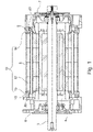
Fig. 1 shows a cross sectional view of components of a fluid cooled electric motor of an embodiment of the present invention, cut along the axis of the electric motor. -
Fig. 2 shows a cross sectional view of a stator core of an embodiment of the present invention, cut perpendicular to the axis. -
Fig. 3 shows an oblique view of components of an embodiment of the present invention. -
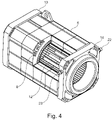
Fig. 4 shows a partially cut-out, oblique view of components of an embodiment of the present invention. -
Figs. 5a and 5b show an oblique view of the cooling system of an embodiment of the present invention. -
Fig. 6 shows a partially cut-out, oblique view showing a portion of an embodiment of the present invention. -
Fig. 7 shows a cooling system according to an aspect of the present invention. -
Fig. 8 shows an exterior view of the electric motor of the present invention. - An embodiment of an electric machine 1 comprising a
fluid cooling system 10 according to the present invention is described in the following with reference to the figures. - As shown in
Fig. 1 , the electric machine 1 of the present embodiment is a water-cooled motor, which is produced from an existing design of an air cooled motor, by adding simple components to the existing design, without requiring modification or replacement of the rotor, stator or end shields of the existing design. Hence, the rotor, stator and end shields of the present embodiment are the same ones used for the existing air-cooled motor. - An oblique view of the exterior of an electric motor is shown in
Fig. 8 . - The electric machine 1 of the present embodiment includes a
shaft 3, arotor 4, astator core 5, a drive-end end shield 6, and a non-drive-end end shield 7. Theshaft 3 is supported by bearings in theend shields end end shield 6. -
Fig. 2 is a cross sectional view of thestator core 5 cut perpendicular to the axis of the machine. As shown inFig. 2 , thestator core 5 of the present embodiment has an inner opening which accommodates the shaft 3 (not shown) and rotor 4 (not shown), and projections which project towards the axis, and support the windings (not shown) of the stator. The outer periphery of thestator core 5 has the shape of a square with truncated corners. Thestator core 5 includes through-holes 8 which extend parallel to the axis of the machine. These through-holes 8 are arranged in the vicinity of the truncated corners of the square cross section. In the present embodiment, there are three through-holes 8 provided near each corner. - In the water-cooled motor of the present embodiment,
pipes 12, which are part of thecooling system 10, are provided in the through-holes 8. Thesepipes 12 provide a fluid-sealed path for flow of the cooling water. In the present embodiment,pipes 12 are included in all three of the through-holes 8 near each corner. -
Fig. 3 is an oblique view showing components of the present embodiment, including thestator core 5, andcollector bodies Fig. 4 shows the same view asFig. 3 , but inFig. 4 part of thestator core 5 is cut away to reveal thepipes 12 inside the stator core. Also, inFig. 4 , parts of the pipes are cut away to reveal the through-holes 8. -
Figs. 5a and 5b are oblique views showing thecooling system 10 of the present embodiment.Fig. 5a shows thecooling system 10 with thecollector body 13 closest to the viewer;Fig. 5b shows thecooling system 10 with thecollector body 14 closest to the viewer. InFigs. 5a and 5b , the portions of thecollector chambers 20 andfluid channels 21 are cut open to illustrate the fluid flow. Fluid is input under pressure into thefluid inlet 22 of thecollector body 14. The means for supplying pressurized cooling fluid to thefluid inlet 22 are provided by the user of the motor, and are not shown. The arrows illustrate the flow of fluid. As shown by the arrows, the cooling fluid flows intofluid inlet 22, and sequentially flows throughcollector chambers pipes 12 andfluid channels 21, and out of thefluid outlet 23. - More specifically, the cooling fluid flows through the
fluid inlet 22 into thefirst collector chamber 20A of thecollector body 14. From thefirst collector chamber 20A, the fluid flows throughpipes 12, into asecond collector chamber 20B of thecollector body 13. From thecollector chamber 20B, the fluid flows through thefluid channel 21 into athird collector chamber 20C ofcollector body 13, and from there flows through thepipes 12 into afourth collector chamber 20D ofcollector body 14. The fluid then continues to flow through other fluid channels, collector chambers, and pipes as illustrated by the arrows, until it reaches thefluid outlet 23. Along this path, the cooling fluid absorbs heat from the stator core 5 (not shown). The warmer fluid emerging from thefluid outlet 23 can be cooled and recirculated to thefluid inlet 22 by a circulating system (not shown) provided by the user of the electric machine. - Thus, the cooling fluid flows axially from
collector chamber 20A ofcollector body 14 tocollector chamber 20B ofcollector body 13 in a first axial direction throughpipes 12. Then the cooling fluid flows throughfluid channel 21 ofcollector body 13, tocollector chamber 20C ofcollector body 13. Fromcollector chamber 20C, the cooling fluid flows throughpipes 12 tocollector chamber 20D ofcollector body 14, in a second axial direction which is opposite to the first axial direction, as shown by the arrows inFig. 5a and 5b . Then, the cooling fluid flows throughfluid channel 21 tocollector chamber 20E, and then flows throughpipes 12 tocollector chamber 20F ofcollector body 13, in the first axial direction. Then, the cooling fluid flows throughfluid channel 21 ofcollector body 13 tocollector chamber 20G ofcollector body 13. Then, the cooling fluid flows fromcollector chamber 20G tocollector chamber 20H ofcollector body 14 in the second axial direction. -
Fig. 6 is an oblique view showing a portion of thecollector body 13 andpipes 12, with a cutout showing thecollector chamber 20 and connectinghole 16 inside thecollector body 13. As shown inFig. 6 , the connectinghole 16 includes agroove 17 for accommodating theseal ring 18. Theseal ring 18 provides a fluid-sealed connection between thepipe 12 and the connectinghole 16. As shown inFig. 6 , one side of the connectinghole 16 opens to the face of thecollector body 13 to allow insertion of thepipes 12, while the other side of the connectinghole 16 opens to thecollector chamber 20, thereby connecting thepipe 12 and thecollector chamber 20 to allow the flow of fluid. - In the following, general (optional) aspects of the invention are described in detail. The description uses reference signs found in the figures, but these reference signs are only used for illustration and the aspects are not limited to the embodiments shown in the figures.
- According to an aspect of the invention, the fluid cooled electric machine can be readily produced based on existing designs of air cooled electric machines. Such existing air-cooled electric machines generally include a shaft extending along an axis of the machine, a rotor rotationally coupled to the shaft, a stator radially surrounding the rotor and having a stator core, and first and second end shields mounted at axially opposite ends of the machine, and the electric machine of the present invention can utilize these components of an air-cooled electric machine without modification.
- One example of such an electric machine of the present invention is an electric motor. Another example is a generator.
- According to an aspect, the
shaft 3 of the fluid cooled electric machine 1 protrudes from the drive end of the electric machine, and rotates about an axis. In the present description, the axis of rotation of the shaft is referred to as the axis of the electric machine, and "axial" or "axially" generally refers to a line which is parallel to the axis of the electric machine. - According to an aspect, the
rotor 4 is rotationally coupled to the shaft, so that the shaft and rotor rotate as a unit. - According to an aspect, the stator radially surrounds the rotor, and includes a
stator core 5. Thestator core 5 includescavities 8 extending axially. Such cavities are generally present in existing designs of air cooled machines, for air cooling. One example of such cavities are through-holes extending axially through thestator core 5. Another example of such cavities are spaces such as axial channels formed between adjacent cooling fins. - According to an aspect,
pipes 12 are inserted into thesecavities 8 for cooling the electric machine. Cooling fluid runs inside thepipes 12 to cool the electric machine. Thepipes 12 are closely in contact with thecavities 8 of thestator core 5, in order to transfer heat from metallic parts, such as lamination sheets of thestator core 5 and thepipes 12, to the cooling fluid. Because thecavities 8 extend axially, it is possible to insert straight pipes. In this way, the present invention does not require cooling pipes having a complicated shape which wrap around the electric machine. - According to an aspect, the shape of the cross section of the outer periphery of the
stator core 5 is not particularly limited, and for example, may be may be round, square, or approximately square, such as a square with rounded corners, or truncated corners as shown inFig. 2 . In this case, the cavities may be preferably arranged near the corners of the square, as shown inFig. 2 , in order to take advantage of the larger available cross-sectional space in this part of the stator. - According to an aspect, the end shields 6,7 of the electric machine are provided at both axial ends of the electric machine. The end shields 6,7 provide a cover for the axial ends of the stator's inner space in which the rotor is provided, while leaving an opening for the shaft, at least at the drive-
end end shield 6, and also strengthen the structure the electrical machine. The drive-end end shield 6 is mounted to the drive end of the electric machine. The non-drive-end end shield 7 is mounted to the non-drive-end of the electric machine. - According to an aspect, the end shields 6,7 generally include bearing seats which rotationally support the rotor. The end shields 6,7 may also have integrated feet, to support the electric machine, and/or a flange for fixing the electric machine to a base plate.
- According to an aspect, in the fluid cooled electric machine of the present invention, the
rotor 4, stator andstator core 5, andend shields - The
fluid cooling system 10 comprisespipes 12, and first andsecond collector bodies collector chambers 20 for the fluid. - According to an aspect, the
fluid cooling system 10 is a stand-alone system. This means that the first andsecond collector bodies pipes 12 are made of separate parts, separate from the other components of the electric machine, to provide a path for fluid flow. Because the fluid cooling system is a stand-alone system, it can be easily added to the components of an existing (e.g., air-cooled) electric machine, without specialized tools. - According to an aspect, the
pipes 12 of the cooling system have a size and shape which allows insertion into theaxial cavities 8, such as through-holes, of thestator core 5. Thepipes 12 preferably have sufficient length so that both ends of eachpipe 12 protrude from thestator core 5 when thepipes 12 are positioned in the axial cavities (through-holes) 8. - In a preferable aspect of the invention, the
pipes 12 are cylindrical. This has the advantage that specially shaped pipes are not required. - According to an aspect, the material for the
pipes 12 is a mainly a material having suitable thermal conductivity. Examples of a suitable material are aluminum alloy, stainless steel or copper and copper nickel alloys. - The number of
pipes 12 used for the fluid cooled electric machine is not particularly limited. For example, the fluid cooling system may include fourpipes 12. If the shape of the cross section of the outer periphery of thestator core 5 is square or approximately square, as shown inFig. 2 , onepipe 12 can be located near each corner of the square. However, to provide higher cooling capacity, two, three ormore pipes 12 could be provided near each corner of the square. Alternatively, the pipe diameter can be increased to provide higher cooling capacity. The shape of the cross section of the outer periphery of thestator core 5 is not limited to a square or approximately square shape, and for example, a round shape may be employed. Other arrangements of thepipes 12 are also possible, such as an even distribution of the pipes around the periphery of the stator core. - The present invention includes two
collector bodies collector body 13 is mounted, as a separate piece, between one end of thestator core 5 and oneend shield 6. Theother collector body 14 is mounted, as a separate piece, between the other end of thestator core 5 and theother end shield 7. - Because the
collector bodies - According to an aspect, the material of the collector body is a material having suitable thermal conductivity. Examples of a suitable material are aluminum alloy or stainless steel.
- The shape of the
collector bodies stator core 5, end shields 6,7, andpipes 12. For example, if the outer periphery of the stator core has an approximately square cross-sectional shape, the collector bodies may also have an outer periphery with a corresponding approximately square cross-sectional shape. However, other shapes such as a round or oval cross sectional shape may also be selected. - Each
collector body collector chambers 20. Eachpipe 12 is mounted in anaxial cavity 8 of thestator core 5, and interconnects acollector chamber 20 of thefirst collector body 13 and acollector chamber 20 of thesecond collector body 14. - In this way, a path can be formed for the cooling fluid to flow from one
collector chamber 20 of onecollector body pipe 12, to theother collector chamber 20 of theother collector body - The number of
collector chambers 20 is not particularly limited. For example, if thestator core 5 has an approximately square cross-sectional shape, and the pipes are arranged near the corners of the square, each collector body may have onecollector chamber 20 near each corner of the square. In this case, each collector body will have a total of 4 collector chambers. - According to an aspect, the
first end 6 shield is mountable to the first end of thestator core 5, and thesecond end shield 7 is mountable to the second end of thestator core 5. In a previously existing design of an air cooled electric machine, which has no fluid cooling system, the end shields are mounted onto the ends of the stator core. In this aspect, thecollector bodies - In this way, the fluid cooled electric machine of the present invention can use the same end shields and the same stator of an existing design of an air cooled electric machine, without modification. This allows a manufacturer of electric machines to flexibly offer both air cooled and fluid cooled electric machines, based on the same air cooled design, at low cost.
- According to an aspect, the first and
second collector bodies holes 16 which connect one end of apipe 12 to thecollector chamber 20 of thefirst collector body 13, and the other end of thepipe 12 to thecollector chamber 20 of thesecond collector body 14. These connectingholes 16 allow for easy connection between thepipes 12 and thecollector chambers 20. - According to an aspect, the pipes and collector bodies are connected in a fluid-sealed state. In the present application, "fluid-sealed" means that cooling fluid can be made to flow under pressure through the cooling system, without leaking to the outside of the cooling system.
- According to an aspect, each connecting
hole 16 comprises aseal ring 18. The seal rings are one means of providing a fluid-sealed connection between thecollector chambers 20 and thepipes 12. A soft material of aseal ring 18 allows and ensures the proper self-alignment between thepipes 12, at their outer diameter, and the connecting holes 16. - According to an aspect, the seal rings are disposed in an
inner groove 17 of the connecting holes 16. Thegrooves 17 hold the seal rings 18 in place. By providing thegrooves 17 in the connectingholes 16, instead of on thepipe 12, it is possible to use pipes having a thinner wall. Thinner pipe walls allow for more efficient heat transfer and better cooling. - The material of the seal rings 18 is not particularly limited, provided that it can form a suitable seal between the connecting
holes 16 and thepipes 12. Examples of suitable materials are synthetic rubbers with good proprieties of compression and heat resistance. - According to an aspect, the connecting
holes 16 are connection openings extending from thecollector chamber 20 to the stator-facing side of therespective collector body pipe 12 is inserted into the connection opening and is thereby connected to thecollector chamber 20. - The number of connecting
holes 16 is not particularly limited. For example, there may be one, two, three or moreconnecting holes 16 provided for onecollector chamber 20. In this way, it is possible to connect more than onepipe 12 to eachcollector chamber 20, which can provide increased flow of cooling fluid. - According to an aspect, the first and
second collector bodies fluid channel 21 which forms a fluid path interconnecting a pair ofcollector chambers 20 of therespective collector body fluid channels 21 for eachcollector body collector body fluid channels 21. - According to an aspect, at least one of the
collector bodies fluid inlet 22 and afluid outlet 23. Thefluid inlet 22 and thefluid outlet 23 may preferably include a plug-in nipple. Thefluid inlet 22 andfluid outlet 23 may be provided on either of thecollector bodies fluid inlet 22 may be provided on one of thecollector bodies fluid outlet 23 may be provided on the other of thecollector bodies - According to an aspect, the position of the
fluid inlet 22 and thefluid outlet 23 can be changed by changing the orientation at which the collector body is mounted to the stator. For example, thefluid inlet 22 and thefluid outlet 23 can be positioned at the upper side of the electric machine, or at the lower side of the electric machine. Also, by reversing thecollector bodies fluid inlet 22 and thefluid outlet 23 can be positioned at the non-drive end or drive end of the electric machine. This allows a flexible positioning offluid inlet 22 and afluid outlet 23, in accordance with pipes provided for cooling fluid at the user's location. - According to an aspect, the cooling fluid is water. Other cooling fluids which can be used are coolant fluids for industrial applications.
- According to an aspect, the
collector bodies pipes 12 form a closed fluid-sealed path extending from thefluid inlet 22, through thecollector bodies pipes 12, to thefluid outlet 23. The number and arrangement ofpipes 12, andcollector chambers 20, connectingholes 16,fluid channels 21 and the like may be suitably set to provide a flow of cooling fluid as required to achieve acceptable cooling performance. - According to an aspect, the fluid flows axially from a
collector chamber 20 of onecollector body collector chamber 20 of theother collector body more pipes 12. Because thepipes 12 are mounted in theaxial cavities 8 of thestator core 5, the fluid flowing through thepipes 12 can cool thestator core 5. - According to an aspect, the fluid flows from one
collector chamber 20 of onecollector body collector chamber 20 of thesame collector body fluid channel 21. In this way thefluid channel 21 can connectcollector chambers 20 of thesame collector body collector bodies stator core 5, and also cool the end shields 6,7. - According to an aspect, the flow of cooling fluid follows a zigzag path from the
fluid inlet 22 to thefluid outlet 23. This means that the fluid flow in the pipe(s) 12 connected to onecollector chamber 20 of onecollector body adjacent collector chambers 20 of thesame collector body first collector chamber 20 of afirst collector body 13 tosecond collector chamber 20 of asecond collector body 14 in a first axial direction (for example, from a drive end to a non-drive end of the electric machine), through one or more pipe(s) 12 connecting the first andsecond collector chambers 20. Then, the fluid flows from thesecond collector chamber 20, through afluid channel 21, to athird collector chamber 20 of thesame collector body 14. Then, the fluid flows axially from thethird collector chamber 20 of thesecond collector body 14 to afourth collector chamber 20 of thefirst collector body 13 in a second axial direction (for example, from a non-drive end to a drive end of the machine) through pipe(s) 12 connecting the third andfourth collector chambers 20. Thefourth collector chamber 20 is adjacent to thefirst collector chamber 20 of thefirst collector body 13, and the second axial direction of fluid flow in thepipes 12 connected to thefourth collector body 20, is opposite to the first axial direction of fluid flow, through thepipes 12 connected to the adjacentfirst collector chamber 20. - By such a flow of cooling fluid, it is possible to efficiently circulate fluid through a large portion of the
stator core 5, and efficiently cool the electric machine. - However, the fluid flow is not limited to the path described above, and the stand-
alone cooling system 10 for cooling fluid flow can flexibly provide other options for cooling fluid flow. For example, as shown inFig. 7 , in another aspect, twocollector bodies collector chambers 20 andfluid channels 21 as shown for thecollector body 13 inFig. 5a . In this case, thefluid inlet 22 andfluid outlet 23 are positioned on thecollector body 13a. Then, by appropriately arranging the orientations of thecollector bodies - Namely, as shown by the arrows in
Fig. 7 , cooling fluid flows through thefluid inlet 22 at the upper side of the electric machine, into afirst collector chamber 201. The cooling fluid will also flow from thecollector chamber 201 to thesecond collector chamber 20J ofcollector body 13a via thefluid channel 21.Collector chambers collector body 13a at the upper side of the electric machine. Fromcollector chambers collector body 13, viapipes 12. The fluid then flows viafluid channels 21 to two collector chambers at the lower side of thecollector body 13. Then, the fluid flows viapipes 12 intocollector chambers collector body 13a, and flows out of thefluid outlet 23 at the lower side of thecollector body 13a. - A method of producing a fluid cooled electric machine according to the present invention comprises the steps of: mounting the
pipes 12 in theaxial cavities 8 of thestator core 5, mounting thefirst collector body 13 to a first end of thestator core 5, and mounting thesecond collector body 14 to a second end of thestator core 5, so that thepipes 12 interconnect thecollector chambers 20 of the first and thesecond collector bodies first end shield 6 to thefirst collector body 13, and mounting thesecond end shield 7 to thesecond collector body 14. In this manner, the cooling system can also be included in an existing (e.g., air-cooled) electric machine. - The present invention provides a fluid cooled electric machine which can be readily manufactured by adding simple components to an existing air cooled design, with a minimum of specialized components or specialized tools, and with simple production steps.
-
- 1
- electric machine
- 3
- shaft
- 4
- rotor core
- 5
- stator core
- 6,7
- end shield
- 8
- cavity
- 10
- fluid cooling system
- 12
- pipe
- 13, 13a, 14
- collector body
- 16
- connecting hole
- 17
- groove
- 18
- seal ring
- 20, 20A ... 20L
- collector chamber
- 21
- fluid channel
- 22
- fluid inlet
- 23
- fluid outlet
Claims (14)
- A fluid cooled electric machine comprising a shaft extending along an axis of the machine, a rotor rotationally coupled to the shaft, a stator radially surrounding the rotor and having a stator core, first and second end shields mounted at opposite ends of the electric machine in the axial direction, and a fluid cooling system for cooling the electric machine,
the stator core having a plurality of axial cavities,
the fluid cooling system comprising:first and second collector bodies, each comprising a plurality of collector chambers for the cooling fluid, anda plurality of pipes, whereinthe first collector body is mounted, as a separate piece, between a first end of the stator core and the first end shield,the second collector body is mounted, as a separate piece, between a second end of the stator core and the second end shield,each pipe is mounted in the axial cavities of the stator core, and interconnects a collector chamber of the first collector body and a collector chamber of the second collector body. - An electric machine according to claim 1, wherein the first end shield is mountable to the first end of the stator core, and the second end shield is mountable to the second end of the stator core.
- An electric machine according to claim 1 or 2, wherein
the first and second collector bodies each comprise connecting holes which connect one end of a pipe to the collector chamber of the first collector body, and the other end of the pipe to the collector chamber of the second collector body. - An electric machine according to any one of claims 1 to 3, wherein the pipes and collector bodies are connected in a fluid-sealed state.
- An electric machine according to claim 3 or 4, wherein each connecting hole comprises a seal ring.
- An electric machine according to any one of claims 3 to 5, wherein each seal ring is disposed in an inner groove of the connecting hole.
- An electric machine according to any one of claims 1 to 6, wherein the pipes are cylindrical.
- An electric machine according to any one of claims 1 to 7, wherein at least one of the collector bodies comprises a fluid inlet and a fluid outlet.
- An electric machine according to any one of claims 1 to 8, wherein the electric machine is an electric motor.
- An electric machine according to any one of claims 1 to 9, wherein the cooling fluid is water.
- An electric machine according to any one of claims 1 to 10, wherein the first and second collector bodies each comprise a fluid channel which forms a fluid path interconnecting a pair of collector chambers of the respective collector body.
- An electric machine according to any one of claims 3 to 11, wherein the connecting holes are connection openings extending from the collector chamber to the stator-facing side of the respective collector body, wherein the pipe is inserted into the connection opening and is thereby connected to the collector chamber.
- An electric machine according to any one of claims 8 to 12, wherein the collector bodies and pipes form a closed fluid-sealed path extending from the fluid inlet, through the collectors and pipe, to the fluid outlet.
- A method of producing a fluid cooled electric machine comprising a fluid cooling system according to any one of claims 1 to 13, comprising the steps of:mounting the pipes in the axial cavities of the stator core,mounting the first collector body to a first end of the stator core, and mounting the second collector body to a second end of the stator core, so that the pipes interconnect the collector chambers of the first and the second collector bodies, andmounting the first end shield to the first collector body, and mounting the second end shield to the second collector body.
Priority Applications (2)
| Application Number | Priority Date | Filing Date | Title |
|---|---|---|---|
| EP21150939.3A EP4027489A1 (en) | 2021-01-11 | 2021-01-11 | Fluid cooled electric machine |
| US17/573,361 US12525840B2 (en) | 2021-01-11 | 2022-01-11 | Fluid cooled electric machine |
Applications Claiming Priority (1)
| Application Number | Priority Date | Filing Date | Title |
|---|---|---|---|
| EP21150939.3A EP4027489A1 (en) | 2021-01-11 | 2021-01-11 | Fluid cooled electric machine |
Publications (1)
| Publication Number | Publication Date |
|---|---|
| EP4027489A1 true EP4027489A1 (en) | 2022-07-13 |
Family
ID=74130120
Family Applications (1)
| Application Number | Title | Priority Date | Filing Date |
|---|---|---|---|
| EP21150939.3A Pending EP4027489A1 (en) | 2021-01-11 | 2021-01-11 | Fluid cooled electric machine |
Country Status (2)
| Country | Link |
|---|---|
| US (1) | US12525840B2 (en) |
| EP (1) | EP4027489A1 (en) |
Cited By (1)
| Publication number | Priority date | Publication date | Assignee | Title |
|---|---|---|---|---|
| EP4451518A1 (en) * | 2023-04-10 | 2024-10-23 | Abb Schweiz Ag | Electric motor coolant frame and header |
Families Citing this family (2)
| Publication number | Priority date | Publication date | Assignee | Title |
|---|---|---|---|---|
| DE102022134605A1 (en) * | 2022-12-22 | 2024-06-27 | Valeo Eautomotive Germany Gmbh | Stator for an electrical machine, electrical machine and method for producing a stator |
| CN117458795B (en) * | 2023-12-13 | 2025-02-07 | 京马电机有限公司 | An optimized structure for external cooling of a motor |
Citations (4)
| Publication number | Priority date | Publication date | Assignee | Title |
|---|---|---|---|---|
| EP1499001A1 (en) * | 2003-07-17 | 2005-01-19 | Jeumont Sa | Cooling arrangement for electrical machines specially for a permanent magnet syncronous machine |
| DE102011076904A1 (en) * | 2011-06-01 | 2012-12-06 | Robert Bosch Gmbh | Stator for electric motor used as electric drive for hybrid vehicle, has stator laminations which are interconnected by cooling element |
| US20150280525A1 (en) * | 2014-03-27 | 2015-10-01 | Prippel Technologies, Llc | Induction motor with transverse liquid cooled rotor and stator |
| EP3079239A1 (en) * | 2015-04-09 | 2016-10-12 | GE Energy Power Conversion Technology Ltd | Stators for electrical machines |
Family Cites Families (8)
| Publication number | Priority date | Publication date | Assignee | Title |
|---|---|---|---|---|
| DE19757605C2 (en) * | 1997-12-23 | 2003-03-13 | Siemens Ag | Electric motor with cooling |
| DE10005128B4 (en) * | 2000-02-07 | 2004-03-25 | Baumüller Nürnberg GmbH | Coolable stand for an electrical machine |
| DE102005002564A1 (en) * | 2005-01-19 | 2006-08-10 | Siemens Ag | Electric drive device with heatpipe cooling |
| DE102006005316B4 (en) * | 2006-02-06 | 2020-03-26 | Siemens Aktiengesellschaft | Cooling device for an electrical machine, electrical machines with such a cooling device, dynamo sheet and manufacturing processes for such electrical machines |
| US8970075B2 (en) * | 2012-08-08 | 2015-03-03 | Ac Propulsion, Inc. | Liquid cooled electric motor |
| CN208638160U (en) * | 2018-07-31 | 2019-03-22 | 沈阳黎明电机制造有限公司 | New-type electric machine cooling shell |
| CN109617292B (en) * | 2019-01-18 | 2020-02-07 | 昆山南洋电机配件有限公司 | Motor cylinder body with water cooling and air cooling functions |
| CN110289723A (en) * | 2019-07-18 | 2019-09-27 | 王胜龙 | A kind of generator casing of good heat dissipation effect |
-
2021
- 2021-01-11 EP EP21150939.3A patent/EP4027489A1/en active Pending
-
2022
- 2022-01-11 US US17/573,361 patent/US12525840B2/en active Active
Patent Citations (4)
| Publication number | Priority date | Publication date | Assignee | Title |
|---|---|---|---|---|
| EP1499001A1 (en) * | 2003-07-17 | 2005-01-19 | Jeumont Sa | Cooling arrangement for electrical machines specially for a permanent magnet syncronous machine |
| DE102011076904A1 (en) * | 2011-06-01 | 2012-12-06 | Robert Bosch Gmbh | Stator for electric motor used as electric drive for hybrid vehicle, has stator laminations which are interconnected by cooling element |
| US20150280525A1 (en) * | 2014-03-27 | 2015-10-01 | Prippel Technologies, Llc | Induction motor with transverse liquid cooled rotor and stator |
| EP3079239A1 (en) * | 2015-04-09 | 2016-10-12 | GE Energy Power Conversion Technology Ltd | Stators for electrical machines |
Cited By (2)
| Publication number | Priority date | Publication date | Assignee | Title |
|---|---|---|---|---|
| EP4451518A1 (en) * | 2023-04-10 | 2024-10-23 | Abb Schweiz Ag | Electric motor coolant frame and header |
| US12587059B2 (en) | 2023-04-10 | 2026-03-24 | Abb Schweiz Ag | Electric motor coolant frame and header |
Also Published As
| Publication number | Publication date |
|---|---|
| US20220224190A1 (en) | 2022-07-14 |
| US12525840B2 (en) | 2026-01-13 |
Similar Documents
| Publication | Publication Date | Title |
|---|---|---|
| US12525840B2 (en) | Fluid cooled electric machine | |
| US7737585B2 (en) | Electric machine with improved water cooling system | |
| CN103155376B (en) | Coolant channel for motor stator | |
| US7579725B2 (en) | Liquid cooled rotor assembly | |
| JP5703698B2 (en) | Rotating machine and vehicle | |
| EP3549242B1 (en) | Electric machine provided with an enclosed cooling assembly paired to an open cooling assembly | |
| WO2021115632A1 (en) | Axial flux motor with cooling jacket | |
| JP2000102216A (en) | Liquid-cooled asynchronous electric machine | |
| JPWO2001018943A1 (en) | Rotating electric machines | |
| EP1037361A1 (en) | AC generator for vehicle | |
| CN115378168A (en) | Rotor assembly and motor comprising same | |
| JP2014087248A (en) | Liquid cooled type rotary electric machine and rotary electric machine system | |
| CN220043162U (en) | Oil-cooled motor device | |
| JP7713397B2 (en) | Rotating electric machine and vehicle drive device equipped with the same | |
| KR102749973B1 (en) | Electric motor and electric vehicle having the same | |
| CN114069938A (en) | Water-gas composite cooling motor structure and new energy automobile using same | |
| KR102821780B1 (en) | Electric motor and electric vehicle having the same | |
| CN222515232U (en) | Motor assembly and vehicle | |
| JP2000295818A (en) | Liquid-cooled rotary electric machine | |
| JP3675363B2 (en) | Rotating electric machine | |
| JPS61170254A (en) | Liquid cooled motor | |
| CN211429059U (en) | Motor case | |
| CN115133717A (en) | Rotary motor | |
| WO2022086459A1 (en) | A liquid - cooled cooling method for electric motors and alternators | |
| CN222802638U (en) | Motor and electric drive system |
Legal Events
| Date | Code | Title | Description |
|---|---|---|---|
| PUAI | Public reference made under article 153(3) epc to a published international application that has entered the european phase |
Free format text: ORIGINAL CODE: 0009012 |
|
| STAA | Information on the status of an ep patent application or granted ep patent |
Free format text: STATUS: THE APPLICATION HAS BEEN PUBLISHED |
|
| AK | Designated contracting states |
Kind code of ref document: A1 Designated state(s): AL AT BE BG CH CY CZ DE DK EE ES FI FR GB GR HR HU IE IS IT LI LT LU LV MC MK MT NL NO PL PT RO RS SE SI SK SM TR |
|
| STAA | Information on the status of an ep patent application or granted ep patent |
Free format text: STATUS: REQUEST FOR EXAMINATION WAS MADE |
|
| 17P | Request for examination filed |
Effective date: 20230113 |
|
| RBV | Designated contracting states (corrected) |
Designated state(s): AL AT BE BG CH CY CZ DE DK EE ES FI FR GB GR HR HU IE IS IT LI LT LU LV MC MK MT NL NO PL PT RO RS SE SI SK SM TR |
|
| STAA | Information on the status of an ep patent application or granted ep patent |
Free format text: STATUS: EXAMINATION IS IN PROGRESS |
|
| 17Q | First examination report despatched |
Effective date: 20250326 |