EP4027470A1 - Corrugated-tube protective member - Google Patents
Corrugated-tube protective member Download PDFInfo
- Publication number
- EP4027470A1 EP4027470A1 EP22150006.9A EP22150006A EP4027470A1 EP 4027470 A1 EP4027470 A1 EP 4027470A1 EP 22150006 A EP22150006 A EP 22150006A EP 4027470 A1 EP4027470 A1 EP 4027470A1
- Authority
- EP
- European Patent Office
- Prior art keywords
- pair
- dividing surface
- main body
- dividing
- corrugated
- Prior art date
- Legal status (The legal status is an assumption and is not a legal conclusion. Google has not performed a legal analysis and makes no representation as to the accuracy of the status listed.)
- Withdrawn
Links
- 230000001681 protective effect Effects 0.000 title claims abstract description 32
- 230000008878 coupling Effects 0.000 description 5
- 238000010168 coupling process Methods 0.000 description 5
- 238000005859 coupling reaction Methods 0.000 description 5
- 238000003780 insertion Methods 0.000 description 4
- 230000037431 insertion Effects 0.000 description 4
- 230000002093 peripheral effect Effects 0.000 description 3
- 230000005489 elastic deformation Effects 0.000 description 1
- 239000011810 insulating material Substances 0.000 description 1
- 238000000034 method Methods 0.000 description 1
- 238000012986 modification Methods 0.000 description 1
- 230000004048 modification Effects 0.000 description 1
- 230000001012 protector Effects 0.000 description 1
- 230000000717 retained effect Effects 0.000 description 1
- 229920003002 synthetic resin Polymers 0.000 description 1
- 239000000057 synthetic resin Substances 0.000 description 1
Images



Classifications
-
- F—MECHANICAL ENGINEERING; LIGHTING; HEATING; WEAPONS; BLASTING
- F16—ENGINEERING ELEMENTS AND UNITS; GENERAL MEASURES FOR PRODUCING AND MAINTAINING EFFECTIVE FUNCTIONING OF MACHINES OR INSTALLATIONS; THERMAL INSULATION IN GENERAL
- F16L—PIPES; JOINTS OR FITTINGS FOR PIPES; SUPPORTS FOR PIPES, CABLES OR PROTECTIVE TUBING; MEANS FOR THERMAL INSULATION IN GENERAL
- F16L57/00—Protection of pipes or objects of similar shape against external or internal damage or wear
- F16L57/005—Protection of pipes or objects of similar shape against external or internal damage or wear specially adapted for the ends of pipes
-
- H—ELECTRICITY
- H02—GENERATION; CONVERSION OR DISTRIBUTION OF ELECTRIC POWER
- H02G—INSTALLATION OF ELECTRIC CABLES OR LINES, OR OF COMBINED OPTICAL AND ELECTRIC CABLES OR LINES
- H02G3/00—Installations of electric cables or lines or protective tubing therefor in or on buildings, equivalent structures or vehicles
- H02G3/02—Details
- H02G3/04—Protective tubing or conduits, e.g. cable ladders or cable troughs
- H02G3/0462—Tubings, i.e. having a closed section
- H02G3/0468—Corrugated
-
- H—ELECTRICITY
- H02—GENERATION; CONVERSION OR DISTRIBUTION OF ELECTRIC POWER
- H02G—INSTALLATION OF ELECTRIC CABLES OR LINES, OR OF COMBINED OPTICAL AND ELECTRIC CABLES OR LINES
- H02G1/00—Methods or apparatus specially adapted for installing, maintaining, repairing or dismantling electric cables or lines
- H02G1/06—Methods or apparatus specially adapted for installing, maintaining, repairing or dismantling electric cables or lines for laying cables, e.g. laying apparatus on vehicle
- H02G1/08—Methods or apparatus specially adapted for installing, maintaining, repairing or dismantling electric cables or lines for laying cables, e.g. laying apparatus on vehicle through tubing or conduit, e.g. rod or draw wire for pushing or pulling
-
- H—ELECTRICITY
- H02—GENERATION; CONVERSION OR DISTRIBUTION OF ELECTRIC POWER
- H02G—INSTALLATION OF ELECTRIC CABLES OR LINES, OR OF COMBINED OPTICAL AND ELECTRIC CABLES OR LINES
- H02G3/00—Installations of electric cables or lines or protective tubing therefor in or on buildings, equivalent structures or vehicles
- H02G3/02—Details
- H02G3/04—Protective tubing or conduits, e.g. cable ladders or cable troughs
- H02G3/0406—Details thereof
-
- H—ELECTRICITY
- H02—GENERATION; CONVERSION OR DISTRIBUTION OF ELECTRIC POWER
- H02G—INSTALLATION OF ELECTRIC CABLES OR LINES, OR OF COMBINED OPTICAL AND ELECTRIC CABLES OR LINES
- H02G3/00—Installations of electric cables or lines or protective tubing therefor in or on buildings, equivalent structures or vehicles
- H02G3/02—Details
- H02G3/04—Protective tubing or conduits, e.g. cable ladders or cable troughs
- H02G3/0406—Details thereof
- H02G3/0418—Covers or lids; Their fastenings
-
- H—ELECTRICITY
- H02—GENERATION; CONVERSION OR DISTRIBUTION OF ELECTRIC POWER
- H02G—INSTALLATION OF ELECTRIC CABLES OR LINES, OR OF COMBINED OPTICAL AND ELECTRIC CABLES OR LINES
- H02G3/00—Installations of electric cables or lines or protective tubing therefor in or on buildings, equivalent structures or vehicles
- H02G3/02—Details
- H02G3/06—Joints for connecting lengths of protective tubing or channels, to each other or to casings, e.g. to distribution boxes; Ensuring electrical continuity in the joint
- H02G3/0616—Joints for connecting tubing to casing
- H02G3/0691—Fixing tubing to casing by auxiliary means co-operating with indentations of the tubing, e.g. with tubing-convolutions
Definitions
- the present invention relates to a corrugated-tube protective member.
- a corrugated-tube protective member having a tubular shape configured to be arranged at an inner circumference of an end part of a corrugated tube and configured to insert an electric wire through a tubular portion as a main body is known (see Japanese Patent Laid-Open No. 2019-75946 ).
- a dividing portion dividing the tubular portion in a circumferential direction is provided at one portion in the circumferential direction of the tubular portion.
- the dividing portion is provided with an engagement portion for holding the divided surfaces facing each other in the circumferential direction of the tubular portion.
- the engagement portion has a coupling recess as a locked part and a coupling projection as a locking part formed to be elastically deformable and configured to engage with the coupling recess.
- an electric wire is arranged inside the tubular portion in a state where the tubular portion is divided in the circumferential direction at the dividing portion.
- the tubular shape of the tubular portion is held by engaging the coupling recess and the coupling projection in a state where the dividing surfaces facing each other in the circumferential direction are engaged, and the electric wire is inserted through the tubular portion.
- a dividing surfaces facing in the circumferential direction of the main body is formed linearly along a longitudinal direction of the main body in the dividing portion.
- An elastically deformable locking part is largely exposed to the dividing surface, which is linearly divided.
- an external force may be applied to the locking part, such as interference of the locking part with a peripheral member.
- an external force is applied to the locking part, deformation or damage may occur to the locking part, and the engagement at the engagement portion may become unstable.
- One or more aspects of the present invention are directed to providing a corrugated-tube protective member configured to stabilize the engagement at an engagement portion.
- a corrugated-tube protective member includes a main body with a tubular shape configured to be arranged at an inner circumference of an end part of a corrugated tube and configured to insert an electric wire through the main body. At least one portion in a circumferential direction of the main body is provided with a dividing portion dividing the main body in the circumferential direction. The dividing portion is provided with an engagement portion, the engagement portion being a portion configured to hold a first dividing surface and a second dividing surface facing each other in circumferential direction of the main body in an engaged state.
- the engagement portion comprises a locked part and a locking part formed to be elastically deformed and configured to engage with the locked part.
- the first dividing surface includes at least a first top part protruding toward the second dividing surface side.
- the second dividing surface includes a second bottom part indented to an opposite side of the first dividing surface and configured to engage with the first top part.
- the locked part is formed on the first top part.
- the locking part is formed on the second bottom part.
- the first dividing surface may further include a pair of first bottom parts arranged on both sides of the first top part and indented to an opposite side of the second dividing surface.
- the second dividing surface may further include a pair of second top parts arranged on both sides of the second bottom part and protruding toward the first dividing surface side and is configured to engage with the pair of first bottom parts.
- a tip of the locking part on the first-dividing-surface side may be formed to be on the second-bottom-part side relative to a tip of the pair of second top parts.
- first top part, the pair of first bottom parts, the second bottom part, and the pair of second top parts may be formed of curved surfaces.
- first top part and the pair of first bottom parts may be connected by a pair of first inclined surfaces inclined in a symmetrical shape and the second bottom part and the pair of second top parts may be connected by a pair of second inclined surfaces configured to engage with the pair of first inclined surfaces.
- a corrugated-tube protective member configured to stabilize the engagement at the engagement portion.
- the corrugated-tube protective member 1 is provided with a main body 7 with a tubular shape configured to be arranged at an inner circumference of an end part of a corrugated tube 3 and configured to insert an electric wire 5 through the main body 7. At least one portion in a circumferential direction of the main body 7 is provided with a dividing portion 9 dividing the main body 7 in the circumferential direction.
- the dividing portion 9 is provided with an engagement portion 15, the engagement portion 15 being a portion configured to hold a first dividing surface 11 and a second dividing surface 13 facing each other in a circumferential direction of the main body 7 in an engaged state.
- the engagement portion 15 has a locked part 17 and a locking part 19 formed to be elastically deformed and configured to engage with the locked part 17.
- first dividing surface 11 includes at least a first top part 21 projecting toward the second dividing surface 13 side.
- the second dividing surface 13 includes a second bottom part 23 indented to an opposite side of the first dividing surface 11 and configured to engage with the first top part 21.
- the locked portion 17 is formed on the first top part 21, and the locking part 19 is formed on the second bottom part 23.
- the first dividing surface 11 further includes a pair of first bottom parts 25 arranged on both sides of the first top part 21 and indented to a side opposite to the second dividing surface 13.
- the second divided surface 13 further includes a pair of second top parts 27 arranged on both sides of the second bottom part 23 and protruding toward the first dividing surface 11 side and is configured to engage with the pair of first bottom parts 25.
- a tip of the locking part 19 on the first dividing surface 11 side is formed to be on the second bottom part 23 side relative to a tip of the pair of second top parts 27.
- the first top part 21, the pair of first bottom parts 25, the second bottom part 23, and the pair of second top parts 27 are formed of curved surfaces.
- first top part 21 and the pair of first bottom parts 25 are connected by a pair of first inclined surfaces 29 inclined in a symmetrical shape.
- the second bottom part 23 and the pair of second top parts 27 are connected by a pair of second inclined surfaces 31 configured to engage with the pair of first inclined surfaces 29.
- the corrugated tube 3 has a plurality of ridge portions 33 disposed along a longitudinal direction.
- the corrugated tube 3 is flexible.
- the corrugated tube 3 prevent interference between an electric wire 5 ( see FIG. 5 ) and a peripheral member in a state that the electric wire 5 for electrically connecting a power source and an apparatus mounted on a vehicle is inserted through the corrugated tube 3, for example.
- a slit (not illustrated) into which an electric wire 5 can be inserted is formed along the longitudinal direction of the corrugated tube 3.
- the corrugated tube 3 can be attached to an intermediate portion of the electric wire 5 even in a state the electric wire 5 is routed in a vehicle.
- the corrugated tube 3 may not be provided with a slit.
- the corrugated tube 3 When an external force is applied to the corrugated tube 3 from the outside in the radial direction, the corrugated tube 3 may be deformed so as to collapse toward the inside. In particular, if deformation occurs at the end part of the corrugated tube 3, the corrugated tube 3 may not be attached to a mounting member (not illustrated) such as a protector on which the electric wire 5 is routed. Therefore, the corrugated-tube protective member 1 is arranged at the inner circumference of the end part of the corrugated tube 3.
- the corrugated-tube protective member 1 is made of an insulating material such as synthetic resin having rigidity higher than rigidity of the corrugated tube 3.
- the corrugated-tube protective member 1 includes a main body 7, a rib 35, and a stopper 37.
- the main body 7 is formed into a tubular shape having an outer diameter smaller than an inner diameter of the corrugated tube 3 and configured to be inserted into the corrugated tube 3.
- the main body 7 is divided in the circumferential direction at one dividing portion 9 in the circumferential direction so as to have a first dividing surface 11 and a second dividing surface 13 opposed to each other in the circumferential direction.
- a part opposed to the dividing portion 9 in the radial direction is connected via a hinge 39 so as the main body 7 to open and close.
- the corrugated-tube protective member 1 can be attached to the intermediate portion of the electric wire 5 even in a state the electric wire 5 is routed in the vehicle.
- the main body 7 is held in a state where the first dividing surface 11 and the second dividing surface 13 of the dividing portion 9 is engaged through the engagement portion 15.
- the rib 35 and the stopper 37 are provided on the outer circumference of the main body 7.
- the rib 35 is provided on the outer circumference of the main body 7 continuous in the circumferential direction of the main body 7 and protrudes from the outer circumferential surface of the main body 7 toward the outside.
- the rib 9 and the main body 7 are formed as a single member being continuous with each other.
- An outer diameter of the rib 35 is set smaller than the outer diameter of the ridge portion 33 of the corrugated tube 3.
- the rib 35 is disposed inside the ridge portion 33 in a state the main body 7 is inserted into the inner circumference of the end part of the corrugated tube 3.
- the surface of the rib 35 in the direction of removal of the main body 7 with respect to the corrugated tube 3 is a contacted surface 41 formed substantially perpendicular to the outer circumferential surface of the main body 7.
- the contacted surface 41 is configured to engage with an inner surface facing the contacted surface 41 on the inner circumference of the ridge portion 33 inside the ridge portion 33.
- the main body 7 is prevented from coming off the corrugated tube 3 by the engagement of the rib 35 and the ridge portion 33.
- a plurality of ribs 35 (three ribs in this embodiment) are provided along the longitudinal direction of the main body 7. By providing a plurality of ribs 35 as described above, a plurality of engagement portions between the ribs 35 and the ridge portions 33 can be obtained, and the corrugated-tube protective member 1 can be stably held on the corrugated tube 3.
- the surface of the rib 35 in the insertion direction of the main body 7 into the corrugated tube 3 is an inclined surface 43 inclined upward from the front side in the insertion direction toward the rear side in the insertion direction with respect to the outer circumferential surface of the main body 7. That is, the inclined surface 43 is inclined so as to increase the outer diameter of the corrugated-tube protective member 1 from the front side toward the rear side in the insertion direction.
- the stopper 37 is provided on the outer circumference of the end part of the main body 7 continuous in the circumferential direction of the main body 7 and protrudes from the outer circumferential surface of the main body 7 toward the outside.
- the stopper 11 and the main body 7 are formed as a single member being continuous with each other.
- An outer diameter of the stopper 37 is set equal to or larger than the outer diameter of the ridge portion 33 of the corrugated tube 3. In some embodiments, the outer diameter of the stopper 37 may be set equal to the outer diameter of the ridge portion 33 of the corrugated tube 3.
- the stopper 37 is exposed from the corrugated tube 3 in a state that the main body 7 is inserted into the inner circumference of the end part of the corrugated tube 3, and is arranged to face the end surface in the longitudinal direction of the corrugated tube 3.
- the stopper 37 By arranging the stopper 37 in a manner described above, the stopper 37 abuts the end surface of the corrugated tube 3, when the main body 7 is to be excessively inserted into the corrugated tube 3. The main body 7 can be prevented from being excessively inserted into the corrugated tube 3 by abutting the stopper 37 with the end face of the corrugated tube 3.
- the engaged state of the first dividing surface 11 and the second dividing surface 13 is configured to be hold by the engagement portion 15.
- the engagement portion 15 includes a locked part 17 provided formed on the first divided surface 11 side and a locking part 19 provided on the second divided surface 13 side.
- the locked part 17 is formed protrudes outwardly from the outer surface of the main body 7 on the first divided surface 11 side.
- the locked part 17 and the main body 7 are formed as a single member being continuous with each other.
- the surface of the locked part 17 on the second divided surface 13 side is an inclined surface, and the surface on the first divided surface 11 side is a contacting surface, the contacting surface formed vertically from the outer surface of the main body 7.
- the locking part 19 is formed to be elastically deformable on the second dividing surface 13 side, and extends in a frame-like shape configured to engage with the locked portion 17 toward the first divided surface 11 side.
- the locking part 19 and the main body 7 are formed as a single member being continuous with each other. When closing the main body 7 in a manner that the first dividing surface 11 and the second dividing surface 13 are in a process of engaging each other, the locking part 19 slides onto the inclined surface of the locked part 17 and the locking part 19 is elastically deformed.
- the locking part 19 is restored from the elastic deformation and engaged with the contacting surface of the locked part 17.
- the state in which the first dividing surface 11 and the second dividing surface 13 engage each other that is, the state in which the main body 7 is closed and the main body 7 is in an annular state is retained.
- the exposure amount of the locking part 19 from the second dividing surface 13 increases in order to be engaged with the locked part 17 positioned on the side of the first dividing surface 11.
- the exposure of the locking part 19, which is elastically deformable is large, a possibility that an external force is applied to the locking part 19 increases, and the locking part 19 may interfere with a peripheral member in a state where the main body 7 is opened.
- an external force is applied to the locking part 19, deformation or damage may occur to the locking part 19, and engagement in the engagement portion 15 may become unstable.
- the first dividing surface 11 has the first top part 21, the pair of first bottom parts 25, and the pair of first inclined surfaces 29.
- the second dividing surface 13 has the second bottom part 23, the pair of second top parts 27, and the pair of second inclined surfaces 31.
- the first top part 21 is disposed at a center portion in the longitudinal direction of the main body 7 on the first dividing surface 11.
- the first top part 21 is formed as a single member being continuous with the main body 7 and protrudes toward the second dividing surface 13 side.
- a tip side of the first top part 21 is formed of a curved surface.
- the pair of first bottom parts 25 are disposed on both sides of the first top part 21 with respect to the longitudinal direction of the main body 7 on the first dividing surface 11.
- the pair of first bottom parts 25 are indented to the opposite side of the second dividing surface 13 in the main body 7. Bottom sides of the pair of first bottom parts 25 are formed of curved surfaces.
- the pair of first inclined surfaces 29 respectively connect the first top part 21 and the pair of first bottom parts 25 on the first dividing surface 11.
- the pair of first inclined surfaces 29 are inclined with respect to the longitudinal direction of the main body 7 so as to form a symmetrical shape with the first top part 21 as a symmetry plane.
- the locked part 17 is formed on the first top part 21 protruding toward the second dividing surface 13 side. Therefore, in a state where the main body 7 is closed, since the locked part 17 is disposed adjacent on the second dividing surface 13 side, the amount of protrusion of the locking part 19 formed to be elastically deformable toward the first dividing surface 11 side can be reduced.
- the second bottom part 23 is disposed at a center portion in the longitudinal direction of the main body 7 on the second dividing surface 13.
- the second bottom part 23 is formed so as to be indented to the side opposite to the first dividing surface 11 with respect to the main body 7, and is configured to be engaged with the first top part 21 in a state where the main body 7 is closed.
- a bottom side of the second bottom part 23 is formed of a curved surface.
- the pair of second top parts 27 are disposed on both sides of the second bottom part 23 with respect to the longitudinal direction of the main body 7 on the second dividing surface 13.
- the pair of second top parts 27 are formed as a single member being continuous with the main body 7 and protrudes toward the first dividing surface 11 side, and is configured to be engaged with the pair of first bottom parts 25 in a state where the main body 7 is closed. Tips of the pair of second top parts 27 are formed of curved surfaces.
- the pair of second inclined surfaces 31 respectively connect the second bottom part 23 and the pair of second top parts 27 on the second dividing surface 13.
- the pair of second inclined surfaces 31 are inclined with respect to the longitudinal direction of the main body 7 so as to form a symmetrical shape with the second bottom part 23 as a symmetry plane, and is configured to be engaged with the pair of first inclined surfaces 29 in a state where the main body 7 is closed.
- the locking part 19 is formed on the second bottom part 23 at a position retreat from the first dividing surface 11 side. Therefore, in a state that the main body 7 is opened, the exposure amount of the locking part 19 reduces, and the application of external force to the locking part 19 can be prevented.
- the tip of the locking part 19 on the first dividing surface 11 side is formed to be on the second bottom part 23 side relative to the tip of the pair of second top parts 27. Therefore, the locking part 19 is in a state where the main body 7 is arranged around the locking part 19 and does not expose from the pair of second top parts 27, and the locking part 19 can be further protected.
- first dividing surface 11 and the second dividing surface 13 are formed linearly, there is a possibility that the electric wire 5 gets on the first dividing surface 11 or the second dividing surface 13, and there is a possibility that the electric wire 5 gets caught when the main body 7 is closed.
- the first dividing surface 11 has a first top part 21, and the second dividing surface 13 has a second bottom part 23. That is, the first dividing surface 11 and the second dividing surface 13 are not linearly formed. Therefore, even if the electric wire 5 gets on the first dividing surface 11 or the second dividing surface 13, the electric wire 5 returns to the inner side of the main body 7 or, as illustrated in FIG. 5 , the electric wire 5 comes out to the outside of the main body 7 and can be visually checked. By forming the first dividing surface 11 and the second dividing surface 13 in this manner, the electric wire 5 is prevented from getting on the first dividing surface 11 or the second dividing surface 13, and to prevent the electric wire 5 from being caught when the main body 7 is closed.
- first top part 21, the pair of first bottom parts 25, the second bottom part 23, and the pair of second top parts 27 are formed linearly or sharply, there is a possibility that the electric wire 5 is caught on the linear surface or on the sharp portion.
- the first top part 21, the pair of first bottom parts 25, the second bottom part 23, and the pair of second top parts 27 are formed of curved surfaces. Therefore, the electric wire 5 is prevented from getting on or from being caught on the first top part 21, the pair of the first bottom parts 25, the second bottom part 23, and the pair of the second top parts 27.
- the first top part 21 and the pair of first bottom parts 25 are connected by the pair of first inclined surfaces 29 inclined symmetrically.
- the second bottom part 23 and the pair of second top parts 27 are connected by the pair of second inclined surfaces 31 configured to engage with the pair of first inclined surfaces 29. Therefore, the electric wire 5 can be prevented from remaining on the pair of first inclined surfaces 29 and the pair of second inclined surfaces 31, and the electric wire 5 can be prevented from being caught.
- the locked portion 17 is formed on the first top part 21, and the locking portion 19 is formed on the second bottom part 23. Therefore, in a state where the first dividing surface 11 and the second dividing surface 13 engage each other, since the locked portion 17 is disposed adjacent on the second dividing surface 13 side, the amount of protrusion of the locking part 19 toward the first dividing surface 11 side can be reduced. In addition, in the state where the second dividing surface 13 is opened, the locking part 19, which is elastically deformable, is arranged at the retracted position of the second dividing surface 13, so that the exposure amount of the locking part 19 can be reduced, and the application of external force to the locking part 19 can be prevented.
- the first dividing surface 11 has the first top part 21, and the second dividing surface 13 has the second bottom portion 23. Therefore, the first dividing surface 11 and the second dividing surface 13 are not formed linearly, and the electric wire 5 can hardly get on the first dividing surface 11 and the second dividing surface 13, and the electric wire 5 can be prevented from being caught between the first dividing surface 11 and the second dividing surface 13.
- the tip of the locking part 19 on the first dividing surface 11 side is formed to be on the second bottom portion 23 side relative to a tip of the pair of second top parts 27. Therefore, the locking part 19 is not exposed from the pair of second top parts 27. Therefore, when the second dividing surface 13 is opened, the main body 7 is arranged around the locking part 19, and the locking part 19 can be further protected.
- the first top part 21, the pair of first bottom parts 25, the second bottom part 23, and the pair of second top parts 27 are formed by curved surfaces. Therefore, the electric wire 5 is prevented from getting on or from being caught on the first top part 21, the pair of first bottom parts 25, the second bottom part 23, and the pair of second top parts 27, and to prevent the electric wire 5 from being caught between the first dividing surface 11 and the second dividing surface 13.
- first top part 21 and the pair of first bottom parts 25 are connected by the pair of first inclined surfaces 29 inclined symmetrically.
- the second bottom part 23 and the pair of second top parts 27 are connected by the pair of second inclined surfaces 31 configured to engage with the pair of first inclined surfaces 29. Therefore, the electric wire 5 can be prevented from remaining on the pair of first inclined surfaces 29 or the pair of second inclined surfaces 31, and the electric wire 5 can be prevented from being caught between the first dividing surface 11 and the second dividing surface 13.
- one dividing portion 9 is provided in the circumferential direction of the main body 7, but the present invention is not limited thereto, and two or more dividing portions may be provided in the circumferential direction of the main body.
- an engagement portion may be provided in each of the dividing portions.
- a plurality of engagement portions may be provided for one dividing portion.
- first top part 21 and the second bottom part 23 are provided with one each for the first dividing surface 11 and the second dividing surface 13
- the first top part and the second bottom part may be provided with two or more each for the first dividing surface and the second dividing surface.
Landscapes
- Engineering & Computer Science (AREA)
- Architecture (AREA)
- Civil Engineering (AREA)
- Structural Engineering (AREA)
- General Engineering & Computer Science (AREA)
- Mechanical Engineering (AREA)
- Details Of Indoor Wiring (AREA)
- Protection Of Pipes Against Damage, Friction, And Corrosion (AREA)
Abstract
Description
- The present invention relates to a corrugated-tube protective member.
- Conventionally, a corrugated-tube protective member having a tubular shape configured to be arranged at an inner circumference of an end part of a corrugated tube and configured to insert an electric wire through a tubular portion as a main body is known (see
Japanese Patent Laid-Open No. 2019-75946 - The dividing portion is provided with an engagement portion for holding the divided surfaces facing each other in the circumferential direction of the tubular portion. The engagement portion has a coupling recess as a locked part and a coupling projection as a locking part formed to be elastically deformable and configured to engage with the coupling recess.
- In such a corrugated-tube protective member, an electric wire is arranged inside the tubular portion in a state where the tubular portion is divided in the circumferential direction at the dividing portion. The tubular shape of the tubular portion is held by engaging the coupling recess and the coupling projection in a state where the dividing surfaces facing each other in the circumferential direction are engaged, and the electric wire is inserted through the tubular portion.
- In the conventional corrugated-tube protective member, a dividing surfaces facing in the circumferential direction of the main body is formed linearly along a longitudinal direction of the main body in the dividing portion. An elastically deformable locking part is largely exposed to the dividing surface, which is linearly divided.
- Therefore, when the main body is circumferentially divided by the dividing portion, an external force may be applied to the locking part, such as interference of the locking part with a peripheral member. When an external force is applied to the locking part, deformation or damage may occur to the locking part, and the engagement at the engagement portion may become unstable.
- One or more aspects of the present invention are directed to providing a corrugated-tube protective member configured to stabilize the engagement at an engagement portion.
- A corrugated-tube protective member according to the present invention includes a main body with a tubular shape configured to be arranged at an inner circumference of an end part of a corrugated tube and configured to insert an electric wire through the main body. At least one portion in a circumferential direction of the main body is provided with a dividing portion dividing the main body in the circumferential direction. The dividing portion is provided with an engagement portion, the engagement portion being a portion configured to hold a first dividing surface and a second dividing surface facing each other in circumferential direction of the main body in an engaged state. The engagement portion comprises a locked part and a locking part formed to be elastically deformed and configured to engage with the locked part. The first dividing surface includes at least a first top part protruding toward the second dividing surface side. The second dividing surface includes a second bottom part indented to an opposite side of the first dividing surface and configured to engage with the first top part. The locked part is formed on the first top part. The locking part is formed on the second bottom part.
- In some embodiments, the first dividing surface may further include a pair of first bottom parts arranged on both sides of the first top part and indented to an opposite side of the second dividing surface. The second dividing surface may further include a pair of second top parts arranged on both sides of the second bottom part and protruding toward the first dividing surface side and is configured to engage with the pair of first bottom parts. A tip of the locking part on the first-dividing-surface side may be formed to be on the second-bottom-part side relative to a tip of the pair of second top parts.
- In some embodiments, the first top part, the pair of first bottom parts, the second bottom part, and the pair of second top parts may be formed of curved surfaces.
- In some embodiments, the first top part and the pair of first bottom parts may be connected by a pair of first inclined surfaces inclined in a symmetrical shape and the second bottom part and the pair of second top parts may be connected by a pair of second inclined surfaces configured to engage with the pair of first inclined surfaces.
- According to the above configuration, a corrugated-tube protective member configured to stabilize the engagement at the engagement portion is provided.
-
-
FIG. 1 is a side view of a corrugated-tube protective member according to one or more embodiments in a state the corrugated-tube protective member is attached to a corrugated tube; -
FIG. 2 is a perspective view of the corrugated-tube protective member according to one or more embodiments; -
FIG. 3 is a side view of the corrugated-tube protective member according to one or more embodiments; -
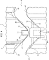
FIG. 4 is a detailed view of the corrugated-tube protective member according to the present embodiment; and -
FIG. 5 is a perspective view of the corrugated-tube protective member according to one or more embodiments in a state an electric wire is exposed from the corrugated-tube protective member. - Various embodiments will be described hereinafter with reference to the accompanying drawings.
- Hereinafter, the corrugated-tube protective member according to one or more embodiments will be described in detail with reference to the drawings. The dimensional ratio of the drawings is may differ from the actual ratio.
- The corrugated-tube
protective member 1 is provided with amain body 7 with a tubular shape configured to be arranged at an inner circumference of an end part of acorrugated tube 3 and configured to insert anelectric wire 5 through themain body 7. At least one portion in a circumferential direction of themain body 7 is provided with a dividingportion 9 dividing themain body 7 in the circumferential direction. - Further, the dividing
portion 9 is provided with anengagement portion 15, theengagement portion 15 being a portion configured to hold a first dividingsurface 11 and a second dividingsurface 13 facing each other in a circumferential direction of themain body 7 in an engaged state. Theengagement portion 15 has a lockedpart 17 and alocking part 19 formed to be elastically deformed and configured to engage with the lockedpart 17. - Further, the first dividing
surface 11 includes at least a firsttop part 21 projecting toward the second dividingsurface 13 side. The second dividingsurface 13 includes asecond bottom part 23 indented to an opposite side of the first dividingsurface 11 and configured to engage with the firsttop part 21. - The locked
portion 17 is formed on the firsttop part 21, and thelocking part 19 is formed on thesecond bottom part 23. - The first dividing
surface 11 further includes a pair offirst bottom parts 25 arranged on both sides of the firsttop part 21 and indented to a side opposite to the second dividingsurface 13. Further, the second dividedsurface 13 further includes a pair of secondtop parts 27 arranged on both sides of thesecond bottom part 23 and protruding toward the first dividingsurface 11 side and is configured to engage with the pair offirst bottom parts 25. - A tip of the
locking part 19 on the first dividingsurface 11 side is formed to be on thesecond bottom part 23 side relative to a tip of the pair of secondtop parts 27. - The first
top part 21, the pair offirst bottom parts 25, thesecond bottom part 23, and the pair of secondtop parts 27 are formed of curved surfaces. - Further, the first
top part 21 and the pair offirst bottom parts 25 are connected by a pair of firstinclined surfaces 29 inclined in a symmetrical shape. Thesecond bottom part 23 and the pair of secondtop parts 27 are connected by a pair of secondinclined surfaces 31 configured to engage with the pair of firstinclined surfaces 29. - As illustrated in
FIG. 1 , thecorrugated tube 3 has a plurality ofridge portions 33 disposed along a longitudinal direction. Thecorrugated tube 3 is flexible. Thecorrugated tube 3 prevent interference between an electric wire 5 ( seeFIG. 5 ) and a peripheral member in a state that theelectric wire 5 for electrically connecting a power source and an apparatus mounted on a vehicle is inserted through thecorrugated tube 3, for example. - In the
corrugated tube 3, a slit (not illustrated) into which anelectric wire 5 can be inserted is formed along the longitudinal direction of thecorrugated tube 3. By forming the slit as described above, thecorrugated tube 3 can be attached to an intermediate portion of theelectric wire 5 even in a state theelectric wire 5 is routed in a vehicle. In some embodiments, thecorrugated tube 3 may not be provided with a slit. - When an external force is applied to the
corrugated tube 3 from the outside in the radial direction, thecorrugated tube 3 may be deformed so as to collapse toward the inside. In particular, if deformation occurs at the end part of thecorrugated tube 3, thecorrugated tube 3 may not be attached to a mounting member (not illustrated) such as a protector on which theelectric wire 5 is routed. Therefore, the corrugated-tubeprotective member 1 is arranged at the inner circumference of the end part of thecorrugated tube 3. - As illustrated in
FIGS. 1 to 5 , the corrugated-tubeprotective member 1 is made of an insulating material such as synthetic resin having rigidity higher than rigidity of thecorrugated tube 3. The corrugated-tubeprotective member 1 includes amain body 7, arib 35, and astopper 37. - The
main body 7 is formed into a tubular shape having an outer diameter smaller than an inner diameter of thecorrugated tube 3 and configured to be inserted into thecorrugated tube 3. Themain body 7 is divided in the circumferential direction at one dividingportion 9 in the circumferential direction so as to have a first dividingsurface 11 and a second dividingsurface 13 opposed to each other in the circumferential direction. In themain body 7, a part opposed to the dividingportion 9 in the radial direction is connected via ahinge 39 so as themain body 7 to open and close. - By providing the dividing
portion 9 to themain body 7 as described above, the corrugated-tubeprotective member 1 can be attached to the intermediate portion of theelectric wire 5 even in a state theelectric wire 5 is routed in the vehicle. Themain body 7 is held in a state where thefirst dividing surface 11 and thesecond dividing surface 13 of the dividingportion 9 is engaged through theengagement portion 15. Therib 35 and thestopper 37 are provided on the outer circumference of themain body 7. - The
rib 35 is provided on the outer circumference of themain body 7 continuous in the circumferential direction of themain body 7 and protrudes from the outer circumferential surface of themain body 7 toward the outside. Therib 9 and themain body 7 are formed as a single member being continuous with each other. An outer diameter of therib 35 is set smaller than the outer diameter of theridge portion 33 of thecorrugated tube 3. Therib 35 is disposed inside theridge portion 33 in a state themain body 7 is inserted into the inner circumference of the end part of thecorrugated tube 3. - The surface of the
rib 35 in the direction of removal of themain body 7 with respect to the corrugated tube 3 (a left side surface of therib 35 illustrated inFIG. 3 ) is a contactedsurface 41 formed substantially perpendicular to the outer circumferential surface of themain body 7. The contactedsurface 41 is configured to engage with an inner surface facing the contactedsurface 41 on the inner circumference of theridge portion 33 inside theridge portion 33. - The
main body 7 is prevented from coming off thecorrugated tube 3 by the engagement of therib 35 and theridge portion 33. A plurality of ribs 35 (three ribs in this embodiment) are provided along the longitudinal direction of themain body 7. By providing a plurality ofribs 35 as described above, a plurality of engagement portions between theribs 35 and theridge portions 33 can be obtained, and the corrugated-tubeprotective member 1 can be stably held on thecorrugated tube 3. - The surface of the
rib 35 in the insertion direction of themain body 7 into the corrugated tube 3 (a right side surface of therib 35 illustrated inFIG. 3 ) is aninclined surface 43 inclined upward from the front side in the insertion direction toward the rear side in the insertion direction with respect to the outer circumferential surface of themain body 7. That is, theinclined surface 43 is inclined so as to increase the outer diameter of the corrugated-tubeprotective member 1 from the front side toward the rear side in the insertion direction. By providing theinclined surface 43 on therib 35 as described above, themain body 7 can be stably inserted into thecorrugated tube 3, and the assemblability of the corrugated-tubeprotective member 1 to thecorrugated tube 3 can be improved. - The
stopper 37 is provided on the outer circumference of the end part of themain body 7 continuous in the circumferential direction of themain body 7 and protrudes from the outer circumferential surface of themain body 7 toward the outside. Thestopper 11 and themain body 7 are formed as a single member being continuous with each other. An outer diameter of thestopper 37 is set equal to or larger than the outer diameter of theridge portion 33 of thecorrugated tube 3. In some embodiments, the outer diameter of thestopper 37 may be set equal to the outer diameter of theridge portion 33 of thecorrugated tube 3. Thestopper 37 is exposed from thecorrugated tube 3 in a state that themain body 7 is inserted into the inner circumference of the end part of thecorrugated tube 3, and is arranged to face the end surface in the longitudinal direction of thecorrugated tube 3. - By arranging the
stopper 37 in a manner described above, thestopper 37 abuts the end surface of thecorrugated tube 3, when themain body 7 is to be excessively inserted into thecorrugated tube 3. Themain body 7 can be prevented from being excessively inserted into thecorrugated tube 3 by abutting thestopper 37 with the end face of thecorrugated tube 3. - In a corrugated-tube
protective member 1 of one or more embodiments, the engaged state of thefirst dividing surface 11 and thesecond dividing surface 13 is configured to be hold by theengagement portion 15. Theengagement portion 15 includes a lockedpart 17 provided formed on the first dividedsurface 11 side and a lockingpart 19 provided on the second dividedsurface 13 side. - The locked
part 17 is formed protrudes outwardly from the outer surface of themain body 7 on the first dividedsurface 11 side. The lockedpart 17 and themain body 7 are formed as a single member being continuous with each other. The surface of the lockedpart 17 on the second dividedsurface 13 side is an inclined surface, and the surface on the first dividedsurface 11 side is a contacting surface, the contacting surface formed vertically from the outer surface of themain body 7. - The locking
part 19 is formed to be elastically deformable on thesecond dividing surface 13 side, and extends in a frame-like shape configured to engage with the lockedportion 17 toward the first dividedsurface 11 side. The lockingpart 19 and themain body 7 are formed as a single member being continuous with each other. When closing themain body 7 in a manner that thefirst dividing surface 11 and thesecond dividing surface 13 are in a process of engaging each other, the lockingpart 19 slides onto the inclined surface of the lockedpart 17 and the lockingpart 19 is elastically deformed. - When the
main body 7 is closed in a manner that thefirst dividing surface 11 and thesecond dividing surface 13 engage each other, the lockingpart 19 is restored from the elastic deformation and engaged with the contacting surface of the lockedpart 17. By the engagement of the lockedpart 17 and the lockingpat 19, the state in which thefirst dividing surface 11 and thesecond dividing surface 13 engage each other, that is, the state in which themain body 7 is closed and themain body 7 is in an annular state is retained. - Here, for example, when the
first dividing surface 11 and thesecond dividing surface 13 are formed linearly along the longitudinal direction of themain body 7, the exposure amount of the lockingpart 19 from thesecond dividing surface 13 increases in order to be engaged with the lockedpart 17 positioned on the side of thefirst dividing surface 11. When the exposure of the lockingpart 19, which is elastically deformable, is large, a possibility that an external force is applied to the lockingpart 19 increases, and the lockingpart 19 may interfere with a peripheral member in a state where themain body 7 is opened. When an external force is applied to the lockingpart 19, deformation or damage may occur to the lockingpart 19, and engagement in theengagement portion 15 may become unstable. - The
first dividing surface 11 has the firsttop part 21, the pair of firstbottom parts 25, and the pair of first inclined surfaces 29. Thesecond dividing surface 13 has the secondbottom part 23, the pair of secondtop parts 27, and the pair of second inclined surfaces 31. - The first
top part 21 is disposed at a center portion in the longitudinal direction of themain body 7 on thefirst dividing surface 11. The firsttop part 21 is formed as a single member being continuous with themain body 7 and protrudes toward thesecond dividing surface 13 side. A tip side of the firsttop part 21 is formed of a curved surface. - The pair of first
bottom parts 25 are disposed on both sides of the firsttop part 21 with respect to the longitudinal direction of themain body 7 on thefirst dividing surface 11. The pair of firstbottom parts 25 are indented to the opposite side of thesecond dividing surface 13 in themain body 7. Bottom sides of the pair of firstbottom parts 25 are formed of curved surfaces. - The pair of first
inclined surfaces 29 respectively connect the firsttop part 21 and the pair of firstbottom parts 25 on thefirst dividing surface 11. The pair of firstinclined surfaces 29 are inclined with respect to the longitudinal direction of themain body 7 so as to form a symmetrical shape with the firsttop part 21 as a symmetry plane. - In such a
first dividing surface 11, the lockedpart 17 is formed on the firsttop part 21 protruding toward thesecond dividing surface 13 side. Therefore, in a state where themain body 7 is closed, since the lockedpart 17 is disposed adjacent on thesecond dividing surface 13 side, the amount of protrusion of the lockingpart 19 formed to be elastically deformable toward thefirst dividing surface 11 side can be reduced. - The second
bottom part 23 is disposed at a center portion in the longitudinal direction of themain body 7 on thesecond dividing surface 13. The secondbottom part 23 is formed so as to be indented to the side opposite to thefirst dividing surface 11 with respect to themain body 7, and is configured to be engaged with the firsttop part 21 in a state where themain body 7 is closed. A bottom side of the secondbottom part 23 is formed of a curved surface. - The pair of second
top parts 27 are disposed on both sides of the secondbottom part 23 with respect to the longitudinal direction of themain body 7 on thesecond dividing surface 13. The pair of secondtop parts 27 are formed as a single member being continuous with themain body 7 and protrudes toward thefirst dividing surface 11 side, and is configured to be engaged with the pair of firstbottom parts 25 in a state where themain body 7 is closed. Tips of the pair of secondtop parts 27 are formed of curved surfaces. - The pair of second
inclined surfaces 31 respectively connect the secondbottom part 23 and the pair of secondtop parts 27 on thesecond dividing surface 13. The pair of secondinclined surfaces 31 are inclined with respect to the longitudinal direction of themain body 7 so as to form a symmetrical shape with the secondbottom part 23 as a symmetry plane, and is configured to be engaged with the pair of firstinclined surfaces 29 in a state where themain body 7 is closed. - In such a
second dividing surface 13, the lockingpart 19 is formed on the secondbottom part 23 at a position retreat from thefirst dividing surface 11 side. Therefore, in a state that themain body 7 is opened, the exposure amount of the lockingpart 19 reduces, and the application of external force to the lockingpart 19 can be prevented. - The tip of the locking
part 19 on thefirst dividing surface 11 side is formed to be on the secondbottom part 23 side relative to the tip of the pair of secondtop parts 27. Therefore, the lockingpart 19 is in a state where themain body 7 is arranged around the lockingpart 19 and does not expose from the pair of secondtop parts 27, and the lockingpart 19 can be further protected. - If the
first dividing surface 11 and thesecond dividing surface 13 are formed linearly, there is a possibility that theelectric wire 5 gets on thefirst dividing surface 11 or thesecond dividing surface 13, and there is a possibility that theelectric wire 5 gets caught when themain body 7 is closed. - The
first dividing surface 11 has a firsttop part 21, and thesecond dividing surface 13 has a secondbottom part 23. That is, thefirst dividing surface 11 and thesecond dividing surface 13 are not linearly formed. Therefore, even if theelectric wire 5 gets on thefirst dividing surface 11 or thesecond dividing surface 13, theelectric wire 5 returns to the inner side of themain body 7 or, as illustrated inFIG. 5 , theelectric wire 5 comes out to the outside of themain body 7 and can be visually checked. By forming thefirst dividing surface 11 and thesecond dividing surface 13 in this manner, theelectric wire 5 is prevented from getting on thefirst dividing surface 11 or thesecond dividing surface 13, and to prevent theelectric wire 5 from being caught when themain body 7 is closed. - Here, if the first
top part 21, the pair of firstbottom parts 25, the secondbottom part 23, and the pair of secondtop parts 27 are formed linearly or sharply, there is a possibility that theelectric wire 5 is caught on the linear surface or on the sharp portion. - In the one or more embodiments, the first
top part 21, the pair of firstbottom parts 25, the secondbottom part 23, and the pair of secondtop parts 27 are formed of curved surfaces. Therefore, theelectric wire 5 is prevented from getting on or from being caught on the firsttop part 21, the pair of the firstbottom parts 25, the secondbottom part 23, and the pair of the secondtop parts 27. - Here, if surfaces corresponding to the pair of first
inclined surfaces 29 and the pair of secondinclined surfaces 31 are formed perpendicular to the firsttop part 21 and the secondbottom part 23, there is a possibility that theelectric wire 5 stays on the perpendicular surface. - In the one or more embodiments, the first
top part 21 and the pair of firstbottom parts 25 are connected by the pair of firstinclined surfaces 29 inclined symmetrically. The secondbottom part 23 and the pair of secondtop parts 27 are connected by the pair of secondinclined surfaces 31 configured to engage with the pair of first inclined surfaces 29. Therefore, theelectric wire 5 can be prevented from remaining on the pair of firstinclined surfaces 29 and the pair of secondinclined surfaces 31, and theelectric wire 5 can be prevented from being caught. - In the corrugated-tube
protective member 1, the lockedportion 17 is formed on the firsttop part 21, and the lockingportion 19 is formed on the secondbottom part 23. Therefore, in a state where thefirst dividing surface 11 and thesecond dividing surface 13 engage each other, since the lockedportion 17 is disposed adjacent on thesecond dividing surface 13 side, the amount of protrusion of the lockingpart 19 toward thefirst dividing surface 11 side can be reduced. In addition, in the state where thesecond dividing surface 13 is opened, the lockingpart 19, which is elastically deformable, is arranged at the retracted position of thesecond dividing surface 13, so that the exposure amount of the lockingpart 19 can be reduced, and the application of external force to the lockingpart 19 can be prevented. - Accordingly, in the corrugated-tube
protective member 1, deformation and damage of the lockingpart 19, which is elastically deformable, can be prevented, and engagement of theengagement portion 15 can be stabilized. - The
first dividing surface 11 has the firsttop part 21, and thesecond dividing surface 13 has thesecond bottom portion 23. Therefore, thefirst dividing surface 11 and thesecond dividing surface 13 are not formed linearly, and theelectric wire 5 can hardly get on thefirst dividing surface 11 and thesecond dividing surface 13, and theelectric wire 5 can be prevented from being caught between thefirst dividing surface 11 and thesecond dividing surface 13. - Further, the tip of the locking
part 19 on thefirst dividing surface 11 side is formed to be on thesecond bottom portion 23 side relative to a tip of the pair of secondtop parts 27. Therefore, the lockingpart 19 is not exposed from the pair of secondtop parts 27. Therefore, when thesecond dividing surface 13 is opened, themain body 7 is arranged around the lockingpart 19, and the lockingpart 19 can be further protected. - The first
top part 21, the pair of firstbottom parts 25, the secondbottom part 23, and the pair of secondtop parts 27 are formed by curved surfaces. Therefore, theelectric wire 5 is prevented from getting on or from being caught on the firsttop part 21, the pair of firstbottom parts 25, the secondbottom part 23, and the pair of secondtop parts 27, and to prevent theelectric wire 5 from being caught between thefirst dividing surface 11 and thesecond dividing surface 13. - Further, the first
top part 21 and the pair of firstbottom parts 25 are connected by the pair of firstinclined surfaces 29 inclined symmetrically. The secondbottom part 23 and the pair of secondtop parts 27 are connected by the pair of secondinclined surfaces 31 configured to engage with the pair of first inclined surfaces 29. Therefore, theelectric wire 5 can be prevented from remaining on the pair of firstinclined surfaces 29 or the pair of secondinclined surfaces 31, and theelectric wire 5 can be prevented from being caught between thefirst dividing surface 11 and thesecond dividing surface 13. - Although the present embodiment has been described above, the present embodiment is not limited thereto, and various modifications can be made within the scope of the gist of the present embodiment.
- For example, in the present embodiment, one dividing
portion 9 is provided in the circumferential direction of themain body 7, but the present invention is not limited thereto, and two or more dividing portions may be provided in the circumferential direction of the main body. In this case, an engagement portion may be provided in each of the dividing portions. In addition, a plurality of engagement portions may be provided for one dividing portion. - Although the first
top part 21 and the secondbottom part 23 are provided with one each for thefirst dividing surface 11 and thesecond dividing surface 13, the first top part and the second bottom part may be provided with two or more each for the first dividing surface and the second dividing surface. - Although the present invention has been described above by reference to the embodiment, the present invention is not limited to those and the configuration of parts can be replaced with any configuration having a similar function, as long as they lie within the scope of the claims.
Claims (4)
- A corrugated tube protective member (1) comprising:a main body (7) with a tubular shape configured to be arranged at an inner circumference of an end part of a corrugated tube (3) and configured to insert an electric wire (5) through the main body (7), whereinat least one portion in a circumferential direction of the main body (7) is provided with a dividing portion (9) dividing the main body (7) in the circumferential direction,the dividing portion (9) is provided with an engagement portion (15), the engagement portion (15) being a portion configured to hold a first dividing surface (11) and a second dividing surface (13) facing each other in a circumferential direction of the main body (7) in an engaged state,the engagement portion (15) comprises a locked part (17) and a locking part (19) formed to be elastically deformable and configured to engage with the locked part (17),the first dividing surface (11) includes at least a first top part (21) protruding toward the second dividing surface (13) side,the second dividing surface (13) includes a second bottom part (23) indented to an opposite side of the first dividing surface (11) and configured to engage with the first top part (21),the locked part (17) is formed on the first top part (21), andthe locking part (19) is formed on the second bottom part (23).
- The corrugated tube protective member (1) according to claim 1, whereinthe first dividing surface (11) further includes a pair of first bottom parts (25) arranged on both sides of the first top part (21) and indented to an opposite side of the second dividing surface (13),the second dividing surface (13) further includes a pair of second top parts (27) arranged on both sides of the second bottom part (23) and protruding toward the first dividing surface (11) side and is configured to engage with the pair of first bottom parts (25), anda tip of the locking part (19) on the first-dividing-surface (11) side is formed to be on the second-bottom-part (25) side relative to a tip of the pair of second top parts (27).
- The corrugated tube protective member (1) according to claim 2, wherein
the first top part (21), the pair of first bottom parts (25), the second bottom part (23), and the pair of second top parts (27) are formed of curved surfaces. - The corrugated tube protective member (1) according to claim 2 or 3, whereinthe first top part (21) and the pair of first bottom parts (25) are connected by a pair of first inclined surfaces (29) inclined in a symmetrical shape, andthe second bottom part (23) and the pair of second top parts (27) are connected by a pair of second inclined surfaces (31) configured to engage with the pair of first inclined surfaces (29).
Applications Claiming Priority (1)
| Application Number | Priority Date | Filing Date | Title |
|---|---|---|---|
| JP2021001218A JP2022106329A (en) | 2021-01-07 | 2021-01-07 | Corrugated tube protection member |
Publications (1)
| Publication Number | Publication Date |
|---|---|
| EP4027470A1 true EP4027470A1 (en) | 2022-07-13 |
Family
ID=79185838
Family Applications (1)
| Application Number | Title | Priority Date | Filing Date |
|---|---|---|---|
| EP22150006.9A Withdrawn EP4027470A1 (en) | 2021-01-07 | 2022-01-03 | Corrugated-tube protective member |
Country Status (4)
| Country | Link |
|---|---|
| US (1) | US20220214003A1 (en) |
| EP (1) | EP4027470A1 (en) |
| JP (1) | JP2022106329A (en) |
| CN (1) | CN114725852A (en) |
Citations (4)
| Publication number | Priority date | Publication date | Assignee | Title |
|---|---|---|---|---|
| WO1994011663A1 (en) * | 1992-11-17 | 1994-05-26 | Proprietary Technology, Inc. | Self locking slitted corrugated tubing |
| US20110227333A1 (en) * | 2009-07-20 | 2011-09-22 | Areva Np Gmbh | End piece for a corrugated hose and parts set containing such an end piece |
| KR20160069160A (en) * | 2014-12-08 | 2016-06-16 | 주식회사 유라코퍼레이션 | Fixing-Gender For Corrugated Tube |
| US20190123531A1 (en) * | 2017-10-19 | 2019-04-25 | Yazaki Corporation | Protective member, tube mounting structure, and method for mounting a tube |
Family Cites Families (2)
| Publication number | Priority date | Publication date | Assignee | Title |
|---|---|---|---|---|
| JP3134753B2 (en) * | 1995-12-27 | 2001-02-13 | 住友電装株式会社 | Wire harness corrugated tube clamp mounting structure |
| JP5540909B2 (en) * | 2010-06-07 | 2014-07-02 | 住友電装株式会社 | Corrugated tube cap |
-
2021
- 2021-01-07 JP JP2021001218A patent/JP2022106329A/en not_active Abandoned
-
2022
- 2022-01-03 EP EP22150006.9A patent/EP4027470A1/en not_active Withdrawn
- 2022-01-03 US US17/646,761 patent/US20220214003A1/en not_active Abandoned
- 2022-01-05 CN CN202210004354.8A patent/CN114725852A/en not_active Withdrawn
Patent Citations (5)
| Publication number | Priority date | Publication date | Assignee | Title |
|---|---|---|---|---|
| WO1994011663A1 (en) * | 1992-11-17 | 1994-05-26 | Proprietary Technology, Inc. | Self locking slitted corrugated tubing |
| US20110227333A1 (en) * | 2009-07-20 | 2011-09-22 | Areva Np Gmbh | End piece for a corrugated hose and parts set containing such an end piece |
| KR20160069160A (en) * | 2014-12-08 | 2016-06-16 | 주식회사 유라코퍼레이션 | Fixing-Gender For Corrugated Tube |
| US20190123531A1 (en) * | 2017-10-19 | 2019-04-25 | Yazaki Corporation | Protective member, tube mounting structure, and method for mounting a tube |
| JP2019075946A (en) | 2017-10-19 | 2019-05-16 | 矢崎総業株式会社 | Protective member, tube mounting structure, and tube mounting method |
Also Published As
| Publication number | Publication date |
|---|---|
| CN114725852A (en) | 2022-07-08 |
| US20220214003A1 (en) | 2022-07-07 |
| JP2022106329A (en) | 2022-07-20 |
Similar Documents
| Publication | Publication Date | Title |
|---|---|---|
| US9818504B2 (en) | Wire harness, electrical wire protector, and electrical wire holder | |
| US10243336B2 (en) | Electric wire insertion member | |
| JP5892427B2 (en) | Holder and braided wire terminal connection structure using the same | |
| US10530138B2 (en) | Protective member, tube mounting structure, and method for mounting a tube | |
| KR102353499B1 (en) | Terminals and connectors for connectors | |
| JP6899812B2 (en) | Connector and wire harness | |
| US10696246B2 (en) | Corrugated tube holder and wire harness | |
| US6231375B1 (en) | Wire holding structure for connector housing | |
| JPH09274964A (en) | Connection structure for cylindrical member | |
| JP2017073963A (en) | Wire harness with protector | |
| JP2011223747A (en) | Grommet | |
| JP2020031509A (en) | Holder and wiring harness | |
| US20180182509A1 (en) | Wire harness | |
| US20220214003A1 (en) | Corrugated-tube protective member | |
| KR20140003643A (en) | Corrugated tube equipped with path-retaining member, and wire harness | |
| JP7189822B2 (en) | connector structure | |
| US20220320779A1 (en) | First connector, second connector and connector assembly | |
| US20250273367A1 (en) | Grommet | |
| JP6571119B2 (en) | connector | |
| US20250062056A1 (en) | Grommet | |
| EP4027046A1 (en) | Corrugated-tube protective member | |
| JP7375709B2 (en) | mating device | |
| JP7804627B2 (en) | Connector retention structure | |
| US20250182936A1 (en) | Grommet | |
| US20230113680A1 (en) | Optical connector |
Legal Events
| Date | Code | Title | Description |
|---|---|---|---|
| PUAI | Public reference made under article 153(3) epc to a published international application that has entered the european phase |
Free format text: ORIGINAL CODE: 0009012 |
|
| STAA | Information on the status of an ep patent application or granted ep patent |
Free format text: STATUS: REQUEST FOR EXAMINATION WAS MADE |
|
| 17P | Request for examination filed |
Effective date: 20220103 |
|
| AK | Designated contracting states |
Kind code of ref document: A1 Designated state(s): AL AT BE BG CH CY CZ DE DK EE ES FI FR GB GR HR HU IE IS IT LI LT LU LV MC MK MT NL NO PL PT RO RS SE SI SK SM TR |
|
| RBV | Designated contracting states (corrected) |
Designated state(s): AL AT BE BG CH CY CZ DE DK EE ES FI FR GB GR HR HU IE IS IT LI LT LU LV MC MK MT NL NO PL PT RO RS SE SI SK SM TR |
|
| STAA | Information on the status of an ep patent application or granted ep patent |
Free format text: STATUS: THE APPLICATION HAS BEEN WITHDRAWN |
|
| 18W | Application withdrawn |
Effective date: 20230306 |