EP4027466B1 - Waterproof connector - Google Patents
Waterproof connector Download PDFInfo
- Publication number
- EP4027466B1 EP4027466B1 EP21203323.7A EP21203323A EP4027466B1 EP 4027466 B1 EP4027466 B1 EP 4027466B1 EP 21203323 A EP21203323 A EP 21203323A EP 4027466 B1 EP4027466 B1 EP 4027466B1
- Authority
- EP
- European Patent Office
- Prior art keywords
- waterproof
- connector
- covering member
- electronic device
- circuit board
- Prior art date
- Legal status (The legal status is an assumption and is not a legal conclusion. Google has not performed a legal analysis and makes no representation as to the accuracy of the status listed.)
- Active
Links
Images




Classifications
-
- H—ELECTRICITY
- H01—ELECTRIC ELEMENTS
- H01R—ELECTRICALLY-CONDUCTIVE CONNECTIONS; STRUCTURAL ASSOCIATIONS OF A PLURALITY OF MUTUALLY-INSULATED ELECTRICAL CONNECTING ELEMENTS; COUPLING DEVICES; CURRENT COLLECTORS
- H01R13/00—Details of coupling devices of the kinds covered by groups H01R12/70 or H01R24/00 - H01R33/00
- H01R13/46—Bases; Cases
- H01R13/52—Dustproof, splashproof, drip-proof, waterproof, or flameproof cases
- H01R13/5202—Sealing means between parts of housing or between housing part and a wall, e.g. sealing rings
-
- H—ELECTRICITY
- H01—ELECTRIC ELEMENTS
- H01R—ELECTRICALLY-CONDUCTIVE CONNECTIONS; STRUCTURAL ASSOCIATIONS OF A PLURALITY OF MUTUALLY-INSULATED ELECTRICAL CONNECTING ELEMENTS; COUPLING DEVICES; CURRENT COLLECTORS
- H01R13/00—Details of coupling devices of the kinds covered by groups H01R12/70 or H01R24/00 - H01R33/00
- H01R13/46—Bases; Cases
- H01R13/52—Dustproof, splashproof, drip-proof, waterproof, or flameproof cases
- H01R13/5213—Covers
-
- H—ELECTRICITY
- H01—ELECTRIC ELEMENTS
- H01R—ELECTRICALLY-CONDUCTIVE CONNECTIONS; STRUCTURAL ASSOCIATIONS OF A PLURALITY OF MUTUALLY-INSULATED ELECTRICAL CONNECTING ELEMENTS; COUPLING DEVICES; CURRENT COLLECTORS
- H01R12/00—Structural associations of a plurality of mutually-insulated electrical connecting elements, specially adapted for printed circuits, e.g. printed circuit boards [PCB], flat or ribbon cables, or like generally planar structures, e.g. terminal strips, terminal blocks; Coupling devices specially adapted for printed circuits, flat or ribbon cables, or like generally planar structures; Terminals specially adapted for contact with, or insertion into, printed circuits, flat or ribbon cables, or like generally planar structures
- H01R12/70—Coupling devices
- H01R12/71—Coupling devices for rigid printing circuits or like structures
- H01R12/72—Coupling devices for rigid printing circuits or like structures coupling with the edge of the rigid printed circuits or like structures
- H01R12/722—Coupling devices for rigid printing circuits or like structures coupling with the edge of the rigid printed circuits or like structures coupling devices mounted on the edge of the printed circuits
Definitions
- the disclosure relates to an electronic device including a connector, and more particularly, a waterproof connector.
- connectors are common application components in electronic devices.
- a o-ring with soft material is sandwiched between the connector of the electronic device and the housing to provide waterproofing.
- US 10 797 429 B2 discloses an electronic device including a casing, at least one connector and a waterproof elastic module.
- the casing includes at least one first hole.
- the at least one connector is disposed in the casing, the at least one connector penetrates the at least one first hole and is exposed out of the at least one first hole, and at least one gap exists between walls of the casing encircling the at least one first hole and the corresponding at least one connector.
- the waterproof elastic module has at least one second hole, the waterproof elastic module sleeves the at least one connector, the at least one connector is exposed out of the at least one second hole, the waterproof elastic module covers and wraps around the at least one connector, and the at least one gap is filled with the waterproof elastic module.
- WO 2019/092749 A1 discloses a water resistant electrical connector assembly for a vehicle, having a PCB, a connector receptacle mounted on a PCB, a plurality of electronic components mounted on the PCB, a housing supporting the PCB in the housing, the housing defining a cavity having a fore end configured for positioning of the connector receptacle and allowing access to the connector receptacle from outside the housing; and a sealing means positioned in the housing, the sealing means adapted to isolate the fore end from the back end.
- the disclosure provides a waterproof connector with a waterproof effect.
- a material of the waterproof covering member is rubber.
- an inner surface of the waterproof covering member contacting the circuit board has an adhesive overflow groove.
- the ribs are disposed on at least one of the outer surfaces of the waterproof covering member.
- the ribs are disposed on the outer surface of the waterproof covering member facing the housing, and abut against the housing.
- the ribs are disposed on the outer surface of the waterproof covering member facing a mechanical member of the electronic device, and abut against the mechanical member.
- the waterproof covering member covers the connector and a part of the circuit board at the same time, so as to provide the good waterproof effect for the inside of the electronic device. Therefore, such disposing method is also suitable for a connector that does not have waterproof specifications
- FIG. 1 is a schematic view of a waterproof connector according to the disclosure.
- FIG. 2 is a schematic view of a waterproof covering member in FIG. 1 becoming transparent.
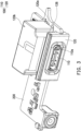
- FIG. 3 is a schematic view of the waterproof connector of FIG. 1 from another perspective.
- FIG. 4 is a schematic view of the waterproof covering member in FIG. 3 becoming transparent.
- a waterproof connector 100 is disposed on a circuit board 200.
- the waterproof connector 100 includes a connector 110 and a waterproof covering member 120.
- the connector 110 is disposed on the circuit board 200 and electrically connected to the circuit board 200, and the waterproof covering member 120 covers the connector 110 and a part of the circuit board 200.
- a material of the waterproof covering member 120 in this embodiment is rubber, but it is not limited thereto. Those skilled in the art may select other materials that may also achieve a waterproof effect according to requirements.
- FIG. 5 is a cross-sectional view of FIG. 1 .
- the connector 110 has an insertion interface 110a
- the waterproof covering member 120 covers an upper side, a lower side, a left side, a right side, and a rear side of the connector 110, and exposes the insertion interface 110a.
- the waterproof covering member 120 may have an opening 122 with a shape of "U".
- the connector 110 is disposed in the opening 122 with the shape of "U", and then a part of the waterproof covering member 120 that exceeds the connector 110 is attached to the circuit board 200 by an adhesive.
- an inner surface 120a of the waterproof covering member 120 configured to contact the circuit board 200 has an adhesive overflow groove 124. Therefore, excess residual adhesive flows into the adhesive overflow groove 124 to be collected.
- the waterproof covering member120 covers the connector 110 and the part of the circuit board 200. That is, the circuit board 200 is provided with the connector 110 and a part around the connector 110. Therefore, a shape and size of the waterproof covering member 120 may be adjusted according to the requirements, so that the waterproof covering member 120 may further provide waterproof protection for a circuit near the connector 110 on the circuit board 200.
- FIG. 6 is a partial cross-sectional view of an electronic device.
- the circuit board 200 is disposed in an electronic device 500.
- the electronic device 500 may be a desktop computer host, a notebook computer host, a USB flash drive, or other suitable electronic devices.
- the electronic device 500 includes a housing 300, and the waterproof covering member 120 is inserted with the housing 300.
- an outer surface 120b of the waterproof covering member 120 configured to contact the housing 300 further has a rib 126, so as to further prevent water vapor from entering the housing 300.
- the rib 126 may be disposed on at least any one of the outer surfaces 120b of a top, bottom, left, right, front and rear of the waterproof covering member 120.
- the number of the ribs 126 disposed on each of the outer surfaces 120b is not limited, and the number of the ribs 126 may be adjusted according to the actual requirements.
- the rib 126 of the waterproof covering member 120 facing the housing abuts against the housing 300, and the rib 126 of the waterproof covering member 120 facing other mechanical members 400 disposed in the housing 300 abuts against the mechanical member 400.
- the water vapor may be prevented from entering an inside of the electronic device 500, and the electronic device 500 has the good waterproof effect.
- the waterproof covering member covers the connector and the part of the circuit board at the same time, and abuts against the housing and the mechanical member disposed in the housing by the rib, so as to provide the good waterproof effect for both the connector and the circuit board. Therefore, such disposing method may be also suitable for a connector that does not originally have waterproof specifications.
- the waterproof covering member not only covers an adjacent periphery where the circuit board is provided with the connector, but also extends a length of the waterproof covering member covering the circuit board according to the requirements, so as to expand a range of the waterproof cover member covering the circuit board, and further provide the waterproof protection for the circuit near the connector on the circuit board.
Landscapes
- Connector Housings Or Holding Contact Members (AREA)
Description
- The disclosure relates to an electronic device including a connector, and more particularly, a waterproof connector.
- In order to expand the application of electronic devices and peripheral accessories, connectors are common application components in electronic devices.
- In the conventional practice, a o-ring with soft material is sandwiched between the connector of the electronic device and the housing to provide waterproofing.
- However, it is often the case that the o-ring interferes with the housing or other internal components during assembly, resulting in not being assembled in the expected position and causing water leakage.
US 10 797 429 B2
WO 2019/092749 A1 discloses a water resistant electrical connector assembly for a vehicle, having a PCB, a connector receptacle mounted on a PCB, a plurality of electronic components mounted on the PCB, a housing supporting the PCB in the housing, the housing defining a cavity having a fore end configured for positioning of the connector receptacle and allowing access to the connector receptacle from outside the housing; and a sealing means positioned in the housing, the sealing means adapted to isolate the fore end from the back end. - The disclosure provides a waterproof connector with a waterproof effect.
- The invention is defined by the technical features of independent claim 1.
- In an embodiment of the disclosure, a material of the waterproof covering member is rubber.
- In an embodiment of the disclosure, an inner surface of the waterproof covering member contacting the circuit board has an adhesive overflow groove.
- In an embodiment of the disclosure, the ribs are disposed on at least one of the outer surfaces of the waterproof covering member.
- In an embodiment of the disclosure, the ribs are disposed on the outer surface of the waterproof covering member facing the housing, and abut against the housing.
- In an embodiment of the disclosure, the ribs are disposed on the outer surface of the waterproof covering member facing a mechanical member of the electronic device, and abut against the mechanical member.
- Based on the above, in the waterproof connector of the disclosure, the waterproof covering member covers the connector and a part of the circuit board at the same time, so as to provide the good waterproof effect for the inside of the electronic device. Therefore, such disposing method is also suitable for a connector that does not have waterproof specifications
-
-
FIG. 1 is a schematic view of a waterproof connector according to the disclosure. -
FIG. 2 is a schematic view of a waterproof covering member inFIG. 1 becoming transparent. -
FIG. 3 is a schematic view of the waterproof connector ofFIG. 1 from another perspective. -
FIG. 4 is a schematic view of the waterproof covering member inFIG. 3 becoming transparent. -
FIG. 5 is a cross-sectional view ofFIG. 1 . -
FIG. 6 is a partial cross-sectional view of an electronic device. -
FIG. 1 is a schematic view of a waterproof connector according to the disclosure.FIG. 2 is a schematic view of a waterproof covering member inFIG. 1 becoming transparent.FIG. 3 is a schematic view of the waterproof connector ofFIG. 1 from another perspective.FIG. 4 is a schematic view of the waterproof covering member inFIG. 3 becoming transparent. Referring toFIGs. 1 to 4 together, awaterproof connector 100 is disposed on acircuit board 200. Thewaterproof connector 100 includes aconnector 110 and a waterproof coveringmember 120. Theconnector 110 is disposed on thecircuit board 200 and electrically connected to thecircuit board 200, and thewaterproof covering member 120 covers theconnector 110 and a part of thecircuit board 200. - A material of the waterproof covering
member 120 in this embodiment is rubber, but it is not limited thereto. Those skilled in the art may select other materials that may also achieve a waterproof effect according to requirements. -
FIG. 5 is a cross-sectional view ofFIG. 1 . Referring toFIGs. 2 ,4 , and5 together, specifically, theconnector 110 has aninsertion interface 110a, and the waterproof coveringmember 120 covers an upper side, a lower side, a left side, a right side, and a rear side of theconnector 110, and exposes theinsertion interface 110a. - In addition, the waterproof covering
member 120 may have anopening 122 with a shape of "U". Theconnector 110 is disposed in theopening 122 with the shape of "U", and then a part of the waterproof coveringmember 120 that exceeds theconnector 110 is attached to thecircuit board 200 by an adhesive. In order to prevent the adhesive from overflowing outside the waterproof coveringmember 120 and affecting other components on thecircuit board 200, aninner surface 120a of the waterproof coveringmember 120 configured to contact thecircuit board 200 has anadhesive overflow groove 124. Therefore, excess residual adhesive flows into theadhesive overflow groove 124 to be collected. - In light of the above, the waterproof covering member120 covers the
connector 110 and the part of thecircuit board 200. That is, thecircuit board 200 is provided with theconnector 110 and a part around theconnector 110. Therefore, a shape and size of the waterproof coveringmember 120 may be adjusted according to the requirements, so that the waterproof coveringmember 120 may further provide waterproof protection for a circuit near theconnector 110 on thecircuit board 200. -
FIG. 6 is a partial cross-sectional view of an electronic device. Referring toFIGs. 1 ,3 , and6 together, thecircuit board 200 is disposed in anelectronic device 500. Theelectronic device 500 may be a desktop computer host, a notebook computer host, a USB flash drive, or other suitable electronic devices. Theelectronic device 500 includes ahousing 300, and the waterproof coveringmember 120 is inserted with thehousing 300. In order to enhance the waterproof effect, anouter surface 120b of the waterproof coveringmember 120 configured to contact thehousing 300 further has arib 126, so as to further prevent water vapor from entering thehousing 300. Therib 126 may be disposed on at least any one of theouter surfaces 120b of a top, bottom, left, right, front and rear of the waterproof coveringmember 120. The number of theribs 126 disposed on each of theouter surfaces 120b is not limited, and the number of theribs 126 may be adjusted according to the actual requirements. Therib 126 of the waterproof coveringmember 120 facing the housing abuts against thehousing 300, and therib 126 of the waterproof coveringmember 120 facing othermechanical members 400 disposed in thehousing 300 abuts against themechanical member 400. By therib 126 abutting against thehousing 300 and themechanical member 400, the water vapor may be prevented from entering an inside of theelectronic device 500, and theelectronic device 500 has the good waterproof effect. - Based on the above, in the waterproof connector of the disclosure, the waterproof covering member covers the connector and the part of the circuit board at the same time, and abuts against the housing and the mechanical member disposed in the housing by the rib, so as to provide the good waterproof effect for both the connector and the circuit board. Therefore, such disposing method may be also suitable for a connector that does not originally have waterproof specifications.
- In addition, the waterproof covering member not only covers an adjacent periphery where the circuit board is provided with the connector, but also extends a length of the waterproof covering member covering the circuit board according to the requirements, so as to expand a range of the waterproof cover member covering the circuit board, and further provide the waterproof protection for the circuit near the connector on the circuit board.
Claims (6)
- An electronic device (500) comprising a waterproof connector (100), a circuit board (200) and a housing (300), wherein the waterproof connector (100) is disposed on the circuit board (200) and inserted with the housing (300), the waterproof connector (100) comprising:a connector (110) disposed on the circuit board (200); anda waterproof covering member (120) covering the connector (110) and a part of the circuit board (200), wherein an outer surface (120b) of the waterproof covering member (120) has a plurality of ribs (126), and the plurality of ribs (126) contact the housing (300) to provide waterproof protection for an inside of the electronic device (500); the electronic device being characterized in thatan inner surface (120a) of a part of the waterproof covering member (120) that exceeds the connector (110) is attached to the circuit board (200) by an adhesive, andin that the inner surface (120a) of the part of the waterproof covering member (120) that exceeds the connector (110) has an adhesive overflow groove (124).
- The electronic device (500) according to claim 1, wherein the connector (110) has an insertion interface (110a), and the waterproof covering member (120) exposes the insertion interface (110a).
- The electronic device (500) according to claim 1, wherein a material of the waterproof covering member (120) is rubber.
- The electronic device (500) according to claim 1, wherein the plurality of ribs are disposed on at least one of the outer surfaces (120b) of the waterproof covering member (120).
- The electronic device (500) according to claim 4, wherein the plurality of ribs are disposed on the outer surface (120b) of the waterproof covering member (120) facing the housing (300), and abut against the housing (300).
- The electronic device (500) according to claim 4, wherein the plurality of ribs are disposed on the outer surface (120b) of the waterproof covering member (120) facing a mechanical member (400) of the electronic device (500), and abut against the mechanical member (400).
Applications Claiming Priority (1)
| Application Number | Priority Date | Filing Date | Title |
|---|---|---|---|
| TW110200140U TWM610095U (en) | 2021-01-06 | 2021-01-06 | Waterproof connector |
Publications (3)
| Publication Number | Publication Date |
|---|---|
| EP4027466A1 EP4027466A1 (en) | 2022-07-13 |
| EP4027466C0 EP4027466C0 (en) | 2024-10-16 |
| EP4027466B1 true EP4027466B1 (en) | 2024-10-16 |
Family
ID=76605702
Family Applications (1)
| Application Number | Title | Priority Date | Filing Date |
|---|---|---|---|
| EP21203323.7A Active EP4027466B1 (en) | 2021-01-06 | 2021-10-19 | Waterproof connector |
Country Status (3)
| Country | Link |
|---|---|
| US (1) | US11522313B2 (en) |
| EP (1) | EP4027466B1 (en) |
| TW (1) | TWM610095U (en) |
Family Cites Families (8)
| Publication number | Priority date | Publication date | Assignee | Title |
|---|---|---|---|---|
| US6244886B1 (en) * | 2000-01-24 | 2001-06-12 | Delphi Technologies, Inc. | Electrical connection system having force distribution seal |
| TWI578636B (en) | 2015-03-11 | 2017-04-11 | 鴻騰精密科技股份有限公司 | Electrical connector and method of making the same |
| TWI566481B (en) | 2016-07-13 | 2017-01-11 | 矽瑪科技股份有限公司 | The use of waterproof colloid fixed connection terminals and circuit board signal connector |
| CN107681316A (en) | 2017-09-19 | 2018-02-09 | 赛尔康技术(深圳)有限公司 | A kind of waterproof A type USB connector female seats and its manufacture method |
| WO2019092749A1 (en) | 2017-11-13 | 2019-05-16 | Minda Industries Limited | Electrical connector assembly |
| US10989394B2 (en) * | 2018-01-09 | 2021-04-27 | OLEDWorks LLC | Thin OLED lighting module |
| TWI697266B (en) | 2018-05-07 | 2020-06-21 | 和碩聯合科技股份有限公司 | Electronic device |
| WO2019244511A1 (en) | 2018-06-19 | 2019-12-26 | 株式会社オートネットワーク技術研究所 | Electrical connection box |
-
2021
- 2021-01-06 TW TW110200140U patent/TWM610095U/en unknown
- 2021-09-16 US US17/477,242 patent/US11522313B2/en active Active
- 2021-10-19 EP EP21203323.7A patent/EP4027466B1/en active Active
Also Published As
| Publication number | Publication date |
|---|---|
| EP4027466A1 (en) | 2022-07-13 |
| EP4027466C0 (en) | 2024-10-16 |
| US11522313B2 (en) | 2022-12-06 |
| TWM610095U (en) | 2021-04-01 |
| US20220216644A1 (en) | 2022-07-07 |
Similar Documents
| Publication | Publication Date | Title |
|---|---|---|
| JP5736137B2 (en) | Flat cable connector | |
| US20210059065A1 (en) | Electronic device and cable organizing assembly | |
| US9893459B2 (en) | Electrical connector having a tongue portion extending beyond a metallic shell | |
| JP6452529B2 (en) | connector | |
| KR101301982B1 (en) | Waterproof type receptacle connector | |
| US20170162975A1 (en) | Electrical connector | |
| KR20130122669A (en) | Connector of electronic device, plug of electronic device, and waterproof structure of electronic device | |
| US20060189183A1 (en) | Camera module connector | |
| US7484981B2 (en) | Assembly for sealing an audio connector within an electronic device | |
| TWI849047B (en) | Ruggedized electrical receptacle | |
| US9373907B2 (en) | Flexible flat cable, electrical connector, and flexible flat cable assembly | |
| CN115473072A (en) | Connector and electronic device | |
| KR102740378B1 (en) | Receptacle connector | |
| US9288925B2 (en) | Electrical connector and electronic device having the same | |
| EP2345949A2 (en) | A waterproof casing with multiple isolated compartments | |
| JP4916388B2 (en) | Portable electronic devices | |
| EP4027466A1 (en) | Waterproof connector | |
| CN112821129B (en) | Backplane Connector Assemblies and Seal Assemblies for Backplane Connectors | |
| KR102319021B1 (en) | Receptacle connector | |
| EP4175279B1 (en) | Camera module | |
| US6053772A (en) | Narrow pitch multiple board connector assembly and shield shell connecting fitting used for the same | |
| KR102397522B1 (en) | Connector assembly | |
| KR102652498B1 (en) | Waterproof connector assembly and electronic device including the same | |
| TWI431860B (en) | Connector waterproof structure and portable electronic device using the same | |
| KR200449950Y1 (en) | Prefabricated A pluggable USB memory device |
Legal Events
| Date | Code | Title | Description |
|---|---|---|---|
| PUAI | Public reference made under article 153(3) epc to a published international application that has entered the european phase |
Free format text: ORIGINAL CODE: 0009012 |
|
| STAA | Information on the status of an ep patent application or granted ep patent |
Free format text: STATUS: THE APPLICATION HAS BEEN PUBLISHED |
|
| AK | Designated contracting states |
Kind code of ref document: A1 Designated state(s): AL AT BE BG CH CY CZ DE DK EE ES FI FR GB GR HR HU IE IS IT LI LT LU LV MC MK MT NL NO PL PT RO RS SE SI SK SM TR |
|
| STAA | Information on the status of an ep patent application or granted ep patent |
Free format text: STATUS: REQUEST FOR EXAMINATION WAS MADE |
|
| 17P | Request for examination filed |
Effective date: 20221130 |
|
| RBV | Designated contracting states (corrected) |
Designated state(s): AL AT BE BG CH CY CZ DE DK EE ES FI FR GB GR HR HU IE IS IT LI LT LU LV MC MK MT NL NO PL PT RO RS SE SI SK SM TR |
|
| GRAP | Despatch of communication of intention to grant a patent |
Free format text: ORIGINAL CODE: EPIDOSNIGR1 |
|
| STAA | Information on the status of an ep patent application or granted ep patent |
Free format text: STATUS: GRANT OF PATENT IS INTENDED |
|
| INTG | Intention to grant announced |
Effective date: 20240515 |
|
| GRAS | Grant fee paid |
Free format text: ORIGINAL CODE: EPIDOSNIGR3 |
|
| GRAA | (expected) grant |
Free format text: ORIGINAL CODE: 0009210 |
|
| STAA | Information on the status of an ep patent application or granted ep patent |
Free format text: STATUS: THE PATENT HAS BEEN GRANTED |
|
| AK | Designated contracting states |
Kind code of ref document: B1 Designated state(s): AL AT BE BG CH CY CZ DE DK EE ES FI FR GB GR HR HU IE IS IT LI LT LU LV MC MK MT NL NO PL PT RO RS SE SI SK SM TR |
|
| REG | Reference to a national code |
Ref country code: GB Ref legal event code: FG4D |
|
| REG | Reference to a national code |
Ref country code: CH Ref legal event code: EP Ref country code: DE Ref legal event code: R096 Ref document number: 602021020276 Country of ref document: DE |
|
| REG | Reference to a national code |
Ref country code: IE Ref legal event code: FG4D |
|
| U01 | Request for unitary effect filed |
Effective date: 20241016 |
|
| U07 | Unitary effect registered |
Designated state(s): AT BE BG DE DK EE FI FR IT LT LU LV MT NL PT RO SE SI Effective date: 20241028 |
|
| U20 | Renewal fee for the european patent with unitary effect paid |
Year of fee payment: 4 Effective date: 20241029 |
|
| PG25 | Lapsed in a contracting state [announced via postgrant information from national office to epo] |
Ref country code: IS Free format text: LAPSE BECAUSE OF FAILURE TO SUBMIT A TRANSLATION OF THE DESCRIPTION OR TO PAY THE FEE WITHIN THE PRESCRIBED TIME-LIMIT Effective date: 20250216 Ref country code: HR Free format text: LAPSE BECAUSE OF FAILURE TO SUBMIT A TRANSLATION OF THE DESCRIPTION OR TO PAY THE FEE WITHIN THE PRESCRIBED TIME-LIMIT Effective date: 20241016 |
|
| PG25 | Lapsed in a contracting state [announced via postgrant information from national office to epo] |
Ref country code: ES Free format text: LAPSE BECAUSE OF FAILURE TO SUBMIT A TRANSLATION OF THE DESCRIPTION OR TO PAY THE FEE WITHIN THE PRESCRIBED TIME-LIMIT Effective date: 20241016 |
|
| PG25 | Lapsed in a contracting state [announced via postgrant information from national office to epo] |
Ref country code: NO Free format text: LAPSE BECAUSE OF FAILURE TO SUBMIT A TRANSLATION OF THE DESCRIPTION OR TO PAY THE FEE WITHIN THE PRESCRIBED TIME-LIMIT Effective date: 20250116 |
|
| PG25 | Lapsed in a contracting state [announced via postgrant information from national office to epo] |
Ref country code: GR Free format text: LAPSE BECAUSE OF FAILURE TO SUBMIT A TRANSLATION OF THE DESCRIPTION OR TO PAY THE FEE WITHIN THE PRESCRIBED TIME-LIMIT Effective date: 20250117 |
|
| PG25 | Lapsed in a contracting state [announced via postgrant information from national office to epo] |
Ref country code: PL Free format text: LAPSE BECAUSE OF FAILURE TO SUBMIT A TRANSLATION OF THE DESCRIPTION OR TO PAY THE FEE WITHIN THE PRESCRIBED TIME-LIMIT Effective date: 20241016 |
|
| PG25 | Lapsed in a contracting state [announced via postgrant information from national office to epo] |
Ref country code: RS Free format text: LAPSE BECAUSE OF FAILURE TO SUBMIT A TRANSLATION OF THE DESCRIPTION OR TO PAY THE FEE WITHIN THE PRESCRIBED TIME-LIMIT Effective date: 20250116 |
|
| REG | Reference to a national code |
Ref country code: CH Ref legal event code: PL |
|
| PG25 | Lapsed in a contracting state [announced via postgrant information from national office to epo] |
Ref country code: SM Free format text: LAPSE BECAUSE OF FAILURE TO SUBMIT A TRANSLATION OF THE DESCRIPTION OR TO PAY THE FEE WITHIN THE PRESCRIBED TIME-LIMIT Effective date: 20241016 |
|
| PG25 | Lapsed in a contracting state [announced via postgrant information from national office to epo] |
Ref country code: MC Free format text: LAPSE BECAUSE OF FAILURE TO SUBMIT A TRANSLATION OF THE DESCRIPTION OR TO PAY THE FEE WITHIN THE PRESCRIBED TIME-LIMIT Effective date: 20241016 |
|
| PG25 | Lapsed in a contracting state [announced via postgrant information from national office to epo] |
Ref country code: CH Free format text: LAPSE BECAUSE OF NON-PAYMENT OF DUE FEES Effective date: 20241031 |
|
| PG25 | Lapsed in a contracting state [announced via postgrant information from national office to epo] |
Ref country code: SK Free format text: LAPSE BECAUSE OF FAILURE TO SUBMIT A TRANSLATION OF THE DESCRIPTION OR TO PAY THE FEE WITHIN THE PRESCRIBED TIME-LIMIT Effective date: 20241016 |
|
| PG25 | Lapsed in a contracting state [announced via postgrant information from national office to epo] |
Ref country code: CZ Free format text: LAPSE BECAUSE OF FAILURE TO SUBMIT A TRANSLATION OF THE DESCRIPTION OR TO PAY THE FEE WITHIN THE PRESCRIBED TIME-LIMIT Effective date: 20241016 |
|
| PLBE | No opposition filed within time limit |
Free format text: ORIGINAL CODE: 0009261 |
|
| STAA | Information on the status of an ep patent application or granted ep patent |
Free format text: STATUS: NO OPPOSITION FILED WITHIN TIME LIMIT |
|
| U20 | Renewal fee for the european patent with unitary effect paid |
Year of fee payment: 5 Effective date: 20250811 |
|
| 26N | No opposition filed |
Effective date: 20250717 |
|
| PG25 | Lapsed in a contracting state [announced via postgrant information from national office to epo] |
Ref country code: IE Free format text: LAPSE BECAUSE OF NON-PAYMENT OF DUE FEES Effective date: 20241019 |
|
| PG25 | Lapsed in a contracting state [announced via postgrant information from national office to epo] |
Ref country code: CY Free format text: LAPSE BECAUSE OF FAILURE TO SUBMIT A TRANSLATION OF THE DESCRIPTION OR TO PAY THE FEE WITHIN THE PRESCRIBED TIME-LIMIT; INVALID AB INITIO Effective date: 20211019 |
|
| PG25 | Lapsed in a contracting state [announced via postgrant information from national office to epo] |
Ref country code: HU Free format text: LAPSE BECAUSE OF FAILURE TO SUBMIT A TRANSLATION OF THE DESCRIPTION OR TO PAY THE FEE WITHIN THE PRESCRIBED TIME-LIMIT; INVALID AB INITIO Effective date: 20211019 |