EP4027442A1 - Battery module, battery pack comprising same battery module, and vehicle - Google Patents
Battery module, battery pack comprising same battery module, and vehicle Download PDFInfo
- Publication number
- EP4027442A1 EP4027442A1 EP21803176.3A EP21803176A EP4027442A1 EP 4027442 A1 EP4027442 A1 EP 4027442A1 EP 21803176 A EP21803176 A EP 21803176A EP 4027442 A1 EP4027442 A1 EP 4027442A1
- Authority
- EP
- European Patent Office
- Prior art keywords
- frame
- battery module
- battery
- present disclosure
- cell assembly
- Prior art date
- Legal status (The legal status is an assumption and is not a legal conclusion. Google has not performed a legal analysis and makes no representation as to the accuracy of the status listed.)
- Granted
Links
Images





Classifications
-
- H—ELECTRICITY
- H01—ELECTRIC ELEMENTS
- H01M—PROCESSES OR MEANS, e.g. BATTERIES, FOR THE DIRECT CONVERSION OF CHEMICAL ENERGY INTO ELECTRICAL ENERGY
- H01M50/00—Constructional details or processes of manufacture of the non-active parts of electrochemical cells other than fuel cells, e.g. hybrid cells
- H01M50/20—Mountings; Secondary casings or frames; Racks, modules or packs; Suspension devices; Shock absorbers; Transport or carrying devices; Holders
- H01M50/204—Racks, modules or packs for multiple batteries or multiple cells
-
- H—ELECTRICITY
- H01—ELECTRIC ELEMENTS
- H01M—PROCESSES OR MEANS, e.g. BATTERIES, FOR THE DIRECT CONVERSION OF CHEMICAL ENERGY INTO ELECTRICAL ENERGY
- H01M50/00—Constructional details or processes of manufacture of the non-active parts of electrochemical cells other than fuel cells, e.g. hybrid cells
- H01M50/20—Mountings; Secondary casings or frames; Racks, modules or packs; Suspension devices; Shock absorbers; Transport or carrying devices; Holders
-
- H—ELECTRICITY
- H01—ELECTRIC ELEMENTS
- H01M—PROCESSES OR MEANS, e.g. BATTERIES, FOR THE DIRECT CONVERSION OF CHEMICAL ENERGY INTO ELECTRICAL ENERGY
- H01M50/00—Constructional details or processes of manufacture of the non-active parts of electrochemical cells other than fuel cells, e.g. hybrid cells
- H01M50/20—Mountings; Secondary casings or frames; Racks, modules or packs; Suspension devices; Shock absorbers; Transport or carrying devices; Holders
- H01M50/204—Racks, modules or packs for multiple batteries or multiple cells
- H01M50/207—Racks, modules or packs for multiple batteries or multiple cells characterised by their shape
- H01M50/211—Racks, modules or packs for multiple batteries or multiple cells characterised by their shape adapted for pouch cells
-
- H—ELECTRICITY
- H01—ELECTRIC ELEMENTS
- H01M—PROCESSES OR MEANS, e.g. BATTERIES, FOR THE DIRECT CONVERSION OF CHEMICAL ENERGY INTO ELECTRICAL ENERGY
- H01M10/00—Secondary cells; Manufacture thereof
- H01M10/60—Heating or cooling; Temperature control
- H01M10/62—Heating or cooling; Temperature control specially adapted for specific applications
- H01M10/625—Vehicles
-
- H—ELECTRICITY
- H01—ELECTRIC ELEMENTS
- H01M—PROCESSES OR MEANS, e.g. BATTERIES, FOR THE DIRECT CONVERSION OF CHEMICAL ENERGY INTO ELECTRICAL ENERGY
- H01M50/00—Constructional details or processes of manufacture of the non-active parts of electrochemical cells other than fuel cells, e.g. hybrid cells
- H01M50/20—Mountings; Secondary casings or frames; Racks, modules or packs; Suspension devices; Shock absorbers; Transport or carrying devices; Holders
- H01M50/267—Mountings; Secondary casings or frames; Racks, modules or packs; Suspension devices; Shock absorbers; Transport or carrying devices; Holders having means for adapting to batteries or cells of different types or different sizes
-
- H—ELECTRICITY
- H01—ELECTRIC ELEMENTS
- H01M—PROCESSES OR MEANS, e.g. BATTERIES, FOR THE DIRECT CONVERSION OF CHEMICAL ENERGY INTO ELECTRICAL ENERGY
- H01M2220/00—Batteries for particular applications
- H01M2220/20—Batteries in motive systems, e.g. vehicle, ship, plane
-
- Y—GENERAL TAGGING OF NEW TECHNOLOGICAL DEVELOPMENTS; GENERAL TAGGING OF CROSS-SECTIONAL TECHNOLOGIES SPANNING OVER SEVERAL SECTIONS OF THE IPC; TECHNICAL SUBJECTS COVERED BY FORMER USPC CROSS-REFERENCE ART COLLECTIONS [XRACs] AND DIGESTS
- Y02—TECHNOLOGIES OR APPLICATIONS FOR MITIGATION OR ADAPTATION AGAINST CLIMATE CHANGE
- Y02E—REDUCTION OF GREENHOUSE GAS [GHG] EMISSIONS, RELATED TO ENERGY GENERATION, TRANSMISSION OR DISTRIBUTION
- Y02E60/00—Enabling technologies; Technologies with a potential or indirect contribution to GHG emissions mitigation
- Y02E60/10—Energy storage using batteries
Definitions
- the present disclosure relates to a battery module, a battery pack comprising the battery module and a vehicle, and more particularly, to a battery module with reduced manufacturing cost and a battery pack comprising the same.
- a lithium secondary battery primarily uses a lithium-based oxide and a carbon material for a positive electrode active material and a negative electrode active material respectively. Additionally, the lithium secondary battery includes an electrode assembly including a positive electrode plate and a negative electrode plate respectively coated with the positive electrode active material and the negative electrode active material and a separator interposed between the positive electrode plate and the negative electrode plate, and a cylindrical battery case or a packaging in which the electrode assembly is received together with an electrolyte solution in an airtight manner.
- secondary batteries are being widely used in not only small devices such as portable electronic products but also medium- and large-scale devices such as vehicles and energy storage systems (ESSs).
- ESSs vehicles and energy storage systems
- many secondary batteries are electrically connected to increase the capacity and output.
- pouch-type secondary batteries are widely used in medium- and large-scale devices due to their advantage that they can be easily stacked.
- a battery pack including a plurality of battery modules, each battery module including a plurality of secondary batteries connected in series and/or in parallel.
- secondary batteries of various sizes may be applied according to the capacity of the battery module required for products. That is, the size change of the secondary batteries leads to a size change of a module housing in which the plurality of secondary batteries is received, which requires a design modification of the module housing and a change in production equipment. The design modification greatly increases the manufacturing cost of the battery module or the battery pack, and is a factor that impedes the production cost reduction.
- the present disclosure is designed to solve the above-described problem, and therefore the present disclosure is directed to providing a battery module with reduced manufacturing cost, a battery pack comprising the same and a vehicle.
- a battery module includes a cell assembly including a plurality of secondary batteries, and a module housing in which the cell assembly is received, wherein the module housing includes at least two frames capable of changing a length of the module housing according to a size of the cell assembly.
- the at least two frames may be configured such that one frame is received in an internal space of the other frame or one frame extends from the internal space of the other frame.
- each of the at least two frames may include a cover plate which covers a top of the cell assembly and sides of the cell assembly in a horizontal direction, and a bottom plate coupled with a bottom of the cover plate and configured to mount the cell assembly.
- each of the at least two frames may have a coupling groove into which a part of other frame is inserted, and an insertion portion which is inserted into the coupling groove of the other frame.
- each of the coupling groove and the insertion portion may extend in a lengthwise direction in which the module housing changes, and the at least two frames may be configured to be movable in the lengthwise direction when the coupling groove and the insertion portion are coupled to each other.
- any one of the at least two frames may be configured to receive at least one other frame therein by the coupling of the coupling groove and the insertion portion.
- cover plate and the bottom plate may include an insertion groove running inward to couple the cover plate and the bottom plate, and a coupling protrusion to be configured to be inserted into the insertion groove.
- the battery module may further include a fixing member configured to limit the length change of the module housing.
- the battery module may further include a filler configured to fill an empty space of the coupling groove into which the insertion portion is not inserted.
- a battery pack of the present disclosure includes at least two battery modules wherein the at least two battery modules are arranged such that sides of the module housings come into contact with each other.
- any one of the at least two frames of the battery module may have a larger size than the other frame to receive the other frame therein, and the frame having the larger size in the one battery module and the frame having a smaller size in the other battery module may be arranged in contact with each other.
- a vehicle according to the present disclosure includes the battery pack according to the present disclosure.
- the battery module of the present disclosure includes the module housing including the at least two frames capable of changing the length of the module housing according to the size of the cell assembly, thereby adjusting the length of the module housing according to the size of the cell assembly, so one type of module housing may be applied to the battery modules of various sizes, thereby eliminating the need to produce the module housings of different sizes for each of the battery modules of various sizes. Accordingly, the battery module of the present disclosure is easy to customize, which makes mass production easy and eliminates the need to change the design of products, thereby dramatically reducing the manufacturing cost.
- the at least two frames of the present disclosure may be configured such that any one frame accommodates at least one other frame by coupling of the coupling groove and the insertion portion, thereby reducing the module housing according to the size of the cell assembly applied.
- the battery module of the present disclosure may be manufactured by minimizing the size of the module housing to deliver in a compact size and making primary or secondary modification according to the size of the cell assembly in the assembling process. Accordingly, it is possible to reduce the delivery or storage cost of the battery module.
- the battery pack of the present disclosure is configured such that the frame having a larger size in one battery module and the frame having a smaller size in the other battery module are arranged in contact with each other, thereby minimizing the size of the gap between the plurality of battery modules, and effectively increasing the energy density of the battery pack. Additionally, when the plurality of battery modules is arranged in contact with each other, there is no empty space, so the battery modules may not lose the arrangement from external impacts. Accordingly, it is possible to effectively increase the durability of the battery pack.
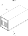
- FIG. 1 is a perspective view schematically showing a battery module according to an embodiment of the present disclosure. Additionally, FIG. 2 is an exploded perspective view schematically showing the battery module according to an embodiment of the present disclosure.
- X axis direction is the left direction
- Y axis direction is the rear direction
- Z axis direction is the up direction.
- the battery module 200 of the present disclosure includes a cell assembly 100 and a module housing 210.
- the cell assembly 100 may include a plurality of secondary batteries 110.
- the secondary battery 110 may be a pouch-type secondary battery 110.
- the pouch-type secondary battery 110 may include an electrode assembly, an electrolyte and a pouch case.
- the electrode assembly may include at least one positive electrode plate and at least negative electrode plate with a separator interposed between. More specifically, the electrode assembly may be classified into a winding type electrode assembly in which a positive electrode plate and a negative electrode plate are wound together with a separator, and a stack type electrode assembly in which a plurality of positive electrode plates and a plurality of negative electrode plate are stacked in an alternating manner with a separator interposed between.
- the pouch case may include an outer insulating layer, a metal layer and an inner insulating layer.
- the pouch case may include a metal thin film, for example, an aluminum thin film, to protect the internal components such as the electrode assembly and the electrolyte solution, and enhance the electrical and chemical properties by the electrode assembly and the electrolyte solution and heat radiation.
- the aluminum thin film may be interposed between the insulating layers to ensure electrical insulation from the internal components of the secondary batteries 110 such as the electrode assembly and the electrolyte solution or other components outside of the secondary batteries 110.
- the pouch case may include 2 pouches, and at least one of the pouches may have a concave internal space.
- the electrode assembly may be received in the internal space of the pouch.
- a sealing portion may be provided on the outer peripheral surfaces of the 2 pouches, and when joined together, the sealing portions may hermetically seal the internal space in which the electrode assembly is received.
- Each pouch-type secondary battery 110 may include an electrode lead 111, and the electrode lead 111 may include a positive electrode lead and a negative electrode lead.
- the electrode lead 111 may extend frontward or rearward from the sealing portion disposed at the front or rear outer periphery of the pouch case. Additionally, the electrode lead 111 may serve as an electrode terminal of the secondary battery 110. For example, as shown in FIG. 2 , one electrode lead 111 may extend frontward from the secondary battery 110, and the other electrode lead 111 may extend rearward from the secondary battery 110.
- the battery module 200 may include the plurality of pouch-type secondary batteries 110 stacked and arranged in at least one direction.
- the plurality of pouch-type secondary batteries 110 may be horizontally stacked side by side.
- each pouch-type secondary battery 110 may stand in a direction approximately perpendicular to the ground with the two wide surfaces disposed on the left and right sides respectively and the sealing portions disposed in the up, down, front and rear directions, when viewed from the front side.
- each secondary battery 110 may stand vertically.
- the configuration of the pouch-type secondary batteries 110 is obvious to those skilled in the art, and its detailed description is omitted herein. Additionally, the cell assembly 100 according to the present disclosure may employ various types of secondary batteries well known at the time of filing the patent application.
- the battery module 200 of the present disclosure may include the busbar electrically connecting the plurality of secondary batteries 110 of the cell assembly 100.
- the busbar may be mounted on a busbar frame of the busbar assembly.
- the busbar may include a metal material.
- the busbar may be disposed on each of the front and rear sides of the cell assembly 100.
- the module housing 210 may serve as a case in the battery module 200. Accordingly, the module housing 210 serves to provide structural stability to the battery module 200, and protect the components received therein such as the cell assembly 100 from external mechanical elements such as impacts or materials. To this end, the module housing 210 may include metals such as steel or aluminum or nonconductive plastics.
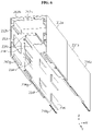
- FIG. 3 is a perspective view schematically showing primary modification of the battery module of FIG. 1 of the present disclosure. Additionally, FIG. 4 is a perspective view schematically showing secondary modification of the battery module of FIG. 1 of the present disclosure.
- the module housing 210 may include at least two frames 212, 214, 216.
- the at least two frames 212, 214, 216 may be configured to change the length of the module housing 210 according to the size of the cell assembly 100. For example, when the length in the front-rear direction of the cell assembly 100 received in the battery module 200 shown in FIG. 3 is longer than the length of the cell assembly 100 shown in FIG. 2 , the battery module 200 may have primary modification so that the length of the module housing 210 in the front-rear direction increases about twice. Additionally, the module housing 210 of the battery module 200 shown in FIG. 4 may have secondary modification so that the length in the front-rear direction (Y axis direction) increases about 3 times on the basis of the length of the module housing 210 shown in FIG. 1 .
- the module housing 210 includes the at least two frames 212, 214, 216 capable of changing the length of the module housing 210 according to the size of the cell assembly 100, thereby adjusting the length of the module housing 210 according to the size of the cell assembly 100, so one type of module housing 210 may be applied to the battery modules 200 of various sizes, thereby eliminating the need to produce the module housings 210 of different sizes for each of the battery modules 200 of various sizes. Accordingly, the battery module 200 of the present disclosure is easy to customize, which makes mass production easy and eliminates the need to change the design of products, thereby dramatically reducing the manufacturing cost.
- the at least two frames 212, 214, 216 may have an internal space for receiving the cell assembly 100.
- the at least two frames 212, 214, 216 may have an upper wall, a left side wall, a right side wall and a lower wall to form a cuboidal internal space.
- the at least two frames 212, 214, 216 may be open in the front-rear direction so that the cell assembly 100 may be inserted in the front-rear direction.
- the at least two frames 212, 214, 216 may be configured such that the internal space of one frame 212 accommodates at least one other frame 214, 216.
- the at least two frames 212, 214, 216 may be configured such that at least one other frame 214, 216 extends from the internal space of one frame 212.
- the second frame 214 and the third frame 216 may be received in the internal space of the first frame 212.
- the third frame 216 may be received in the internal space of the second frame 214.
- the second frame 214 may be disposed such that it extends rearward from the internal space of the first frame 212.
- the at least two frames 212, 214, 216 may include cover plates 212a, 214a, 216a and bottom plates 212b, 214b, 216b.
- the cover plates 212a, 214a, 216a may be configured to cover the top of the cell assembly 100 and the sides of the cell assembly 100 in the horizontal direction.
- the cover plates 212a, 214a, 216a of the module housing 210 may have an upper wall, a left side wall and a right side wall to cover the top and the left and right sides of the cell assembly 100 respectively.
- the cell assembly 100 may be mounted on the bottom plates 212a, 214a, 216a.
- the bottom plates 212a, 214a, 216a may have a size corresponding to the lower surface of the cell assembly 100.
- the bottom plates 212a, 214a, 216a may be coupled with the bottom of the cover plates 212a, 214a, 216a respectively.
- the bottom plates 212a, 214a, 216a may be respectively coupled with the lower ends of the left side wall and the right side wall of the cover plates 212a, 214a, 216a.
- parts of each of the cover plates 212a, 214a, 216a and the bottom plates 212a, 214a, 216a may be coupled by male-female coupling.
- the module housing 210 of the present disclosure includes the cover plates and the bottom plates which are separated from each other, thereby making it easy to mount the cell assembly 100 therein.
- the cell assembly 100 may be mounted in the module housing 210 by mounting the cell assembly 100 on the bottom plate and coupling the cover plate with the bottom plate.
- FIG. 5 is a bottom perspective view schematically showing the modified frames of the module housing of FIG. 1 of the present disclosure.
- FIG. 6 is a bottom perspective view schematically showing the modified cover plates of the module housing of FIG. 4 of the present disclosure.
- FIG. 7 is a perspective view schematically showing the modified bottom plates of the module housing of FIG. 4 of the present disclosure.
- the at least two frames 212, 214, 216 may include coupling grooves 212h, 214h and insertion portions 212i, 214i, 216i.
- the insertion portion 214i of one frame 214 may be inserted into the coupling groove 212h of the other frame 212.
- the insertion portion 214i of the other frame 214 may be inserted into the coupling groove 212h of one frame 212.
- the module housing 210 of the present disclosure includes the first frame 212, the second frame 214 and the third frame 216, and the first frame 212 includes the cover plate 212a and the bottom plate 212b.
- the second frame 214 includes the cover plate 214a and the bottom plate 214b.
- the third frame 216 includes the cover plate 216a and the bottom plate 216b.
- the battery pack 300 may include the first frame 212 of the larger size, the second frame 214 of the intermediate size, and the third frame 216 of the smaller size in the order of size.
- cover plate 212a of the first frame 212 may include the coupling groove 212h and the insertion portion 212i.
- the cover plate 214a of the second frame 214 may include the coupling groove 214h and the insertion portion 214i.
- the cover plate 216a of the third frame 216 may include the coupling groove and the insertion portion 216i.
- the cover plate 212a of the first frame 212 may include the coupling groove 212h into which the insertion portion 214i of the cover plate 214a of at least one of the second frame 214 or the third frame 216 is inserted.
- the cover plate 214a of the second frame 214 may include the coupling groove 214h into which the insertion portion 216i of the cover plate 216a of the third frame 216 is inserted.
- the cover plate 216a of the third frame 216 may include the insertion portion 216i which is inserted into the coupling groove 212h of the cover plate 212a of at least one of the first frame 212 or the second frame 214.
- the bottom plates 212b, 214b, 216b may include coupling grooves 212h, 214h and insertion portions 212i, 214i, 216i.
- the bottom plate 212b of the first frame 212 may include the coupling groove 212h into which the insertion portion 214i of the bottom plate 214b of at least one of the second frame 214 or the third frame 216 is inserted.
- the bottom plate 214b of the second frame 214 may include the coupling groove 214h into which the insertion portion 216i of the bottom plate 216b of the third frame 216 is inserted.
- the bottom plate 216b of the third frame 216 may include the insertion portion 216i which is inserted into the coupling groove 212h of the bottom plate 212b of at least one of the first frame 212 or the second frame 214.
- each of the coupling grooves 212h, 214h may extend in the lengthwise direction in which the module housing 210 changes.
- Each of the insertion portions 212i, 214i, 216i may extend in the lengthwise direction in which the module housing 210 changes.
- the cover plates 212a, 214a of the first frame 212 and the second frame 214 may include the coupling grooves 212h, 214h extending in the front-rear direction respectively.
- the cover plates 212a, 214a of the second frame 214 and the third frame 216 may include the insertion portions 214i, 216i extending in the front-rear direction respectively.
- the bottom plates 212b, 214b of the first frame 212 and the second frame 214 may include the coupling grooves 212h, 214h extending in the front-rear direction respectively.
- the bottom plates 214b, 216b of the second frame 214 and the third frame 216 may include the insertion portions 214i, 216i extending in the front-rear direction respectively.
- the at least two frames 212, 214, 216 may be configured to be movable in the lengthwise direction when the coupling groove and the insertion portion are coupled to each other.
- the cover plates 212a, 214a, 216a and the bottom plate 212b, 214b, 216b of the first frame 212, the second frame 214 and the third frame 216 may be respectively configured to slidably move in the front-rear direction when the coupling grooves 212h, 214h and the insertion portions 212i, 214i, 216i are coupled to each other.
- the at least two frames 212, 214, 216 of the present disclosure are configured to be movable in the lengthwise direction with the coupling groove and the insertion portion coupled to each other, thereby easily changing the overall length of the module housing 210 according to the size of the cell assembly 100 applied to the module housing 210. Accordingly, it is possible to effectively reduce the manufacturing cost of the battery module 200.
- the at least two frames 212, 214, 216 may be configured such that at least one frame 214 is received in the other frame 212 by insertion of the insertion portion 214i of the frame 214 into the coupling groove 212h of the frame 212.
- the cover plates 214a, 216a of the second frame 214 and the third frame 216 may be received in the cover plate 212a of the first frame 212 by insertion of the insertion portions 214i, 216i of the cover plates 214a, 216a of the second frame 214 and the third frame 216 into the coupling groove 212h of the cover plate 212a of the first frame 212.
- the cover plate 216a of the third frame 216 may be received in the cover plate 214a of the second frame 214 by coupling of the coupling groove 214h and the insertion portion 216i. That is, among the three cover plates 212a, 214a, 216a, one cover plate 212a may have the largest size, the other cover plate 214a may have the intermediate size, and the remaining cover plate 216a may have the smallest size.
- the bottom plates 214b, 216b of the second frame 214 and the third frame 216 may be respectively received in the bottom plate 212b of the first frame 212 by insertion of the insertion portions 214i, 216i of the bottom plates 214b, 216b of the second frame 214 and the third frame 216 into the coupling groove 212h of the bottom plate 212b of the first frame 212.
- the bottom plate 214b of the second frame 214 may be received in the bottom plate 216b of the third frame 216 by coupling of the coupling groove 214h and the insertion portion 216i.
- one bottom plate 212b may have the largest size
- the other bottom plate 214b may have the intermediate size
- the remaining bottom plate 216b may have the smallest size.
- the at least two frames 212, 214, 216 may be configured such that any one frame 212 accommodates at least one other frame 214, 216 by coupling of the coupling groove 212h and the insertion portion 214i, thereby reducing the module housing 210 according to the size of the cell assembly 100 applied.
- the battery module 200 of the present disclosure may be manufactured by minimizing the size of the module housing 210 to deliver in a compact size and making primary or secondary modification according to the size of the cell assembly 100 in the assembling process. Accordingly, it is possible to reduce the delivery or storage cost of the battery module 200.
- the cover plates 212a, 214a, 216a and the bottom plates 212b, 214b, 216b may be coupled to each other.
- the cover plates 212a, 214a, 216a may respectively include insertion grooves 212g, 214g, 216g at which the outer surface of the body runs inward.
- the bottom plates 212b, 214b, 216b may respectively include coupling protrusions 212p, 214p, 216p which are inserted into the insertion grooves 212g, 214g, 216g.
- the insertion grooves 212g, 214g, 216g and the coupling protrusions 212p, 214p, 216p may be respectively coupled to each other by male-female coupling.
- the insertion grooves 212g, 214g, 216g and the coupling protrusions 212p, 214p, 216p may be respectively disposed in contact with each other.
- the cover plates 212a, 214a, 216a of the first frame 212, the second frame 214 and the third frame 216 may include, on the bottom surface, the insertion grooves 212g, 214g, 216g, into which the coupling protrusions 212p, 214p, 216p of the bottom plates 212b, 214b, 216b of the first frame 212, the second frame 214, and the third frame 216 are inserted respectively.
- the at least two frames may be configured to move in one direction when the insertion grooves 212g, 214g, 216g and the coupling protrusions 212p, 214p, 216p are coupled to each other.
- the insertion grooves 212g, 214g, 216g respectively provided in the cover plates 212a, 214a, 216a may extend in the front-rear direction.
- the coupling protrusions 212p, 214p, 216p of the bottom plates 212b, 214b, 216b may extend in the front-rear direction.
- the present disclosure includes the insertion grooves and the coupling protrusions, so it is possible to easily couple the cover plates of the first frame 212, the second frame 214 and the third frame 216 to the bottom plates 21b, and when each cover plate and each bottom plate coupled to each other move in the front-rear direction, the size of the module housing 210 may be changed.
- the battery module 200 of the present disclosure may further include a fixing member (not shown) configured to limit the length change of the module housing 210.
- the fixing member may be an adhesive.
- the adhesive may be attached to an adhesive surface between the first frame 212, the second frame 214 and the third frame 216.
- the adhesive may be attached between the inner surface of the coupling groove 212h of the first frame 212 and the outer surface of the insertion portion 214i of the second frame 214 to combine the first frame 212 and the second frame 214.
- the adhesive may be attached between the inner surface of the coupling groove 21h of the second frame 214 and the outer surface of the insertion portion 21i of the third frame 216 to combine the second frame 214 and the third frame 216.
- the present disclosure further includes the fixing member configured to limit the length change of the module housing 210, thereby preventing the length of the module housing 210 from changing after the manufacturing of the battery module 200 is completed. Accordingly, it is possible to increase the manufacturing productivity of the battery module 200. It is possible to prevent faults such as the size change of the module housing 210 by external impacts after the products are manufactured.
- FIG. 8 is a bottom perspective view schematically showing cover plates of a battery module according to another embodiment of the present disclosure.
- the module housing 210 of the battery module 200 may further include a filler 240 in each of the coupling grooves 212h, 214h when compared with the module housing 210 of FIG. 6 .
- the filler 240 may be configured to fill an empty space of the coupling grooves 212h, 214h into which the insertion portions 212i, 214i, 216i are not inserted.
- the filler 240 may be configured to be cured after it is filled in each of the coupling grooves 212h, 214h in a liquid state.
- the filler 240 may be polymer resin.
- the filler 240 may be epoxy resin.
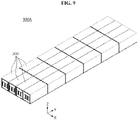
- FIG. 9 is a perspective view schematically showing a battery pack including a plurality of battery modules according to another embodiment of the present disclosure.
- the battery pack 300A includes at least two battery modules 200.
- the at least two battery modules 200 may be arranged such that the sides of the module housings 210 come into contact with each other.
- 24 battery modules 200 may be arranged in four rows and six columns. In this instance, four battery modules 200 arranged in each row may be arranged such that the sides of the module housings 210 come into contact with each other.
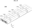
- FIG. 10 is a perspective view schematically showing a battery pack including a plurality of battery modules according to still another embodiment of the present disclosure.
- the battery pack 300B of FIG. 10 may be configured such that any one of at least two frames 212, 214, 216 provided in each of the battery modules 200A, 200B, 200C, 200D accommodates the other frame.
- any one frame 212 may be larger than the other frame 214 or another frame 216.
- the battery pack 300B of the present disclosure may be configured such that the frame 212 having the larger size provided in one battery module 200A may come into contact with the frames 214, 216 having the smaller size in the other battery module 200B.
- the plurality of battery modules is arranged as described above, it is possible to effectively reduce the size of the gap between the plurality of battery modules.
- the battery pack 300B may include 12 battery modules 200A, 200B having secondary modification as shown in FIG. 3 .
- the 12 battery modules 200A, 200B may be arranged in four rows and three columns.
- the first frame 212 of one battery module 200A may come into contact with the second frame 214 of the other battery module 200B. That is, one battery module 200A and the other battery module 200B may be symmetrically arranged in the front-rear direction. In other words, the front and rear sides of one battery module 200A and the other battery module 200B may be disposed in the opposite direction.
- FIG. 11 is a perspective view schematically showing a battery pack including a plurality of battery modules according to yet another embodiment of the present disclosure.
- the battery pack 300C may include 8 battery modules 200C, 200D having secondary modification as shown in FIG. 4 .
- the 8 battery modules 200C, 200D may be arranged in four rows and two columns.
- the first frame 212 of one battery module 200C may come into contact with the third frame 216 of the other battery module 200D.
- the second frame 214 of one battery module 200C may come into contact with the second frame 214 of the other battery module 200D. That is, one battery module 200C and the other battery module 200D may be symmetrically arranged in the front-rear direction.
- the present disclosure is configured such that the frame having a larger size in one battery module 200 comes into contact with the frame having a smaller size in the other battery module 200, thereby minimizing the size of the gap between the plurality battery modules 200, and effectively increasing the energy density of the battery pack 300. Additionally, when the plurality of battery modules 200 is arranged in contact with each other, there is no empty space, so the battery modules 200 may not lose the arrangement from external impacts. Accordingly, it is possible to effectively increase the durability of the battery pack 300.
- the battery pack 300 may include at least two battery modules 200 according to the present disclosure. Additionally, in addition to the battery module 200, the battery pack 300 may further include various types of devices for controlling the charge/discharge of the cell assembly 100, for example, a Battery Management System (BMS), a current sensor and a fuse.
- BMS Battery Management System
- the battery module 200 according to the present disclosure may be applied to vehicles such as electric vehicles or hybrid electric vehicles. That is, the vehicle according to the present disclosure may include the battery module 200.
- Battery pack 200 Battery module 110: Secondary battery 100: Cell assembly 210: Module housing 230: Busbar assembly 212, 214, 216: First frame, Second frame, Third frame 212a, 214a, 216a: Cover plate 212b, 214b, 216b: Bottom plate 212h, 214h: Coupling groove 212i, 214i, 216i: Insertion portion 212g, 214g, 216g: Insertion groove 212p, 214p, 216p: Coupling protrusion 240: Filler
Landscapes
- Chemical & Material Sciences (AREA)
- Chemical Kinetics & Catalysis (AREA)
- Electrochemistry (AREA)
- General Chemical & Material Sciences (AREA)
- Engineering & Computer Science (AREA)
- Manufacturing & Machinery (AREA)
- Battery Mounting, Suspending (AREA)
- Sealing Battery Cases Or Jackets (AREA)
Abstract
Description
- The present disclosure relates to a battery module, a battery pack comprising the battery module and a vehicle, and more particularly, to a battery module with reduced manufacturing cost and a battery pack comprising the same.
- The present application claims the benefit of
Korean Patent Application No. 10-2020-0056134 filed on May 11, 2020 - Currently, commercially available secondary batteries include nickel-cadmium batteries, nickel-hydrogen batteries, nickel-zinc batteries, lithium secondary batteries and the like, and among them, lithium secondary batteries have little or no memory effect, and thus they are gaining more attention than nickel-based secondary batteries for their advantages that recharging can be done whenever it is convenient, the self-discharge rate is very low and the energy density is high.
- A lithium secondary battery primarily uses a lithium-based oxide and a carbon material for a positive electrode active material and a negative electrode active material respectively. Additionally, the lithium secondary battery includes an electrode assembly including a positive electrode plate and a negative electrode plate respectively coated with the positive electrode active material and the negative electrode active material and a separator interposed between the positive electrode plate and the negative electrode plate, and a cylindrical battery case or a packaging in which the electrode assembly is received together with an electrolyte solution in an airtight manner.
- Recently, secondary batteries are being widely used in not only small devices such as portable electronic products but also medium- and large-scale devices such as vehicles and energy storage systems (ESSs). For use in medium- and large-scale devices, many secondary batteries are electrically connected to increase the capacity and output. In particular, pouch-type secondary batteries are widely used in medium- and large-scale devices due to their advantage that they can be easily stacked.
- More recently, with the use as a source of energy and the growing need for high capacity structures, there is an increasing demand for a battery pack including a plurality of battery modules, each battery module including a plurality of secondary batteries connected in series and/or in parallel.
- Further, secondary batteries of various sizes may be applied according to the capacity of the battery module required for products. That is, the size change of the secondary batteries leads to a size change of a module housing in which the plurality of secondary batteries is received, which requires a design modification of the module housing and a change in production equipment. The design modification greatly increases the manufacturing cost of the battery module or the battery pack, and is a factor that impedes the production cost reduction.
- The present disclosure is designed to solve the above-described problem, and therefore the present disclosure is directed to providing a battery module with reduced manufacturing cost, a battery pack comprising the same and a vehicle.
- These and other objects and advantages of the present disclosure may be understood by the following description, and will be apparent from the embodiments of the present disclosure. In addition, it will be readily appreciated that the objects and advantages of the present disclosure may be realized by means and combinations thereof.
- To achieve the above-described object, a battery module according to the present disclosure includes a cell assembly including a plurality of secondary batteries, and a module housing in which the cell assembly is received, wherein the module housing includes at least two frames capable of changing a length of the module housing according to a size of the cell assembly.
- Additionally, the at least two frames may be configured such that one frame is received in an internal space of the other frame or one frame extends from the internal space of the other frame.
- Additionally, each of the at least two frames may include a cover plate which covers a top of the cell assembly and sides of the cell assembly in a horizontal direction, and a bottom plate coupled with a bottom of the cover plate and configured to mount the cell assembly.
- Further, each of the at least two frames may have a coupling groove into which a part of other frame is inserted, and an insertion portion which is inserted into the coupling groove of the other frame.
- Additionally, each of the coupling groove and the insertion portion may extend in a lengthwise direction in which the module housing changes, and the at least two frames may be configured to be movable in the lengthwise direction when the coupling groove and the insertion portion are coupled to each other.
- Further, any one of the at least two frames may be configured to receive at least one other frame therein by the coupling of the coupling groove and the insertion portion.
- Additionally, the cover plate and the bottom plate may include an insertion groove running inward to couple the cover plate and the bottom plate, and a coupling protrusion to be configured to be inserted into the insertion groove.
- Further, the battery module may further include a fixing member configured to limit the length change of the module housing.
- Additionally, the battery module may further include a filler configured to fill an empty space of the coupling groove into which the insertion portion is not inserted.
- Meanwhile, a battery pack of the present disclosure includes at least two battery modules wherein the at least two battery modules are arranged such that sides of the module housings come into contact with each other.
- Additionally, any one of the at least two frames of the battery module may have a larger size than the other frame to receive the other frame therein, and the frame having the larger size in the one battery module and the frame having a smaller size in the other battery module may be arranged in contact with each other.
- Additionally, to achieve the above-described object, a vehicle according to the present disclosure includes the battery pack according to the present disclosure.
- According to an aspect of the present disclosure, the battery module of the present disclosure includes the module housing including the at least two frames capable of changing the length of the module housing according to the size of the cell assembly, thereby adjusting the length of the module housing according to the size of the cell assembly, so one type of module housing may be applied to the battery modules of various sizes, thereby eliminating the need to produce the module housings of different sizes for each of the battery modules of various sizes. Accordingly, the battery module of the present disclosure is easy to customize, which makes mass production easy and eliminates the need to change the design of products, thereby dramatically reducing the manufacturing cost.
- Additionally, according to an aspect of the present disclosure, the at least two frames of the present disclosure may be configured such that any one frame accommodates at least one other frame by coupling of the coupling groove and the insertion portion, thereby reducing the module housing according to the size of the cell assembly applied. Additionally, the battery module of the present disclosure may be manufactured by minimizing the size of the module housing to deliver in a compact size and making primary or secondary modification according to the size of the cell assembly in the assembling process. Accordingly, it is possible to reduce the delivery or storage cost of the battery module.
- Further, the battery pack of the present disclosure is configured such that the frame having a larger size in one battery module and the frame having a smaller size in the other battery module are arranged in contact with each other, thereby minimizing the size of the gap between the plurality of battery modules, and effectively increasing the energy density of the battery pack. Additionally, when the plurality of battery modules is arranged in contact with each other, there is no empty space, so the battery modules may not lose the arrangement from external impacts. Accordingly, it is possible to effectively increase the durability of the battery pack.
- The accompanying drawings illustrate preferred embodiments of the present disclosure, and together with the following detailed description, serve to provide a further understanding of the technical aspect of the present disclosure. However, the present disclosure should not be construed as being limited to the drawings.
-
FIG. 1 is a perspective view schematically showing a battery module according to an embodiment of the present disclosure. -
FIG. 2 is an exploded perspective view schematically showing a battery module according to an embodiment of the present disclosure. -
FIG. 3 is a perspective view schematically showing primary modification of the battery module ofFIG. 1 of the present disclosure. -
FIG. 4 is a perspective view schematically showing secondary modification of the battery module ofFIG. 1 of the present disclosure. -
FIG. 5 is a bottom perspective view schematically showing modified frames of a module housing ofFIG. 1 of the present disclosure. -
FIG. 6 is a bottom perspective view schematically showing modified cover plates of a module housing ofFIG. 4 of the present disclosure. -
FIG. 7 is a perspective view schematically showing modified bottom plates of a module housing ofFIG. 4 of the present disclosure. -
FIG. 8 is a bottom perspective view schematically showing cover plates of a battery module according to another embodiment of the present disclosure. -
FIG. 9 is a perspective view schematically showing a battery pack including a plurality of battery modules according to another embodiment of the present disclosure. -
FIG. 10 is a perspective view schematically showing a battery pack including a plurality of battery modules according to still another embodiment of the present disclosure. -
FIG. 11 is a perspective view schematically showing a battery pack including a plurality of battery modules according to yet another embodiment of the present disclosure. - Hereinafter, the preferred embodiments of the present disclosure will be described in detail with reference to the accompanying drawings. Prior to the description, it should be understood that the terms or words used in the specification and the appended claims should not be construed as being limited to general and dictionary meanings, but rather interpreted based on the meanings and concepts corresponding to the technical aspects of the present disclosure on the basis of the principle that the inventor is allowed to define the terms appropriately for the best explanation.
- Therefore, the embodiments described herein and the illustrations shown in the drawings are just a most preferred embodiment of the present disclosure, but not intended to fully describe the technical aspects of the present disclosure, so it should be understood that a variety of other equivalents and modifications could have been made thereto at the time that the application was filed.
-
FIG. 1 is a perspective view schematically showing a battery module according to an embodiment of the present disclosure. Additionally,FIG. 2 is an exploded perspective view schematically showing the battery module according to an embodiment of the present disclosure. For reference, inFIG. 1 , X axis direction is the left direction, Y axis direction is the rear direction, and Z axis direction is the up direction. - Referring to
FIGS. 1 and2 , thebattery module 200 of the present disclosure includes acell assembly 100 and amodule housing 210. Specifically, thecell assembly 100 may include a plurality ofsecondary batteries 110. In this instance, thesecondary battery 110 may be a pouch-typesecondary battery 110. In particular, the pouch-typesecondary battery 110 may include an electrode assembly, an electrolyte and a pouch case. - Here, the electrode assembly may include at least one positive electrode plate and at least negative electrode plate with a separator interposed between. More specifically, the electrode assembly may be classified into a winding type electrode assembly in which a positive electrode plate and a negative electrode plate are wound together with a separator, and a stack type electrode assembly in which a plurality of positive electrode plates and a plurality of negative electrode plate are stacked in an alternating manner with a separator interposed between.
- Additionally, the pouch case may include an outer insulating layer, a metal layer and an inner insulating layer. The pouch case may include a metal thin film, for example, an aluminum thin film, to protect the internal components such as the electrode assembly and the electrolyte solution, and enhance the electrical and chemical properties by the electrode assembly and the electrolyte solution and heat radiation. Additionally, the aluminum thin film may be interposed between the insulating layers to ensure electrical insulation from the internal components of the
secondary batteries 110 such as the electrode assembly and the electrolyte solution or other components outside of thesecondary batteries 110. - In particular, the pouch case may include 2 pouches, and at least one of the pouches may have a concave internal space. Additionally, the electrode assembly may be received in the internal space of the pouch. Additionally, a sealing portion may be provided on the outer peripheral surfaces of the 2 pouches, and when joined together, the sealing portions may hermetically seal the internal space in which the electrode assembly is received.
- Each pouch-type
secondary battery 110 may include anelectrode lead 111, and theelectrode lead 111 may include a positive electrode lead and a negative electrode lead. - More specifically, the
electrode lead 111 may extend frontward or rearward from the sealing portion disposed at the front or rear outer periphery of the pouch case. Additionally, theelectrode lead 111 may serve as an electrode terminal of thesecondary battery 110. For example, as shown inFIG. 2 , oneelectrode lead 111 may extend frontward from thesecondary battery 110, and theother electrode lead 111 may extend rearward from thesecondary battery 110. - According to this configuration of the present disclosure, it is possible to eliminate interference between the positive electrode lead and the negative electrode lead in one
secondary battery 110, thereby increasing the area of theelectrode lead 111 and facilitating a welding process between theelectrode lead 111 and a busbar provided in abusbar assembly 230. - The
battery module 200 may include the plurality of pouch-typesecondary batteries 110 stacked and arranged in at least one direction. For example, as shown inFIG. 2 , the plurality of pouch-typesecondary batteries 110 may be horizontally stacked side by side. In this instance, each pouch-typesecondary battery 110 may stand in a direction approximately perpendicular to the ground with the two wide surfaces disposed on the left and right sides respectively and the sealing portions disposed in the up, down, front and rear directions, when viewed from the front side. In other words, eachsecondary battery 110 may stand vertically. - The configuration of the pouch-type
secondary batteries 110 is obvious to those skilled in the art, and its detailed description is omitted herein. Additionally, thecell assembly 100 according to the present disclosure may employ various types of secondary batteries well known at the time of filing the patent application. - Additionally, the
battery module 200 of the present disclosure may include the busbar electrically connecting the plurality ofsecondary batteries 110 of thecell assembly 100. The busbar may be mounted on a busbar frame of the busbar assembly. The busbar may include a metal material. The busbar may be disposed on each of the front and rear sides of thecell assembly 100. - Meanwhile, the
module housing 210 may serve as a case in thebattery module 200. Accordingly, themodule housing 210 serves to provide structural stability to thebattery module 200, and protect the components received therein such as thecell assembly 100 from external mechanical elements such as impacts or materials. To this end, themodule housing 210 may include metals such as steel or aluminum or nonconductive plastics. -
FIG. 3 is a perspective view schematically showing primary modification of the battery module ofFIG. 1 of the present disclosure. Additionally,FIG. 4 is a perspective view schematically showing secondary modification of the battery module ofFIG. 1 of the present disclosure. - Referring to
FIGS. 3 and4 together withFIGS. 1 and2 , themodule housing 210 may include at least twoframes frames module housing 210 according to the size of thecell assembly 100. For example, when the length in the front-rear direction of thecell assembly 100 received in thebattery module 200 shown inFIG. 3 is longer than the length of thecell assembly 100 shown inFIG. 2 , thebattery module 200 may have primary modification so that the length of themodule housing 210 in the front-rear direction increases about twice. Additionally, themodule housing 210 of thebattery module 200 shown inFIG. 4 may have secondary modification so that the length in the front-rear direction (Y axis direction) increases about 3 times on the basis of the length of themodule housing 210 shown inFIG. 1 . - According to this configuration of the present disclosure, the
module housing 210 includes the at least twoframes module housing 210 according to the size of thecell assembly 100, thereby adjusting the length of themodule housing 210 according to the size of thecell assembly 100, so one type ofmodule housing 210 may be applied to thebattery modules 200 of various sizes, thereby eliminating the need to produce themodule housings 210 of different sizes for each of thebattery modules 200 of various sizes. Accordingly, thebattery module 200 of the present disclosure is easy to customize, which makes mass production easy and eliminates the need to change the design of products, thereby dramatically reducing the manufacturing cost. - Additionally, the at least two
frames cell assembly 100. For example, the at least twoframes frames cell assembly 100 may be inserted in the front-rear direction. - Further, the at least two
frames frame 212 accommodates at least oneother frame frames other frame frame 212. For example, as shown inFIG. 1 , thesecond frame 214 and thethird frame 216 may be received in the internal space of thefirst frame 212. For example, as shown inFIG. 3 , thethird frame 216 may be received in the internal space of thesecond frame 214. Additionally, thesecond frame 214 may be disposed such that it extends rearward from the internal space of thefirst frame 212. - Referring back to
FIG. 2 , the at least twoframes cover plates bottom plates cover plates cell assembly 100 and the sides of thecell assembly 100 in the horizontal direction. For example, as shown inFIG. 2 , thecover plates module housing 210 may have an upper wall, a left side wall and a right side wall to cover the top and the left and right sides of thecell assembly 100 respectively. - Additionally, the
cell assembly 100 may be mounted on thebottom plates bottom plates cell assembly 100. Further, thebottom plates cover plates bottom plates cover plates cover plates bottom plates - According to this configuration of the present disclosure, the
module housing 210 of the present disclosure includes the cover plates and the bottom plates which are separated from each other, thereby making it easy to mount thecell assembly 100 therein. For example, thecell assembly 100 may be mounted in themodule housing 210 by mounting thecell assembly 100 on the bottom plate and coupling the cover plate with the bottom plate. -
FIG. 5 is a bottom perspective view schematically showing the modified frames of the module housing ofFIG. 1 of the present disclosure.FIG. 6 is a bottom perspective view schematically showing the modified cover plates of the module housing ofFIG. 4 of the present disclosure. Additionally,FIG. 7 is a perspective view schematically showing the modified bottom plates of the module housing ofFIG. 4 of the present disclosure. - Referring to
FIGS. 5 to 7 together withFIGS. 3 and4 , the at least twoframes coupling grooves insertion portions insertion portion 214i of oneframe 214 may be inserted into thecoupling groove 212h of theother frame 212. On the contrary, theinsertion portion 214i of theother frame 214 may be inserted into thecoupling groove 212h of oneframe 212. - For example, referring to
FIGS. 5 and6 , themodule housing 210 of the present disclosure includes thefirst frame 212, thesecond frame 214 and thethird frame 216, and thefirst frame 212 includes thecover plate 212a and thebottom plate 212b. Thesecond frame 214 includes thecover plate 214a and thebottom plate 214b. Thethird frame 216 includes thecover plate 216a and thebottom plate 216b. Among the threeframes first frame 212 of the larger size, thesecond frame 214 of the intermediate size, and thethird frame 216 of the smaller size in the order of size. - Additionally, the
cover plate 212a of thefirst frame 212 may include thecoupling groove 212h and theinsertion portion 212i. Thecover plate 214a of thesecond frame 214 may include thecoupling groove 214h and theinsertion portion 214i. Additionally, thecover plate 216a of thethird frame 216 may include the coupling groove and theinsertion portion 216i. - For example, as shown in
FIGS. 5 and6 , thecover plate 212a of thefirst frame 212 may include thecoupling groove 212h into which theinsertion portion 214i of thecover plate 214a of at least one of thesecond frame 214 or thethird frame 216 is inserted. Thecover plate 214a of thesecond frame 214 may include thecoupling groove 214h into which theinsertion portion 216i of thecover plate 216a of thethird frame 216 is inserted. Thecover plate 216a of thethird frame 216 may include theinsertion portion 216i which is inserted into thecoupling groove 212h of thecover plate 212a of at least one of thefirst frame 212 or thesecond frame 214. - Further, the
bottom plates coupling grooves insertion portions FIG. 7 , thebottom plate 212b of thefirst frame 212 may include thecoupling groove 212h into which theinsertion portion 214i of thebottom plate 214b of at least one of thesecond frame 214 or thethird frame 216 is inserted. Thebottom plate 214b of thesecond frame 214 may include thecoupling groove 214h into which theinsertion portion 216i of thebottom plate 216b of thethird frame 216 is inserted. Thebottom plate 216b of thethird frame 216 may include theinsertion portion 216i which is inserted into thecoupling groove 212h of thebottom plate 212b of at least one of thefirst frame 212 or thesecond frame 214. - Additionally, each of the
coupling grooves module housing 210 changes. Each of theinsertion portions module housing 210 changes. - For example, as shown in
FIG. 6 , thecover plates first frame 212 and thesecond frame 214 may include thecoupling grooves cover plates second frame 214 and thethird frame 216 may include theinsertion portions - For example, as shown in
FIG. 7 , thebottom plates first frame 212 and thesecond frame 214 may include thecoupling grooves bottom plates second frame 214 and thethird frame 216 may include theinsertion portions - Further, the at least two
frames FIGS. 5 and6 , thecover plates bottom plate first frame 212, thesecond frame 214 and thethird frame 216 may be respectively configured to slidably move in the front-rear direction when thecoupling grooves insertion portions - According to this configuration of the present disclosure, the at least two
frames module housing 210 according to the size of thecell assembly 100 applied to themodule housing 210. Accordingly, it is possible to effectively reduce the manufacturing cost of thebattery module 200. - Meanwhile, referring to
FIGS. 2 and5 to 7 , the at least twoframes frame 214 is received in theother frame 212 by insertion of theinsertion portion 214i of theframe 214 into thecoupling groove 212h of theframe 212. - For example, as shown in
FIG. 5 , thecover plates second frame 214 and thethird frame 216 may be received in thecover plate 212a of thefirst frame 212 by insertion of theinsertion portions cover plates second frame 214 and thethird frame 216 into thecoupling groove 212h of thecover plate 212a of thefirst frame 212. Additionally, thecover plate 216a of thethird frame 216 may be received in thecover plate 214a of thesecond frame 214 by coupling of thecoupling groove 214h and theinsertion portion 216i. That is, among the threecover plates cover plate 212a may have the largest size, theother cover plate 214a may have the intermediate size, and the remainingcover plate 216a may have the smallest size. - For example, as shown in
FIG. 2 , thebottom plates second frame 214 and thethird frame 216 may be respectively received in thebottom plate 212b of thefirst frame 212 by insertion of theinsertion portions bottom plates second frame 214 and thethird frame 216 into thecoupling groove 212h of thebottom plate 212b of thefirst frame 212. - Additionally, the
bottom plate 214b of thesecond frame 214 may be received in thebottom plate 216b of thethird frame 216 by coupling of thecoupling groove 214h and theinsertion portion 216i. In this instance, among the threebottom plates bottom plate 212b may have the largest size, the otherbottom plate 214b may have the intermediate size, and the remainingbottom plate 216b may have the smallest size. - According to this configuration of the present disclosure, the at least two
frames frame 212 accommodates at least oneother frame coupling groove 212h and theinsertion portion 214i, thereby reducing themodule housing 210 according to the size of thecell assembly 100 applied. - Further, the
battery module 200 of the present disclosure may be manufactured by minimizing the size of themodule housing 210 to deliver in a compact size and making primary or secondary modification according to the size of thecell assembly 100 in the assembling process. Accordingly, it is possible to reduce the delivery or storage cost of thebattery module 200. - Referring back to
FIGS. 6 and7 , thecover plates bottom plates cover plates insertion grooves bottom plates coupling protrusions insertion grooves insertion grooves coupling protrusions insertion grooves coupling protrusions - For example, as shown in
FIGS. 6 and7 , thecover plates first frame 212, thesecond frame 214 and thethird frame 216 may include, on the bottom surface, theinsertion grooves coupling protrusions bottom plates first frame 212, thesecond frame 214, and thethird frame 216 are inserted respectively. - Further, the at least two frames may be configured to move in one direction when the
insertion grooves coupling protrusions FIGS. 6 and7 , theinsertion grooves cover plates FIG. 7 , thecoupling protrusions bottom plates - According to this configuration of the present disclosure, the present disclosure includes the insertion grooves and the coupling protrusions, so it is possible to easily couple the cover plates of the
first frame 212, thesecond frame 214 and thethird frame 216 to the bottom plates 21b, and when each cover plate and each bottom plate coupled to each other move in the front-rear direction, the size of themodule housing 210 may be changed. - Meanwhile, referring back to
FIGS. 2 and5 , thebattery module 200 of the present disclosure may further include a fixing member (not shown) configured to limit the length change of themodule housing 210. For example, the fixing member may be an adhesive. The adhesive may be attached to an adhesive surface between thefirst frame 212, thesecond frame 214 and thethird frame 216. - For example, as shown in
FIG. 6 , the adhesive may be attached between the inner surface of thecoupling groove 212h of thefirst frame 212 and the outer surface of theinsertion portion 214i of thesecond frame 214 to combine thefirst frame 212 and thesecond frame 214. The adhesive may be attached between the inner surface of the coupling groove 21h of thesecond frame 214 and the outer surface of the insertion portion 21i of thethird frame 216 to combine thesecond frame 214 and thethird frame 216. - According to this configuration of the present disclosure, the present disclosure further includes the fixing member configured to limit the length change of the
module housing 210, thereby preventing the length of themodule housing 210 from changing after the manufacturing of thebattery module 200 is completed. Accordingly, it is possible to increase the manufacturing productivity of thebattery module 200. It is possible to prevent faults such as the size change of themodule housing 210 by external impacts after the products are manufactured. -
FIG. 8 is a bottom perspective view schematically showing cover plates of a battery module according to another embodiment of the present disclosure. - Referring to
FIG. 8 , themodule housing 210 of thebattery module 200 according to another embodiment of the present disclosure may further include afiller 240 in each of thecoupling grooves module housing 210 ofFIG. 6 . For example, as shown inFIG. 8 , thefiller 240 may be configured to fill an empty space of thecoupling grooves insertion portions filler 240 may be configured to be cured after it is filled in each of thecoupling grooves filler 240 may be polymer resin. For example, thefiller 240 may be epoxy resin. -
FIG. 9 is a perspective view schematically showing a battery pack including a plurality of battery modules according to another embodiment of the present disclosure. - Referring to
FIG. 9 , thebattery pack 300A according to an embodiment of the present disclosure includes at least twobattery modules 200. The at least twobattery modules 200 may be arranged such that the sides of themodule housings 210 come into contact with each other. For example, as shown inFIG. 9 , 24battery modules 200 may be arranged in four rows and six columns. In this instance, fourbattery modules 200 arranged in each row may be arranged such that the sides of themodule housings 210 come into contact with each other. -
FIG. 10 is a perspective view schematically showing a battery pack including a plurality of battery modules according to still another embodiment of the present disclosure. - Referring to
FIG. 10 together withFIG. 3 , first, thebattery pack 300B ofFIG. 10 may be configured such that any one of at least twoframes battery modules frame 212 may be larger than theother frame 214 or anotherframe 216. - By this structural feature, the
battery pack 300B of the present disclosure may be configured such that theframe 212 having the larger size provided in onebattery module 200A may come into contact with theframes other battery module 200B. When the plurality of battery modules is arranged as described above, it is possible to effectively reduce the size of the gap between the plurality of battery modules. - For example, referring to
FIG. 10 , thebattery pack 300B according to another embodiment may include 12battery modules FIG. 3 . The 12battery modules first frame 212 of onebattery module 200A may come into contact with thesecond frame 214 of theother battery module 200B. That is, onebattery module 200A and theother battery module 200B may be symmetrically arranged in the front-rear direction. In other words, the front and rear sides of onebattery module 200A and theother battery module 200B may be disposed in the opposite direction. -
FIG. 11 is a perspective view schematically showing a battery pack including a plurality of battery modules according to yet another embodiment of the present disclosure. - Additionally, referring to
FIG. 11 together withFIG. 4 , thebattery pack 300C according to yet another embodiment of the present disclosure may include 8battery modules FIG. 4 . The 8battery modules first frame 212 of onebattery module 200C may come into contact with thethird frame 216 of theother battery module 200D. Thesecond frame 214 of onebattery module 200C may come into contact with thesecond frame 214 of theother battery module 200D. That is, onebattery module 200C and theother battery module 200D may be symmetrically arranged in the front-rear direction. - According to this configuration of the present disclosure, the present disclosure is configured such that the frame having a larger size in one
battery module 200 comes into contact with the frame having a smaller size in theother battery module 200, thereby minimizing the size of the gap between theplurality battery modules 200, and effectively increasing the energy density of the battery pack 300. Additionally, when the plurality ofbattery modules 200 is arranged in contact with each other, there is no empty space, so thebattery modules 200 may not lose the arrangement from external impacts. Accordingly, it is possible to effectively increase the durability of the battery pack 300. - The battery pack 300 according to the present disclosure may include at least two
battery modules 200 according to the present disclosure. Additionally, in addition to thebattery module 200, the battery pack 300 may further include various types of devices for controlling the charge/discharge of thecell assembly 100, for example, a Battery Management System (BMS), a current sensor and a fuse. - Additionally, the
battery module 200 according to the present disclosure may be applied to vehicles such as electric vehicles or hybrid electric vehicles. That is, the vehicle according to the present disclosure may include thebattery module 200. - Meanwhile, the terms indicating directions as used herein such as upper, lower, left, exact, front and rear are used for convenience of description only, and it is obvious to those skilled in the art that the term may change depending on the position of the stated element or an observer.
- While the present disclosure has been hereinabove described with regard to a limited number of embodiments and drawings, the present disclosure is not limited thereto and it is obvious to those skilled in the art that various modifications and changes may be made thereto within the technical aspects of the present disclosure and the equivalent scope of the appended claims.
-
300: Battery pack 200: Battery module 110: Secondary battery 100: Cell assembly 210: Module housing 230: Busbar assembly 212, 214, 216: First frame, Second frame, Third frame 212a, 214a, 216a: Cover plate 212b, 214b, 216b: Bottom plate 212h, 214h: Coupling groove 212i, 214i, 216i: Insertion portion 212g, 214g, 216g: Insertion groove 212p, 214p, 216p: Coupling protrusion 240: Filler
Claims (12)
- A battery module comprising:a cell assembly including a plurality of secondary batteries; anda module housing in which the cell assembly is received,wherein the module housing includes at least two frames capable of changing a length of the module housing according to a size of the cell assembly.
- The battery module according to claim 1, wherein the at least two frames are configured such that one frame is received in an internal space of the other frame or one frame extends from the internal space of the other frame.
- The battery module according to claim 1, wherein each of the at least two frames includes:a cover plate which covers a top of the cell assembly and sides of the cell assembly in a horizontal direction; anda bottom plate coupled with a bottom of the cover plate and configured to mount the cell assembly.
- The battery module according to claim 3, wherein each of the at least two frames has a coupling groove into which a part of other frame is inserted, and an insertion portion which is inserted into the coupling groove of the other frame.
- The battery module according to claim 4, wherein each of the coupling groove and the insertion portion extends in a lengthwise direction in which the module housing changes, and
the at least two frames are configured to be movable in the lengthwise direction when the coupling groove and the insertion portion are coupled to each other. - The battery module according to claim 4, wherein any one of the at least two frames is configured to receive at least one other frame therein by the coupling of the coupling groove and the insertion portion.
- The battery module according to claim 4, wherein the cover plate and the bottom plate include an insertion groove running inward to couple the cover plate and the bottom plate, and a coupling protrusion to be configured to be inserted into the insertion groove.
- The battery module according to claim 4, further comprising:
a fixing member configured to limit the length change of the module housing. - The battery module according to claim 4, further comprising:
a filler configured to fill an empty space of the coupling groove into which the insertion portion is not inserted. - A battery pack comprising at least two battery modules according to any one of claims 1 to 9, wherein the at least two battery modules are arranged such that sides of the module housings come into contact with each other.
- The battery pack according to claim 10, wherein any one of the at least two frames of the battery module has a larger size than the other frame to receive the other frame therein, and
the frame having the larger size in the one battery module and the frame having a smaller size in the other battery module are arranged in contact with each other. - A vehicle comprising at least one battery pack according to claim 11.
Applications Claiming Priority (2)
| Application Number | Priority Date | Filing Date | Title |
|---|---|---|---|
| KR20200056134 | 2020-05-11 | ||
| PCT/KR2021/005469 WO2021230542A1 (en) | 2020-05-11 | 2021-04-29 | Battery module, battery pack comprising same battery module, and vehicle |
Publications (3)
| Publication Number | Publication Date |
|---|---|
| EP4027442A1 true EP4027442A1 (en) | 2022-07-13 |
| EP4027442A4 EP4027442A4 (en) | 2023-05-10 |
| EP4027442B1 EP4027442B1 (en) | 2026-04-08 |
Family
ID=78524420
Family Applications (1)
| Application Number | Title | Priority Date | Filing Date |
|---|---|---|---|
| EP21803176.3A Active EP4027442B1 (en) | 2020-05-11 | 2021-04-29 | Battery module, battery pack comprising battery module, and vehicle |
Country Status (6)
| Country | Link |
|---|---|
| US (1) | US12368202B2 (en) |
| EP (1) | EP4027442B1 (en) |
| JP (1) | JP7348381B2 (en) |
| KR (1) | KR20210137910A (en) |
| CN (1) | CN114514650B (en) |
| WO (1) | WO2021230542A1 (en) |
Cited By (1)
| Publication number | Priority date | Publication date | Assignee | Title |
|---|---|---|---|---|
| EP4657626A1 (en) * | 2024-05-31 | 2025-12-03 | Volvo Truck Corporation | Battery system for vehicle |
Families Citing this family (3)
| Publication number | Priority date | Publication date | Assignee | Title |
|---|---|---|---|---|
| KR20230119551A (en) * | 2022-02-07 | 2023-08-16 | 주식회사 엘지에너지솔루션 | Battery module and battery pack including the same and vehicle including the same |
| DE102023133153A1 (en) * | 2023-11-28 | 2025-05-28 | Audi Aktiengesellschaft | Modular system for producing an electrical energy storage device for a motor vehicle, method for producing such an energy storage device, electrical energy storage device and motor vehicle |
| CN119812648B (en) * | 2024-12-31 | 2025-09-09 | 深圳哲思锂电循环科技有限公司 | A mobile DC energy storage device |
Family Cites Families (22)
| Publication number | Priority date | Publication date | Assignee | Title |
|---|---|---|---|---|
| JPS56101862U (en) * | 1979-12-30 | 1981-08-10 | ||
| JP3670925B2 (en) * | 2000-03-08 | 2005-07-13 | 三洋電機株式会社 | Assembled battery |
| JP3131680U (en) * | 2007-02-28 | 2007-05-17 | 三進金属工業株式会社 | Storage rack |
| CN201044253Y (en) | 2007-04-18 | 2008-04-02 | 钟志宏 | Electricity charger for cell |
| KR200439828Y1 (en) | 2007-05-16 | 2008-05-08 | 주식회사 프로파워 | Battery pack case |
| CN103053045B (en) | 2010-08-24 | 2016-03-30 | 日本碍子株式会社 | Assembled battery support |
| KR20140026098A (en) * | 2012-08-24 | 2014-03-05 | 주식회사 엘지화학 | Power storage system and rack housing system applied for the same |
| CN104981920B (en) | 2013-02-14 | 2017-12-15 | 三洋电机株式会社 | Battery module |
| CN108054462A (en) | 2014-11-10 | 2018-05-18 | 深圳市大疆创新科技有限公司 | Battery and its heat management device and the UAV with the battery |
| KR101726928B1 (en) * | 2014-11-25 | 2017-04-13 | 주식회사 엘지화학 | Battery rack assembly |
| KR102411156B1 (en) * | 2015-12-29 | 2022-06-21 | 에이치그린파워 주식회사 | Extensible stack module housing and Battery module having the same |
| KR20180041536A (en) | 2016-10-14 | 2018-04-24 | 강진우 | Recycling pack for batteries |
| KR102148993B1 (en) * | 2017-06-13 | 2020-08-27 | 주식회사 엘지화학 | Battery module |
| KR102258816B1 (en) * | 2017-06-27 | 2021-05-31 | 주식회사 엘지에너지솔루션 | Battery Module |
| KR102201332B1 (en) | 2017-10-24 | 2021-01-08 | 주식회사 엘지화학 | Battery pack and vehicle comprising the same |
| US10601003B2 (en) * | 2017-10-30 | 2020-03-24 | Lg Chem, Ltd. | Battery module and method of assembling the battery module |
| CN107933276A (en) * | 2017-11-30 | 2018-04-20 | 马美英 | It is a kind of easily to replace rechargeable battery and the electric automobile of regulating cell storehouse size |
| KR20190083887A (en) * | 2018-01-05 | 2019-07-15 | 주식회사 엘지화학 | The Secondary Battery for Adjusting Length |
| KR102554132B1 (en) * | 2018-01-26 | 2023-07-12 | 주식회사 엘지에너지솔루션 | Cylindrical Battery Case with Adjustable Length |
| KR102038456B1 (en) | 2018-02-27 | 2019-10-30 | 이건성 | Volume Variable Type Cigarette Case |
| CN108470859B (en) * | 2018-03-08 | 2024-02-09 | 福建猛狮新能源科技有限公司 | Starter battery, battery body thereof, and variable case |
| KR102202031B1 (en) | 2018-11-14 | 2021-01-12 | 아주대학교 산학협력단 | Method and apparatus for analyzing radar cross section (RCS) of complex structure |
-
2021
- 2021-04-29 WO PCT/KR2021/005469 patent/WO2021230542A1/en not_active Ceased
- 2021-04-29 CN CN202180005413.7A patent/CN114514650B/en active Active
- 2021-04-29 JP JP2022506500A patent/JP7348381B2/en active Active
- 2021-04-29 KR KR1020210056062A patent/KR20210137910A/en active Pending
- 2021-04-29 EP EP21803176.3A patent/EP4027442B1/en active Active
- 2021-04-29 US US17/768,086 patent/US12368202B2/en active Active
Cited By (1)
| Publication number | Priority date | Publication date | Assignee | Title |
|---|---|---|---|---|
| EP4657626A1 (en) * | 2024-05-31 | 2025-12-03 | Volvo Truck Corporation | Battery system for vehicle |
Also Published As
| Publication number | Publication date |
|---|---|
| CN114514650B (en) | 2024-09-27 |
| US20230282915A1 (en) | 2023-09-07 |
| WO2021230542A1 (en) | 2021-11-18 |
| JP2022542452A (en) | 2022-10-03 |
| KR20210137910A (en) | 2021-11-18 |
| EP4027442B1 (en) | 2026-04-08 |
| CN114514650A (en) | 2022-05-17 |
| JP7348381B2 (en) | 2023-09-20 |
| EP4027442A4 (en) | 2023-05-10 |
| US12368202B2 (en) | 2025-07-22 |
Similar Documents
| Publication | Publication Date | Title |
|---|---|---|
| EP3758089B1 (en) | Battery module including heat shrinkable tube | |
| EP4027442B1 (en) | Battery module, battery pack comprising battery module, and vehicle | |
| US8551631B2 (en) | Assembled battery, and vehicle equipped with the assembled battery | |
| CN103098256B (en) | Pouch case and battery pack including same | |
| US9548475B2 (en) | Battery cell of irregular structure and battery module employed with the same | |
| EP4207461A1 (en) | Battery pack and automobile including same | |
| EP4050715B1 (en) | Battery pack, electronic device, and vehicle | |
| EP4175041B1 (en) | Battery module, battery pack, and vehicle | |
| EP4009426A1 (en) | Battery pack, electronic device and vehicle | |
| US11367929B2 (en) | Electrical assembly and battery pack including electrical assembly | |
| EP4044340B1 (en) | Battery pack with improved vibration resistance | |
| US20230148174A1 (en) | Battery, electrical device, and method and device for manufacturing battery | |
| US20190296388A1 (en) | Battery cell for electric vehicle battery pack | |
| KR20150137840A (en) | Unit battery module and Battery module having the same | |
| KR20140072689A (en) | Battery Module Assembly | |
| US20170054182A1 (en) | Method for producing a battery cell and battery cell | |
| US20240322391A1 (en) | Power storage module | |
| EP3671941B1 (en) | Secondary battery and battery pack including the same | |
| KR20210122106A (en) | Stack of battery cells and method for assembling the same, battery module and vehicle | |
| KR20170078359A (en) | Battery module and Method for assembling the same | |
| KR20160054268A (en) | Secondary battery cell and battery module including the same | |
| EP4567990A1 (en) | Battery pack case and battery pack comprising same | |
| KR20260027763A (en) | Secondary battery, and battery module, battery pack and vehicle comprising the same | |
| KR20190008654A (en) | Battery Pack | |
| KR20260017591A (en) | Secondary battery, and battery module, battery pack and vehicle comprising same |
Legal Events
| Date | Code | Title | Description |
|---|---|---|---|
| STAA | Information on the status of an ep patent application or granted ep patent |
Free format text: STATUS: THE INTERNATIONAL PUBLICATION HAS BEEN MADE |
|
| PUAI | Public reference made under article 153(3) epc to a published international application that has entered the european phase |
Free format text: ORIGINAL CODE: 0009012 |
|
| STAA | Information on the status of an ep patent application or granted ep patent |
Free format text: STATUS: REQUEST FOR EXAMINATION WAS MADE |
|
| 17P | Request for examination filed |
Effective date: 20220408 |
|
| AK | Designated contracting states |
Kind code of ref document: A1 Designated state(s): AL AT BE BG CH CY CZ DE DK EE ES FI FR GB GR HR HU IE IS IT LI LT LU LV MC MK MT NL NO PL PT RO RS SE SI SK SM TR |
|
| REG | Reference to a national code |
Ref country code: DE Ref legal event code: R079 Free format text: PREVIOUS MAIN CLASS: H01M0050200000 Ipc: H01M0050211000 Ref document number: 602021051742 Country of ref document: DE |
|
| A4 | Supplementary search report drawn up and despatched |
Effective date: 20230406 |
|
| RIC1 | Information provided on ipc code assigned before grant |
Ipc: H01M 50/267 20210101ALI20230331BHEP Ipc: H01M 50/211 20210101AFI20230331BHEP |
|
| DAV | Request for validation of the european patent (deleted) | ||
| DAX | Request for extension of the european patent (deleted) | ||
| GRAP | Despatch of communication of intention to grant a patent |
Free format text: ORIGINAL CODE: EPIDOSNIGR1 |
|
| STAA | Information on the status of an ep patent application or granted ep patent |
Free format text: STATUS: GRANT OF PATENT IS INTENDED |
|
| RIC1 | Information provided on ipc code assigned before grant |
Ipc: H01M 50/211 20210101AFI20251017BHEP Ipc: H01M 50/267 20210101ALI20251017BHEP |
|
| INTG | Intention to grant announced |
Effective date: 20251104 |
|
| P01 | Opt-out of the competence of the unified patent court (upc) registered |
Free format text: CASE NUMBER: UPC_APP_0015338_4027442/2025 Effective date: 20251201 |
|
| GRAS | Grant fee paid |
Free format text: ORIGINAL CODE: EPIDOSNIGR3 |
|
| GRAA | (expected) grant |
Free format text: ORIGINAL CODE: 0009210 |
|
| STAA | Information on the status of an ep patent application or granted ep patent |
Free format text: STATUS: THE PATENT HAS BEEN GRANTED |
|
| AK | Designated contracting states |
Kind code of ref document: B1 Designated state(s): AL AT BE BG CH CY CZ DE DK EE ES FI FR GB GR HR HU IE IS IT LI LT LU LV MC MK MT NL NO PL PT RO RS SE SI SK SM TR |
|
| REG | Reference to a national code |
Ref country code: CH Ref legal event code: F10 Free format text: ST27 STATUS EVENT CODE: U-0-0-F10-F00 (AS PROVIDED BY THE NATIONAL OFFICE) Effective date: 20260408 Ref country code: GB Ref legal event code: FG4D |
|
| REG | Reference to a national code |
Ref country code: DE Ref legal event code: R096 Ref document number: 602021051742 Country of ref document: DE |