EP4027398A1 - Piezoelectric actuator - Google Patents
Piezoelectric actuator Download PDFInfo
- Publication number
- EP4027398A1 EP4027398A1 EP20860274.8A EP20860274A EP4027398A1 EP 4027398 A1 EP4027398 A1 EP 4027398A1 EP 20860274 A EP20860274 A EP 20860274A EP 4027398 A1 EP4027398 A1 EP 4027398A1
- Authority
- EP
- European Patent Office
- Prior art keywords
- peripheral surface
- protrusion
- end portion
- piezoelectric actuator
- cylinder
- Prior art date
- Legal status (The legal status is an assumption and is not a legal conclusion. Google has not performed a legal analysis and makes no representation as to the accuracy of the status listed.)
- Granted
Links
Images



Classifications
-
- H—ELECTRICITY
- H10—SEMICONDUCTOR DEVICES; ELECTRIC SOLID-STATE DEVICES NOT OTHERWISE PROVIDED FOR
- H10N—ELECTRIC SOLID-STATE DEVICES NOT OTHERWISE PROVIDED FOR
- H10N30/00—Piezoelectric or electrostrictive devices
- H10N30/80—Constructional details
- H10N30/88—Mounts; Supports; Enclosures; Casings
- H10N30/886—Additional mechanical prestressing means, e.g. springs
-
- H—ELECTRICITY
- H10—SEMICONDUCTOR DEVICES; ELECTRIC SOLID-STATE DEVICES NOT OTHERWISE PROVIDED FOR
- H10N—ELECTRIC SOLID-STATE DEVICES NOT OTHERWISE PROVIDED FOR
- H10N30/00—Piezoelectric or electrostrictive devices
- H10N30/80—Constructional details
- H10N30/88—Mounts; Supports; Enclosures; Casings
-
- H—ELECTRICITY
- H02—GENERATION; CONVERSION OR DISTRIBUTION OF ELECTRIC POWER
- H02N—ELECTRIC MACHINES NOT OTHERWISE PROVIDED FOR
- H02N2/00—Electric machines in general using piezoelectric effect, electrostriction or magnetostriction
- H02N2/02—Electric machines in general using piezoelectric effect, electrostriction or magnetostriction producing linear motion, e.g. actuators; Linear positioners ; Linear motors
- H02N2/04—Constructional details
-
- H—ELECTRICITY
- H10—SEMICONDUCTOR DEVICES; ELECTRIC SOLID-STATE DEVICES NOT OTHERWISE PROVIDED FOR
- H10N—ELECTRIC SOLID-STATE DEVICES NOT OTHERWISE PROVIDED FOR
- H10N30/00—Piezoelectric or electrostrictive devices
- H10N30/20—Piezoelectric or electrostrictive devices with electrical input and mechanical output, e.g. functioning as actuators or vibrators
-
- H—ELECTRICITY
- H10—SEMICONDUCTOR DEVICES; ELECTRIC SOLID-STATE DEVICES NOT OTHERWISE PROVIDED FOR
- H10N—ELECTRIC SOLID-STATE DEVICES NOT OTHERWISE PROVIDED FOR
- H10N30/00—Piezoelectric or electrostrictive devices
- H10N30/20—Piezoelectric or electrostrictive devices with electrical input and mechanical output, e.g. functioning as actuators or vibrators
- H10N30/204—Piezoelectric or electrostrictive devices with electrical input and mechanical output, e.g. functioning as actuators or vibrators using bending displacement, e.g. unimorph, bimorph or multimorph cantilever or membrane benders
-
- H—ELECTRICITY
- H10—SEMICONDUCTOR DEVICES; ELECTRIC SOLID-STATE DEVICES NOT OTHERWISE PROVIDED FOR
- H10N—ELECTRIC SOLID-STATE DEVICES NOT OTHERWISE PROVIDED FOR
- H10N30/00—Piezoelectric or electrostrictive devices
- H10N30/50—Piezoelectric or electrostrictive devices having a stacked or multilayer structure
-
- H—ELECTRICITY
- H10—SEMICONDUCTOR DEVICES; ELECTRIC SOLID-STATE DEVICES NOT OTHERWISE PROVIDED FOR
- H10N—ELECTRIC SOLID-STATE DEVICES NOT OTHERWISE PROVIDED FOR
- H10N30/00—Piezoelectric or electrostrictive devices
- H10N30/80—Constructional details
- H10N30/87—Electrodes or interconnections, e.g. leads or terminals
-
- H—ELECTRICITY
- H10—SEMICONDUCTOR DEVICES; ELECTRIC SOLID-STATE DEVICES NOT OTHERWISE PROVIDED FOR
- H10N—ELECTRIC SOLID-STATE DEVICES NOT OTHERWISE PROVIDED FOR
- H10N30/00—Piezoelectric or electrostrictive devices
- H10N30/80—Constructional details
- H10N30/87—Electrodes or interconnections, e.g. leads or terminals
- H10N30/871—Single-layered electrodes of multilayer piezoelectric or electrostrictive devices, e.g. internal electrodes
Definitions
- the present disclosure relates to a piezoelectric actuator.
- a known encapsulated multilayer piezoelectric actuator includes a multilayer piezoelectric element accommodated in an expandable metal case.
- the multilayer piezoelectric element includes a stack of alternate piezoelectric ceramic layers and internal electrode layers.
- the metal case includes a hollow member to allow communication between inside and outside.
- the hollow member is sealed with upper and lower caps to block communication between inside and outside the metal case (refer to, for example, Patent Literature 1).
- the expandable hollow member is joined to the upper and lower caps and thus expands in response to expansion of the piezoelectric element.
- This structure is likely to cause stress concentration at joints between the hollow member and the upper and lower caps, possibly degrading the sealing of the hollow member.
- the known piezoelectric actuator is to be more durable.
- Patent Literature 1 Japanese Unexamined Patent Application Publication No. 2010-192832
- a piezoelectric actuator includes a piezoelectric element, and a case accommodating the piezoelectric element.
- the case is deformable to conform with expansion or contraction of the piezoelectric element.
- the case includes a cylinder including a first end portion being open, and a first cap including a first end plate being circular and a first protrusion being annular.
- the first protrusion is located on a first surface of the first end plate and protrudes perpendicularly to the first surface.
- the cylinder includes the first end portion receiving the first protrusion on the first cap.
- the first end portion includes an inner peripheral surface joined to an outer peripheral surface of the first protrusion.
- the first end portion includes an edge located nearer an edge of the first protrusion than the first surface of the first end plate in an axial direction of the cylinder.
- FIG. 1 is a schematic perspective view of a piezoelectric actuator 10 according to the first embodiment.
- FIG. 2 is a schematic longitudinal sectional view of the piezoelectric actuator 10 taken along line A-A in FIG. 1 .
- FIG. 3 is an enlarged longitudinal sectional view of a first cap 30 in the piezoelectric actuator 10.
- FIG. 4 is an enlarged longitudinal sectional view of the first cap 30 received in a cylinder 20 in the piezoelectric actuator 10.
- the invention is not limited to one or more embodiments described below.
- the piezoelectric actuator 10 shown in FIGs. 1 to 4 includes a piezoelectric element 1 and a case 2.
- the case 2 accommodates the piezoelectric element 1.
- the case 2 includes the cylinder 20, the first cap 30, and a second cap 40.
- the piezoelectric element 1 included in the piezoelectric actuator 10 is, for example, a multilayer piezoelectric element.
- the piezoelectric element 1 includes a stack including, for example, an active portion in which piezoelectric layers and internal electrode layers are alternately stacked and an inactive portion in which piezoelectric layers are stacked on both ends of the active portion in the stacking direction.
- the active portion the piezoelectric layers expand or contract in the stacking direction upon being driven.
- the inactive portion the piezoelectric layers do not expand or contract in the stacking direction upon being driven.
- the stack in the piezoelectric element 1 is, for example, a rectangular prism having a length of about 4 to 7 mm, a width of about 4 to 7 mm, and a height of about 20 to 50 mm.
- the stack may be, for example, a hexagonal prism or an octagonal prism.
- the piezoelectric layers in the stack are formed from a piezoelectric ceramic with piezoelectric properties.
- the piezoelectric ceramic may contain a powder with a mean particle size of, for example, 1.6 to 2.8 ⁇ m.
- Examples of the piezoelectric ceramic include perovskite oxides, such as lead zirconate titanate (PbZrO 3 -PbTiO 3 ), lithium niobate (LiNbO 3 ), and lithium tantalate (LiTaO 3 ).
- the internal electrode layers in the stack may mainly contain a metal such as silver, a silver-palladium alloy, a silver-platinum alloy, or copper.
- the internal electrode layers include, for example, positive electrodes and negative electrodes alternately located in the stacking direction.
- the positive electrodes extend to one side surface of the stack.
- the negative electrodes extend to another side surface of the stack.
- a driving voltage can be applied to a piezoelectric layer between adjacent internal electrode layers in the stacking direction.
- the stack may also include metal layers for stress relaxation that do not serve as internal electrode layers.
- the stack has a pair of opposing side surfaces covered with external electrodes.
- the positive or negative electrodes (or a ground electrode) included in the internal electrode layers extend to these side surfaces for electrical connection to the external electrodes.
- the external electrodes may be, for example, metallized layers containing silver and glass.
- the stack has another pair of opposing side surfaces at which the positive and negative electrodes (or the ground electrode) included in the internal electrode layers are exposed. These side surfaces may be covered with an insulating coating as appropriate.
- the coating may reduce creeping discharge between the positive and negative electrodes under a high voltage applied for driving.
- the insulating coating may be, for example, a ceramic material. To avoid creeping discharge resulting from peeling of the coating, the ceramic material may be deformable under stress to conform with the deformation (e.g., expansion or contraction) of the stack when the piezoelectric actuator is driven.
- the coating is formed by, for example, applying ink containing any of the ceramic and piezoelectric materials listed above onto the side surfaces of the stack by dipping or screen printing, and then sintering the ink.
- the case 2 in the piezoelectric actuator 10 accommodates the piezoelectric element 1.
- the piezoelectric element 1 has a lower end face in contact with the upper face of the first cap 30, and an upper end face in contact with the lower face of the second cap 40.
- the cylinder 20 vertically extends and is open at both ends.
- the cylinder 20 is, for example, a seamless tube prepared in a predetermined shape. The seamless tube is then shaped into a bellows by rolling or isostatic pressing.
- the cylinder 20 has a predetermined spring constant to conform with the expansion and contraction of the piezoelectric element 1 under a voltage applied to the piezoelectric element 1.
- the cylinder 20 may have a spring constant adjusted in accordance with the thickness of the cylinder 20 or the number or the shape of grooves on the cylinder 20.
- the cylinder 20 may have a thickness of, for example, 0.1 to 0.5 mm.
- the first cap 30 includes a circular first end plate 31 and an annular first protrusion 32.
- the first protrusion 32 is located on a first surface 311 of the first end plate 31 and protrudes perpendicularly to the first surface 311.
- the first cap 30 has an outer diameter substantially the same as the inner diameter of the opening in a first end portion 21 of the cylinder 20.
- the first cap 30 is fitted in the cylinder 20 through the opening in the first end portion 21 to have the first protrusion 32 received in the first end portion 21 of the cylinder 20.
- the first end portion 21 of the cylinder 20 has an inner peripheral surface 213 joined to an outer peripheral surface 321 of the first protrusion 32 on the first cap 30.
- the first end portion 21 has an edge (or an open end) 211 located nearer the edge of the first protrusion 32 than the first surface 311 of the first end plate 31 in the axial direction of the cylinder 20.
- the inner peripheral surface 213 of the first end portion 21 may be joined to the outer peripheral surface 321 of the first protrusion 32 by, for example, laser welding or resistance welding.
- the first end portion 21 has the edge 211 located nearer the edge of the first protrusion 32 than the first surface 311 of the first end plate 31 to reduce stress concentration at the clearance between the cylinder 20 and the first cap 30 when the piezoelectric element 1 expands. This reduces deformation of the outer periphery of the first cap and is thus less likely to degrade the sealing.
- the first cap 30 may have a corner 313 between an outer peripheral surface 312 and the first surface 311 of the first end plate 31.
- the first cap 30 may have a corner 322 between the outer peripheral surface 321 of the first protrusion 32 and the first surface 311 of the first end plate 31.
- the corners 313 and 322 of the first cap 30 receive stress. This structure thus distributes and relaxes stress concentrating on other parts in a known structure.
- the first end portion 21 may have an outer peripheral surface 212 curved across the entire circumference as in the present embodiment. This structure reduces stress concentration at the joint between the cylinder 20 and the first protrusion 32.
- the curved peripheral surface can change its curvature and distributes stress resulting from expansion of the piezoelectric element 1.
- the second cap 40 includes a circular second end plate 41 and an annular second protrusion 42.
- the second protrusion 42 is located on a third surface 411 of the second end plate 41.
- the cylinder 20 has an open second end portion 22 opposite to the first end portion 21.
- the cylinder 20 has the second end portion 22 receiving the second protrusion 42 on the second cap 40.
- the second end portion 22 has an inner peripheral surface 224 joined to an outer peripheral surface 421 of the second protrusion 42.
- the second end portion 22 has an end face 222 spaced from the third surface 411 of the second end plate 41.
- the inner peripheral surface 224 of the second end portion 22 may be joined to the outer peripheral surface 421 of the second protrusion 42 by, for example, laser welding or resistance welding.
- the piezoelectric actuator 10 with this structure reduces stress concentration at the joint between the inner peripheral surface 224 of the second end portion 22 and the outer peripheral surface 421 of the second protrusion 42.
- the structure also more efficiently distributes stress resulting from expansion of the piezoelectric element 1 than a structure with the case 2 including the first cap 30 alone.
- the cylinder 20, the first cap 30, and the second cap 40 may be formed from a metal such as SUS304 or SUS316L.
- the first end plate 31 may have through-holes 315 extending from the first surface 311 to a second surface 314 opposite to the first surface 311.
- the through-holes 315 may receive lead pins 50 electrically connected to the piezoelectric element 1.
- FIG. 5 is an enlarged longitudinal sectional view of a first cap 30 including a first protrusion 32 received in a first end portion 21 of a cylinder 20 in a piezoelectric actuator 10 according to the present embodiment.
- the first protrusion 32 includes an annular first section 323 and an annular second section 324.
- the second section 324 is located nearer a first end plate 31 than the first section 323.
- the second section 324 has a larger outer diameter than the first section 323.
- the first end portion 21 has an inner peripheral surface 214 joined to an outer peripheral surface 321 of the first section 323.
- the first end portion 21 has an edge 211 spaced from an upper face 325 of the second section 324 of the first protrusion 32.
- the piezoelectric actuator 10 with this structure reduces stress concentration at the joint between the inner peripheral surface 214 of the first end portion 21 of the cylinder 20 and the outer peripheral surface 321 of the first section 323 of the first protrusion 32.
- the structure also distributes stress resulting from expansion of the piezoelectric element 1 and reduces cracks at the joint.
- FIG. 6 is an enlarged longitudinal sectional view of a first cap 30 including a first protrusion 32 received in a first end portion 21 of a cylinder 20 in a piezoelectric actuator 10 according to the present embodiment.
- the first end portion 21 of the cylinder 20 includes a first portion 215 having an edge 211, and a second portion 216.
- the second portion 216 is located inward from the first portion 215 in the axial direction of the cylinder 20 and has a larger inner diameter than the first portion 215.
- the first portion 215 has an inner peripheral surface 214 joined to an outer peripheral surface 321 of the first protrusion 32.
- the second portion 216 has an inner peripheral surface 214 spaced from the outer peripheral surface 321 of the first protrusion 32 in the radial direction of the cylinder 20.
- the piezoelectric actuator 10 with this structure reduces stress concentration at the joint between the inner peripheral surface 214 of the first portion 215 and the outer peripheral surface 321 of the first protrusion 32.
- the structure also distributes any stress resulting from expansion of a piezoelectric element 1.
- the structure also reduces axial wobbling of the piezoelectric element 1, in addition to achieving stress distribution.
- the first end portion 21 in the present embodiment may replace the first end portion 21 in the piezoelectric actuator 10 according to the second embodiment of the present disclosure.
- a first portion 215 has an inner peripheral surface 214 joined to the outer peripheral surface 321 of the first section 323 as shown in FIG. 7 .
- the piezoelectric actuator 10 with this structure reduces stress concentration at the joint between the inner peripheral surface 214 of the second portion 216 and the outer peripheral surface 321 of the first section 323.
- the structure also distributes stress resulting from expansion of the piezoelectric element 1.
- the structure also reduces axial wobbling of the piezoelectric element 1, in addition to achieving stress distribution.
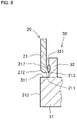
- FIG. 8 is an enlarged longitudinal sectional view of a first cap 30 including a first protrusion 32 received in a first end portion 21 of a cylinder 20 in a piezoelectric actuator 10 according to the present embodiment.
- FIG. 9 is an enlarged longitudinal sectional view of a modification of the piezoelectric actuator 10 shown in FIG. 8 .
- the piezoelectric actuator 10 may include a case 2 including a metal joint 217 located between an inner peripheral surface 213 of the first end portion 21 and an outer peripheral surface 321 of the first protrusion 32.
- the case 2 including the metal joint 217 distributes, across the outer peripheral surface of the metal joint 217, stress resulting from expansion of a piezoelectric element 1 and concentrating at the joint between the first end portion 21 and the first protrusion 32.
- the structure reduces linear development of microcracks and is thus less likely to degrade the sealing under stress concentration at an edge 211 of the first end portion 21.
- the first end portion 21 may have an outer peripheral surface 212 curved across the entire circumference to relax stress more effectively.
- the metal joint 217 has a different crystal structure from the first cap 30 and the cylinder 20.
- the metal joint 217 may be formed by, for example, counterdiffusion of the components of the first cap 30 and the cylinder 20.
- the metal joint 217 may be formed by diffusion of the metal contained in the first cap 30 into the cylinder 20, or diffusion of the metal contained in the cylinder 20 into the first cap 30.
- the metal joint 217 may be formed by, for example, melting the inner peripheral surface 213 of the first end portion 21 and the outer peripheral surface 321 of the first protrusion 32 with laser irradiation for welding the first cap 30 and the cylinder 20.
- the metal joint 217 may contain, for example, the components of the first cap 30 and the cylinder 20.
- the metal joint 217 may have any cross-sectional shape, such as circular, elliptic, or oval.
- the metal joint 217 may extend entirely or partially across the inner peripheral surface 212 of the first end portion 21.
- the metal joint 217 and its shape may be detected by structural analysis using, for example, an electron probe microanalyzer (EPMA).
- EPMA electron probe microanalyzer
- the metal joint 217 may extend to the edge 211 of the first end portion 21.
- the structure reduces microcracks developing from the edge 211 of the first end portion 21 under stress concentrating at the edge 211. The structure thus relaxes stress more effectively and is less likely to degrade the sealing.
- the metal joint 217 may be located on the outer peripheral surface of the first end portion 21.
- the case 2 includes the metal joint 217 located between the first end portion 21 and the first protrusion 32.
- the case 2 may include a metal joint 217 located between an inner peripheral surface 224 of a second end portion 22 and an outer peripheral surface 421 of a second protrusion 42.
- the case 2 may include the metal joint 217 located between the first end portion 21 and the first protrusion 32, and the metal joint 217 located between the second end portion 22 and the second protrusion 42.
- the piezoelectric actuator 10 according to the present embodiment effectively distributes stress between the cylinder 20 and at least either the first cap 30 or a second cap 40 when the piezoelectric element 1 expands.
- the structure reduces development of microcracks at the joint between the cylinder 20 and at least either the first cap 30 or the second cap 40 and is less likely to degrade the sealing.
- the piezoelectric actuator according to one or more embodiments of the present disclosure may include any piezoelectric element other than a multilayer piezoelectric element described above.
Landscapes
- General Electrical Machinery Utilizing Piezoelectricity, Electrostriction Or Magnetostriction (AREA)
Abstract
Description
- The present disclosure relates to a piezoelectric actuator.
- A known encapsulated multilayer piezoelectric actuator includes a multilayer piezoelectric element accommodated in an expandable metal case. The multilayer piezoelectric element includes a stack of alternate piezoelectric ceramic layers and internal electrode layers. The metal case includes a hollow member to allow communication between inside and outside. The hollow member is sealed with upper and lower caps to block communication between inside and outside the metal case (refer to, for example, Patent Literature 1).
- In the known piezoelectric actuator, the expandable hollow member is joined to the upper and lower caps and thus expands in response to expansion of the piezoelectric element. This structure is likely to cause stress concentration at joints between the hollow member and the upper and lower caps, possibly degrading the sealing of the hollow member. Thus, the known piezoelectric actuator is to be more durable.
- Patent Literature 1:
Japanese Unexamined Patent Application Publication No. 2010-192832 - A piezoelectric actuator according to one or more aspects of the present disclosure includes a piezoelectric element, and a case accommodating the piezoelectric element. The case is deformable to conform with expansion or contraction of the piezoelectric element. The case includes a cylinder including a first end portion being open, and a first cap including a first end plate being circular and a first protrusion being annular. The first protrusion is located on a first surface of the first end plate and protrudes perpendicularly to the first surface. The cylinder includes the first end portion receiving the first protrusion on the first cap. The first end portion includes an inner peripheral surface joined to an outer peripheral surface of the first protrusion. The first end portion includes an edge located nearer an edge of the first protrusion than the first surface of the first end plate in an axial direction of the cylinder.
- The objects, features, and advantages of the present invention will become more apparent from the following detailed description and the drawings.
-
FIG. 1 is a schematic perspective view of a piezoelectric actuator according to a first embodiment of the present disclosure. -
FIG. 2 is a schematic longitudinal sectional view of the piezoelectric actuator taken along line A-A inFIG. 1 . -
FIG. 3 is an enlarged longitudinal sectional view of a first cap in the piezoelectric actuator according to the first embodiment of the present disclosure. -
FIG. 4 is an enlarged longitudinal sectional view of the first cap received in a cylinder in the piezoelectric actuator according to the first embodiment of the present disclosure. -
FIG. 5 is an enlarged longitudinal sectional view of a first cap received in a cylinder in a piezoelectric actuator according to a second embodiment of the present disclosure. -
FIG. 6 is an enlarged longitudinal sectional view of a first cap received in a cylinder in a piezoelectric actuator according to a third embodiment of the present disclosure. -
FIG. 7 is an enlarged longitudinal sectional view of the first cap in the piezoelectric actuator according to the second embodiment of the present disclosure received in the cylinder in the third embodiment. -
FIG. 8 is an enlarged longitudinal sectional view of a first cap received in a cylinder in a piezoelectric actuator according to a fourth embodiment of the present disclosure. -
FIG. 9 is an enlarged longitudinal sectional view of a modification of the piezoelectric actuator shown inFIG. 8 . - A piezoelectric actuator according to a first embodiment of the present disclosure will now be described with reference to the drawings.
FIG. 1 is a schematic perspective view of apiezoelectric actuator 10 according to the first embodiment.FIG. 2 is a schematic longitudinal sectional view of thepiezoelectric actuator 10 taken along line A-A inFIG. 1 .FIG. 3 is an enlarged longitudinal sectional view of afirst cap 30 in thepiezoelectric actuator 10.FIG. 4 is an enlarged longitudinal sectional view of thefirst cap 30 received in acylinder 20 in thepiezoelectric actuator 10. The invention is not limited to one or more embodiments described below. - The
piezoelectric actuator 10 shown inFIGs. 1 to 4 includes apiezoelectric element 1 and acase 2. Thecase 2 accommodates thepiezoelectric element 1. Thecase 2 includes thecylinder 20, thefirst cap 30, and asecond cap 40. - The
piezoelectric element 1 included in thepiezoelectric actuator 10 is, for example, a multilayer piezoelectric element. As shown inFIG. 2 , thepiezoelectric element 1 includes a stack including, for example, an active portion in which piezoelectric layers and internal electrode layers are alternately stacked and an inactive portion in which piezoelectric layers are stacked on both ends of the active portion in the stacking direction. In the active portion, the piezoelectric layers expand or contract in the stacking direction upon being driven. In the inactive portion, the piezoelectric layers do not expand or contract in the stacking direction upon being driven. - The stack in the
piezoelectric element 1 is, for example, a rectangular prism having a length of about 4 to 7 mm, a width of about 4 to 7 mm, and a height of about 20 to 50 mm. The stack may be, for example, a hexagonal prism or an octagonal prism. - The piezoelectric layers in the stack are formed from a piezoelectric ceramic with piezoelectric properties. The piezoelectric ceramic may contain a powder with a mean particle size of, for example, 1.6 to 2.8 µm. Examples of the piezoelectric ceramic include perovskite oxides, such as lead zirconate titanate (PbZrO3-PbTiO3), lithium niobate (LiNbO3), and lithium tantalate (LiTaO3).
- The internal electrode layers in the stack may mainly contain a metal such as silver, a silver-palladium alloy, a silver-platinum alloy, or copper. The internal electrode layers include, for example, positive electrodes and negative electrodes alternately located in the stacking direction. The positive electrodes extend to one side surface of the stack. The negative electrodes extend to another side surface of the stack. In the active portion with this structure, a driving voltage can be applied to a piezoelectric layer between adjacent internal electrode layers in the stacking direction. The stack may also include metal layers for stress relaxation that do not serve as internal electrode layers.
- The stack has a pair of opposing side surfaces covered with external electrodes. The positive or negative electrodes (or a ground electrode) included in the internal electrode layers extend to these side surfaces for electrical connection to the external electrodes. The external electrodes may be, for example, metallized layers containing silver and glass.
- The stack has another pair of opposing side surfaces at which the positive and negative electrodes (or the ground electrode) included in the internal electrode layers are exposed. These side surfaces may be covered with an insulating coating as appropriate. The coating may reduce creeping discharge between the positive and negative electrodes under a high voltage applied for driving. The insulating coating may be, for example, a ceramic material. To avoid creeping discharge resulting from peeling of the coating, the ceramic material may be deformable under stress to conform with the deformation (e.g., expansion or contraction) of the stack when the piezoelectric actuator is driven.
- Examples of the coating material include partially stabilized zirconia that locally undergoes phase transformation under stress to change volume and deform, a ceramic material such as Ln1-xSixAlO3+0.5x (where Ln is at least one selected from the group consisting of Sn, Y, La, Ce, Pr, Nd, Pm, Sm, Eu, Gd, Tb, Dy, Ho, Er, Tm, and Yb, and x = 0.01 to 0.3), or a piezoelectric material that undergoes a change in the interionic distance in the crystal lattice to relax any stress, such as barium titanate or lead zirconate titanate. The coating is formed by, for example, applying ink containing any of the ceramic and piezoelectric materials listed above onto the side surfaces of the stack by dipping or screen printing, and then sintering the ink.
- The
case 2 in thepiezoelectric actuator 10 accommodates thepiezoelectric element 1. Thepiezoelectric element 1 has a lower end face in contact with the upper face of thefirst cap 30, and an upper end face in contact with the lower face of thesecond cap 40. - The
cylinder 20 vertically extends and is open at both ends. Thecylinder 20 is, for example, a seamless tube prepared in a predetermined shape. The seamless tube is then shaped into a bellows by rolling or isostatic pressing. Thecylinder 20 has a predetermined spring constant to conform with the expansion and contraction of thepiezoelectric element 1 under a voltage applied to thepiezoelectric element 1. Thecylinder 20 may have a spring constant adjusted in accordance with the thickness of thecylinder 20 or the number or the shape of grooves on thecylinder 20. Thecylinder 20 may have a thickness of, for example, 0.1 to 0.5 mm. - As shown in
FIG. 3 , thefirst cap 30 includes a circularfirst end plate 31 and an annularfirst protrusion 32. Thefirst protrusion 32 is located on afirst surface 311 of thefirst end plate 31 and protrudes perpendicularly to thefirst surface 311. - As shown in
FIG. 4 , thefirst cap 30 has an outer diameter substantially the same as the inner diameter of the opening in afirst end portion 21 of thecylinder 20. Thefirst cap 30 is fitted in thecylinder 20 through the opening in thefirst end portion 21 to have thefirst protrusion 32 received in thefirst end portion 21 of thecylinder 20. Thefirst end portion 21 of thecylinder 20 has an innerperipheral surface 213 joined to an outerperipheral surface 321 of thefirst protrusion 32 on thefirst cap 30. Thefirst end portion 21 has an edge (or an open end) 211 located nearer the edge of thefirst protrusion 32 than thefirst surface 311 of thefirst end plate 31 in the axial direction of thecylinder 20. The innerperipheral surface 213 of thefirst end portion 21 may be joined to the outerperipheral surface 321 of thefirst protrusion 32 by, for example, laser welding or resistance welding. - The
first end portion 21 has theedge 211 located nearer the edge of thefirst protrusion 32 than thefirst surface 311 of thefirst end plate 31 to reduce stress concentration at the clearance between thecylinder 20 and thefirst cap 30 when thepiezoelectric element 1 expands. This reduces deformation of the outer periphery of the first cap and is thus less likely to degrade the sealing. - The
first cap 30 may have acorner 313 between an outerperipheral surface 312 and thefirst surface 311 of thefirst end plate 31. Thefirst cap 30 may have acorner 322 between the outerperipheral surface 321 of thefirst protrusion 32 and thefirst surface 311 of thefirst end plate 31. - The
corners first cap 30 receive stress. This structure thus distributes and relaxes stress concentrating on other parts in a known structure. - The
first end portion 21 may have an outerperipheral surface 212 curved across the entire circumference as in the present embodiment. This structure reduces stress concentration at the joint between thecylinder 20 and thefirst protrusion 32. The curved peripheral surface can change its curvature and distributes stress resulting from expansion of thepiezoelectric element 1. - As shown in
FIG. 2 , thesecond cap 40 includes a circularsecond end plate 41 and an annularsecond protrusion 42. Thesecond protrusion 42 is located on athird surface 411 of thesecond end plate 41. Thecylinder 20 has an opensecond end portion 22 opposite to thefirst end portion 21. Thecylinder 20 has thesecond end portion 22 receiving thesecond protrusion 42 on thesecond cap 40. Thesecond end portion 22 has an innerperipheral surface 224 joined to an outerperipheral surface 421 of thesecond protrusion 42. Thesecond end portion 22 has anend face 222 spaced from thethird surface 411 of thesecond end plate 41. The innerperipheral surface 224 of thesecond end portion 22 may be joined to the outerperipheral surface 421 of thesecond protrusion 42 by, for example, laser welding or resistance welding. - The
piezoelectric actuator 10 with this structure according to the present embodiment reduces stress concentration at the joint between the innerperipheral surface 224 of thesecond end portion 22 and the outerperipheral surface 421 of thesecond protrusion 42. The structure also more efficiently distributes stress resulting from expansion of thepiezoelectric element 1 than a structure with thecase 2 including thefirst cap 30 alone. - The
cylinder 20, thefirst cap 30, and thesecond cap 40 may be formed from a metal such as SUS304 or SUS316L. - The
first end plate 31 may have through-holes 315 extending from thefirst surface 311 to asecond surface 314 opposite to thefirst surface 311. The through-holes 315 may receivelead pins 50 electrically connected to thepiezoelectric element 1. - A piezoelectric actuator according to a second embodiment of the present disclosure will now be described with reference to the drawing.
FIG. 5 is an enlarged longitudinal sectional view of afirst cap 30 including afirst protrusion 32 received in afirst end portion 21 of acylinder 20 in apiezoelectric actuator 10 according to the present embodiment. - The
first protrusion 32 includes an annularfirst section 323 and an annularsecond section 324. Thesecond section 324 is located nearer afirst end plate 31 than thefirst section 323. Thesecond section 324 has a larger outer diameter than thefirst section 323. Thefirst end portion 21 has an innerperipheral surface 214 joined to an outerperipheral surface 321 of thefirst section 323. In the present embodiment, thefirst end portion 21 has anedge 211 spaced from anupper face 325 of thesecond section 324 of thefirst protrusion 32. This structure distributes stress across the entire circumference at the boundary with thesecond section 324 thicker than thefirst section 323 when torsional stress results from a slight difference in the expansion or contraction direction between apiezoelectric element 1 and acase 2. Thepiezoelectric actuator 10 is thus less likely to degrade the sealing after prolonged and repeated driving. - The
piezoelectric actuator 10 with this structure according to the present embodiment reduces stress concentration at the joint between the innerperipheral surface 214 of thefirst end portion 21 of thecylinder 20 and the outerperipheral surface 321 of thefirst section 323 of thefirst protrusion 32. The structure also distributes stress resulting from expansion of thepiezoelectric element 1 and reduces cracks at the joint. - A piezoelectric actuator according to a third embodiment of the present disclosure will now be described with reference to the drawings.
FIG. 6 is an enlarged longitudinal sectional view of afirst cap 30 including afirst protrusion 32 received in afirst end portion 21 of acylinder 20 in apiezoelectric actuator 10 according to the present embodiment. - The
first end portion 21 of thecylinder 20 includes afirst portion 215 having anedge 211, and asecond portion 216. Thesecond portion 216 is located inward from thefirst portion 215 in the axial direction of thecylinder 20 and has a larger inner diameter than thefirst portion 215. Thefirst portion 215 has an innerperipheral surface 214 joined to an outerperipheral surface 321 of thefirst protrusion 32. Thesecond portion 216 has an innerperipheral surface 214 spaced from the outerperipheral surface 321 of thefirst protrusion 32 in the radial direction of thecylinder 20. - The
piezoelectric actuator 10 with this structure according to the present embodiment reduces stress concentration at the joint between the innerperipheral surface 214 of thefirst portion 215 and the outerperipheral surface 321 of thefirst protrusion 32. The structure also distributes any stress resulting from expansion of apiezoelectric element 1. The structure also reduces axial wobbling of thepiezoelectric element 1, in addition to achieving stress distribution. - The
first end portion 21 in the present embodiment may replace thefirst end portion 21 in thepiezoelectric actuator 10 according to the second embodiment of the present disclosure. In this case, afirst portion 215 has an innerperipheral surface 214 joined to the outerperipheral surface 321 of thefirst section 323 as shown inFIG. 7 . - The
piezoelectric actuator 10 with this structure according to the present embodiment reduces stress concentration at the joint between the innerperipheral surface 214 of thesecond portion 216 and the outerperipheral surface 321 of thefirst section 323. The structure also distributes stress resulting from expansion of thepiezoelectric element 1. The structure also reduces axial wobbling of thepiezoelectric element 1, in addition to achieving stress distribution. - A piezoelectric actuator according to a fourth embodiment of the present disclosure will now be described with reference to the drawings.
FIG. 8 is an enlarged longitudinal sectional view of afirst cap 30 including afirst protrusion 32 received in afirst end portion 21 of acylinder 20 in apiezoelectric actuator 10 according to the present embodiment.FIG. 9 is an enlarged longitudinal sectional view of a modification of thepiezoelectric actuator 10 shown inFIG. 8 . - As shown in
FIG. 8 , thepiezoelectric actuator 10 may include acase 2 including a metal joint 217 located between an innerperipheral surface 213 of thefirst end portion 21 and an outerperipheral surface 321 of thefirst protrusion 32. Thecase 2 including themetal joint 217 distributes, across the outer peripheral surface of the metal joint 217, stress resulting from expansion of apiezoelectric element 1 and concentrating at the joint between thefirst end portion 21 and thefirst protrusion 32. The structure reduces linear development of microcracks and is thus less likely to degrade the sealing under stress concentration at anedge 211 of thefirst end portion 21. Thefirst end portion 21 may have an outerperipheral surface 212 curved across the entire circumference to relax stress more effectively. - The
metal joint 217 has a different crystal structure from thefirst cap 30 and thecylinder 20. The metal joint 217 may be formed by, for example, counterdiffusion of the components of thefirst cap 30 and thecylinder 20. The metal joint 217 may be formed by diffusion of the metal contained in thefirst cap 30 into thecylinder 20, or diffusion of the metal contained in thecylinder 20 into thefirst cap 30. The metal joint 217 may be formed by, for example, melting the innerperipheral surface 213 of thefirst end portion 21 and the outerperipheral surface 321 of thefirst protrusion 32 with laser irradiation for welding thefirst cap 30 and thecylinder 20. The metal joint 217 may contain, for example, the components of thefirst cap 30 and thecylinder 20. - The metal joint 217 may have any cross-sectional shape, such as circular, elliptic, or oval. The metal joint 217 may extend entirely or partially across the inner
peripheral surface 212 of thefirst end portion 21. Themetal joint 217 and its shape may be detected by structural analysis using, for example, an electron probe microanalyzer (EPMA). - As shown in
FIG. 9 , the metal joint 217 may extend to theedge 211 of thefirst end portion 21. The structure reduces microcracks developing from theedge 211 of thefirst end portion 21 under stress concentrating at theedge 211. The structure thus relaxes stress more effectively and is less likely to degrade the sealing. The metal joint 217 may be located on the outer peripheral surface of thefirst end portion 21. - In the examples described above, the
case 2 includes the metal joint 217 located between thefirst end portion 21 and thefirst protrusion 32. In some embodiments, thecase 2 may include a metal joint 217 located between an innerperipheral surface 224 of asecond end portion 22 and an outerperipheral surface 421 of asecond protrusion 42. In some embodiments, thecase 2 may include the metal joint 217 located between thefirst end portion 21 and thefirst protrusion 32, and the metal joint 217 located between thesecond end portion 22 and thesecond protrusion 42. Thepiezoelectric actuator 10 according to the present embodiment effectively distributes stress between thecylinder 20 and at least either thefirst cap 30 or asecond cap 40 when thepiezoelectric element 1 expands. The structure reduces development of microcracks at the joint between thecylinder 20 and at least either thefirst cap 30 or thesecond cap 40 and is less likely to degrade the sealing. - The piezoelectric actuator according to one or more embodiments of the present disclosure may include any piezoelectric element other than a multilayer piezoelectric element described above.
-
- 1
- piezoelectric element
- 2
- case
- 10
- piezoelectric actuator
- 20
- cylinder
- 21
- first end portion
- 211
- edge
- 22
- second end portion
- 222
- end face
- 224
- inner peripheral surface
- 212, 312, 321
- outer peripheral surface
- 213,214
- inner peripheral surface
- 215
- first portion
- 216
- second portion
- 217
- metal joint
- 30
- first cap
- 31
- first end plate
- 32
- first protrusion
- 311
- first surface
- 312
- outer peripheral surface
- 313
- corner
- 314
- second surface
- 315
- through-hole
- 321
- outer peripheral surface
- 322
- corner
- 323
- first section
- 324
- second section
- 325
- upper face
- 40
- second cap
- 41
- second end plate
- 42
- second protrusion
- 411
- third surface
- 421
- outer peripheral surface
- 50
- lead pin
Claims (11)
- A piezoelectric actuator, comprising:a piezoelectric element; anda case accommodating the piezoelectric element, the case being deformable to conform with expansion or contraction of the piezoelectric element, the case includinga cylinder including a first end portion being open, anda first cap including a first end plate being circular and a first protrusion being annular, the first protrusion being located on a first surface of the first end plate and protruding perpendicularly to the first surface,wherein the cylinder includes the first end portion receiving the first protrusion on the first cap, the first end portion includes an inner peripheral surface joined to an outer peripheral surface of the first protrusion, and the first end portion includes an edge located nearer an edge of the first protrusion than the first surface of the first end plate in an axial direction of the cylinder.
- The piezoelectric actuator according to claim 1, wherein
the first cap has a corner joining an outer peripheral surface of the first end plate and the first surface. - The piezoelectric actuator according to claim 1 or claim 2, wherein
the first cap includes a corner joining the outer peripheral surface of the first protrusion and the first surface. - The piezoelectric actuator according to any one of claims 1 to 3, wherein
the first end portion includes a curved outer peripheral surface. - The piezoelectric actuator according to any one of claims 1 to 4, wherein
the case further includes a metal joint located between the inner peripheral surface of the first end portion and the outer peripheral surface of the first protrusion. - The piezoelectric actuator according to any one of claims 1 to 5, whereinthe first protrusion includes a first section being annular and a second section being annular, and the second section is located nearer the first end plate than the first section and has a larger outer diameter than the first section, andthe first end portion includes the inner peripheral surface joined to an outer peripheral surface of the first section.
- The piezoelectric actuator according to claim 6, wherein
the first end portion includes an end face spaced from an upper face of the second section of the first protrusion. - The piezoelectric actuator according to any one of claims 1 to 7, whereinthe cylinder includes the first end portion includinga first portion including the end face, anda second portion located inward from the first portion in the axial direction of the cylinder and having a larger inner diameter than the first portion,the first portion includes an inner peripheral surface joined to the outer peripheral surface of the first protrusion, andthe second portion includes an inner peripheral surface spaced from the outer peripheral surface of the first protrusion in a radial direction of the cylinder.
- The piezoelectric actuator according to claim 8 depending from claim 7, wherein
the second portion includes the inner peripheral surface joined to the outer peripheral surface of the first section. - The piezoelectric actuator according to any one of claims 1 to 9, wherein
the first end plate has a through-hole extending from the first surface to a second surface opposite to the first surface, and the through-hole receives a lead pin electrically connected to the piezoelectric element. - The piezoelectric actuator according to any one of claims 1 to 10, whereinthe case further includes a second cap includinga second end plate being circular, anda second protrusion being annular and located on a third surface of the second end plate,the cylinder includes a second end portion opposite to the first end portion, and the second end portion is open, andthe cylinder includes the second end portion receiving the second protrusion on the second cap, the second end portion includes an inner peripheral surface joined to an outer peripheral surface of the second protrusion, and the second end portion includes an end face spaced from the third surface of the second end plate.
Applications Claiming Priority (2)
| Application Number | Priority Date | Filing Date | Title |
|---|---|---|---|
| JP2019161546 | 2019-09-04 | ||
| PCT/JP2020/027725 WO2021044744A1 (en) | 2019-09-04 | 2020-07-16 | Piezoelectric actuator |
Publications (3)
| Publication Number | Publication Date |
|---|---|
| EP4027398A1 true EP4027398A1 (en) | 2022-07-13 |
| EP4027398A4 EP4027398A4 (en) | 2023-09-20 |
| EP4027398B1 EP4027398B1 (en) | 2025-11-12 |
Family
ID=74852390
Family Applications (1)
| Application Number | Title | Priority Date | Filing Date |
|---|---|---|---|
| EP20860274.8A Active EP4027398B1 (en) | 2019-09-04 | 2020-07-16 | Piezoelectric actuator |
Country Status (5)
| Country | Link |
|---|---|
| US (1) | US12389802B2 (en) |
| EP (1) | EP4027398B1 (en) |
| JP (1) | JP7354264B2 (en) |
| CN (1) | CN113994491B (en) |
| WO (1) | WO2021044744A1 (en) |
Families Citing this family (1)
| Publication number | Priority date | Publication date | Assignee | Title |
|---|---|---|---|---|
| US11867068B2 (en) * | 2022-05-09 | 2024-01-09 | General Electric Company | Fast response active clearance systems with piezoelectric actuator in axial, axial/radial combined, and circumferential directions |
Family Cites Families (13)
| Publication number | Priority date | Publication date | Assignee | Title |
|---|---|---|---|---|
| US5113108A (en) * | 1988-11-04 | 1992-05-12 | Nec Corporation | Hermetically sealed electrostrictive actuator |
| JPH03248581A (en) * | 1990-02-27 | 1991-11-06 | Nec Corp | electrostrictive effect element |
| JP4841048B2 (en) * | 2001-03-29 | 2011-12-21 | 京セラ株式会社 | Actuator and injection device |
| JP2003037983A (en) * | 2001-07-26 | 2003-02-07 | Nec Tokin Ceramics Corp | Displacement inversion type actuator device |
| US7429815B2 (en) * | 2006-06-23 | 2008-09-30 | Caterpillar Inc. | Fuel injector having encased piezo electric actuator |
| DE102006049884A1 (en) * | 2006-10-23 | 2008-04-30 | Robert Bosch Gmbh | Fuel injector with piezo actuator |
| ATE517440T1 (en) * | 2007-03-14 | 2011-08-15 | Delphi Tech Holding Sarl | REDUCTION OF VOLTAGE GRADIENTS WITH PIEZOELECTRIC ACTUATORS |
| JP5167031B2 (en) * | 2008-08-26 | 2013-03-21 | 中央精機株式会社 | Piezoelectric actuator |
| JP2010192832A (en) | 2009-02-20 | 2010-09-02 | Nec Tokin Corp | Case sealed type laminated piezoelectric actuator |
| DE102012223934B4 (en) * | 2012-12-20 | 2015-10-15 | Continental Automotive Gmbh | piezoinjector |
| JP2014202316A (en) * | 2013-04-08 | 2014-10-27 | 本田技研工業株式会社 | Attenuation force variable damper |
| WO2017199668A1 (en) * | 2016-05-16 | 2017-11-23 | 京セラ株式会社 | Piezoelectric actuator |
| JP6809818B2 (en) * | 2016-06-20 | 2021-01-06 | 京セラ株式会社 | Piezoelectric actuator |
-
2020
- 2020-07-16 WO PCT/JP2020/027725 patent/WO2021044744A1/en not_active Ceased
- 2020-07-16 JP JP2021543644A patent/JP7354264B2/en active Active
- 2020-07-16 CN CN202080041115.9A patent/CN113994491B/en active Active
- 2020-07-16 US US17/629,972 patent/US12389802B2/en active Active
- 2020-07-16 EP EP20860274.8A patent/EP4027398B1/en active Active
Also Published As
| Publication number | Publication date |
|---|---|
| EP4027398B1 (en) | 2025-11-12 |
| JP7354264B2 (en) | 2023-10-02 |
| EP4027398A4 (en) | 2023-09-20 |
| US20220254981A1 (en) | 2022-08-11 |
| JPWO2021044744A1 (en) | 2021-03-11 |
| CN113994491B (en) | 2025-11-04 |
| WO2021044744A1 (en) | 2021-03-11 |
| CN113994491A (en) | 2022-01-28 |
| US12389802B2 (en) | 2025-08-12 |
Similar Documents
| Publication | Publication Date | Title |
|---|---|---|
| EP0485995B1 (en) | Laminated piezoelectric actuator | |
| US5233256A (en) | Method of driving piezoelectric bimorph device and piezoelectric bimorph device | |
| EP2610934B1 (en) | Piezoelectric actuator | |
| US12389802B2 (en) | Piezoelectric actuator | |
| JPH11112046A (en) | Piezoelectric actuator and method of manufacturing the same | |
| JP6711908B2 (en) | Piezoelectric actuator | |
| JP2015106569A (en) | Piezoelectric actuator and mass flow controller including the same | |
| EP4075527B1 (en) | Piezoelectric actuator | |
| JP6809822B2 (en) | Piezoelectric actuator | |
| EP4224542A1 (en) | Piezoelectric actuator | |
| JP6144577B2 (en) | Piezoelectric actuator | |
| JP7528240B2 (en) | Piezoelectric Actuator | |
| JP7129478B2 (en) | piezoelectric actuator | |
| JP6809818B2 (en) | Piezoelectric actuator | |
| JPH04365384A (en) | mechanical amplification mechanism | |
| JP5832338B2 (en) | Piezoelectric actuator | |
| JP6809845B2 (en) | Piezoelectric actuator | |
| JPH02125674A (en) | Electrostrictive element | |
| JP6818466B2 (en) | Piezoelectric actuator | |
| WO2025094830A1 (en) | Piezoelectric element, piezoelectric actuator, and mass flow controller | |
| JPWO2013065710A1 (en) | Piezoelectric actuator | |
| JP6542660B2 (en) | Piezoelectric element, method of manufacturing the same, and piezoelectric actuator |
Legal Events
| Date | Code | Title | Description |
|---|---|---|---|
| STAA | Information on the status of an ep patent application or granted ep patent |
Free format text: STATUS: THE INTERNATIONAL PUBLICATION HAS BEEN MADE |
|
| PUAI | Public reference made under article 153(3) epc to a published international application that has entered the european phase |
Free format text: ORIGINAL CODE: 0009012 |
|
| STAA | Information on the status of an ep patent application or granted ep patent |
Free format text: STATUS: REQUEST FOR EXAMINATION WAS MADE |
|
| 17P | Request for examination filed |
Effective date: 20211025 |
|
| AK | Designated contracting states |
Kind code of ref document: A1 Designated state(s): AL AT BE BG CH CY CZ DE DK EE ES FI FR GB GR HR HU IE IS IT LI LT LU LV MC MK MT NL NO PL PT RO RS SE SI SK SM TR |
|
| DAV | Request for validation of the european patent (deleted) | ||
| DAX | Request for extension of the european patent (deleted) | ||
| P01 | Opt-out of the competence of the unified patent court (upc) registered |
Effective date: 20230505 |
|
| REG | Reference to a national code |
Ref country code: DE Ref legal event code: R079 Free format text: PREVIOUS MAIN CLASS: H01L0041047000 Ipc: H10N0030880000 Ref country code: DE Ref legal event code: R079 Ref document number: 602020062230 Country of ref document: DE Free format text: PREVIOUS MAIN CLASS: H01L0041047000 Ipc: H10N0030880000 |
|
| A4 | Supplementary search report drawn up and despatched |
Effective date: 20230823 |
|
| RIC1 | Information provided on ipc code assigned before grant |
Ipc: H10N 30/50 20230101ALI20230817BHEP Ipc: H10N 30/88 20230101AFI20230817BHEP |
|
| GRAP | Despatch of communication of intention to grant a patent |
Free format text: ORIGINAL CODE: EPIDOSNIGR1 |
|
| STAA | Information on the status of an ep patent application or granted ep patent |
Free format text: STATUS: GRANT OF PATENT IS INTENDED |
|
| INTG | Intention to grant announced |
Effective date: 20250605 |
|
| GRAS | Grant fee paid |
Free format text: ORIGINAL CODE: EPIDOSNIGR3 |
|
| GRAA | (expected) grant |
Free format text: ORIGINAL CODE: 0009210 |
|
| STAA | Information on the status of an ep patent application or granted ep patent |
Free format text: STATUS: THE PATENT HAS BEEN GRANTED |
|
| AK | Designated contracting states |
Kind code of ref document: B1 Designated state(s): AL AT BE BG CH CY CZ DE DK EE ES FI FR GB GR HR HU IE IS IT LI LT LU LV MC MK MT NL NO PL PT RO RS SE SI SK SM TR |
|
| REG | Reference to a national code |
Ref country code: CH Ref legal event code: F10 Free format text: ST27 STATUS EVENT CODE: U-0-0-F10-F00 (AS PROVIDED BY THE NATIONAL OFFICE) Effective date: 20251112 Ref country code: GB Ref legal event code: FG4D |
|
| REG | Reference to a national code |
Ref country code: DE Ref legal event code: R096 Ref document number: 602020062230 Country of ref document: DE |
|
| REG | Reference to a national code |
Ref country code: IE Ref legal event code: FG4D |
|
| REG | Reference to a national code |
Ref country code: NL Ref legal event code: MP Effective date: 20251112 |
|
| PG25 | Lapsed in a contracting state [announced via postgrant information from national office to epo] |
Ref country code: ES Free format text: LAPSE BECAUSE OF FAILURE TO SUBMIT A TRANSLATION OF THE DESCRIPTION OR TO PAY THE FEE WITHIN THE PRESCRIBED TIME-LIMIT Effective date: 20251112 |
|
| REG | Reference to a national code |
Ref country code: LT Ref legal event code: MG9D |
|
| PG25 | Lapsed in a contracting state [announced via postgrant information from national office to epo] |
Ref country code: NO Free format text: LAPSE BECAUSE OF FAILURE TO SUBMIT A TRANSLATION OF THE DESCRIPTION OR TO PAY THE FEE WITHIN THE PRESCRIBED TIME-LIMIT Effective date: 20260212 |
|
| PG25 | Lapsed in a contracting state [announced via postgrant information from national office to epo] |
Ref country code: HR Free format text: LAPSE BECAUSE OF FAILURE TO SUBMIT A TRANSLATION OF THE DESCRIPTION OR TO PAY THE FEE WITHIN THE PRESCRIBED TIME-LIMIT Effective date: 20251112 Ref country code: AT Free format text: LAPSE BECAUSE OF FAILURE TO SUBMIT A TRANSLATION OF THE DESCRIPTION OR TO PAY THE FEE WITHIN THE PRESCRIBED TIME-LIMIT Effective date: 20251112 Ref country code: FI Free format text: LAPSE BECAUSE OF FAILURE TO SUBMIT A TRANSLATION OF THE DESCRIPTION OR TO PAY THE FEE WITHIN THE PRESCRIBED TIME-LIMIT Effective date: 20251112 |
|
| REG | Reference to a national code |
Ref country code: AT Ref legal event code: MK05 Ref document number: 1857967 Country of ref document: AT Kind code of ref document: T Effective date: 20251112 |
|
| PG25 | Lapsed in a contracting state [announced via postgrant information from national office to epo] |
Ref country code: NL Free format text: LAPSE BECAUSE OF FAILURE TO SUBMIT A TRANSLATION OF THE DESCRIPTION OR TO PAY THE FEE WITHIN THE PRESCRIBED TIME-LIMIT Effective date: 20251112 |
|
| PG25 | Lapsed in a contracting state [announced via postgrant information from national office to epo] |
Ref country code: RS Free format text: LAPSE BECAUSE OF FAILURE TO SUBMIT A TRANSLATION OF THE DESCRIPTION OR TO PAY THE FEE WITHIN THE PRESCRIBED TIME-LIMIT Effective date: 20260212 |
|
| PG25 | Lapsed in a contracting state [announced via postgrant information from national office to epo] |
Ref country code: IS Free format text: LAPSE BECAUSE OF FAILURE TO SUBMIT A TRANSLATION OF THE DESCRIPTION OR TO PAY THE FEE WITHIN THE PRESCRIBED TIME-LIMIT Effective date: 20260312 |
|
| PG25 | Lapsed in a contracting state [announced via postgrant information from national office to epo] |
Ref country code: PT Free format text: LAPSE BECAUSE OF FAILURE TO SUBMIT A TRANSLATION OF THE DESCRIPTION OR TO PAY THE FEE WITHIN THE PRESCRIBED TIME-LIMIT Effective date: 20260312 |
|
| PG25 | Lapsed in a contracting state [announced via postgrant information from national office to epo] |
Ref country code: PL Free format text: LAPSE BECAUSE OF FAILURE TO SUBMIT A TRANSLATION OF THE DESCRIPTION OR TO PAY THE FEE WITHIN THE PRESCRIBED TIME-LIMIT Effective date: 20251112 |
|
| PG25 | Lapsed in a contracting state [announced via postgrant information from national office to epo] |
Ref country code: LV Free format text: LAPSE BECAUSE OF FAILURE TO SUBMIT A TRANSLATION OF THE DESCRIPTION OR TO PAY THE FEE WITHIN THE PRESCRIBED TIME-LIMIT Effective date: 20251112 |
|
| PG25 | Lapsed in a contracting state [announced via postgrant information from national office to epo] |
Ref country code: BG Free format text: LAPSE BECAUSE OF FAILURE TO SUBMIT A TRANSLATION OF THE DESCRIPTION OR TO PAY THE FEE WITHIN THE PRESCRIBED TIME-LIMIT Effective date: 20251112 |