EP4027369A1 - Charged particle beam apparatus - Google Patents
Charged particle beam apparatus Download PDFInfo
- Publication number
- EP4027369A1 EP4027369A1 EP21217377.7A EP21217377A EP4027369A1 EP 4027369 A1 EP4027369 A1 EP 4027369A1 EP 21217377 A EP21217377 A EP 21217377A EP 4027369 A1 EP4027369 A1 EP 4027369A1
- Authority
- EP
- European Patent Office
- Prior art keywords
- angle information
- tilt
- specimen
- detection solid
- detection
- Prior art date
- Legal status (The legal status is an assumption and is not a legal conclusion. Google has not performed a legal analysis and makes no representation as to the accuracy of the status listed.)
- Withdrawn
Links
Images








Classifications
-
- H—ELECTRICITY
- H01—ELECTRIC ELEMENTS
- H01J—ELECTRIC DISCHARGE TUBES OR DISCHARGE LAMPS
- H01J37/00—Discharge tubes with provision for introducing objects or material to be exposed to the discharge, e.g. for the purpose of examination or processing thereof
- H01J37/26—Electron or ion microscopes; Electron or ion diffraction tubes
- H01J37/261—Details
- H01J37/265—Controlling the tube; circuit arrangements adapted to a particular application not otherwise provided, e.g. bright-field-dark-field illumination
-
- H—ELECTRICITY
- H01—ELECTRIC ELEMENTS
- H01J—ELECTRIC DISCHARGE TUBES OR DISCHARGE LAMPS
- H01J37/00—Discharge tubes with provision for introducing objects or material to be exposed to the discharge, e.g. for the purpose of examination or processing thereof
- H01J37/26—Electron or ion microscopes; Electron or ion diffraction tubes
- H01J37/28—Electron or ion microscopes; Electron or ion diffraction tubes with scanning beams
-
- H—ELECTRICITY
- H01—ELECTRIC ELEMENTS
- H01J—ELECTRIC DISCHARGE TUBES OR DISCHARGE LAMPS
- H01J37/00—Discharge tubes with provision for introducing objects or material to be exposed to the discharge, e.g. for the purpose of examination or processing thereof
- H01J37/02—Details
- H01J37/20—Means for supporting or positioning the object or the material; Means for adjusting diaphragms or lenses associated with the support
-
- H—ELECTRICITY
- H01—ELECTRIC ELEMENTS
- H01J—ELECTRIC DISCHARGE TUBES OR DISCHARGE LAMPS
- H01J37/00—Discharge tubes with provision for introducing objects or material to be exposed to the discharge, e.g. for the purpose of examination or processing thereof
- H01J37/02—Details
- H01J37/22—Optical, image processing or photographic arrangements associated with the tube
- H01J37/226—Optical arrangements for illuminating the object; optical arrangements for collecting light from the object
- H01J37/228—Optical arrangements for illuminating the object; optical arrangements for collecting light from the object whereby illumination or light collection take place in the same area of the discharge
-
- H—ELECTRICITY
- H01—ELECTRIC ELEMENTS
- H01J—ELECTRIC DISCHARGE TUBES OR DISCHARGE LAMPS
- H01J37/00—Discharge tubes with provision for introducing objects or material to be exposed to the discharge, e.g. for the purpose of examination or processing thereof
- H01J37/02—Details
- H01J37/244—Detectors; Associated components or circuits therefor
-
- H—ELECTRICITY
- H01—ELECTRIC ELEMENTS
- H01J—ELECTRIC DISCHARGE TUBES OR DISCHARGE LAMPS
- H01J2237/00—Discharge tubes exposing object to beam, e.g. for analysis treatment, etching, imaging
- H01J2237/20—Positioning, supporting, modifying or maintaining the physical state of objects being observed or treated
- H01J2237/202—Movement
- H01J2237/20207—Tilt
-
- H—ELECTRICITY
- H01—ELECTRIC ELEMENTS
- H01J—ELECTRIC DISCHARGE TUBES OR DISCHARGE LAMPS
- H01J2237/00—Discharge tubes exposing object to beam, e.g. for analysis treatment, etching, imaging
- H01J2237/244—Detection characterized by the detecting means
- H01J2237/2441—Semiconductor detectors, e.g. diodes
- H01J2237/24415—X-ray
-
- H—ELECTRICITY
- H01—ELECTRIC ELEMENTS
- H01J—ELECTRIC DISCHARGE TUBES OR DISCHARGE LAMPS
- H01J2237/00—Discharge tubes exposing object to beam, e.g. for analysis treatment, etching, imaging
- H01J2237/244—Detection characterized by the detecting means
- H01J2237/2445—Photon detectors for X-rays, light, e.g. photomultipliers
-
- H—ELECTRICITY
- H01—ELECTRIC ELEMENTS
- H01J—ELECTRIC DISCHARGE TUBES OR DISCHARGE LAMPS
- H01J2237/00—Discharge tubes exposing object to beam, e.g. for analysis treatment, etching, imaging
- H01J2237/248—Components associated with the control of the tube
-
- H—ELECTRICITY
- H01—ELECTRIC ELEMENTS
- H01J—ELECTRIC DISCHARGE TUBES OR DISCHARGE LAMPS
- H01J2237/00—Discharge tubes exposing object to beam, e.g. for analysis treatment, etching, imaging
- H01J2237/26—Electron or ion microscopes
- H01J2237/28—Scanning microscopes
- H01J2237/2802—Transmission microscopes
-
- H—ELECTRICITY
- H01—ELECTRIC ELEMENTS
- H01J—ELECTRIC DISCHARGE TUBES OR DISCHARGE LAMPS
- H01J2237/00—Discharge tubes exposing object to beam, e.g. for analysis treatment, etching, imaging
- H01J2237/26—Electron or ion microscopes
- H01J2237/28—Scanning microscopes
- H01J2237/2803—Scanning microscopes characterised by the imaging method
- H01J2237/2808—Cathodoluminescence
Definitions
- the present invention relates to a charged particle beam apparatus.
- An energy-dispersive X-ray spectrometer is known as an elemental analyzer to be installed in a scanning electron microscope or a transmission electron microscope.
- an X-ray detector When an X-ray generated on a specimen is detected in an electron microscope including an energy-dispersive X-ray spectrometer, an X-ray detector is disposed near the specimen.
- an energy-dispersive X-ray spectrometer is disclosed in JP-A-2016-72005 .
- a specimen stage has a tilt mechanism for tilting a specimen. For example, when a crystalline specimen is observed at a high magnification in a transmission electron microscope, the specimen is tilted to observe a crystal lattice, and a specific crystal orientation is adjusted to the incident direction of an electron beam.
- an X-ray generated on the specimen may be blocked by a member disposed near the specimen of a specimen holder or the like, allowing the X-ray to reach only a part of the detection surface of an X-ray detector. This reduces the detection solid angle of the X-ray detector, resulting in low detection efficiency.
- the detection efficiency means the ratio of X-rays detected to be signals with respect to X-rays emitted from a specimen.
- the determination of the detection solid angle of a detector enables a measurement in an optimum state with high detection efficiency.
- a charged particle beam apparatus including:
- a charged particle beam apparatus including:
- the detection-solid-angle information acquisition unit acquires the detection solid-angle information from the tilt angle information with reference to the table, thereby easily determining the detection solid angle.
- a charged particle beam apparatus is a transmission electron microscope that generates X-rays by emitting electron beams to a specimen.
- the charged particle beam apparatus according to the invention may be an apparatus that generates X-rays by emitting charged particle beams (e.g., ion beams) other than electron beams to a specimen.
- the charged particle beam apparatus according to the invention may be an apparatus that generates electromagnetic waves (e.g., cathode luminescence) other than X-rays by emitting electron beams to a specimen.
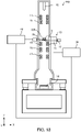
- FIG. 1 illustrates the configuration of an electron microscope 100 according to the first embodiment.
- FIG. 1 illustrates X axis, Y axis, and Z axis as three axes orthogonal to one another.
- the electron microscope 100 includes an electron source 10, illumination-system lenses 11, a specimen holder 12, a specimen stage 14, an objective lens 15, an intermediate lens 16, a projector lens 17, an imaging device 18, an X-ray detector 20, a tilt control unit 30, and a detector control unit 40.
- the electron microscope 100 is a transmission electron microscope.
- the electron source 10 generates electron beams.
- the electron source 10 is an electron gun for accelerating electrons, which are emitted from a cathode, at an anode and emitting electron beams.
- the illumination-system lenses 11 are lenses for focusing an electron beam generated by the electron source 10 and irradiating a specimen S with the electron beam.
- the specimen holder 12 holds the specimen S.
- the specimen holder 12 can be attached to the specimen stage 14.
- the specimen stage 14 positions the specimen S held by the specimen holder 12.
- the specimen stage 14 is a side-entry stage that inserts the specimen S from the side of the pole piece of the objective lens 15.
- the electron microscope 100 includes a tilt mechanism 13 for tilting the specimen S.
- the tilt mechanism 13 includes an X tilt mechanism for tilting the specimen S in X direction and a Y tilt mechanism for tilting the specimen S in Y direction.
- the specimen stage 14 includes an X tilt mechanism for tilting the specimen S in X direction.
- the specimen holder 12 includes a Y tilt mechanism for tilting the specimen S in Y direction. In this way, the specimen S can be tilted in two directions (X direction and Y direction) orthogonal to each other in the electron microscope 100.
- the configuration of the tilt mechanism 13 is not particularly limited.
- the objective lens 15 is a first-stage lens for forming a transmission-electron-microscope image (TEM image) with an electron beam having passed through the specimen S.
- the objective lens 15 has a pole piece, which is not illustrated. A magnetic field is generated between the upper pole of the pole piece and the lower pole of the pole piece and focuses an electron beam.
- the intermediate lens 16 and the projector lens 17 further enlarge the TEM image formed by the objective lens 15 and form the enlarged image on the imaging device 18.
- the objective lens 15, the intermediate lens 16, and the projector lens 17 constitute an image-forming system in the electron microscope 100.
- the imaging device 18 captures the TEM image formed by the image-forming system.
- the imaging device 18 is a digital camera, for example, a CCD (Charge Coupled Device) camera or a CMOS (Complementary MOS) camera.
- CCD Charge Coupled Device
- CMOS Complementary MOS
- the X-ray detector 20 detects a characteristic X-ray that is emitted from the specimen S by irradiating the specimen S with an electron beam.
- the X-ray detector 20 can be, for example, a silicon drift detector (SDD) or a Si (Li) detector.
- SDD silicon drift detector
- Si Si (Li) detector.
- the X-ray detector 20 is disposed near the specimen S when an X-ray is detected.
- the tilt control unit 30 controls the tilt mechanism 13.
- the tilt control unit 30 controls the X tilt mechanism of the specimen stage 14 and the Y tilt mechanism of the specimen holder 12.
- the tilt control unit 30 controls the tilt mechanism 13 to perform processing for tilting the specimen S.
- the tilt control unit 30 includes an input receiving unit for receiving an input of tilt angle information on the tilt angle of the specimen S.
- the tilt angle of the specimen S is the angle of specimen S with respect to a horizontal plane.
- the functions of the input receiving unit can be implemented by, for example, a keyboard, a mouse, a button, a touch panel, and a touch pad.
- the tilt control unit 30 sends the tilt angle information on the tilt angle of the specimen S to the detector control unit 40.
- the tilt control unit 30 sends the tilt angle information to the detector control unit 40, so that the tilt angle information can be shared by the tilt control unit 30 and the detector control unit 40.
- the tilt angle information includes information on the tilt angle of the specimen S in X direction and information on the tilt angle of the specimen S in Y direction.
- the tilt angle information is information for specifying the tilt angle of the specimen S.
- the tilt control unit 30 includes, for example, a central processing unit (CPU) and storage devices (random access memory (RAM) and read only memory (ROM)).
- CPU central processing unit
- RAM random access memory
- ROM read only memory
- programs stored in the storage device are executed by hardware such as a CPU, so that various kinds of calculation and various kinds of control are performed.
- the detector control unit 40 controls the X-ray detector 20. Moreover, the detector control unit 40 generates analysis data based on an X-ray detection result in the X-ray detector 20.
- the analysis data includes spectrum data and mapping data.
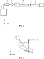
- FIG. 2 is a diagram for describing the X-ray detector 20.
- a charge is generated according to the energy of the X-ray in the X-ray detector 20.
- the charge is converted into a voltage by a field-effect transistor in the X-ray detector 20.
- a signal (pulse signal) outputted from the X-ray detector 20 is amplified by a proportional amplifier 22 and is counted for each peak value by a multichannel pulse height analyzer 24.
- the detector control unit 40 generates, based on the number of pulses for each peak value, spectrum data on spectrums indicated by X-ray energy plotted on the horizontal axis and the number of X-ray counts (intensity) plotted on the vertical axis.
- FIG. 3 is a diagram for describing a positional relationship between the X-ray detector 20 and the specimen S.
- the X-ray detector 20 is disposed on the side of the specimen S when an X-ray generated on the specimen S is detected.
- the X-ray detector 20 is disposed in -X direction when viewed from the specimen S.
- the electron microscope 100 includes the tilt mechanism 13 capable of tilting the specimen S.
- the specimen S is tilted in X direction by using the X tilt mechanism.
- an X-ray emitted from the specimen S may be blocked by a member disposed near the specimen S.
- the X-ray emitted from the specimen S is partially blocked by the specimen holder 12.
- the X-ray enters only a part of a detection surface 21 of the X-ray detector 20.
- the detection solid angle means a solid angle from the incident point of an electron beam on the specimen S to the detection surface 21 of the X-ray detector 20.
- the detection solid angle can be increased with the effective detection area of the detection surface 21. The larger the detection solid angle, the higher the detection efficiency.
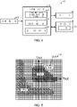
- FIG. 4 illustrates a configuration of the detector control unit 40.
- the detector control unit 40 includes a processing unit 410, an operation unit 420, a display unit 430, and a storage unit 440.
- the operation unit 420 is provided for a user input of operation information.
- the inputted operation information is outputted to the processing unit 410.
- the functions of the operation unit 420 can be implemented by hardware such as a keyboard, a mouse, a button, a touch panel, and a touch pad.
- the display unit 430 displays an image generated by the processing unit 410.
- the functions of the display unit 430 can be implemented by, for example, liquid crystal display (LCD), a cathode ray tube (CRT), and a touch panel also acting as the operation unit 420.
- LCD liquid crystal display
- CRT cathode ray tube
- touch panel also acting as the operation unit 420.
- the storage unit 440 stores programs and various kinds of data that are provided for causing a computer to act as the units of the processing unit 410.
- the storage unit 440 also acts as a work area of the processing unit 410.
- the functions of the storage unit 440 can be implemented by, for example, a hard disk and RAM.
- the processing unit 410 controls the X-ray detector 20.
- the functions of the processing unit 410 can be implemented by executing programs by means of hardware including various processors (e.g., a CPU).
- the processing unit 410 includes a detection-solid-angle information acquisition unit 412, an analysis-data generation unit 414, and a display control unit 416.
- the detection-solid-angle information acquisition unit 412 acquires tilt angle information from the tilt control unit 30 and acquires detection solid-angle information with reference to a table in which the tilt angle information and the detection solid-angle information are associated with each other.
- FIG. 5 illustrates a table T2 in which the tilt angle information and the detection solid-angle information are associated with each other.
- the horizontal axis of the table T2 in FIG. 5 indicates tilt angle information (TiltX) in X direction while the vertical axis indicates tilt angle information (TiltY) in Y direction.
- TiltX denotes the tilt angle [°] of the specimen S in X direction
- TiltY denotes the tilt angle [°] of the specimen S in Y direction.
- C[sr] is stored as detection solid-angle information.
- the detection solid-angle information C[sr] can be acquired from the tilt angle information (A,B) with reference to the table T2.
- hatching is performed at coordinates where a ratio ⁇ / ⁇ max is at least 80% and coordinates where a ratio ⁇ / ⁇ max is 40% or less where Q is a detection solid angle, and ⁇ max is a maximum detection solid angle obtained by the X-ray detector 20.
- the table T2 can be created by, for example, generating the model of the electron microscope 100 with three-dimensional CAD and calculating a detection solid angle by using the model. A detection solid angle is calculated for each of tilt angles that can be formed by the X tilt mechanism and the Y tilt mechanism, so that the table T2 can be created.
- the table T2, C[sr] is stored in the storage unit 440.
- the storage unit 440 acts as a table storage unit where the table T2 is stored.
- the analysis-data generation unit 414 generates analysis data based on an X-ray detection result in the X-ray detector 20.
- the analysis-data generation unit 414 generates, for example, spectrum data and mapping data.
- the mapping data includes element mapping data about the distribution of elements on the specimen and spectrum mapping data in which a position and a spectrum on the specimen are associated with each other.
- the analysis-data generation unit 414 stores the generated analysis data in the storage unit 440. At this point, the analysis-data generation unit 414 stores the analysis data in association with measurement conditions.
- the measurement conditions include the detection solid-angle information.
- the analysis-data generation unit 414 acquires the detection solid-angle information from the detection-solid-angle information acquisition unit 412 and stores the acquired detection solid-angle information in the storage unit 440 in association with the analysis data.
- the storage unit 440 acts as an analysis-data storage unit which stores measurement condition information in association with the analysis data.
- the single storage device acts as the analysis-data storage unit and the table storage unit.
- the analysis-data storage unit and the table storage unit may be implemented by different storage devices.
- the display control unit 416 causes the display unit 430 to display an image based on the detection solid-angle information.
- the image based on the detection solid-angle information includes numbers, symbols, figures, and graphs.
- the display control unit 416 causes the display unit 430 to display an image based on the analysis data.
- the image based on the analysis data includes spectrums and maps.
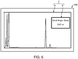
- FIG. 6 schematically illustrates an analysis screen 2.
- the display control unit 416 causes the display unit 430 to display the analysis screen 2.
- the analysis screen 2 includes an analysis-result display area 4 and a detection solid-angle display area 6.
- an image based on the analysis data is displayed.
- a spectrum is displayed as an image based on the analysis data.
- an image based on the detection solid-angle information is displayed.
- a numeric value indicating a detection solid angle is displayed as an image based on the detection solid-angle information.
- an image displayed based on the detection solid-angle information on the display unit 430 enables a user to easily determine a detection solid angle.
- the detection solid angle changes in response to a change of the tilt angle of the specimen S.
- an image for indicating a detection solid angle corresponding to the changed tilt angle is displayed on the display unit 430 in the electron microscope 100.
- the display processing that causes the display unit 430 to display an image for indicating a detection solid angle will be described below.
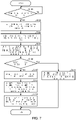
- FIG. 7 is a flowchart illustrating an example of display processing in the electron microscope 100.
- the input receiving unit receives the tilt angle information (Yes at S 100).
- the tilt control unit 30 controls the tilt mechanism 13 based on the inputted tilt angle information (S 102).
- the tilt control unit 30 acquires tilt angle information in X direction (TiltX) and tilt angle information in Y direction (TiltY) from the tilt angle information, operates the X tilt mechanism based on the tilt angle information in X direction, and operates the Y tilt mechanism based on the tilt angle information in Y direction.
- tilt angle of the specimen S reaches a tilt angle corresponding to the inputted tilt angle information.
- the tilt control unit 30 then sends the tilt angle information to the detector control unit 40 (S 104).
- the tilt angle information on the current tilt angle of the specimen S can be shared in the tilt control unit 30 and the detector control unit 40.
- the tilt angle information may be sent before the control of the tilt mechanism 13 (S102) or concurrently with the control of the tilt mechanism 13 (S102).
- the detection-solid-angle information acquisition unit 412 acquires tilt angle information from the tilt control unit 30 and acquires detection solid-angle information with reference to the table T2 (S106).
- the analysis-data generation unit 414 determines whether the user has provided an instruction to start measurement (start instruction) (S 108). For example, when a start instruction is inputted from the operation unit 420, it is determined that the start instruction has been provided.
- start instruction an instruction to start measurement
- the analysis-data generation unit 414 generates analysis data based on an X-ray detection result in the X-ray detector 20 (S110).
- the display control unit 416 causes the display unit 430 to display an image based on the analysis data and an image based on the detection solid-angle information (S112).
- the display unit 430 displays an image indicating the analysis data and an image indicating the detection solid angle of the X-ray detector 20 during measurement.
- the analysis-data generation unit 414 stores the detection solid-angle information in the storage unit 440 in association with the analysis data (S 114).
- the display control unit 416 causes the display unit 430 to display an image based on the detection solid-angle information (S116).
- the display unit 430 displays an image indicating the current detection solid angle of the X-ray detector 20.
- the electron microscope 100 includes the storage unit 440 that stores the table T2 in which the tilt angle information on the tilt angle of the specimen S and the detection solid-angle information on the detection solid angle of the X-ray detector 20 are associated with each other, the tilt control unit 30 for controlling the tilt mechanism 13, and the detection-solid-angle information acquisition unit 412 that acquires the tilt angle information from the tilt control unit 30 and acquires the detection solid-angle information with reference to the table T2.
- the detection-solid-angle information acquisition unit 412 acquires the detection solid-angle information from the tilt angle information with reference to the table T2, thereby easily determining the detection solid angle.
- the analysis-data generation unit 414 acquires the detection solid-angle information from the detection-solid-angle information acquisition unit 412 and stores the acquired detection solid-angle information in the storage unit 440 in association with the analysis data.
- the detection solid-angle information is stored in the storage unit 440 in association with the analysis data, enabling analysis in consideration of the detection solid angle. For example, in the case of a quantitative analysis with an acquired spectrum, a detection solid angle can be taken into consideration. This can increase the quantitative accuracy.
- the electron microscope 100 includes the display control unit 416 that causes the display unit 430 to display an image based on the detection solid-angle information.
- the electron microscope 100 allows the user to easily determine the detection solid angle. Hence, even in the case of analyses on multiple specimens S, detection solid angles can be analyzed under the same conditions in the electron microscope 100.
- FIGS. 8 and 9 schematically illustrate a modification of the analysis screen 2.
- a numeric value indicating a detection solid angle in the detection solid-angle display area 6 is displayed as an image based on the detection solid-angle information.
- An image based on the detection solid-angle information is not limited thereto.
- the image based on the detection solid angle may indicate a detection solid angle as a ratio ⁇ / ⁇ max (hereinafter may be simply referred to as "ratio ⁇ / ⁇ max to a maximum detection solid angle") of a detection solid angle Q to a maximum detection solid angle ⁇ max obtained by the X-ray detector 20.
- detection solid-angle information recorded at the coordinates of the table T2 in FIG. 5 may be a ratio ⁇ / ⁇ max to a maximum detection solid angle.
- the image based on the detection solid angle may indicate a ratio ⁇ / ⁇ max to a maximum detection solid angle as a figure or a graph.
- a ratio ⁇ / ⁇ max to a maximum detection solid angle as a figure or a graph.
- only an area of a circle is filled according to the ratio ⁇ / ⁇ max to the maximum detection solid angle, thereby indicating the ratio Q/Qmax to the maximum detection solid angle.
- an area actually irradiated with an X-ray and an area not irradiated with an X-ray may be displayed on a schematic image of the detection surface 21. These areas are not illustrated. This can visually identify an area actually irradiated with an X-ray on the detection surface 21.
- the electron microscope 100 sets a measurement time based on a detection solid angle such that a signal amount is kept constant in each measurement even when the detection solid angle is changed.
- FIG. 10 illustrates a modification of the detector control unit 40.
- the processing unit 410 of the detector control unit 40 includes a measurement time setting unit 417.
- the measurement time setting unit 417 sets a measurement time based on a detection solid-angle information.
- a measurement time is a time for detecting an X-ray by the X-ray detector 20 in each measurement.
- the measurement time setting unit 417 sets a measurement time based on detection solid-angle information such that a signal amount (X-ray dosage) detected by the X-ray detector 20 is kept constant in each measurement even when multiple measurements are conducted at different detection solid angles.
- the measurement time setting unit 417 sets the measurement time at 2 ⁇ t seconds in response to a change of the ratio ⁇ / ⁇ max to the maximum detection solid angle to 50% with a measurement time set at t seconds. This can keep a constant signal amount.
- the measurement time setting unit 417 sets the measurement time at t/2 seconds in response to a change of the ratio ⁇ / ⁇ max to the maximum detection solid angle to 100% with a measurement time set at t seconds. This can keep a constant signal amount.
- FIG. 11 is a flowchart illustrating an example of processing for setting a measurement time in the electron microscope 100.
- the operation unit 420 when a user operates the operation unit 420 of the detector control unit 40 to input measurement time information for setting a measurement time, the operation unit 420 receives the measurement time information (Yes at S200). When receiving the measurement time information, the operation unit 420 sends the measurement time information to the processing unit 410. In this way, the operation unit 420 acts as an input receiving unit for receiving the measurement time information.
- the measurement time setting unit 417 acquires the measurement time information from the operation unit 420 and sets a measurement time based on the acquired measurement time information (S202).
- the tilt control unit 30 then sends tilt angle information to the detector control unit 40 (S204).
- current tilt angle information on the specimen S can be shared in the tilt control unit 30 and the detector control unit 40.
- the tilt angle information may be sent before the setting of a measurement time (S202) or concurrently with the setting of a measurement time (S202).
- the detection-solid-angle information acquisition unit 412 acquires the tilt angle information from the tilt control unit 30 and acquires detection solid-angle information with reference to the table T2 (S206).
- the measurement time setting unit 417 determines whether a detection solid angle has been changed, based on detection solid-angle information (S208). If the measurement time setting unit 417 determines that a detection solid angle is not changed (No at S208), the process returns to processing S204, and then the processing S204 for sending the tilt angle information by the tilt control unit 30 and the processing S206 for acquiring the tilt solid-angle information by the detection-solid-angle information acquisition unit 412 are performed. The measurement time setting unit 417 then determines whether a detection solid angle has been changed (S208). In this way, the measurement time setting unit 417 monitors a detection solid angle.
- a measurement time is set based on detection solid-angle information (S210).
- the measurement time setting unit 417 changes a measurement time from t seconds to 2 ⁇ seconds. For example, when a ratio to a maximum detection solid angle has changed from 50% to 100%, the measurement time setting unit 417 changes a measurement time from t seconds to t/2 seconds. After the processing S210, the electron microscope 100 terminates the processing for setting a measurement time.
- the electron microscope 100 includes the measurement time setting unit 417 that sets a measurement time for detecting an X-ray by the X-ray detector 20.
- the measurement time setting unit 417 sets a measurement time based on the detection solid-angle information.
- the electron microscope 100 can set uniform conditions for a signal amount detected by the X-ray detector 20 in each measurement even when multiple measurements are conducted at different detection solid angles.
- FIG. 12 illustrates a modification of the detector control unit 40.
- the processing unit 410 of the detector control unit 40 includes a tilt-angle information acquisition unit 418.
- the operation unit 420 When the user inputs detection solid-angle information via the operation unit 420, the operation unit 420 receives the detection solid-angle information and sends the information to the processing unit 410. In this way, the operation unit 420 acts as an input receiving unit for receiving the detection solid-angle information.
- the tilt-angle information acquisition unit 418 sends the acquired tilt angle information to the tilt control unit 30.
- the tilt control unit 30 controls the tilt mechanism 13 based on the tilt angle information. Hence, the user can perform a measurement at a desired detection solid angle.
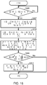
- FIG. 13 is a flowchart illustrating an example of processing for setting a detection solid angle in the electron microscope 100.
- the operation unit 420 receives the detection solid-angle information (Yes at S300).
- the operation unit 420 sends the detection solid-angle information to the processing unit 410.
- the tilt-angle information acquisition unit 418 acquires the detection solid-angle information from the operation unit 420 and acquires tilt angle information with reference to the table T2 (S302).
- the tilt-angle information acquisition unit 418 sends the acquired tilt angle information to the tilt control unit 30 (S304).
- the tilt control unit 30 controls the tilt mechanism 13 based on the tilt angle information (S306).
- the specimen S tilts, and the detection solid angle of the X-ray detector 20 reaches a detection solid angle corresponding to the inputted detection solid-angle information.
- the electron microscope 100 terminates the processing for setting a detection solid angle.
- the electron microscope 100 includes the operation unit 420 acting as an input receiving unit for receiving the input of the detection solid-angle information, and the tilt-angle information acquisition unit 418 that acquires the detection solid-angle information from the input receiving unit and acquires tilt angle information with reference to the table T2.
- the tilt control unit 30 controls the tilt mechanism 13 based on the tilt angle information.
- the electron microscope 100 can operate the tilt control unit 30 with a desired detection solid angle. This can automatically set the detection solid angle of the X-ray detector 20 to a desired detection solid angle in the electron microscope 100.
- FIG. 14 illustrates a modification of the detector control unit 40.
- the processing unit 410 of the detector control unit 40 includes a notification unit 419.
- FIG. 15 illustrates an example of a notification by the notification unit 419.
- the notification unit 419 notifies warning information when a detection solid angle is smaller than a preset threshold.
- a notification by the notification unit 419 is a message 8 for warning of a small detection solid angle.
- a notification by the notification unit 419 is not limited to the display of the message 8.
- the notification may be a notification with a beeper sound or a notification with lamplight.
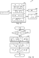
- FIG. 16 is a flowchart illustrating an example of processing for a notification in the electron microscope 100.
- the input receiving unit receives the tilt angle information (Yes at S400).
- the input receiving unit outputs the tilt angle information to the tilt control unit 30.
- the tilt control unit 30 controls the tilt mechanism 13 based on the inputted tilt angle information (S402).
- the tilt control unit 30 sends the tilt angle information to the detector control unit 40 (S404).
- the detection-solid-angle information acquisition unit 412 acquires the tilt angle information from the tilt control unit 30 and acquires detection solid-angle information with reference to the table T2 (S406).
- the notification unit 419 determines whether a detection solid angle indicated by the detection solid-angle information acquired by the detection-solid-angle information acquisition unit 412 is smaller than the preset threshold (S408). If it is determined that the detection solid angle indicated by the detection solid-angle information is smaller than the threshold (Yes at S408), the notification unit 419 notifies warning information (S410).
- the electron microscope 100 terminates the notification.
- the electron microscope 100 includes the notification unit 419, allowing a user to easily determine that a detection solid angle is small.
- FIG. 17 illustrates a modification of the detector control unit 40.
- the specimen holder 12 appears in various forms according to the purpose of observation or analysis.
- the relationship between tilt angle information and detection solid angle information changes depending upon the shape of the tip of the specimen holder 12.
- the electron microscope 100 includes a first specimen holder and a second specimen holder as the specimen holder 12.
- the first specimen holder and the second specimen holder have tips in different shapes.
- the storage unit 440 stores a table T2 (an example of a first table) and a table T4 (an example of a second table).
- table T2 tilt angle information and detection solid-angle information in the first specimen holder are associated with each other.
- table T4 tilt angle information and detection solid-angle information in the second specimen holder are associated with each other.
- the detection-solid-angle information acquisition unit 412 determines whether to use the table T2 or the table T4 based on the information.
- the information for specifying the kind of specimen holder is inputted by a user via the operation unit 420, so that the information for specifying the kind of specimen holder is sent from the operation unit 420 to the processing unit 410.
- the information for specifying the kind of specimen holder may be acquired by reception by the detection-solid-angle information acquisition unit 412, the information being outputted from the first specimen holder and the second specimen holder.
- the electron microscope 100 includes two kinds of specimen holder 12.
- the electron microscope 100 may include three or more kinds of specimen holder 12.
- the number of tables stored in the storage unit 440 increases with the number of kinds of specimen holder 12.
- FIGS. 18 and 19 illustrate configurations of an electron microscope 200 according to the second embodiment.
- the electron microscope 100 includes the single X-ray detector 20 as illustrated in FIGS. 1 and 2
- the electron microscope 200 includes a second X-ray detector 220 in addition to an X-ray detector 20 (hereinafter also referred to as "first X-ray detector 20") as illustrated in FIGS. 18 and 19 .
- the electron microscope 200 includes two X-ray detectors.
- the first X-ray detector 20 when viewed from a specimen S, the first X-ray detector 20 is disposed in -X direction, whereas the second X-ray detector 220 is disposed in +Y direction.
- a charge is generated according to the energy of the X-ray in the first X-ray detector 20.
- the charge is converted into a voltage by a field-effect transistor in the X-ray detector 20.
- a signal (pulse signal) outputted from the first X-ray detector 20 is amplified by a proportional amplifier 22.
- a charge is generated according to the energy of the X-ray in the second X-ray detector 220.
- the charge is converted into a voltage by a field-effect transistor in the second X-ray detector 220.
- a signal (pulse signal) outputted from the second X-ray detector 220 is amplified by a proportional amplifier 222.
- a pulse signal outputted from the first X-ray detector 20 and a pulse signal outputted from the second X-ray detector 220 are counted for each peak value by a multichannel pulse height analyzer 24.
- the detector control unit 40 generates, based on the number of pulses for each peak value, data on spectrums (spectrum data) indicated by X-ray energy plotted on the horizontal axis and the number of X-ray counts (intensity) plotted on the vertical axis.
- the electron microscope 200 includes the first X-ray detector 20 and the second X-ray detector 220, thereby improving the detection efficiency.
- FIG. 20 is a diagram for describing a positional relationship between the first X-ray detector 20 and the specimen S and a positional relationship between the second X-ray detector 220 and the specimen S.
- the first X-ray detector 20 and the second X-ray detector 220 are disposed on the side of the specimen S when an X-ray generated on the specimen S is detected.
- the first X-ray detector 20 and the second X-ray detector 220 are disposed at different positions.
- the detection surface 21 of the first X-ray detector 20 is directed in +X direction while a detection surface 221 of the second X-ray detector 220 is directed in -Y direction.
- the specimen S tilts in +X direction.
- the detection solid angle of the first X-ray detector 20 and the detection solid angle of the second X-ray detector 220 are different from each other. For this reason, the relationship between a tilt angle and a detection solid angle in the first X-ray detector 20 and the relationship between a tilt angle and a detection solid angle in the second X-ray detector 220 are different from each other.
- FIG. 21 is a diagram illustrating a configuration of the detector control unit 40.
- a storage unit 440 stores a table T2 (an example of a third table) in which tilt angle information and detection solid-angle information are associated with each other in the first X-ray detector 20 and a table T6 (an example of a fourth table) in which tilt angle information and detection solid-angle information are associated with each other in the second X-ray detector 220.
- the detection-solid-angle information acquisition unit 412 refers to the table T2 when acquiring the detection solid-angle information in the first X-ray detector 20 from the tilt angle information. Furthermore, the detection-solid-angle information acquisition unit 412 refers to the table T6 when acquiring the detection solid-angle information in the second X-ray detector 220 from the tilt angle information.
- the storage unit 440 stores four tables, which are not illustrated.
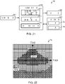
- FIG. 22 illustrates the table T6 in which tilt angle information and detection solid-angle information in the second X-ray detector 220 are associated with each other.
- the table T6 is different from the table T2 in FIG. 5 .
- the table T6 is created by the same method as the table T2.
- a display control unit 416 causes a display unit 430 to display an image based on the detection solid-angle information of the first X-ray detector 20 and an image based on the detection solid-angle information of the second X-ray detector 220.
- FIGS. 23 to 25 each schematically illustrate an analysis screen 2.
- the detection solid angle of the first X-ray detector 20, the detection solid angle of the second X-ray detector 220, and the sum of the detection solid angle of the first X-ray detector 20 and the detection solid angle of the second X-ray detector 220 may be displayed in a detection solid-angle display area 6.
- a ratio ⁇ / ⁇ max to a maximum detection solid angle in the first X-ray detector 20 may be displayed in the detection solid-angle display area 6.
- a ratio ⁇ / ⁇ max to a maximum detection solid angle in the first X-ray detector 20 and a ratio ⁇ / ⁇ max to a maximum detection solid angle in the second X-ray detector 220 may be displayed as figures or graphs in the detection solid-angle display area 6.
- the display processing in the electron microscope 200 is different from the display processing in the electron microscope 100 in FIG. 7 in that in processing S106, the electron microscope 200 refers to the table T2 when acquiring the detection solid-angle information of the first X-ray detector 20 and refers to the table T6 when acquiring the detection solid-angle information of the second X-ray detector 220.
- Other processing is similar to the display processing in the electron microscope 100 illustrated in FIG. 7 , and an explanation thereof is omitted.
- the table T2 and the table T6 are stored in the storage unit 440.
- the detection solid angle of the first X-ray detector 20 and the detection solid angle of the second X-ray detector 220 can be easily determined.
- the second to fifth modifications of the first embodiment are also applicable to the second embodiment.
- the specimen is irradiated with an electron beam to generate an X-ray on the specimen.
- a charged particle beam apparatus according to the invention may generate an X-ray on a specimen by emitting a charged particle beam (e.g., an ion beam) other than an electron beam.
- the charged particle beam apparatus may include a detector for detecting electromagnetic waves other than X-rays.
- the charged particle beam apparatus according to the invention may include a detector for detecting light (cathode luminescence) generated by irradiating a specimen with an electron beam.
- the charged particle beam apparatus may be, for example, a scanning transmission electron microscope (STEM), a scanning electron microscope (SEM), an electron probe microanalyzer (EPMA), a focused ion beam system (FIB), or a cathode luminescence microscope.
- STEM scanning transmission electron microscope
- SEM scanning electron microscope
- EPMA electron probe microanalyzer
- FIB focused ion beam system
- cathode luminescence microscope a cathode luminescence microscope.
- the invention includes configurations that are substantially the same as the configurations described in the embodiments.
- Substantially same configurations means configurations having the same functions and methods, for example.
- the invention also includes configurations in which non-essential components described in the embodiments are replaced by other components.
- the invention further includes configurations obtained by adding known art to the configurations described in the embodiments.
Landscapes
- Chemical & Material Sciences (AREA)
- Analytical Chemistry (AREA)
- Analysing Materials By The Use Of Radiation (AREA)
Abstract
Description
- The present invention relates to a charged particle beam apparatus.
- An energy-dispersive X-ray spectrometer is known as an elemental analyzer to be installed in a scanning electron microscope or a transmission electron microscope.
- When an X-ray generated on a specimen is detected in an electron microscope including an energy-dispersive X-ray spectrometer, an X-ray detector is disposed near the specimen. Such an energy-dispersive X-ray spectrometer is disclosed in
JP-A-2016-72005 - In an electron microscope, a specimen stage has a tilt mechanism for tilting a specimen. For example, when a crystalline specimen is observed at a high magnification in a transmission electron microscope, the specimen is tilted to observe a crystal lattice, and a specific crystal orientation is adjusted to the incident direction of an electron beam.
- However, when the specimen is tilted, an X-ray generated on the specimen may be blocked by a member disposed near the specimen of a specimen holder or the like, allowing the X-ray to reach only a part of the detection surface of an X-ray detector. This reduces the detection solid angle of the X-ray detector, resulting in low detection efficiency. The detection efficiency means the ratio of X-rays detected to be signals with respect to X-rays emitted from a specimen.
- In an electron microscope, the determination of the detection solid angle of a detector enables a measurement in an optimum state with high detection efficiency.
- According to an aspect of the invention, there is provided a charged particle beam apparatus including:
- a tilt mechanism that tilts a specimen;
- a detector that detects an electromagnetic wave emitted from the specimen;
- a table storage unit that stores a table in which tilt angle information on the tilt angle of the specimen and detection solid-angle information on the detection solid angle of the detector are associated with each other;
- a tilt control unit that controls the tilt mechanism; and
- a detection-solid-angle information acquisition unit that acquires the tilt angle information from the tilt control unit and acquires the detection solid-angle information with reference to the table.
-
-
FIG. 1 illustrates a configuration of an electron microscope according to the first embodiment. -
FIG. 2 is a diagram for describing an X-ray detector. -
FIG. 3 is a diagram for describing a positional relationship between an X-ray detector and a specimen. -
FIG. 4 illustrates a configuration of a detector control unit. -
FIG. 5 illustrates a table in which tilt angle information and detection solid-angle information are associated with each other. -
FIG. 6 schematically illustrates an analysis screen. -
FIG. 7 is a flowchart illustrating an example of display processing. -
FIG. 8 schematically illustrates a modification of an analysis screen. -
FIG. 9 schematically illustrates a modification of an analysis screen. -
FIG. 10 is a diagram illustrating a modification of a detector control unit. -
FIG. 11 is a flowchart illustrating an example of processing for setting a measurement time. -
FIG. 12 is a diagram illustrating a modification of a detector control unit. -
FIG. 13 is a flowchart illustrating an example of processing for setting a detection solid angle. -
FIG. 14 is a diagram illustrating a modification of a detector control unit. -
FIG. 15 illustrates an example of a notification by a notification unit. -
FIG. 16 is a flowchart illustrating an example of processing for a notification. -
FIG. 17 is a diagram illustrating a modification of a detector control unit. -
FIG. 18 illustrates a configuration of an electron microscope according to the second embodiment. -
FIG. 19 illustrates a configuration of an electron microscope according to the second embodiment. -
FIG. 20 is a diagram for describing a positional relationship between a first X-ray detector and a specimen and a positional relationship between a second X-ray detector and a specimen. -
FIG. 21 is a diagram illustrating a configuration of a detector control unit. -
FIG. 22 illustrates a table in which tilt angle information and detection solid-angle information in a second X-ray detector are associated with each other. -
FIG. 23 schematically illustrates an analysis screen. -
FIG. 24 schematically illustrates an analysis screen. -
FIG. 25 schematically illustrates an analysis screen. - According to an embodiment of the invention, there is provided a charged particle beam apparatus including:
- a tilt mechanism that tilts a specimen;
- a detector that detects an electromagnetic wave emitted from the specimen;
- a table storage unit that stores a table in which tilt angle information on the tilt angle of the specimen and detection solid-angle information on the detection solid angle of the detector are associated with each other;
- a tilt control unit that controls the tilt mechanism; and
- a detection-solid-angle information acquisition unit that acquires the tilt angle information from the tilt control unit and acquires the detection solid-angle information with reference to the table.
- In such a charged particle beam apparatus, the detection-solid-angle information acquisition unit acquires the detection solid-angle information from the tilt angle information with reference to the table, thereby easily determining the detection solid angle.
- Preferred embodiments of the invention are specifically described in detail below with reference to the drawings. It is noted that the following embodiments do not unduly limit the scope of the invention as stated in the claims. In addition, all of the components described in the following embodiments are not necessarily essential requirements of the invention.
- In the following example, a charged particle beam apparatus according to the embodiments of the invention is a transmission electron microscope that generates X-rays by emitting electron beams to a specimen. The charged particle beam apparatus according to the invention may be an apparatus that generates X-rays by emitting charged particle beams (e.g., ion beams) other than electron beams to a specimen. Alternatively, the charged particle beam apparatus according to the invention may be an apparatus that generates electromagnetic waves (e.g., cathode luminescence) other than X-rays by emitting electron beams to a specimen.
- An electron microscope according to a first embodiment will be first described below with reference to the accompanying drawings.
FIG. 1 illustrates the configuration of anelectron microscope 100 according to the first embodiment. For convenience,FIG. 1 illustrates X axis, Y axis, and Z axis as three axes orthogonal to one another. - The
electron microscope 100 includes anelectron source 10, illumination-system lenses 11, aspecimen holder 12, aspecimen stage 14, anobjective lens 15, anintermediate lens 16, aprojector lens 17, animaging device 18, anX-ray detector 20, atilt control unit 30, and adetector control unit 40. Theelectron microscope 100 is a transmission electron microscope. - The
electron source 10 generates electron beams. Theelectron source 10 is an electron gun for accelerating electrons, which are emitted from a cathode, at an anode and emitting electron beams. - The illumination-
system lenses 11 are lenses for focusing an electron beam generated by theelectron source 10 and irradiating a specimen S with the electron beam. - The
specimen holder 12 holds the specimen S. Thespecimen holder 12 can be attached to thespecimen stage 14. Thespecimen stage 14 positions the specimen S held by thespecimen holder 12. In the illustrated example, thespecimen stage 14 is a side-entry stage that inserts the specimen S from the side of the pole piece of theobjective lens 15. - The
electron microscope 100 includes atilt mechanism 13 for tilting the specimen S. Thetilt mechanism 13 includes an X tilt mechanism for tilting the specimen S in X direction and a Y tilt mechanism for tilting the specimen S in Y direction. Specifically, thespecimen stage 14 includes an X tilt mechanism for tilting the specimen S in X direction. Furthermore, thespecimen holder 12 includes a Y tilt mechanism for tilting the specimen S in Y direction. In this way, the specimen S can be tilted in two directions (X direction and Y direction) orthogonal to each other in theelectron microscope 100. The configuration of thetilt mechanism 13 is not particularly limited. - The
objective lens 15 is a first-stage lens for forming a transmission-electron-microscope image (TEM image) with an electron beam having passed through the specimen S. Theobjective lens 15 has a pole piece, which is not illustrated. A magnetic field is generated between the upper pole of the pole piece and the lower pole of the pole piece and focuses an electron beam. - The
intermediate lens 16 and theprojector lens 17 further enlarge the TEM image formed by theobjective lens 15 and form the enlarged image on theimaging device 18. Theobjective lens 15, theintermediate lens 16, and theprojector lens 17 constitute an image-forming system in theelectron microscope 100. - The
imaging device 18 captures the TEM image formed by the image-forming system. Theimaging device 18 is a digital camera, for example, a CCD (Charge Coupled Device) camera or a CMOS (Complementary MOS) camera. - The
X-ray detector 20 detects a characteristic X-ray that is emitted from the specimen S by irradiating the specimen S with an electron beam. TheX-ray detector 20 can be, for example, a silicon drift detector (SDD) or a Si (Li) detector. TheX-ray detector 20 is disposed near the specimen S when an X-ray is detected. - The
tilt control unit 30 controls thetilt mechanism 13. Thetilt control unit 30 controls the X tilt mechanism of thespecimen stage 14 and the Y tilt mechanism of thespecimen holder 12. For example, thetilt control unit 30 controls thetilt mechanism 13 to perform processing for tilting the specimen S. Thetilt control unit 30 includes an input receiving unit for receiving an input of tilt angle information on the tilt angle of the specimen S. The tilt angle of the specimen S is the angle of specimen S with respect to a horizontal plane. The functions of the input receiving unit can be implemented by, for example, a keyboard, a mouse, a button, a touch panel, and a touch pad. - The
tilt control unit 30 sends the tilt angle information on the tilt angle of the specimen S to thedetector control unit 40. Thetilt control unit 30 sends the tilt angle information to thedetector control unit 40, so that the tilt angle information can be shared by thetilt control unit 30 and thedetector control unit 40. - The tilt angle information includes information on the tilt angle of the specimen S in X direction and information on the tilt angle of the specimen S in Y direction. The tilt angle information is information for specifying the tilt angle of the specimen S.
- The
tilt control unit 30 includes, for example, a central processing unit (CPU) and storage devices (random access memory (RAM) and read only memory (ROM)). In thetilt control unit 30, programs stored in the storage device are executed by hardware such as a CPU, so that various kinds of calculation and various kinds of control are performed. - The
detector control unit 40 controls theX-ray detector 20. Moreover, thedetector control unit 40 generates analysis data based on an X-ray detection result in theX-ray detector 20. The analysis data includes spectrum data and mapping data. -
FIG. 2 is a diagram for describing theX-ray detector 20. - When an X-ray enters the
X-ray detector 20, a charge is generated according to the energy of the X-ray in theX-ray detector 20. The charge is converted into a voltage by a field-effect transistor in theX-ray detector 20. A signal (pulse signal) outputted from theX-ray detector 20 is amplified by aproportional amplifier 22 and is counted for each peak value by a multichannelpulse height analyzer 24. Thedetector control unit 40 generates, based on the number of pulses for each peak value, spectrum data on spectrums indicated by X-ray energy plotted on the horizontal axis and the number of X-ray counts (intensity) plotted on the vertical axis. -
FIG. 3 is a diagram for describing a positional relationship between theX-ray detector 20 and the specimen S. - As illustrated in
FIG. 3 , in theelectron microscope 100, theX-ray detector 20 is disposed on the side of the specimen S when an X-ray generated on the specimen S is detected. In the illustrated example, theX-ray detector 20 is disposed in -X direction when viewed from the specimen S. As described above, theelectron microscope 100 includes thetilt mechanism 13 capable of tilting the specimen S. In the illustrated example, the specimen S is tilted in X direction by using the X tilt mechanism. - In this configuration, when the specimen S is tilted, an X-ray emitted from the specimen S may be blocked by a member disposed near the specimen S. In the example of
FIG. 3 , the X-ray emitted from the specimen S is partially blocked by thespecimen holder 12. Hence, the X-ray enters only a part of adetection surface 21 of theX-ray detector 20. This reduces the detection solid angle of theX-ray detector 20. In this case, the detection solid angle means a solid angle from the incident point of an electron beam on the specimen S to thedetection surface 21 of theX-ray detector 20. The detection solid angle can be increased with the effective detection area of thedetection surface 21. The larger the detection solid angle, the higher the detection efficiency. -
FIG. 4 illustrates a configuration of thedetector control unit 40. - As illustrated in
FIG. 4 , thedetector control unit 40 includes aprocessing unit 410, anoperation unit 420, adisplay unit 430, and astorage unit 440. - The
operation unit 420 is provided for a user input of operation information. The inputted operation information is outputted to theprocessing unit 410. The functions of theoperation unit 420 can be implemented by hardware such as a keyboard, a mouse, a button, a touch panel, and a touch pad. - The
display unit 430 displays an image generated by theprocessing unit 410. The functions of thedisplay unit 430 can be implemented by, for example, liquid crystal display (LCD), a cathode ray tube (CRT), and a touch panel also acting as theoperation unit 420. - The
storage unit 440 stores programs and various kinds of data that are provided for causing a computer to act as the units of theprocessing unit 410. Thestorage unit 440 also acts as a work area of theprocessing unit 410. The functions of thestorage unit 440 can be implemented by, for example, a hard disk and RAM. - The
processing unit 410 controls theX-ray detector 20. The functions of theprocessing unit 410 can be implemented by executing programs by means of hardware including various processors (e.g., a CPU). Theprocessing unit 410 includes a detection-solid-angleinformation acquisition unit 412, an analysis-data generation unit 414, and adisplay control unit 416. - The detection-solid-angle
information acquisition unit 412 acquires tilt angle information from thetilt control unit 30 and acquires detection solid-angle information with reference to a table in which the tilt angle information and the detection solid-angle information are associated with each other. -
FIG. 5 illustrates a table T2 in which the tilt angle information and the detection solid-angle information are associated with each other. - The horizontal axis of the table T2 in
FIG. 5 indicates tilt angle information (TiltX) in X direction while the vertical axis indicates tilt angle information (TiltY) in Y direction. In the illustrated example, TiltX denotes the tilt angle [°] of the specimen S in X direction and TiltY denotes the tilt angle [°] of the specimen S in Y direction. Coordinates (TiltX,TiltY) = (0,0) indicate that the specimen S has a tilt angle of 0° in X direction and a tilt angle of 0° in Y direction. In other words, the coordinates (TiltX,TiltY) = (0,0) indicate that the specimen S is horizontal. - At coordinates (TiltX,TiltY) of the table T2, detection solid-angle information corresponding to tilt angle information expressed by the coordinates is stored.
- For example, a tilt angle of A[°] in X direction and a tilt angle of B[°] in Y direction can be expressed as coordinates (TiltX,TiltY) = (A,B). At coordinates (A,B) of the table T2, C[sr] is stored as detection solid-angle information. Thus, the detection solid-angle information C[sr] can be acquired from the tilt angle information (A,B) with reference to the table T2.
- In the table T2 of
FIG. 5 , hatching is performed at coordinates where a ratio Ω/Ωmax is at least 80% and coordinates where a ratio Ω/Ωmax is 40% or less where Q is a detection solid angle, and Ωmax is a maximum detection solid angle obtained by theX-ray detector 20. - The table T2 can be created by, for example, generating the model of the
electron microscope 100 with three-dimensional CAD and calculating a detection solid angle by using the model. A detection solid angle is calculated for each of tilt angles that can be formed by the X tilt mechanism and the Y tilt mechanism, so that the table T2 can be created. - The table T2, C[sr] is stored in the
storage unit 440. In other words, thestorage unit 440 acts as a table storage unit where the table T2 is stored. - The analysis-
data generation unit 414 generates analysis data based on an X-ray detection result in theX-ray detector 20. The analysis-data generation unit 414 generates, for example, spectrum data and mapping data. The mapping data includes element mapping data about the distribution of elements on the specimen and spectrum mapping data in which a position and a spectrum on the specimen are associated with each other. - The analysis-
data generation unit 414 stores the generated analysis data in thestorage unit 440. At this point, the analysis-data generation unit 414 stores the analysis data in association with measurement conditions. The measurement conditions include the detection solid-angle information. The analysis-data generation unit 414 acquires the detection solid-angle information from the detection-solid-angleinformation acquisition unit 412 and stores the acquired detection solid-angle information in thestorage unit 440 in association with the analysis data. - The
storage unit 440 acts as an analysis-data storage unit which stores measurement condition information in association with the analysis data. - In the
electron microscope 100, the single storage device acts as the analysis-data storage unit and the table storage unit. The analysis-data storage unit and the table storage unit may be implemented by different storage devices. - The
display control unit 416 causes thedisplay unit 430 to display an image based on the detection solid-angle information. The image based on the detection solid-angle information includes numbers, symbols, figures, and graphs. Moreover, thedisplay control unit 416 causes thedisplay unit 430 to display an image based on the analysis data. The image based on the analysis data includes spectrums and maps. -
FIG. 6 schematically illustrates ananalysis screen 2. - The
display control unit 416 causes thedisplay unit 430 to display theanalysis screen 2. Theanalysis screen 2 includes an analysis-result display area 4 and a detection solid-angle display area 6. In the analysis-result display area 4, an image based on the analysis data is displayed. In the illustrated example, a spectrum is displayed as an image based on the analysis data. In the detection solid-angle display area 6, an image based on the detection solid-angle information is displayed. In the illustrated example, a numeric value indicating a detection solid angle is displayed as an image based on the detection solid-angle information. As illustrated inFIG. 6 , an image displayed based on the detection solid-angle information on thedisplay unit 430 enables a user to easily determine a detection solid angle. - The operations of the
electron microscope 100 will be described below. In theelectron microscope 100, the detection solid angle changes in response to a change of the tilt angle of the specimen S. Thus, when the tilt angle of the specimen S is changed, an image for indicating a detection solid angle corresponding to the changed tilt angle is displayed on thedisplay unit 430 in theelectron microscope 100. The display processing that causes thedisplay unit 430 to display an image for indicating a detection solid angle will be described below. -
FIG. 7 is a flowchart illustrating an example of display processing in theelectron microscope 100. - In the
electron microscope 100, when a user operates the input receiving unit of thetilt control unit 30 to input the tilt angle information on the specimen S, the input receiving unit receives the tilt angle information (Yes at S 100). - The
tilt control unit 30 controls thetilt mechanism 13 based on the inputted tilt angle information (S 102). Thetilt control unit 30 acquires tilt angle information in X direction (TiltX) and tilt angle information in Y direction (TiltY) from the tilt angle information, operates the X tilt mechanism based on the tilt angle information in X direction, and operates the Y tilt mechanism based on the tilt angle information in Y direction. Thus, the tilt angle of the specimen S reaches a tilt angle corresponding to the inputted tilt angle information. - The
tilt control unit 30 then sends the tilt angle information to the detector control unit 40 (S 104). Thus, the tilt angle information on the current tilt angle of the specimen S can be shared in thetilt control unit 30 and thedetector control unit 40. The tilt angle information may be sent before the control of the tilt mechanism 13 (S102) or concurrently with the control of the tilt mechanism 13 (S102). - The detection-solid-angle
information acquisition unit 412 acquires tilt angle information from thetilt control unit 30 and acquires detection solid-angle information with reference to the table T2 (S106). - The analysis-
data generation unit 414 determines whether the user has provided an instruction to start measurement (start instruction) (S 108). For example, when a start instruction is inputted from theoperation unit 420, it is determined that the start instruction has been provided. - If it is determined that the start instruction has been provided (Yes at S 108), the analysis-
data generation unit 414 generates analysis data based on an X-ray detection result in the X-ray detector 20 (S110). As illustrated inFIG. 6 , thedisplay control unit 416 causes thedisplay unit 430 to display an image based on the analysis data and an image based on the detection solid-angle information (S112). Thus, as illustrated inFIG. 6 , thedisplay unit 430 displays an image indicating the analysis data and an image indicating the detection solid angle of theX-ray detector 20 during measurement. - The analysis-
data generation unit 414 stores the detection solid-angle information in thestorage unit 440 in association with the analysis data (S 114). - If it is determined that a start instruction has not been provided (No at S108), the
display control unit 416 causes thedisplay unit 430 to display an image based on the detection solid-angle information (S116). Thus, thedisplay unit 430 displays an image indicating the current detection solid angle of theX-ray detector 20. After processing S114 or processing S116, theelectron microscope 100 terminates the display processing. - The
electron microscope 100 includes thestorage unit 440 that stores the table T2 in which the tilt angle information on the tilt angle of the specimen S and the detection solid-angle information on the detection solid angle of theX-ray detector 20 are associated with each other, thetilt control unit 30 for controlling thetilt mechanism 13, and the detection-solid-angleinformation acquisition unit 412 that acquires the tilt angle information from thetilt control unit 30 and acquires the detection solid-angle information with reference to the table T2. As described above, in theelectron microscope 100, the detection-solid-angleinformation acquisition unit 412 acquires the detection solid-angle information from the tilt angle information with reference to the table T2, thereby easily determining the detection solid angle. - In the
electron microscope 100, the analysis-data generation unit 414 acquires the detection solid-angle information from the detection-solid-angleinformation acquisition unit 412 and stores the acquired detection solid-angle information in thestorage unit 440 in association with the analysis data. In this way, in theelectron microscope 100, the detection solid-angle information is stored in thestorage unit 440 in association with the analysis data, enabling analysis in consideration of the detection solid angle. For example, in the case of a quantitative analysis with an acquired spectrum, a detection solid angle can be taken into consideration. This can increase the quantitative accuracy. - The
electron microscope 100 includes thedisplay control unit 416 that causes thedisplay unit 430 to display an image based on the detection solid-angle information. Thus, theelectron microscope 100 allows the user to easily determine the detection solid angle. Hence, even in the case of analyses on multiple specimens S, detection solid angles can be analyzed under the same conditions in theelectron microscope 100. - A modification of the electron microscope according to the first embodiment will be described below. Differences from the example of the
electron microscope 100 will be described below and an explanation of similar points is omitted. -
FIGS. 8 and 9 schematically illustrate a modification of theanalysis screen 2. - In the foregoing embodiment, as illustrated in
FIG. 6 , a numeric value indicating a detection solid angle in the detection solid-angle display area 6 is displayed as an image based on the detection solid-angle information. An image based on the detection solid-angle information is not limited thereto. - For example, as illustrated in
FIG. 8 , the image based on the detection solid angle may indicate a detection solid angle as a ratio Ω/Ωmax (hereinafter may be simply referred to as "ratio Ω/Ωmax to a maximum detection solid angle") of a detection solid angle Q to a maximum detection solid angle Ωmax obtained by theX-ray detector 20. In this case, detection solid-angle information recorded at the coordinates of the table T2 inFIG. 5 may be a ratio Ω/Ωmax to a maximum detection solid angle. - For example, as illustrated in
FIG. 9 , the image based on the detection solid angle may indicate a ratio Ω/Ωmax to a maximum detection solid angle as a figure or a graph. In the illustrated example, only an area of a circle is filled according to the ratio Ω/Ωmax to the maximum detection solid angle, thereby indicating the ratio Q/Qmax to the maximum detection solid angle. - Furthermore, as an image based on the detection solid-angle information, an area actually irradiated with an X-ray and an area not irradiated with an X-ray may be displayed on a schematic image of the
detection surface 21. These areas are not illustrated. This can visually identify an area actually irradiated with an X-ray on thedetection surface 21. - In a second modification, the
electron microscope 100 sets a measurement time based on a detection solid angle such that a signal amount is kept constant in each measurement even when the detection solid angle is changed.FIG. 10 illustrates a modification of thedetector control unit 40. - As illustrated in
FIG. 10 , in the second modification, theprocessing unit 410 of thedetector control unit 40 includes a measurementtime setting unit 417. - The measurement
time setting unit 417 sets a measurement time based on a detection solid-angle information. A measurement time is a time for detecting an X-ray by theX-ray detector 20 in each measurement. - The measurement
time setting unit 417 sets a measurement time based on detection solid-angle information such that a signal amount (X-ray dosage) detected by theX-ray detector 20 is kept constant in each measurement even when multiple measurements are conducted at different detection solid angles. - For example, when a ratio Ω/Ωmax to a maximum detection solid angle is 100%, the measurement
time setting unit 417 sets the measurement time at 2×t seconds in response to a change of the ratio Ω/Ωmax to the maximum detection solid angle to 50% with a measurement time set at t seconds. This can keep a constant signal amount. - For example, when a ratio Ω/Ωmax to a maximum detection solid angle is 50%, the measurement
time setting unit 417 sets the measurement time at t/2 seconds in response to a change of the ratio Ω/Ωmax to the maximum detection solid angle to 100% with a measurement time set at t seconds. This can keep a constant signal amount. -
FIG. 11 is a flowchart illustrating an example of processing for setting a measurement time in theelectron microscope 100. - In the
electron microscope 100, when a user operates theoperation unit 420 of thedetector control unit 40 to input measurement time information for setting a measurement time, theoperation unit 420 receives the measurement time information (Yes at S200). When receiving the measurement time information, theoperation unit 420 sends the measurement time information to theprocessing unit 410. In this way, theoperation unit 420 acts as an input receiving unit for receiving the measurement time information. - The measurement
time setting unit 417 acquires the measurement time information from theoperation unit 420 and sets a measurement time based on the acquired measurement time information (S202). - The
tilt control unit 30 then sends tilt angle information to the detector control unit 40 (S204). Thus, current tilt angle information on the specimen S can be shared in thetilt control unit 30 and thedetector control unit 40. The tilt angle information may be sent before the setting of a measurement time (S202) or concurrently with the setting of a measurement time (S202). - The detection-solid-angle
information acquisition unit 412 acquires the tilt angle information from thetilt control unit 30 and acquires detection solid-angle information with reference to the table T2 (S206). - The measurement
time setting unit 417 determines whether a detection solid angle has been changed, based on detection solid-angle information (S208). If the measurementtime setting unit 417 determines that a detection solid angle is not changed (No at S208), the process returns to processing S204, and then the processing S204 for sending the tilt angle information by thetilt control unit 30 and the processing S206 for acquiring the tilt solid-angle information by the detection-solid-angleinformation acquisition unit 412 are performed. The measurementtime setting unit 417 then determines whether a detection solid angle has been changed (S208). In this way, the measurementtime setting unit 417 monitors a detection solid angle. - If the measurement
time setting unit 417 determines that a detection solid angle has been changed (Yes at S208), a measurement time is set based on detection solid-angle information (S210). - For example, when a ratio to a maximum detection solid angle has changed from 100% to 50%, the measurement
time setting unit 417 changes a measurement time from t seconds to 2× seconds. For example, when a ratio to a maximum detection solid angle has changed from 50% to 100%, the measurementtime setting unit 417 changes a measurement time from t seconds to t/2 seconds. After the processing S210, theelectron microscope 100 terminates the processing for setting a measurement time. - In the second modification, the
electron microscope 100 includes the measurementtime setting unit 417 that sets a measurement time for detecting an X-ray by theX-ray detector 20. The measurementtime setting unit 417 sets a measurement time based on the detection solid-angle information. Thus, theelectron microscope 100 can set uniform conditions for a signal amount detected by theX-ray detector 20 in each measurement even when multiple measurements are conducted at different detection solid angles. - In a third modification, when a user inputs desired detection solid-angle information via the
operation unit 420, theelectron microscope 100 tilts the specimen S to a desired detection solid angle.FIG. 12 illustrates a modification of thedetector control unit 40. - As illustrated in
FIG. 12 , in the third modification, theprocessing unit 410 of thedetector control unit 40 includes a tilt-angleinformation acquisition unit 418. - When the user inputs detection solid-angle information via the
operation unit 420, theoperation unit 420 receives the detection solid-angle information and sends the information to theprocessing unit 410. In this way, theoperation unit 420 acts as an input receiving unit for receiving the detection solid-angle information. - The tilt-angle
information acquisition unit 418 acquires the detection solid-angle information from theoperation unit 420 and acquires tilt angle information with reference to the table T2. For example, if C[sr] is inputted as detection solid-angle information, the tilt-angleinformation acquisition unit 418 searches the table T2 for coordinates where C[sr] is stored. In the table T2 ofFIG. 5 , C[sr] is stored at coordinates (TiltX,TiltY) = (A,B). Thus, the tilt-angleinformation acquisition unit 418 acquires a tilt angle of A[°] in X direction and a tilt angle of B[°] in Y direction as tilt angle information. - The tilt-angle
information acquisition unit 418 sends the acquired tilt angle information to thetilt control unit 30. Thetilt control unit 30 controls thetilt mechanism 13 based on the tilt angle information. Hence, the user can perform a measurement at a desired detection solid angle. -
FIG. 13 is a flowchart illustrating an example of processing for setting a detection solid angle in theelectron microscope 100. - In the
electron microscope 100, when the user operates theoperation unit 420 of thedetector control unit 40 to input detection solid-angle information, theoperation unit 420 receives the detection solid-angle information (Yes at S300). Theoperation unit 420 sends the detection solid-angle information to theprocessing unit 410. - The tilt-angle
information acquisition unit 418 acquires the detection solid-angle information from theoperation unit 420 and acquires tilt angle information with reference to the table T2 (S302). The tilt-angleinformation acquisition unit 418 sends the acquired tilt angle information to the tilt control unit 30 (S304). - The
tilt control unit 30 controls thetilt mechanism 13 based on the tilt angle information (S306). Thus, the specimen S tilts, and the detection solid angle of theX-ray detector 20 reaches a detection solid angle corresponding to the inputted detection solid-angle information. After the processing S306, theelectron microscope 100 terminates the processing for setting a detection solid angle. - In the third modification, the
electron microscope 100 includes theoperation unit 420 acting as an input receiving unit for receiving the input of the detection solid-angle information, and the tilt-angleinformation acquisition unit 418 that acquires the detection solid-angle information from the input receiving unit and acquires tilt angle information with reference to the table T2. Thetilt control unit 30 controls thetilt mechanism 13 based on the tilt angle information. Thus, theelectron microscope 100 can operate thetilt control unit 30 with a desired detection solid angle. This can automatically set the detection solid angle of theX-ray detector 20 to a desired detection solid angle in theelectron microscope 100. - In a fourth modification, the
electron microscope 100 notifies warning information when a detection solid angle is small.FIG. 14 illustrates a modification of thedetector control unit 40. - As illustrated in
FIG. 14 , in the fourth modification, theprocessing unit 410 of thedetector control unit 40 includes anotification unit 419. -
FIG. 15 illustrates an example of a notification by thenotification unit 419. - The
notification unit 419 notifies warning information when a detection solid angle is smaller than a preset threshold. As indicated inFIG. 15 , a notification by thenotification unit 419 is amessage 8 for warning of a small detection solid angle. A notification by thenotification unit 419 is not limited to the display of themessage 8. For example, the notification may be a notification with a beeper sound or a notification with lamplight. -
FIG. 16 is a flowchart illustrating an example of processing for a notification in theelectron microscope 100. - In the
electron microscope 100, when a user operates the input receiving unit of thetilt control unit 30 to input tilt angle information on the specimen S, the input receiving unit receives the tilt angle information (Yes at S400). The input receiving unit outputs the tilt angle information to thetilt control unit 30. - The
tilt control unit 30 controls thetilt mechanism 13 based on the inputted tilt angle information (S402). Thetilt control unit 30 sends the tilt angle information to the detector control unit 40 (S404). - The detection-solid-angle
information acquisition unit 412 acquires the tilt angle information from thetilt control unit 30 and acquires detection solid-angle information with reference to the table T2 (S406). - The
notification unit 419 determines whether a detection solid angle indicated by the detection solid-angle information acquired by the detection-solid-angleinformation acquisition unit 412 is smaller than the preset threshold (S408). If it is determined that the detection solid angle indicated by the detection solid-angle information is smaller than the threshold (Yes at S408), thenotification unit 419 notifies warning information (S410). - If it is determined that the detection solid angle is not smaller than the threshold (No at S408) or after the processing S410, the
electron microscope 100 terminates the notification. - In the fourth modification, the
electron microscope 100 includes thenotification unit 419, allowing a user to easily determine that a detection solid angle is small. -
FIG. 17 illustrates a modification of thedetector control unit 40. - The
specimen holder 12 appears in various forms according to the purpose of observation or analysis. The relationship between tilt angle information and detection solid angle information changes depending upon the shape of the tip of thespecimen holder 12. - In the fifth modification, the
electron microscope 100 includes a first specimen holder and a second specimen holder as thespecimen holder 12. The first specimen holder and the second specimen holder have tips in different shapes. - Moreover, the
storage unit 440 stores a table T2 (an example of a first table) and a table T4 (an example of a second table). In the table T2, tilt angle information and detection solid-angle information in the first specimen holder are associated with each other. In the table T4, tilt angle information and detection solid-angle information in the second specimen holder are associated with each other. - When receiving information for specifying the kind of specimen holder, the detection-solid-angle
information acquisition unit 412 determines whether to use the table T2 or the table T4 based on the information. - For example, the information for specifying the kind of specimen holder is inputted by a user via the
operation unit 420, so that the information for specifying the kind of specimen holder is sent from theoperation unit 420 to theprocessing unit 410. The information for specifying the kind of specimen holder may be acquired by reception by the detection-solid-angleinformation acquisition unit 412, the information being outputted from the first specimen holder and the second specimen holder. - In the foregoing description, the
electron microscope 100 includes two kinds ofspecimen holder 12. Theelectron microscope 100 may include three or more kinds ofspecimen holder 12. In this case, the number of tables stored in thestorage unit 440 increases with the number of kinds ofspecimen holder 12. - An electron microscope according to a second embodiment will be described below with reference to the accompanying drawings.
FIGS. 18 and19 illustrate configurations of anelectron microscope 200 according to the second embodiment. - In the
electron microscope 200 according to the second embodiment, members having the same functions as the components of theelectron microscope 100 according to the first embodiment are indicated by the same reference numerals, and a detailed explanation thereof is omitted. - The
electron microscope 100 includes thesingle X-ray detector 20 as illustrated inFIGS. 1 and2 , whereas theelectron microscope 200 includes asecond X-ray detector 220 in addition to an X-ray detector 20 (hereinafter also referred to as "first X-ray detector 20") as illustrated inFIGS. 18 and19 . In other words, theelectron microscope 200 includes two X-ray detectors. - As illustrated in
FIG. 19 , when viewed from a specimen S, thefirst X-ray detector 20 is disposed in -X direction, whereas thesecond X-ray detector 220 is disposed in +Y direction. - When an X-ray enters the
first X-ray detector 20, a charge is generated according to the energy of the X-ray in thefirst X-ray detector 20. The charge is converted into a voltage by a field-effect transistor in theX-ray detector 20. A signal (pulse signal) outputted from thefirst X-ray detector 20 is amplified by aproportional amplifier 22. - When an X-ray enters the
second X-ray detector 220, a charge is generated according to the energy of the X-ray in thesecond X-ray detector 220. The charge is converted into a voltage by a field-effect transistor in thesecond X-ray detector 220. A signal (pulse signal) outputted from thesecond X-ray detector 220 is amplified by aproportional amplifier 222. - A pulse signal outputted from the
first X-ray detector 20 and a pulse signal outputted from thesecond X-ray detector 220 are counted for each peak value by a multichannelpulse height analyzer 24. Thedetector control unit 40 generates, based on the number of pulses for each peak value, data on spectrums (spectrum data) indicated by X-ray energy plotted on the horizontal axis and the number of X-ray counts (intensity) plotted on the vertical axis. - The
electron microscope 200 includes thefirst X-ray detector 20 and thesecond X-ray detector 220, thereby improving the detection efficiency. -
FIG. 20 is a diagram for describing a positional relationship between thefirst X-ray detector 20 and the specimen S and a positional relationship between thesecond X-ray detector 220 and the specimen S. - As illustrated in
FIG. 20 , in theelectron microscope 200, thefirst X-ray detector 20 and thesecond X-ray detector 220 are disposed on the side of the specimen S when an X-ray generated on the specimen S is detected. - In this configuration, the
first X-ray detector 20 and thesecond X-ray detector 220 are disposed at different positions. In the illustrated example, thedetection surface 21 of thefirst X-ray detector 20 is directed in +X direction while adetection surface 221 of thesecond X-ray detector 220 is directed in -Y direction. The specimen S tilts in +X direction. Thus, even if the tilt angle of the specimen S remains the same, the detection solid angle of thefirst X-ray detector 20 and the detection solid angle of thesecond X-ray detector 220 are different from each other. For this reason, the relationship between a tilt angle and a detection solid angle in thefirst X-ray detector 20 and the relationship between a tilt angle and a detection solid angle in thesecond X-ray detector 220 are different from each other. -
FIG. 21 is a diagram illustrating a configuration of thedetector control unit 40. - As described above, the relationship between a tilt angle and a detection solid angle in the
first X-ray detector 20 and the relationship between a tilt angle and a detection solid angle in thesecond X-ray detector 220 are different from each other. Thus, astorage unit 440 stores a table T2 (an example of a third table) in which tilt angle information and detection solid-angle information are associated with each other in thefirst X-ray detector 20 and a table T6 (an example of a fourth table) in which tilt angle information and detection solid-angle information are associated with each other in thesecond X-ray detector 220. - The detection-solid-angle
information acquisition unit 412 refers to the table T2 when acquiring the detection solid-angle information in thefirst X-ray detector 20 from the tilt angle information. Furthermore, the detection-solid-angleinformation acquisition unit 412 refers to the table T6 when acquiring the detection solid-angle information in thesecond X-ray detector 220 from the tilt angle information. - If the
electron microscope 200 includes two kinds of specimen holder, thestorage unit 440 stores four tables, which are not illustrated. -
FIG. 22 illustrates the table T6 in which tilt angle information and detection solid-angle information in thesecond X-ray detector 220 are associated with each other. - As indicated in
FIG. 22 , the table T6 is different from the table T2 inFIG. 5 . The table T6 is created by the same method as the table T2. - A
display control unit 416 causes adisplay unit 430 to display an image based on the detection solid-angle information of thefirst X-ray detector 20 and an image based on the detection solid-angle information of thesecond X-ray detector 220. -
FIGS. 23 to 25 each schematically illustrate ananalysis screen 2. - As illustrated in
FIG. 23 , the detection solid angle of thefirst X-ray detector 20, the detection solid angle of thesecond X-ray detector 220, and the sum of the detection solid angle of thefirst X-ray detector 20 and the detection solid angle of thesecond X-ray detector 220 may be displayed in a detection solid-angle display area 6. - As illustrated in
FIG. 24 , a ratio Ω/Ωmax to a maximum detection solid angle in thefirst X-ray detector 20, a ratio Ω/Ωmax to a maximum detection solid angle in thesecond X-ray detector 220, and the mean value of the ratio Ω/Ωmax to the maximum detection solid angle in thefirst X-ray detector 20 and the ratio Ω/Ωmax to the maximum detection solid angle in thesecond X-ray detector 220 may be displayed in the detection solid-angle display area 6. - As illustrated in
FIG. 25 , a ratio Ω/Ωmax to a maximum detection solid angle in thefirst X-ray detector 20 and a ratio Ω/Ωmax to a maximum detection solid angle in thesecond X-ray detector 220 may be displayed as figures or graphs in the detection solid-angle display area 6. - The display processing in the
electron microscope 200 is different from the display processing in theelectron microscope 100 inFIG. 7 in that in processing S106, theelectron microscope 200 refers to the table T2 when acquiring the detection solid-angle information of thefirst X-ray detector 20 and refers to the table T6 when acquiring the detection solid-angle information of thesecond X-ray detector 220. Other processing is similar to the display processing in theelectron microscope 100 illustrated inFIG. 7 , and an explanation thereof is omitted. - In the
electron microscope 200, the table T2 and the table T6 are stored in thestorage unit 440. Thus, in theelectron microscope 200, the detection solid angle of thefirst X-ray detector 20 and the detection solid angle of thesecond X-ray detector 220 can be easily determined. - The second to fifth modifications of the first embodiment are also applicable to the second embodiment.
- The invention is not limited to the foregoing embodiments and can be modified in various ways within the scope of the invention.
- For example, in the first embodiment and the second embodiment, the specimen is irradiated with an electron beam to generate an X-ray on the specimen. A charged particle beam apparatus according to the invention may generate an X-ray on a specimen by emitting a charged particle beam (e.g., an ion beam) other than an electron beam.
- The charged particle beam apparatus according to the invention may include a detector for detecting electromagnetic waves other than X-rays. For example, the charged particle beam apparatus according to the invention may include a detector for detecting light (cathode luminescence) generated by irradiating a specimen with an electron beam.
- The charged particle beam apparatus according to the invention may be, for example, a scanning transmission electron microscope (STEM), a scanning electron microscope (SEM), an electron probe microanalyzer (EPMA), a focused ion beam system (FIB), or a cathode luminescence microscope.
- The above-described embodiments and modifications are examples and the invention is not limited thereto. For example, the embodiments and the modifications may be combined appropriately.
- The invention is not limited to the above-described embodiments, and various modifications can be made. For example, the invention includes configurations that are substantially the same as the configurations described in the embodiments. Substantially same configurations means configurations having the same functions and methods, for example. The invention also includes configurations in which non-essential components described in the embodiments are replaced by other components. The invention further includes configurations obtained by adding known art to the configurations described in the embodiments.
- Some embodiments of the invention have been described in detail above, but a person skilled in the art will readily appreciate that various modifications can be made from the embodiments without materially departing from the novel teachings and effects of the invention. Accordingly, all such modifications are assumed to be included in the scope of the invention.
Claims (10)
- A charged particle beam apparatus comprising:a tilt mechanism that tilts a specimen;a detector that detects an electromagnetic wave emitted from the specimen;a table storage unit that stores a table in which tilt angle information on a tilt angle of the specimen and detection solid-angle information on a detection solid angle of the detector are associated with each other;a tilt control unit that controls the tilt mechanism; anda detection-solid-angle information acquisition unit that acquires the tilt angle information from the tilt control unit and acquires the detection solid-angle information with reference to the table.
- The charged particle beam apparatus according to claim 1, further comprising:an analysis-data generation unit that generates analysis data based on a detection result of the electromagnetic wave in the detector; andan analysis-data storage unit that stores the analysis data,wherein the analysis-data generation unit performs processing of:acquiring the detection solid-angle information from the detection-solid-angle information acquisition unit; andstoring the acquired detection solid-angle information in the analysis-data storage unit in association with the analysis data.
- The charged particle beam apparatus according to claim 1 or 2, further comprising a display control unit that causes a display unit to display an image based on the detection solid-angle information.
- The charged particle beam apparatus according to claim 3, wherein the detection solid-angle information indicates a detection solid angle as a ratio of a detection solid angle to a maximum detection solid angle obtained by the detector.
- The charged particle beam apparatus according to any one of claims 1 to 4, further comprising a measurement time setting unit that sets a measurement time for detecting the electromagnetic wave by using the detector,
wherein the measurement time setting unit sets the measurement time based on the detection solid-angle information. - The charged particle beam apparatus according to any one of claims 1 to 5, further comprising:an input receiving unit that receives an input of the detection solid-angle information; anda tilt-angle information acquisition unit that acquires the detection solid-angle information from the input receiving unit and acquires the tilt-angle information with reference to the table,wherein the tilt control unit controls the tilt mechanism based on the tilt angle information.
- The charged particle beam apparatus according to any one of claims 1 to 6, further comprising a notification unit that notifies warning information when a detection solid angle indicated by the detection solid-angle information is smaller than a threshold.
- The charged particle beam apparatus according to any one of claims 1 to 7, further comprising an illumination-system lens that irradiates the specimen with an electron beam,
wherein the electromagnetic wave is an X-ray. - The charged particle beam apparatus according to any one of claims 1 to 8, further comprising:a specimen stage including the tilt mechanism;a first specimen holder that is attachable to the specimen stage and holds the specimen; anda second specimen holder that is attachable to the specimen stage, holds the specimen, and has a different shape from the first specimen holder, whereinthe table storage unit stores two of the tables,in a first table of the two tables, the tilt angle information and the detection solid-angle information in the first specimen holder are associated with each other, andin a second table of the two tables, the tilt angle information and the detection solid-angle information in the second specimen holder are associated with each other.
- The charged particle beam apparatus according to any one of claims 1 to 8, whereinthe charged particle beam apparatus comprises two of the detectors,the table storage unit stores two of the tables,in a third table of the two tables, the tilt angle information and the detection solid-angle information in a first detector of the two detectors are associated with each other, andin a fourth table of the two tables, the tilt angle information and the detection solid-angle information in a second detector of the two detectors are associated with each other.
Applications Claiming Priority (1)
| Application Number | Priority Date | Filing Date | Title |
|---|---|---|---|
| JP2021001502A JP7285863B2 (en) | 2021-01-07 | 2021-01-07 | Charged particle beam device |
Publications (2)
| Publication Number | Publication Date |
|---|---|
| EP4027369A1 true EP4027369A1 (en) | 2022-07-13 |
| EP4027369A9 EP4027369A9 (en) | 2023-04-12 |
Family
ID=79164448
Family Applications (1)
| Application Number | Title | Priority Date | Filing Date |
|---|---|---|---|
| EP21217377.7A Withdrawn EP4027369A1 (en) | 2021-01-07 | 2021-12-23 | Charged particle beam apparatus |
Country Status (3)
| Country | Link |
|---|---|
| US (1) | US11776787B2 (en) |
| EP (1) | EP4027369A1 (en) |
| JP (1) | JP7285863B2 (en) |
Families Citing this family (1)
| Publication number | Priority date | Publication date | Assignee | Title |
|---|---|---|---|---|
| DE102021205001B4 (en) * | 2021-05-18 | 2023-07-27 | Carl Zeiss Microscopy Gmbh | Method for positioning objects in a particle beam microscope using a flexible particle beam barrier and computer program product |
Citations (3)
| Publication number | Priority date | Publication date | Assignee | Title |
|---|---|---|---|---|
| US6121623A (en) * | 1997-10-03 | 2000-09-19 | Hitachi, Ltd. | Parallel radiation detector |
| JP2016072005A (en) | 2014-09-29 | 2016-05-09 | 日本電子株式会社 | Sample holder and electron microscope |
| US20190017948A1 (en) * | 2016-07-26 | 2019-01-17 | Hitachi, Ltd. | Substitution Site Measuring Equipment and Substitution Site Measuring Method |
Family Cites Families (2)
| Publication number | Priority date | Publication date | Assignee | Title |
|---|---|---|---|---|
| JP6346034B2 (en) | 2014-08-29 | 2018-06-20 | 日本電子株式会社 | 3D image construction method, image processing apparatus, and electron microscope |
| JP6994897B2 (en) * | 2017-10-17 | 2022-01-14 | 日本電子株式会社 | How to adjust the electron microscope and sample tilt angle |
-
2021
- 2021-01-07 JP JP2021001502A patent/JP7285863B2/en active Active
- 2021-12-23 EP EP21217377.7A patent/EP4027369A1/en not_active Withdrawn
-
2022
- 2022-01-06 US US17/570,043 patent/US11776787B2/en active Active
Patent Citations (3)
| Publication number | Priority date | Publication date | Assignee | Title |
|---|---|---|---|---|
| US6121623A (en) * | 1997-10-03 | 2000-09-19 | Hitachi, Ltd. | Parallel radiation detector |
| JP2016072005A (en) | 2014-09-29 | 2016-05-09 | 日本電子株式会社 | Sample holder and electron microscope |
| US20190017948A1 (en) * | 2016-07-26 | 2019-01-17 | Hitachi, Ltd. | Substitution Site Measuring Equipment and Substitution Site Measuring Method |
Non-Patent Citations (3)
| Title |
|---|
| CATRIONA S M YEOH ET AL: "The Dark Side of EDX Tomography: Modeling Detector Shadowing to Aid 3D Elemental Signal Analysis", MICROSCOPY AND MICROANALYSIS,, vol. 21, no. 3, 1 June 2015 (2015-06-01), pages 759 - 764, XP001595691, ISSN: 1431-9276, [retrieved on 20150320], DOI: HTTP://DX.DOI.ORG/10.1017/S1431927615000227 * |
| KRAXNER JOHANNA ET AL: "Quantitative EDXS: Influence of geometry on a four detector system", ULTRAMICROSCOPY, ELSEVIER, AMSTERDAM, NL, vol. 172, 18 October 2016 (2016-10-18), pages 30 - 39, XP029851434, ISSN: 0304-3991, DOI: 10.1016/J.ULTRAMIC.2016.10.005 * |
| XU W ET AL: "A numerical model for multiple detector energy dispersive X-ray spectroscopy in the transmission electron microscope", ULTRAMICROSCOPY, ELSEVIER, AMSTERDAM, NL, vol. 164, 2 March 2016 (2016-03-02), pages 51 - 61, XP029493451, ISSN: 0304-3991, DOI: 10.1016/J.ULTRAMIC.2016.02.004 * |
Also Published As
| Publication number | Publication date |
|---|---|
| US20220216033A1 (en) | 2022-07-07 |
| JP7285863B2 (en) | 2023-06-02 |
| EP4027369A9 (en) | 2023-04-12 |
| US11776787B2 (en) | 2023-10-03 |
| JP2022106481A (en) | 2022-07-20 |
Similar Documents
| Publication | Publication Date | Title |
|---|---|---|
| US10132761B2 (en) | Method of constructing 3D image, image processor, and electron microscope | |
| US9202671B2 (en) | Charged particle beam apparatus and sample processing method using charged particle beam apparatus | |
| US9535020B2 (en) | Analyzing an object using a particle beam apparatus | |
| JP2019035744A (en) | Diffraction pattern detection in transmission type charged particle microscope | |
| US8772714B2 (en) | Transmission electron microscope and method of observing TEM images | |
| US12609270B2 (en) | Charged particle microscope for examining a specimen, and method of determining an aberration of said charged particle microscope | |
| US11776787B2 (en) | Charged particle beam apparatus | |
| US12306119B2 (en) | Methods and systems for determining the absolute structure of crystal | |
| JP6165967B2 (en) | Sample holder for charged particle beam apparatus and charged particle beam apparatus | |
| JPWO2020136710A1 (en) | Charged particle beam device | |
| US10957513B2 (en) | Electron microscope and image processing method | |
| JP2007141804A (en) | Charged particle beam apparatus, computer program used therefor, and sample image observation method | |
| US12463009B2 (en) | Method and system for studying samples using a scanning transmission charged particle microscope with reduced beam induced sample damage | |
| US20240027377A1 (en) | Method of examining a sample using a charged particle microscope | |
| JP2019096544A (en) | Quantitative analysis method and electron microscope | |
| JP6706956B2 (en) | Analysis equipment | |
| JP2010016007A (en) | Charged particle beam adjustment method, and charged particle beam device | |
| JP2014049214A (en) | Electron microscope and acquisition method of electron microscope image | |
| JP2006228442A (en) | Image observation method and apparatus in scanning electron microscope |
Legal Events
| Date | Code | Title | Description |
|---|---|---|---|
| PUAI | Public reference made under article 153(3) epc to a published international application that has entered the european phase |
Free format text: ORIGINAL CODE: 0009012 |
|
| STAA | Information on the status of an ep patent application or granted ep patent |
Free format text: STATUS: THE APPLICATION HAS BEEN PUBLISHED |
|
| AK | Designated contracting states |
Kind code of ref document: A1 Designated state(s): AL AT BE BG CH CY CZ DE DK EE ES FI FR GB GR HR HU IE IS IT LI LT LU LV MC MK MT NL NO PL PT RO RS SE SI SK SM TR |
|
| STAA | Information on the status of an ep patent application or granted ep patent |
Free format text: STATUS: REQUEST FOR EXAMINATION WAS MADE |
|
| 17P | Request for examination filed |
Effective date: 20221221 |
|
| RBV | Designated contracting states (corrected) |
Designated state(s): AL AT BE BG CH CY CZ DE DK EE ES FI FR GB GR HR HU IE IS IT LI LT LU LV MC MK MT NL NO PL PT RO RS SE SI SK SM TR |
|
| RAP3 | Party data changed (applicant data changed or rights of an application transferred) |
Owner name: JEOL LTD. |
|
| STAA | Information on the status of an ep patent application or granted ep patent |
Free format text: STATUS: THE APPLICATION HAS BEEN WITHDRAWN |
|
| 18W | Application withdrawn |
Effective date: 20260218 |