EP4027201A1 - Image reading device and image forming apparatus incorporating the image reading device - Google Patents
Image reading device and image forming apparatus incorporating the image reading device Download PDFInfo
- Publication number
- EP4027201A1 EP4027201A1 EP21217584.8A EP21217584A EP4027201A1 EP 4027201 A1 EP4027201 A1 EP 4027201A1 EP 21217584 A EP21217584 A EP 21217584A EP 4027201 A1 EP4027201 A1 EP 4027201A1
- Authority
- EP
- European Patent Office
- Prior art keywords
- sheet
- image
- cleaning
- reading device
- conveyance
- Prior art date
- Legal status (The legal status is an assumption and is not a legal conclusion. Google has not performed a legal analysis and makes no representation as to the accuracy of the status listed.)
- Granted
Links
Images








Classifications
-
- G—PHYSICS
- G03—PHOTOGRAPHY; CINEMATOGRAPHY; ANALOGOUS TECHNIQUES USING WAVES OTHER THAN OPTICAL WAVES; ELECTROGRAPHY; HOLOGRAPHY
- G03G—ELECTROGRAPHY; ELECTROPHOTOGRAPHY; MAGNETOGRAPHY
- G03G15/00—Apparatus for electrographic processes using a charge pattern
- G03G15/50—Machine control of apparatus for electrographic processes using a charge pattern, e.g. regulating differents parts of the machine, multimode copiers, microprocessor control
- G03G15/5062—Machine control of apparatus for electrographic processes using a charge pattern, e.g. regulating differents parts of the machine, multimode copiers, microprocessor control by measuring the characteristics of an image on the copy material
-
- B—PERFORMING OPERATIONS; TRANSPORTING
- B65—CONVEYING; PACKING; STORING; HANDLING THIN OR FILAMENTARY MATERIAL
- B65H—HANDLING THIN OR FILAMENTARY MATERIAL, e.g. SHEETS, WEBS, CABLES
- B65H7/00—Controlling article feeding, separating, pile-advancing, or associated apparatus, to take account of incorrect feeding, absence of articles, or presence of faulty articles
- B65H7/20—Controlling associated apparatus
-
- H—ELECTRICITY
- H04—ELECTRIC COMMUNICATION TECHNIQUE
- H04N—PICTORIAL COMMUNICATION, e.g. TELEVISION
- H04N1/00—Scanning, transmission or reproduction of documents or the like, e.g. facsimile transmission; Details thereof
- H04N1/00909—Cleaning arrangements or preventing or counter-acting contamination from dust or the like
-
- B—PERFORMING OPERATIONS; TRANSPORTING
- B65—CONVEYING; PACKING; STORING; HANDLING THIN OR FILAMENTARY MATERIAL
- B65H—HANDLING THIN OR FILAMENTARY MATERIAL, e.g. SHEETS, WEBS, CABLES
- B65H5/00—Feeding articles separated from piles; Feeding articles to machines
- B65H5/06—Feeding articles separated from piles; Feeding articles to machines by rollers or balls, e.g. between rollers
- B65H5/062—Feeding articles separated from piles; Feeding articles to machines by rollers or balls, e.g. between rollers between rollers or balls
-
- G—PHYSICS
- G03—PHOTOGRAPHY; CINEMATOGRAPHY; ANALOGOUS TECHNIQUES USING WAVES OTHER THAN OPTICAL WAVES; ELECTROGRAPHY; HOLOGRAPHY
- G03G—ELECTROGRAPHY; ELECTROPHOTOGRAPHY; MAGNETOGRAPHY
- G03G15/00—Apparatus for electrographic processes using a charge pattern
- G03G15/65—Apparatus which relate to the handling of copy material
- G03G15/6529—Transporting
-
- G—PHYSICS
- G03—PHOTOGRAPHY; CINEMATOGRAPHY; ANALOGOUS TECHNIQUES USING WAVES OTHER THAN OPTICAL WAVES; ELECTROGRAPHY; HOLOGRAPHY
- G03G—ELECTROGRAPHY; ELECTROPHOTOGRAPHY; MAGNETOGRAPHY
- G03G2215/00—Apparatus for electrophotographic processes
- G03G2215/00362—Apparatus for electrophotographic processes relating to the copy medium handling
- G03G2215/00443—Copy medium
- G03G2215/00531—Copy medium transported through the apparatus for non-imaging purposes, e.g. cleaning
-
- G—PHYSICS
- G03—PHOTOGRAPHY; CINEMATOGRAPHY; ANALOGOUS TECHNIQUES USING WAVES OTHER THAN OPTICAL WAVES; ELECTROGRAPHY; HOLOGRAPHY
- G03G—ELECTROGRAPHY; ELECTROPHOTOGRAPHY; MAGNETOGRAPHY
- G03G2215/00—Apparatus for electrophotographic processes
- G03G2215/00362—Apparatus for electrophotographic processes relating to the copy medium handling
- G03G2215/00535—Stable handling of copy medium
- G03G2215/00658—Brush
-
- G—PHYSICS
- G03—PHOTOGRAPHY; CINEMATOGRAPHY; ANALOGOUS TECHNIQUES USING WAVES OTHER THAN OPTICAL WAVES; ELECTROGRAPHY; HOLOGRAPHY
- G03G—ELECTROGRAPHY; ELECTROPHOTOGRAPHY; MAGNETOGRAPHY
- G03G2215/00—Apparatus for electrophotographic processes
- G03G2215/00362—Apparatus for electrophotographic processes relating to the copy medium handling
- G03G2215/00919—Special copy medium handling apparatus
- G03G2215/00945—Copy material feeding speed varied over the feed path
-
- G—PHYSICS
- G03—PHOTOGRAPHY; CINEMATOGRAPHY; ANALOGOUS TECHNIQUES USING WAVES OTHER THAN OPTICAL WAVES; ELECTROGRAPHY; HOLOGRAPHY
- G03G—ELECTROGRAPHY; ELECTROPHOTOGRAPHY; MAGNETOGRAPHY
- G03G2221/00—Processes not provided for by group G03G2215/00, e.g. cleaning or residual charge elimination
- G03G2221/0005—Cleaning of residual toner
-
- G—PHYSICS
- G03—PHOTOGRAPHY; CINEMATOGRAPHY; ANALOGOUS TECHNIQUES USING WAVES OTHER THAN OPTICAL WAVES; ELECTROGRAPHY; HOLOGRAPHY
- G03G—ELECTROGRAPHY; ELECTROPHOTOGRAPHY; MAGNETOGRAPHY
- G03G2221/00—Processes not provided for by group G03G2215/00, e.g. cleaning or residual charge elimination
- G03G2221/0026—Cleaning of foreign matter, e.g. paper powder, from imaging member
-
- G—PHYSICS
- G03—PHOTOGRAPHY; CINEMATOGRAPHY; ANALOGOUS TECHNIQUES USING WAVES OTHER THAN OPTICAL WAVES; ELECTROGRAPHY; HOLOGRAPHY
- G03G—ELECTROGRAPHY; ELECTROPHOTOGRAPHY; MAGNETOGRAPHY
- G03G2221/00—Processes not provided for by group G03G2215/00, e.g. cleaning or residual charge elimination
- G03G2221/0026—Cleaning of foreign matter, e.g. paper powder, from imaging member
- G03G2221/0068—Cleaning mechanism
- G03G2221/0089—Mechanical
Definitions
- Embodiments of the present disclosure relate to an image reading device and an image forming apparatus incorporating the image reading device.
- Various image forming apparatuses are known to include an image reading device that reads a sheet material on which an image is formed, so as to use the reading result for detecting a defect image (abnormal image) and correcting the position and the color of the image to be formed.
- an image reading device that reads a sheet material on which an image is formed, so as to use the reading result for detecting a defect image (abnormal image) and correcting the position and the color of the image to be formed.
- a known image forming apparatus disclosed in Japanese Unexamined Patent Application Publication No. 2016-111654 has a configuration in which a cleaning chart is conveyed while contacting a reading plate to remove foreign materials on the reading plate. Such a cleaning chart is known to form a convex cleaning image projected with toner on the cleaning chart.
- Japanese Unexamined Patent Application Publication No. 2016-111654 has a limitation in the amount of convexity with toner applied on a cleaning image formed by supplying toner on a cleaning chart. In this configuration, toner is rubbed onto a reading plate, causing contamination to degrade the cleanability.
- An object of the present disclosure is to provide an image reading device to enhance the cleanability in an image reading device.
- Embodiments of the present disclosure described herein provide a novel image reading device including a reader, a transparent member, an opposing member, a first conveyance rotator, a second conveyance rotator, and a controller.
- the reader reads a sheet.
- the transparent member is disposed between the reader and the sheet facing the reader.
- the opposing member is disposed facing the reader via the transparent member.
- the first conveyance rotator is disposed upstream from the reader in a conveyance direction of the sheet.
- the second conveyance rotator is disposed downstream from the reader in the conveyance direction.
- the controller causes the first conveyance rotator and the second conveyance rotator to convey a cleaning sheet at respective conveying speeds different from each other and bring the cleaning sheet into contact with at least one of the transparent member or the opposing member.
- an image forming apparatus including an image forming device configured to form an image on a sheet, and the above-described image reading device to read the image on the sheet.
- the cleanability in an image reading device is enhanced.
- spatially relative terms such as “beneath,” “below,” “lower,” “above,” “upper” and the like may be used herein for ease of description to describe one element or feature's relationship to another element(s) or feature(s) as illustrated in the figures. It will be understood that the spatially relative terms are intended to encompass different orientations of the device in use or operation in addition to the orientation depicted in the figures. For example, if the device in the figures is turned over, elements describes as “below” or “beneath” other elements or features would then be oriented “above” the other elements or features. Thus, term such as “below” can encompass both an orientation of above and below. The device may be otherwise oriented (rotated 90 degrees or at other orientations) and the spatially relative descriptors herein interpreted accordingly.
- FIGS. 1 to 4B A description is given of a first embodiment of the present disclosure, with reference to FIGS. 1 to 4B .
- FIG. 1 is a diagram illustrating an image reading device according to a first embodiment of the present disclosure and a conveyance passage through which a reading target passes.
- FIG. 2 is a side view of the image reading device of FIG. 1 , when conveying a sheet.
- FIG. 3 is a plan view of the image reading device of FIG. 1 , when conveying the sheet.
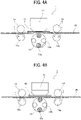
- FIGS. 4A and 4B are side views, each illustrating the image reading device of FIG. 1 , when conveying a cleaning sheet.
- the image reading device 1 includes a reading unit 11, an exposure glass 12, a background switching revolver 13, an upstream conveyance roller pair 14, and a downstream conveyance roller pair 15.
- the reading unit 11 reads a sheet S that is conveyed in the image reading device 1.
- the process of reading the sheet S includes confirmation of the sheet S and reading of an image formed on the sheet S.
- the reading unit 11 uses a contact image sensor that includes a reading unit and an irradiation unit as a single unit.
- the structure of the reading unit 11 is not limited to this structure.
- the exposure glass 12 is a transparent member (reading plate) interposed between the reading unit 11 and the sheet S while being conveyed under the exposure glass 12.
- the background switching revolver 13 is an opposing member disposed facing the reading unit 11 across the exposure glass 12 (transparent member).
- the background switching revolver 13 has two black background rollers 13a and two white background rollers 13b around the circumferential surface. Each of the black background rollers 13a has a black peripheral surface.
- Each of the white background rollers 13b has a white peripheral surface.
- the background switching revolver 13 is rotated to switch a background color in accordance with white shading or a reading target that is an object to be read.
- the upstream conveyance roller pair 14 includes a conveyance roller 14a and a driven roller 14b.
- the conveyance roller 14a and the driven roller 14b are disposed upstream from the reading unit 11 in a conveyance direction in which the sheet S is conveyed.
- the conveyance roller 14a functions as a first conveyance rotator.
- the downstream conveyance roller pair 15 includes a conveyance roller 15a and a driven roller 15b.
- the conveyance roller 15a and the driven roller 15b are disposed downstream from the reading unit 11 in the conveyance direction of the sheet S.
- the conveyance roller 15a functions as a second conveyance rotator.
- a straight conveyance passage 16 and a reverse conveyance passage 17 extend toward downstream in the conveyance direction of the sheet S in the image reading device 1.
- a conveyance roller pair 18 is disposed on the straight conveyance passage 16.
- Conveyance roller pairs 19 including a conveyance roller pair 19A and a conveyance roller pair 19B are disposed on the reverse conveyance passage 17.
- the conveyance roller pair 19B is disposed downstream from the conveyance roller pair 19A in the conveyance direction of the sheet S.
- the sheet S is conveyed through the straight conveyance passage 16 to be ejected with the face up.
- the sheet S is conveyed through the reverse conveyance passage 17 to be ejected with the face down.
- the sheet S is conveyed through the reverse conveyance passage 17 after the first face of the sheet S is printed, and is then conveyed through the straight conveyance passage 16 after the second face of the sheet S.
- the conveyance roller 14a of the upstream conveyance roller pair 14 is driven and rotated by a drive motor 24.
- the conveyance roller 15a of the downstream conveyance roller pair 15 is driven and rotated by a drive motor 25.
- the drive motors 24 and 25 are driven and rotated by a motor driver 21.
- a cleaning controller 20 controls each of driving of the first conveyance rotator (i.e., the conveyance roller 14a) and driving of the second conveyance rotator (i.e., the conveyance roller 15a) via the motor driver 21 when cleaning the exposure glass 12 or the background switching revolver 13.
- the cleaning controller 20 causes the conveyance roller 14a and the conveyance roller 15a to rotate at the conveying speeds different from each other.
- the sheet-like cleaning member 46 is hereinafter referred to as a cleaning sheet 46.
- the cleaning controller 20 causes the cleaning sheet 46 to contact the exposure glass 12 (transparent member) or the background switching revolver 13 (opposing member).
- the image reading device 1 when the sheet S passes below the reading unit 11, the image reading device 1 causes the reading unit 11 to sequentially read the state of the sheet S on a reading line 31, so that the image reading device 1 acquires data of sheet S and data of the image formed on the sheet S.
- the background switching revolver 13 switches the background roller in accordance with the sheet S.
- the sheet S is white
- either one of the black background rollers 13a is brought over the reading line 31.
- either one of white background rollers 13b is brought over the reading line 31.
- FIG. 5 is a plan view of the image reading device, for explaining a foreign material on the exposure glass mounted on the image reading device and the reading result.
- FIG. 6 is a plan view of the image reading device, for explaining the reading result.
- the read image that is read by the reading unit 11 includes not only a sheet reading image 33 and a read background 34 but also a longitudinal streak 35 generated due to the foreign material 32 along the conveyance direction of the sheet S.
- the reading unit 11 cannot read information of the area of the sheet S.
- the reading unit 11 cannot read, even if a defect image is in the area, the reading unit 11 cannot read, resulting in the functional deterioration.
- the reading unit 11 reads the foreign material 32 to determine that the image is defected.
- the reading result of a sheet by the reading unit 11 is not to be affected by foreign materials such as debris.
- the sheet S is paper
- the sheet-like cleaning member (cleaning sheet) 46 is brought to contact the exposure glass 12 or the background switching revolver 13, so as to clean the exposure glass 12 or the background switching revolver 13.
- the cleaning sheet 46 may be a special sheet for cleaning or a sheet S for image formation.
- the cleaning sheet 46 may be, for example, a convex-concave paper or a Japanese paper.
- the cleaning controller 20 causes the number of rotations of the conveyance roller 14a of the upstream conveyance roller pair 14 and the number of rotations of the conveyance roller 15a of the downstream conveyance roller pair 15 to be different from each other.
- the conveyance roller 14a of the upstream conveyance roller pair 14 is referred to as an upstream conveyance roller 14a.
- the conveyance roller 15a of the downstream conveyance roller pair 15 is referred to as a downstream conveyance roller 15a.
- the upstream conveyance roller 14a and the downstream conveyance roller 15a have the same diameter and the different number of rotations from each other. According to this configuration, the upstream conveyance roller 14a and the downstream conveyance roller 15a have the different surface linear velocities from each other, and therefore also have the different conveying speeds from each other.
- the number of rotations of the downstream conveyance roller 15a is smaller than the number of rotations of the upstream conveyance roller 14a.
- the linear velocity of the downstream conveyance roller 15a is slower than the linear velocity of the upstream conveyance roller 14a.
- the cleaning sheet 46 may be bent between the upstream conveyance roller pair 14 and the downstream conveyance roller pair 15 so as to be convex (outward) toward the exposure glass 12.
- the cleaning sheet 46 is conveyed while the cleaning sheet 46 is pressed against the exposure glass 12 with an appropriate pressure, so that the surface of the exposure glass 12 is cleaned.
- the number of rotations of the downstream conveyance roller 15a is greater than the number of rotations of the upstream conveyance roller 14a.
- the linear velocity of the downstream conveyance roller 15a is faster than the linear velocity of the upstream conveyance roller 14a.
- the cleaning sheet 46 is conveyed while being stretched taut between the upstream conveyance roller pair 14 and the downstream conveyance roller pair 15 so as to be reliably contact the circumferential surface of the background switching revolver 13.
- the background switching revolver 13 is rotated to bring the black background roller 13a or the white background roller 13b to the position at which the black background roller 13a or the white background roller 13b contacts the cleaning sheet 46.
- the (circumferential) surface of the black background roller 13a or the (circumferential) surface of the white background roller 13b is cleaned.
- the white shading surface is cleaned similarly.
- the exposure glass 12 or the background face of the background switching revolver 13 is cleaned while the cleaning sheet 46 is in contact with the exposure glass 12 or the background switching revolver 13, thereby enhancing the cleanability in the image reading device 1.
- FIGS. 7A and 7B are side views, each illustrating the image reading device according to the second embodiment of the present disclosure, in the cleaning operation performed on the image reading device.
- FIGS. 8A and 8B are diagrams, each illustrating the cleaning sheet used in the image reading device of FIGS. 7A and 7B .
- the cleaning sheet 46 used in the present embodiment includes a base 46a and brushes 46b for cleaning disposed partly on one side of the base 46a, along the conveyance direction of the cleaning sheet 46.
- the brushes 46b are aligned in a belt-like shape along a direction that intersects with the conveyance direction of the cleaning sheet 46.
- the brushes 46b in FIGS. 8A and 8B are aligned in a direction orthogonal to the conveyance direction of the cleaning sheet 46. However, the brushes 46b may be aligned in an oblique direction to the conveyance direction of the cleaning sheet 46.
- the cleaning sheet 46 When cleaning the exposure glass 12 by the cleaning sheet 46, the cleaning sheet 46 is conveyed with the brushes 46b facing the exposure glass 12, as illustrated in FIG. 7A . At this time, as in the first embodiment, the number of rotations of the downstream conveyance roller 15a is smaller than the number of rotations of the upstream conveyance roller 14a.
- the cleaning sheet 46 is bent to be convex (outward) toward the exposure glass 12, so that the brushes 46b of the cleaning sheet 46 may be brought to contact the exposure glass 12.
- the cleaning sheet 46 is conveyed to wipe and clean the exposure glass 12 by the brushes 46b.
- the cleaning sheet 46 is conveyed with the brushes 46b facing the background switching revolver 13, as illustrated in FIG. 7B .
- the number of rotations of the downstream conveyance roller 15a is greater than the number of rotations of the upstream conveyance roller 14a.
- the cleaning sheet 46 is stretched taut, so that the brushes 46b of the cleaning sheet 46 may be brought to contact the black background roller 13a or the white background roller 13b of the background switching revolver 13.
- the cleaning sheet 46 is conveyed to wipe and clean the circumferential surface of the black background roller 13a or the circumferential surface of the white background roller 13b by the brushes 46b.
- the cleaning sheet 46 includes the brushes 46b for cleaning, thereby further enhancing the cleanability in the image reading device 1.
- the cleaning sheet 46 may dispose the brushes 46b covering the whole surface of the base 46a. Further, in order to prevent instant impact between the brushes 46b of the cleaning sheet 46 and each of the exposure glass 12 and the background switching revolver 13, the distance X from the leading end of the base 46a in the conveyance direction of the cleaning sheet 46 to the first brush 46b of the brushes 46b may be sufficiently obtained.
- FIGS. 9A and 9B are side views, each illustrating the image reading device according to the third embodiment of the present disclosure, in a cleaning operation performed on the image reading device.
- FIGS. 10A and 10B are diagrams, each illustrating the cleaning sheet used in the image reading device of FIGS. 9A and 9B .
- the cleaning sheet 46 used in the present embodiment includes the base 46a and the brushes 46b for cleaning (upper brushes 46b1 and lower brushes 46b2) on both sides, which are front and back sides, of the base 46a, along the conveyance direction of the cleaning sheet 46.
- the upper brushes 46b1 are on the front side of the base 46a and the lower brushes 46b2 are on the back side of the base 46a.
- the upper brushes 46b1 and the lower brushes 46b2 are aligned in a belt-like shape in the direction that intersects with the conveyance direction of the cleaning sheet 46.
- 10A and 10B are aligned in the direction orthogonal to the conveyance direction of the cleaning sheet 46.
- the upper brushes 46b1 and the lower brushes 46b2 may be aligned in the oblique direction to the conveyance direction of the cleaning sheet 46.
- the number of rotations of the downstream conveyance roller 15a is smaller than the number of rotations of the upstream conveyance roller 14a.
- the cleaning sheet 46 is bent to be convex (outward) toward the exposure glass 12, so that the upper brushes 46b1 on the upper surface of the cleaning sheet 46 may be brought to contact the exposure glass 12.
- the lower brushes 46b2 on the lower surface of the cleaning sheet 46 is projected downwardly from the base 46a, the lower brushes 46b2 may be brought to contact the circumferential surface of the background switching revolver 13 (i.e., the circumferential surface of the black background roller 13a or the circumferential surface of the white background roller 13b).
- the cleaning sheet 46 is conveyed with such a configuration, so that the upper brushes 46b1 wipe and clean the surface of the exposure glass 12 and the lower brushes 46b2 wipe and clean the circumferential surface of the background switching revolver 13, in other words, the circumferential surface of the black background roller 13a or the circumferential surface of the white background roller 13b.
- the cleaning sheet 46 includes the upper brushes 46b1 and the lower brushes 46b2, the exposure glass 12 (transparent member) and the background switching revolver 13 (opposing member) are cleaned at one time in one conveyance.
- the upper brushes 46b1 on one side (i.e., upper surface) of the base 46a of the cleaning sheet 46 are disposed at respective positions different from respective positions of the lower brushes 46b2 on the other side (i.e., lower surface) of the base 46a of the cleaning sheet 46 in a zigzag (staggered) pattern as viewed in FIG. 10B .
- the thickness of the cleaning sheet 46 equals the sum of the thickness of the base 46a, the height of the upper brushes 46b1, and the height of the lower brushes 46b2. This structure restrains a decrease in conveyance of the cleaning sheet 46.
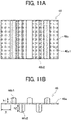
- FIGS. 11A and 11B are diagrams, each illustrating the cleaning sheet used in the cleaning operation performed on the image reading device according to the fourth embodiment of the present disclosure.
- the cleaning sheet 46 used in the present embodiment includes the base 46a and the brushes 46b (i.e., the upper brushes 46b1 and the lower brushes 46b2) on both sides, which are front and back sides, of the base 46a of the cleaning sheet 46, along the conveyance direction of the cleaning sheet 46.
- the upper brushes 46b1 are on one side (i.e., upper surface) of the base 46a and the lower brushes 46b2 are on the other side (i.e., lower surface) of the base 46a.
- the upper brushes 46b1 and the lower brushes 46b2 are aligned in a belt-like shape in the direction that intersects with the conveyance direction of the cleaning sheet 46.
- the upper brushes 46b1 and the lower brushes 46b2 in FIGS. 10A and 10B are aligned in the direction orthogonal to the conveyance direction of the cleaning sheet 46.
- the upper brushes 46b1 and the lower brushes 46b2 may be aligned in the oblique direction to the conveyance direction of the cleaning sheet 46.
- the upper brushes 46b1 on the upper surface that contacts the exposure glass 12 and the lower brushes 46b2 on the lower surface that contacts the circumferential surface of the background switching revolver 13 have different heights (length) from each other. Specifically, the height (length) h2 of the lower brushes 46b2 on the lower surface of the cleaning sheet 46 is higher (longer) than the height (length) h1 of the upper brushes 46b1 on the upper surface of the cleaning sheet 46.
- the lower brushes 46b2 reliably contact the circumferential surface of the background switching revolver 13, thereby restraining defect cleaning of the exposure glass 12 and the background switching revolver 13 included in the image reading device 1.
- a flame-retardant material such as nylon may be preferably used for the brushes 46b including the upper brushes 46b1 and the lower brushes 46b2 of the cleaning sheet 46.
- This structure of the brushes 46b (upper brushes 46b1, lower brushes 46b2) prevents thermal deformation on the cleaning sheet 46 when, for example, the cleaning sheet 46 is conveyed through a fixing device of an image forming apparatus.
- the cleaning sheet 46 may be conveyed through the fixing device under control that the fixing temperature in the fixing device is set to be relatively low.
- a primary transfer portion may be fully separated from sheet S or the transfer bias of the secondary transfer portion and the transfer bias of the primary transfer portion are highly reduced.
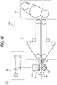
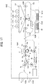
- FIG. 12 is a side view of an image forming apparatus according to the fifth embodiment of the present disclosure.
- An image forming apparatus 100A according to the present embodiment includes an image reading device 1AA, a fixing unit 60, and a cooling unit 70.
- the image forming apparatus 100A according to the present embodiment after an image is fixed to a sheet in the fixing unit 60, the sheet is cooled by the cooling unit 70, then the image on the sheet is read by the image reading device 1AA.
- the image reading device 1AA includes an inline sensor 52 of a reduction optical system.
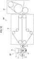
- FIG. 13 is a side view of an image forming apparatus according to the sixth embodiment of the present disclosure.
- An image forming apparatus 100B according to the present embodiment includes an image reading device 1BB, the fixing unit 60, and the cooling unit 70.
- the image forming apparatus 100B according to the present embodiment after an image is fixed to a sheet in the fixing unit 60, the sheet is cooled by the cooling unit 70, then the image on the sheet is read by the image reading device 1BB.
- the image reading device IBB includes an inline sensor 55 of an equal magnification optical system.
- FIG. 14 is a side view of an image forming apparatus according to the seventh embodiment of the present disclosure.
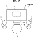
- FIG. 15 is a side view of an image reading device included in the image forming apparatus according to the seventh embodiment of the present disclosure.
- An image forming apparatus 100 includes an image forming device 110, a sheet conveyor 120, an image reader 130, and a controller 150.
- the controller 150 controls an overall operation of the image forming apparatus 100 and a series of processes for forming an image on a sheet S to be used for image formation.
- the controller 150 includes the cleaning controller 20 described in the above-described embodiments.
- the image forming device 110 includes photoconductor drums 112 (namely, photoconductor drums 112Y, 112M, 112C, and 112K) to form latent images corresponding to different single color images.
- the photoconductor drums 112Y, 112M, 112C, and 112K for forming latent images corresponding to images of respective colors are disposed so as to correspond to image forming processes using image forming materials of respective colors such as toners of yellow (Y), magenta (M), cyan (C), and black (K).
- the photoconductor drums 112 are disposed along an intermediate transfer belt 111 that is an endless belt included in a movement assembly.
- the intermediate transfer belt 111 is wound around at least one drive roller and a plurality of driven rollers and moves between a primary transfer position and a secondary transfer position.
- the first transfer position is a position where an image (toner image) developed on the photoconductor drum 112 is transferred and the secondary transfer position is a position where the image (toner image) is transferred to the sheet S.
- a transfer unit 113 is disposed at the secondary transfer position.
- the transfer unit 113 includes a transfer roller 113a and a counter roller 113b disposed opposite the transfer roller 113a.
- the toner image is transferred from the intermediate transfer belt 111 to the sheet S to form an image at a predetermined position (i.e., image forming position) on the sheet S.
- a gap is provided between the transfer roller 113a and the counter roller 113b, so that the intermediate transfer belt 111 and the sheet S pass through the gap while being nipped between the transfer roller 113a and the counter roller 113b.
- An image is transferred onto the sheet S while the sheet S is nipped in the gap between the transfer roller 113a and the counter roller 113b and conveyed in the conveyance direction of the sheet S (sub-scanning direction).
- the sheet conveyor 120 includes a sheet feed tray 121A and a sheet feed tray 121B that functions as a sheet feeder.
- the sheet feed tray 121A loads sheets to be used for image formation.
- the sheet feed tray 121B loads cleaning sheets 46. In other words, the cleaning sheet 46 is fed from a sheet feeder different from a sheet feeder loading the sheet S on which an image is formed.
- the sheet conveyor 120 further includes a conveyance passage 122, a fixing roller pair 123, a conveyance passage switcher 124, and a reversal passage 125.
- the conveyance passage 122 is defined by multiple roller pairs to convey the cleaning sheet 46.
- the fixing roller pair 123 is disposed downstream from the transfer unit 113 in the conveyance direction of the sheet S.
- the sheet S loaded in the sheet feed tray 121A is separated by a pickup roller and conveyed along the conveyance passage 122. Then, the sheet S reaches the transfer unit 113.
- the transfer process is performed. That is, the sheet S is conveyed in the predetermined conveyance direction while being nipped between the surface of the intermediate transfer belt 111 and the counter roller 113b.
- the transfer roller 113a biases (presses) the intermediate transfer belt 111 toward the counter roller 113b.
- an image forming material on the surface of the intermediate transfer belt 111 is transferred onto the sheet S. In this transfer process, an image is formed on one side (first face) of the sheet S.
- the sheet S having the image on the first face is further conveyed, so that the image is fixed to the sheet S by the fixing roller pair 123. Then, the sheet S is conveyed to the conveyance passage switcher 124 disposed downstream from fixing roller pair 123 in the conveyance direction of the sheet S. The conveyance passage switcher 124 reverses the travel direction of the sheet S and conveys the reversed sheet S to the reversal passage 125. Thereafter, the sheet S is conveyed again to the transfer position of the transfer roller 113a so that the image formed on the intermediate transfer belt 111 is transferred onto the second face of the sheet S.
- the sheet S having the image on the second face is further conveyed, so that the image on the second face of the sheet S is fixed to the sheet S by the fixing roller pair 123. Then, the sheet S is conveyed to the image reader 130 disposed downstream from the fixing roller pair 123 in the conveyance direction of the sheet S.
- the image reader 130 includes a reader 130a and a reader 130b.
- the reader 130a is constructed by an image reading device that reads the first face of the sheet S.
- the reader 130b is constructed by an image reading device that reads the second face of the sheet S.
- the sheet S for image formation that has passed through the image reader 130 is ejected to a sheet ejection tray 126A that functions as a sheet stacker.
- the cleaning sheet 46 that has passed through the image reader 130 is ejected to a sheet ejection tray 126B that functions as a sheet stacker.
- the sheet S for image formation and cleaning sheet 46 are ejected to different sheet ejection trays. By so doing, even when a cleaning operation is performed in continuous printing, the cleaning sheet 46 is prevented from being mixed into the sheets S for image formation.
- Each of the readers 130a and 130b of the image reader 130 includes the image reading device 1.
- the image reading device 1 (readers 130a and 130b) includes the reading unit 11 provided with an irradiation unit 11b and a line image sensor.
- the irradiation unit 11b irradiates a sheet S with light when the sheet S passes through a reading position.
- the line image sensor includes imaging elements 11a that perform photoelectric conversion for each pixel.
- the imaging elements 11a are disposed in a one-dimensional shape along a direction orthogonal to the conveyance direction of the sheet S.
- the image reading device 1 repeatedly performs a reading operation of an image for one line extending in the conveyance direction of the sheet S in accordance with a passing operation of the sheet S that passes the reading position, so as to read the image printed on the sheet S as a two-dimensional image.
- the background switching revolver 13 is disposed at a position facing the reading unit 11 across the conveyance passage and reflects irradiation light with which the sheet S is irradiated when reading an image.
- the exposure glass 12 that functions as a transparent member is disposed on the front face of the reading unit 11 and is disposed facing the background switching revolver 13.
- the exposure glass 12 penetrates light emitted from the reading unit 11 and reflected light returning after the emitted light is reflected by the background switching revolver 13 and the sheet S.
- FIG. 16 is a flowchart of a control flow in a cleaning operation in continuous printing executed by a controller according to the seventh embodiment.
- the controller 150 executes continuous printing while detecting a defect image (abnormal image) and correcting a position at which an image is formed or a color tone, based on the reading result of the sheet S by the image reading device 1 (reading device) (step S1, hereinafter referred to as "S1").
- the cleaning sheet 46 is conveyed and the controller 150 determines whether an automatic cleaning mode is ON or OFF (S2). In the automatic cleaning mode, the cleaning sheet 46 cleans the surface of the exposure glass 12 of the image reading device 1 or the surface of the background switching revolver 13 of the image reading device 1.
- the controller 150 determines whether the number of output sheets (number of printed sheets) is equal to or greater than the predetermined number of sheets for entering the automatic cleaning mode (S3).
- the image output is stopped and, for example, the cleaning sheet 46 with the brushes 46b is fed and conveyed from the sheet feed tray 121B, and then the surface of the exposure glass 12 or the surface of the background switching revolver 13 is cleaned by the cleaning sheet 46 (S4).
- the controller 150 determines whether no more cleaning operation is to be performed in the image reading device 1 (reading device) (S5). When another cleaning operation is to be performed in the image reading device 1 (NO in S5), the process goes back to S4 to repeat the operation in S4 until it is determined that no more cleaning operation is to be performed.
- the image reading device 1 since the image reading device 1 has a configuration that automatically enters the automatic cleaning mode and performs the cleaning operation with the cleaning sheet, a preferable image is formed reliably. Note that entering the automatic cleaning mode may be performed, for example, manually or at the end of the job.
- FIG. 17 is a side view of an image forming apparatus according to the eighth embodiment of the present disclosure.
- An image forming apparatus 100C includes the image forming device 110, the sheet conveyor 120, an image reader 130C, and the controller 150.
- the controller 150 controls an overall operation of the image forming apparatus 100C and a series of processes for forming an image on a sheet S to be used for image formation.
- the controller 150 includes the cleaning controller 20 described in the above-described embodiments.
- the image forming device 110 includes photoconductor drums 112 (namely, photoconductor drums 112Y, 112M, 112C, and 112K) to form latent images corresponding to different single color images.
- the photoconductor drums 112Y, 112M, 112C, and 112K for forming latent images corresponding to images of respective colors are disposed so as to correspond to image forming processes using image forming materials of respective colors such as toners of yellow (Y), magenta (M), cyan (C), and black (K).
- the photoconductor drums 112Y, 112M, 112C, and 112 are disposed along the intermediate transfer belt 111 that is an endless belt included in the movement assembly.
- the intermediate transfer belt 111 is wound around at least one drive roller and a plurality of driven rollers and moves between a primary transfer position and a secondary transfer position.
- the first transfer position is a position where an image (toner image) developed on the photoconductor drum 112 is transferred and the secondary transfer position is a position where the image (toner image) is transferred to the sheet S.
- the transfer unit 113 is disposed at the secondary transfer position.
- the transfer unit 113 includes the transfer roller 113a and the counter roller 113b disposed facing the transfer roller 113a.
- the toner image is transferred from the intermediate transfer belt 111 to the sheet S to form an image at a predetermined position (i.e., image forming position) on the sheet S.
- a gap is provided between the transfer roller 113a and the counter roller 113b, so that the intermediate transfer belt 111 and the sheet S pass through the gap while being nipped between the transfer roller 113a and the counter roller 113b.
- An image is transferred onto the sheet S while the sheet S is nipped in the gap between the transfer roller 113a and the counter roller 113b and conveyed in the conveyance direction of the sheet S (sub-scanning direction).
- the sheet conveyor 120 includes the sheet feed tray 121A that functions as a first sheet feeder and the sheet feed tray 121B that functions as a second sheet feeder.
- the sheet feed tray 121A loads sheets to be used for image formation.
- the sheet feed tray 121B loads cleaning sheets 46. In other words, the cleaning sheet 46 is fed from a sheet feeder different from a sheet feeder loading the sheet S on which an image is formed.
- the sheet conveyor 120 receives sheets from the sheet feed tray 121A and includes a conveyance passage 122A, the fixing roller pair 123, the conveyance passage switcher 124, and the reversal passage 125.
- the conveyance passage 122A is defined by multiple roller pairs to convey the sheet S.
- the fixing roller pair 123 is disposed downstream from the transfer unit 113 in the conveyance direction of the sheet S.
- the sheet conveyor 120 also receives sheets from the sheet feed tray 121B and includes a conveyance passage 122B along which the cleaning sheet 46 is conveyed.
- the sheet S loaded in the sheet feed tray 121A is separated by the pickup roller and then conveyed along the conveyance passage 122A. Then, the sheet S reaches the transfer unit 113.
- the transfer process is performed. That is, the sheet S is conveyed in the predetermined conveyance direction while being nipped between the surface of the intermediate transfer belt 111 and the counter roller 113b.
- the transfer roller 113a biases (presses) the intermediate transfer belt 111 toward the counter roller 113b.
- an image forming material on the surface of the intermediate transfer belt 111 is transferred onto the sheet S. In this transfer process, an image is formed on one side (first face) of the sheet S.
- the sheet S having the image on the first face is further conveyed, so that the image is fixed to the sheet S by the fixing roller pair 123. Then, the sheet S is conveyed to the conveyance passage switcher 124 disposed downstream from fixing roller pair 123 in the conveyance direction of the sheet S. The conveyance passage switcher 124 reverses the travel direction of the sheet S and conveys the reversed sheet S to the reversal passage 125. Thereafter, the sheet S is conveyed again to the transfer position of the transfer roller 113a so that the image formed on the intermediate transfer belt 111 is transferred onto the second face of the sheet S.
- the sheet S having the image on the second face is further conveyed, and the image on the second face of the sheet S is fixed to the sheet S by the fixing roller pair 123. Then, the sheet S is conveyed to the image reading device 1 described in the above-described embodiments including the first embodiment.
- the sheet S for image formation passes through the image reading device 1 where the first face of the sheet S is read. Then, the sheet S for image formation is reversed with the first face down by the reverse conveyance passage 17 and then is conveyed to the reversal passage 125. Then, the sheet S for image formation is conveyed by a conveyance roller pair 19C, to the image reading device 1 again. After the second face of the sheet S is read by the image reading device 1, the sheet S is ejected to the sheet ejection tray 126A.
- the cleaning sheet 46 that is conveyed from the sheet feed tray 121B is conveyed through the conveyance passage 122B to the image reading device 1.
- the cleaning sheet 46 that has passed through the image reading device 1 is ejected to the sheet ejection tray 126B.
- the sheet S for image formation and cleaning sheet 46 are ejected to different sheet ejection trays. By so doing, even when a cleaning operation is performed in continuous printing, the cleaning sheet 46 is prevented from being mixed into the sheets S for image formation.
- the cleaning sheet 46 that is conveyed from the sheet feed tray 121B does not pass the transfer unit 113 and the fixing roller pair 123, thereby restraining damage on the cleaning sheet 46 due to toner contamination and heat.
- FIG. 18 is a flowchart of a first control flow in a cleaning operation executed by a controller according to the present embodiment.
- the first example is same as the examples illustrated in FIGS. 4A, 4B , 7A, and 7B of the first embodiment, in which one of the exposure glass 12 and the background switching revolver 13 (one of the cleaning targets) is wiped and cleaned in one conveyance of the cleaning sheet 46.
- the cleaning sheet 46 that is conveyed from the sheet feed tray 121B is conveyed as illustrated in FIGS. 4A and 7A to wipe and clean the exposure glass 12 (S11).
- the controller 150 controls so that the number of rotations of the downstream conveyance roller 14a is greater than the number of rotations of the upstream conveyance roller 15a. In other words, the controller 150 controls to satisfy the following relation: the number of rotations of the downstream conveyance roller 14a > the number of rotations of the upstream conveyance roller 15a.
- the cleaning sheet 46 is conveyed to the reverse conveyance passage 17 (S12), where the cleaning sheet 46 is reversed with the first face down and is conveyed to the image reading device 1 again.
- the cleaning sheet 46 is conveyed as illustrated in FIGS. 4B and 7B to wipe and clean the circumferential surface of the background switching revolver 13, that is, the circumferential surface of the black background roller 13a or the circumferential surface of the white background roller 13b (S13).
- the controller 150 controls so that the number of rotations of the downstream conveyance roller 14a is smaller than the number of rotations of the upstream conveyance roller 15a. In other words, the controller 150 controls to satisfy the following relation: the number of rotations of the downstream conveyance roller 14a ⁇ the number of rotations of the upstream conveyance roller 15a.
- the cleaning sheet 46 is ejected to the sheet ejection tray 126B (S14).
- FIG. 19 is a flowchart of a second control flow in a cleaning operation executed by the controller according to the present embodiment.
- the second example is same as the examples illustrated in FIGS. 9A, 9B , 10A, and 10B of the third embodiment, in which the exposure glass 12 and the background switching revolver 13 (both cleaning targets) are wiped and cleaned in one conveyance of the cleaning sheet 46.
- the controller 150 controls so that the number of rotations of the downstream conveyance roller 14a is greater than the number of rotations of the upstream conveyance roller 15a. In other words, the controller 150 controls to satisfy the following relation: the number of rotations of the downstream conveyance roller 14a > the number of rotations of the upstream conveyance roller 15a.
- the controller 150 determines whether or not another cleaning is to be performed (S22).
- the cleaning sheet 46 is ejected to the sheet ejection tray 126B (S25), and the process ends.
- the cleaning sheet 46 is not conveyed in the reverse conveyance passage 17 to be further conveyed to the image reading device 1 again.
- the cleaning sheet 46 is conveyed to the reverse conveyance passage 17 (S23). Then, the cleaning sheet 46 is conveyed as illustrated in FIGS. 9A and 9B , so as to wipe and clean the exposure glass 12 and the circumferential surface of the background switching revolver 13, that is, the circumferential surface of the black background roller 13a or the circumferential surface of the white background roller 13b (S24).
- the controller 150 controls so that the number of rotations of the downstream conveyance roller 14a is greater than the number of rotations of the upstream conveyance roller 15a. In other words, the controller 150 controls to satisfy the following relation: the number of rotations of the downstream conveyance roller 14a > the number of rotations of the upstream conveyance roller 15a.
- the cleaning sheet 46 is ejected to the sheet ejection tray 126B (S25), and the process ends.
- step S24 the process may return to step S22 in which the controller 150 determines whether further cleaning is to be performed or not. By so doing, the cleaning may be performed for three or more times.
- FIG. 20 is a side view of an image reader included in an image forming apparatus according to the ninth embodiment of the present disclosure.
- the configuration of the image forming apparatus according to the present embodiment is similar to the configuration of the image forming apparatus according to the seventh embodiment, except that the image forming apparatus according to the present embodiment includes an image reader 130 including two readers.
- the image reader 130 includes a downstream reader 130a and an upstream reader 130b.
- the upstream reader 130b is constructed by an image reading device 1B and the downstream reader 130a is constructed by an image reading device 1A.
- the image reading device 1B includes an irradiation unit 11bb and a line image sensor.
- the irradiation unit 11bb irradiates a sheet S with light when the sheet S passes through a reading position.
- the line image sensor includes imaging elements 11ab that perform photoelectric conversion for each pixel.
- the imaging elements 11ab are disposed in a one-dimensional shape along a direction orthogonal to the conveyance direction of the sheet S.
- the image reading device 1B repeatedly performs a reading operation of an image for one line extending in the conveyance direction of the sheet S in accordance with a passing operation of the sheet S that passes the reading position, so as to read the image printed on the sheet S as a two-dimensional image.
- the background switching revolver 13B is disposed at a position facing the reading unit 11B across the conveyance passage and reflects irradiation light with which the sheet S is irradiated when reading an image.
- An exposure glass 12b that functions as a transparent member is disposed on the front face of the reading unit 11B and is disposed facing the background switching revolver 13B.
- the exposure glass 12b penetrates light emitted from the reading unit 11B and reflected light returning after the emitted light is reflected by the background switching revolver 13B and the sheet S.
- An upstream conveyance roller pair 14B including an upstream conveyance roller 14ab is disposed upstream from the reading unit 11B in the conveyance direction of the sheet S.
- a downstream conveyance roller pair 15B including a downstream conveyance roller 15ab is disposed downstream from the reading unit 11B in the conveyance direction of the sheet S.
- the image reading device 1A includes an irradiation unit 11ba and a line image sensor.
- the irradiation unit 11ba irradiates a sheet S with light when the sheet S passes through a reading position.
- the line image sensor includes imaging elements 11aa that perform photoelectric conversion for each pixel.
- the imaging elements 11aa are disposed in a one-dimensional shape along a direction orthogonal to the conveyance direction of the sheet S.
- the image reading device 1A repeatedly performs a reading operation of an image for one line extending in the conveyance direction of the sheet S in accordance with a passing operation of the sheet S that passes the reading position, so as to read the image printed on the sheet S as a two-dimensional image.
- the background switching revolver 13A is disposed at a position facing the reading unit 11A across the conveyance passage and reflects irradiation light with which the sheet S is irradiated when reading an image.
- An upstream conveyance roller pair 14A including an upstream conveyance roller 14aa is disposed upstream from the reading unit 11A in the conveyance direction of the sheet S.
- a downstream conveyance roller pair 15A including a downstream conveyance roller 15aa is disposed downstream from the reading unit 11A in the conveyance direction of the sheet S.
- FIG. 21 is a flowchart of a control flow in a cleaning operation performed on upstream reader according to the ninth embodiment of the present disclosure.
- the cleaning sheet 46 that is conveyed from the sheet feed tray 121B is conveyed to wipe and clean the exposure glass 12b of the image reading device 1B that is disposed upstream in the conveyance direction of the cleaning sheet 46 in the image reader 130 in FIG. 20 (S41).
- the controller 150 controls so that the number of rotations of the downstream conveyance roller 14ab is greater than the number of rotations of the upstream conveyance roller 15ab. In other words, the controller 150 controls to satisfy the following relation: the number of rotations of the downstream conveyance roller 14ab > the number of rotations of the upstream conveyance roller 15ab.
- controller 150 determines whether the trailing end of the cleaning sheet 46 has passed the downstream conveyance roller 15ab (S42).
- step S42 is repeated until the trailing end of the cleaning sheet 46 passes the downstream conveyance roller 15ab.
- the cleaning sheet 46 that is reversed with the first face down is conveyed (S43).
- the reversed cleaning sheet 46 wipes and cleans the circumferential surface of the background switching revolver 13B of the image reading device 1B disposed upstream in the image reader 130 in the conveyance direction of the cleaning sheet 46 (S44).
- the controller 150 controls so that the number of rotations of the downstream conveyance roller 14ab is smaller than the number of rotations of the upstream conveyance roller 15ab.
- the controller 150 controls to satisfy the following relation: the number of rotations of the downstream conveyance roller 14ab ⁇ the number of rotations of the upstream conveyance roller 15ab.
- the controller 150 determines whether the trailing end of the cleaning sheet 46 has passed the downstream conveyance roller 15ab (S45). When the trailing end of the cleaning sheet 46 has not passed the downstream conveyance roller 15ab (NO in S45), step S45 is repeated until the trailing end of the cleaning sheet 46 passes the downstream conveyance roller 15ab. When the trailing end of the cleaning sheet 46 has passed the downstream conveyance roller 15ab (YES in S45), the process ends.
- FIG. 22 is a flowchart of a control flow in a cleaning operation performed on a downstream reading unit according to the ninth embodiment of the present disclosure.
- the cleaning sheet 46 that has passed the image reading device 1B disposed upstream in the image reader 130 in the conveyance direction of the cleaning sheet 46 or another cleaning sheet 46 that is newly conveyed from the sheet feed tray 121B is conveyed to wipe and clean the circumferential surface of the background switching revolver 13A of the image reading device 1A disposed downstream in the image reader 130 in the conveyance direction of the cleaning sheet 46 in FIG. 20 (S51).
- the controller 150 controls so that the number of rotations of the downstream conveyance roller 14aa is greater than the number of rotations of the upstream conveyance roller 15aa. In other words, the controller 150 controls to satisfy the following relation: the number of rotations of the downstream conveyance roller 14aa > the number of rotations of the upstream conveyance roller 15aa.
- controller 150 determines whether the trailing end of the cleaning sheet 46 has passed the downstream conveyance roller 15aa (S52).
- step S52 is repeated until the trailing end of the cleaning sheet 46 passes the downstream conveyance roller 15aa.
- the cleaning sheet 46 is conveyed to the image reading device 1A disposed downstream in the image reader 130 in the conveyance direction of the cleaning sheet 46 and is reversed with the first face down, so that the cleaning sheet 46 wipes and cleans the exposure glass 12a (S53).
- the controller 150 controls so that the number of rotations of the downstream conveyance roller 14aa is smaller than the number of rotations of the upstream conveyance roller 15aa. In other words, the controller 150 controls to satisfy the following relation: the number of rotations of the downstream conveyance roller 14aa ⁇ the number of rotations of the upstream conveyance roller 15aa.
- the controller 150 determines whether the trailing end of the cleaning sheet 46 has passed the downstream conveyance roller 15aa (S54). When the trailing end of the cleaning sheet 46 has not passed the downstream conveyance roller 15aa (NO in S54), step S54 is repeated until the trailing end of the cleaning sheet 46 passes the downstream conveyance roller 15aa. When the trailing end of the cleaning sheet 46 has passed the downstream conveyance roller 15aa (YES in S54), the process ends.
- FIG. 23 is a diagram illustrating a black background roller of a background switching revolver according to the tenth embodiment of the present disclosure, for explaining a relation of the black background roller and each of the width of a sheet and the width of a cleaning sheet.
- cleaning is performed with a cleaning sheet that has a width wider than the width of a sheet S to be read by the image reading device 1.
- cleaning is performed with a cleaning sheet that has a width wider than the width of the sheet S in a direction orthogonal to the conveyance direction of the sheet S.
- the background roller of the background switching revolver 13 is switched to the black background roller 13a. By so doing, the reading unit 11 reads the end boundary of the white sheet S.
- a width L2 of the cleaning sheet 46 is preferably greater than the maximum width L1 of sheet S to be conveyed. As a result, the cleaning sheet 46 wipes and cleans dirt on the black background roller 13a near the maximum width of sheet S. Due to this configuration, degradation in reading of the end boundary of the sheet S having the maximum width is restrained.
Landscapes
- Engineering & Computer Science (AREA)
- Multimedia (AREA)
- Signal Processing (AREA)
- Microelectronics & Electronic Packaging (AREA)
- Physics & Mathematics (AREA)
- General Physics & Mathematics (AREA)
- Facsimile Scanning Arrangements (AREA)
- Mechanical Engineering (AREA)
Abstract
Description
- Embodiments of the present disclosure relate to an image reading device and an image forming apparatus incorporating the image reading device.
- Various image forming apparatuses are known to include an image reading device that reads a sheet material on which an image is formed, so as to use the reading result for detecting a defect image (abnormal image) and correcting the position and the color of the image to be formed.
- A known image forming apparatus disclosed in
Japanese Unexamined Patent Application Publication No. 2016-111654 - However, the configuration disclosed in
Japanese Unexamined Patent Application Publication No. 2016-111654 - An object of the present disclosure is to provide an image reading device to enhance the cleanability in an image reading device.
- Embodiments of the present disclosure described herein provide a novel image reading device including a reader, a transparent member, an opposing member, a first conveyance rotator, a second conveyance rotator, and a controller. The reader reads a sheet. The transparent member is disposed between the reader and the sheet facing the reader. The opposing member is disposed facing the reader via the transparent member. The first conveyance rotator is disposed upstream from the reader in a conveyance direction of the sheet. The second conveyance rotator is disposed downstream from the reader in the conveyance direction. The controller causes the first conveyance rotator and the second conveyance rotator to convey a cleaning sheet at respective conveying speeds different from each other and bring the cleaning sheet into contact with at least one of the transparent member or the opposing member.
- Further, embodiments of the present disclosure described herein provide an image forming apparatus including an image forming device configured to form an image on a sheet, and the above-described image reading device to read the image on the sheet.
- According to an embodiment of the present disclosure, the cleanability in an image reading device is enhanced.
- Exemplary embodiments of this disclosure will be described in detail based on the following figures, wherein:
-
FIG. 1 is a diagram illustrating an image reading device according to a first embodiment of the present disclosure and a conveyance passage through which a reading target object passes; -
FIG. 2 is a side view of the image reading device ofFIG. 1 , when conveying a sheet; -
FIG. 3 is a plan view of the image reading device ofFIG. 1 , when conveying the sheet; -
FIGS. 4A and 4B are side views, each illustrating the image reading device ofFIG. 1 , when conveying a cleaning sheet; -
FIG. 5 is a plan view of the image reading device ofFIG. 1 , for explaining a foreign material on an exposure glass mounted on the image reading device and the reading result; -
FIG. 6 is a plan view of the image reading device ofFIG. 1 , for explaining the reading result; -
FIGS. 7A and 7B are side views, each illustrating an image reading device according to a second embodiment of the present disclosure, in a cleaning operation performed on the image reading device; -
FIGS. 8A and 8B are diagrams, each illustrating a cleaning sheet used in the image reading device ofFIGS. 7A and 7B ; -
FIGS. 9A and 9B are side views, each illustrating an image reading device according to a third embodiment of the present disclosure, in a cleaning operation performed on the image reading device; -
FIGS. 10A and 10B are diagrams, each illustrating a cleaning sheet used in the image reading device ofFIGS. 9A and 9B ; -
FIGS. 11A and 11B are diagrams, each illustrating a cleaning sheet used in a cleaning operation performed on an image reading device according to a fourth embodiment of the present disclosure; -
FIG. 12 is a side view of an image forming apparatus according to a fifth embodiment of the present disclosure; -
FIG. 13 is a side view of an image forming apparatus according to a sixth embodiment of the present disclosure; -
FIG. 14 is a side view of an image forming apparatus according to a seventh embodiment of the present disclosure; -
FIG. 15 is a side view of an image reading device included in the image forming apparatus ofFIG. 14 ; -
FIG. 16 is a flowchart of a control flow in a cleaning operation in continuous printing executed by a controller according to the seventh embodiment; -
FIG. 17 is a side view of an image forming apparatus according to an eighth embodiment of the present disclosure; -
FIG. 18 is a flowchart of a first control flow in a cleaning operation executed by a controller according to the eighth embodiment; -
FIG. 19 is a flowchart of a second control flow in a cleaning operation executed by the controller according to the eighth embodiment; -
FIG. 20 is a side view of an image reader included in an image forming apparatus according to a ninth embodiment of the present disclosure; -
FIG. 21 is a flowchart of a control flow in a cleaning operation performed on upstream reader according to the ninth embodiment; -
FIG. 22 is a flowchart of a control flow in a cleaning operation performed on a downstream reading unit according to the ninth embodiment; and -
FIG. 23 is a diagram illustrating a black background roller of a background switching revolver according to a tenth embodiment of the present disclosure, for explaining a relation of the black background roller and each of the width of a sheet and the width of a cleaning sheet. - The accompanying drawings are intended to depict embodiments of the present disclosure and should not be interpreted to limit the scope thereof. The accompanying drawings are not to be considered as drawn to scale unless explicitly noted.
- It will be understood that if an element or layer is referred to as being "on," "against," "connected to" or "coupled to" another element or layer, then it can be directly on, against, connected or coupled to the other element or layer, or intervening elements or layers may be present. In contrast, if an element is referred to as being "directly on," "directly connected to" or "directly coupled to" another element or layer, then there are no intervening elements or layers present. Like numbers referred to like elements throughout. As used herein, the term "and/or" includes any and all combinations of one or more of the associated listed items.
- Spatially relative terms, such as "beneath," "below," "lower," "above," "upper" and the like may be used herein for ease of description to describe one element or feature's relationship to another element(s) or feature(s) as illustrated in the figures. It will be understood that the spatially relative terms are intended to encompass different orientations of the device in use or operation in addition to the orientation depicted in the figures. For example, if the device in the figures is turned over, elements describes as "below" or "beneath" other elements or features would then be oriented "above" the other elements or features. Thus, term such as "below" can encompass both an orientation of above and below. The device may be otherwise oriented (rotated 90 degrees or at other orientations) and the spatially relative descriptors herein interpreted accordingly.
- The terminology used herein is for describing particular embodiments and examples and is not intended to be limiting of exemplary embodiments of this disclosure. As used herein, the singular forms "a," "an," and "the" are intended to include the plural forms as well, unless the context clearly indicates otherwise. It will be further understood that the terms "includes" and/or "including," when used in this specification, specify the presence of stated features, integers, steps, operations, elements, and/or components, but do not preclude the presence or addition of one or more other features, integers, steps, operations, elements, components, and/or groups thereof.
- Referring now to the drawings, embodiments of the present disclosure are described below. In the drawings for explaining the following embodiments, the same reference codes are allocated to elements (members or components) having the same function or shape and redundant descriptions thereof are omitted below.
- Next, a description is given of a configuration and functions of an image reading device and an image forming apparatus, according to an embodiment of the present disclosure, with reference to drawings. Note that identical parts or equivalents are given identical reference numerals and redundant descriptions are summarized or omitted accordingly.
- Embodiments of the present disclosure are described below with reference to the attached drawings.
- A description is given of a first embodiment of the present disclosure, with reference to
FIGS. 1 to 4B . -
FIG. 1 is a diagram illustrating an image reading device according to a first embodiment of the present disclosure and a conveyance passage through which a reading target passes. -
FIG. 2 is a side view of the image reading device ofFIG. 1 , when conveying a sheet. -
FIG. 3 is a plan view of the image reading device ofFIG. 1 , when conveying the sheet. -
FIGS. 4A and 4B are side views, each illustrating the image reading device ofFIG. 1 , when conveying a cleaning sheet. - The
image reading device 1 includes areading unit 11, anexposure glass 12, abackground switching revolver 13, an upstreamconveyance roller pair 14, and a downstreamconveyance roller pair 15. - The
reading unit 11 reads a sheet S that is conveyed in theimage reading device 1. The process of reading the sheet S includes confirmation of the sheet S and reading of an image formed on the sheet S. In the present embodiment, thereading unit 11 uses a contact image sensor that includes a reading unit and an irradiation unit as a single unit. However, the structure of thereading unit 11 is not limited to this structure. - The
exposure glass 12 is a transparent member (reading plate) interposed between the readingunit 11 and the sheet S while being conveyed under theexposure glass 12. - The
background switching revolver 13 is an opposing member disposed facing thereading unit 11 across the exposure glass 12 (transparent member). Thebackground switching revolver 13 has twoblack background rollers 13a and twowhite background rollers 13b around the circumferential surface. Each of theblack background rollers 13a has a black peripheral surface. Each of thewhite background rollers 13b has a white peripheral surface. Thebackground switching revolver 13 is rotated to switch a background color in accordance with white shading or a reading target that is an object to be read. - The upstream
conveyance roller pair 14 includes aconveyance roller 14a and a drivenroller 14b. Theconveyance roller 14a and the drivenroller 14b are disposed upstream from thereading unit 11 in a conveyance direction in which the sheet S is conveyed. Theconveyance roller 14a functions as a first conveyance rotator. The downstreamconveyance roller pair 15 includes aconveyance roller 15a and a drivenroller 15b. Theconveyance roller 15a and the drivenroller 15b are disposed downstream from thereading unit 11 in the conveyance direction of the sheet S. Theconveyance roller 15a functions as a second conveyance rotator. - A
straight conveyance passage 16 and areverse conveyance passage 17 extend toward downstream in the conveyance direction of the sheet S in theimage reading device 1. Aconveyance roller pair 18 is disposed on thestraight conveyance passage 16. Conveyance roller pairs 19 including aconveyance roller pair 19A and aconveyance roller pair 19B are disposed on thereverse conveyance passage 17. Theconveyance roller pair 19B is disposed downstream from theconveyance roller pair 19A in the conveyance direction of the sheet S. - The sheet S is conveyed through the
straight conveyance passage 16 to be ejected with the face up. By contrast, the sheet S is conveyed through thereverse conveyance passage 17 to be ejected with the face down. Alternatively, in duplex printing, the sheet S is conveyed through thereverse conveyance passage 17 after the first face of the sheet S is printed, and is then conveyed through thestraight conveyance passage 16 after the second face of the sheet S. - The
conveyance roller 14a of the upstreamconveyance roller pair 14 is driven and rotated by adrive motor 24. Theconveyance roller 15a of the downstreamconveyance roller pair 15 is driven and rotated by adrive motor 25. Thedrive motors motor driver 21. - A cleaning
controller 20 controls each of driving of the first conveyance rotator (i.e., theconveyance roller 14a) and driving of the second conveyance rotator (i.e., theconveyance roller 15a) via themotor driver 21 when cleaning theexposure glass 12 or thebackground switching revolver 13. - When a sheet-
like cleaning member 46 is conveyed to clean theexposure glass 12 or thebackground switching revolver 13, the cleaningcontroller 20 causes theconveyance roller 14a and theconveyance roller 15a to rotate at the conveying speeds different from each other. The sheet-like cleaning member 46 is hereinafter referred to as acleaning sheet 46. - In the present embodiment, by setting the number of rotations of the
conveyance roller 14a and the number of rotations of theconveyance roller 15a different from each other, the cleaningcontroller 20 causes thecleaning sheet 46 to contact the exposure glass 12 (transparent member) or the background switching revolver 13 (opposing member). - Next, a description is given of operations of reading the sheet S by the
image reading device 1. - As illustrated in
FIGS. 2 and 3 , when the sheet S passes below thereading unit 11, theimage reading device 1 causes thereading unit 11 to sequentially read the state of the sheet S on areading line 31, so that theimage reading device 1 acquires data of sheet S and data of the image formed on the sheet S. - At this time, the
background switching revolver 13 switches the background roller in accordance with the sheet S. When the sheet S is white, either one of theblack background rollers 13a is brought over thereading line 31. When the sheet S is black or when showthrough of an image is concerned, either one ofwhite background rollers 13b is brought over thereading line 31. - Next, a description is given of the image reading device with an example of a foreign material on the exposure glass and a reading result, with reference to
FIGS. 5 and 6 . -
FIG. 5 is a plan view of the image reading device, for explaining a foreign material on the exposure glass mounted on the image reading device and the reading result. -
FIG. 6 is a plan view of the image reading device, for explaining the reading result. - As illustrated in
FIG. 5 , it is assumed that aforeign material 32 is adhered on theexposure glass 12 on thereading line 31 on which thereading unit 11 reads the sheet S. When thereading unit 11 reads the sheet S with theforeign material 32 adhered on thereading line 31, a read image as illustrated inFIG. 6 is produced. - The read image that is read by the
reading unit 11 includes not only asheet reading image 33 and a readbackground 34 but also alongitudinal streak 35 generated due to theforeign material 32 along the conveyance direction of the sheet S. - As described above, when the
foreign material 32 is adhered on thereading line 31, theforeign material 32 blocks irradiation light from thereading unit 11. For this reason, when theforeign material 32 is adhered in an area on thereading line 31, thereading unit 11 cannot read information of the area of the sheet S. When the area of the sheet S cannot be read, even if a defect image is in the area, thereading unit 11 cannot read, resulting in the functional deterioration. Alternatively, even when there is no defect in the image, it is likely that thereading unit 11 reads theforeign material 32 to determine that the image is defected. - In order to avoid this situation, it is highly desirable that the reading result of a sheet by the
reading unit 11 is not to be affected by foreign materials such as debris. However, in a case in which the sheet S is paper, it is difficult to avoid such an adverse effect on the sheet S due to various causes of occurrence of foreign materials such as paper dust or toner in an image forming apparatus. - In order to avoid this situation, in the present embodiment, the sheet-like cleaning member (cleaning sheet) 46 is brought to contact the
exposure glass 12 or thebackground switching revolver 13, so as to clean theexposure glass 12 or thebackground switching revolver 13. Note that thecleaning sheet 46 may be a special sheet for cleaning or a sheet S for image formation. Thecleaning sheet 46 may be, for example, a convex-concave paper or a Japanese paper. - Next, a description is given of a cleaning operation performed when cleaning an exposure glass or a background switching revolver, according to the present embodiment.
- As described above, when cleaning the
exposure glass 12 or thebackground switching revolver 13, the cleaningcontroller 20 causes the number of rotations of theconveyance roller 14a of the upstreamconveyance roller pair 14 and the number of rotations of theconveyance roller 15a of the downstreamconveyance roller pair 15 to be different from each other. For convenience, theconveyance roller 14a of the upstreamconveyance roller pair 14 is referred to as anupstream conveyance roller 14a. Similarly, theconveyance roller 15a of the downstreamconveyance roller pair 15 is referred to as adownstream conveyance roller 15a. Note that, in the present embodiment, theupstream conveyance roller 14a and thedownstream conveyance roller 15a have the same diameter and the different number of rotations from each other. According to this configuration, theupstream conveyance roller 14a and thedownstream conveyance roller 15a have the different surface linear velocities from each other, and therefore also have the different conveying speeds from each other. - As illustrated in
FIG. 4A , when thecleaning sheet 46 is conveyed to clean the exposure glass 12 (transparent member), the number of rotations of thedownstream conveyance roller 15a is smaller than the number of rotations of theupstream conveyance roller 14a. At this time, the linear velocity of thedownstream conveyance roller 15a is slower than the linear velocity of theupstream conveyance roller 14a. - As a result, the
cleaning sheet 46 may be bent between the upstreamconveyance roller pair 14 and the downstreamconveyance roller pair 15 so as to be convex (outward) toward theexposure glass 12. With such a configuration, thecleaning sheet 46 is conveyed while thecleaning sheet 46 is pressed against theexposure glass 12 with an appropriate pressure, so that the surface of theexposure glass 12 is cleaned. - As illustrated in
FIG. 4B , when thecleaning sheet 46 is conveyed to clean the background switching revolver 13 (opposing member), the number of rotations of thedownstream conveyance roller 15a is greater than the number of rotations of theupstream conveyance roller 14a. At this time, the linear velocity of thedownstream conveyance roller 15a is faster than the linear velocity of theupstream conveyance roller 14a. - As a result, as illustrated in
FIG. 4B , thecleaning sheet 46 is conveyed while being stretched taut between the upstreamconveyance roller pair 14 and the downstreamconveyance roller pair 15 so as to be reliably contact the circumferential surface of thebackground switching revolver 13. With such a configuration, thebackground switching revolver 13 is rotated to bring theblack background roller 13a or thewhite background roller 13b to the position at which theblack background roller 13a or thewhite background roller 13b contacts thecleaning sheet 46. By so doing, the (circumferential) surface of theblack background roller 13a or the (circumferential) surface of thewhite background roller 13b is cleaned. The white shading surface is cleaned similarly. - As described above, the
exposure glass 12 or the background face of thebackground switching revolver 13 is cleaned while thecleaning sheet 46 is in contact with theexposure glass 12 or thebackground switching revolver 13, thereby enhancing the cleanability in theimage reading device 1. - Next, a description is given of the image reading device according to a second embodiment of the present disclosure, with reference to
FIGS. 7A to 8B . -
FIGS. 7A and 7B are side views, each illustrating the image reading device according to the second embodiment of the present disclosure, in the cleaning operation performed on the image reading device. -
FIGS. 8A and 8B are diagrams, each illustrating the cleaning sheet used in the image reading device ofFIGS. 7A and 7B . - As illustrated in
FIGS. 8A and 8B , thecleaning sheet 46 used in the present embodiment includes abase 46a and brushes 46b for cleaning disposed partly on one side of thebase 46a, along the conveyance direction of thecleaning sheet 46. Thebrushes 46b are aligned in a belt-like shape along a direction that intersects with the conveyance direction of thecleaning sheet 46. Thebrushes 46b inFIGS. 8A and 8B are aligned in a direction orthogonal to the conveyance direction of thecleaning sheet 46. However, thebrushes 46b may be aligned in an oblique direction to the conveyance direction of thecleaning sheet 46. - Further, in order to prevent instant impact between the
brushes 46b of thecleaning sheet 46 and each of theexposure glass 12 and thebackground switching revolver 13, it is preferable to sufficiently obtain a distance X from the leading end of thebase 46a in the conveyance direction of thecleaning sheet 46, to thefirst brush 46b of thebrushes 46b. - When cleaning the
exposure glass 12 by thecleaning sheet 46, thecleaning sheet 46 is conveyed with thebrushes 46b facing theexposure glass 12, as illustrated inFIG. 7A . At this time, as in the first embodiment, the number of rotations of thedownstream conveyance roller 15a is smaller than the number of rotations of theupstream conveyance roller 14a. - As a result, the
cleaning sheet 46 is bent to be convex (outward) toward theexposure glass 12, so that thebrushes 46b of thecleaning sheet 46 may be brought to contact theexposure glass 12. With such a configuration, thecleaning sheet 46 is conveyed to wipe and clean theexposure glass 12 by thebrushes 46b. - When cleaning the
background switching revolver 13 with thecleaning sheet 46, thecleaning sheet 46 is conveyed with thebrushes 46b facing thebackground switching revolver 13, as illustrated inFIG. 7B . At this time, as in the first embodiment, the number of rotations of thedownstream conveyance roller 15a is greater than the number of rotations of theupstream conveyance roller 14a. - As a result, the
cleaning sheet 46 is stretched taut, so that thebrushes 46b of thecleaning sheet 46 may be brought to contact theblack background roller 13a or thewhite background roller 13b of thebackground switching revolver 13. With such a configuration, thecleaning sheet 46 is conveyed to wipe and clean the circumferential surface of theblack background roller 13a or the circumferential surface of thewhite background roller 13b by thebrushes 46b. - As described above, the
cleaning sheet 46 includes thebrushes 46b for cleaning, thereby further enhancing the cleanability in theimage reading device 1. - Note that, instead of disposing the
brushes 46b partly on thecleaning sheet 46, thecleaning sheet 46 may dispose thebrushes 46b covering the whole surface of thebase 46a. Further, in order to prevent instant impact between thebrushes 46b of thecleaning sheet 46 and each of theexposure glass 12 and thebackground switching revolver 13, the distance X from the leading end of thebase 46a in the conveyance direction of thecleaning sheet 46 to thefirst brush 46b of thebrushes 46b may be sufficiently obtained. - Next, a description is given of the image reading device according to a third embodiment of the present disclosure, with reference to
FIGS. 9A to 10B . -
FIGS. 9A and 9B are side views, each illustrating the image reading device according to the third embodiment of the present disclosure, in a cleaning operation performed on the image reading device. -
FIGS. 10A and 10B are diagrams, each illustrating the cleaning sheet used in the image reading device ofFIGS. 9A and 9B . - As illustrated in
FIGS. 10A and 10B , thecleaning sheet 46 used in the present embodiment includes thebase 46a and thebrushes 46b for cleaning (upper brushes 46b1 and lower brushes 46b2) on both sides, which are front and back sides, of thebase 46a, along the conveyance direction of thecleaning sheet 46. Specifically, the upper brushes 46b1 are on the front side of thebase 46a and the lower brushes 46b2 are on the back side of thebase 46a. The upper brushes 46b1 and the lower brushes 46b2 are aligned in a belt-like shape in the direction that intersects with the conveyance direction of thecleaning sheet 46. The upper brushes 46b1 and the lower brushes 46b2 inFIGS. 10A and 10B are aligned in the direction orthogonal to the conveyance direction of thecleaning sheet 46. However, the upper brushes 46b1 and the lower brushes 46b2 may be aligned in the oblique direction to the conveyance direction of thecleaning sheet 46. - Further, in order to prevent instant impact between the upper brushes 46b1 of the
cleaning sheet 46 and each of theexposure glass 12 and thebackground switching revolver 13, it is preferable to sufficiently obtain the distance X from the leading end of thebase 46a in the conveyance direction of thecleaning sheet 46 to the first upper brush 46b1 of the upper brushes 46b1. - When cleaning the
exposure glass 12 and thebackground switching revolver 13 by thecleaning sheet 46 illustrated inFIGS. 10A and 10B , as in the first embodiment, the number of rotations of thedownstream conveyance roller 15a is smaller than the number of rotations of theupstream conveyance roller 14a. - As a result, as illustrated in
FIG. 9A , thecleaning sheet 46 is bent to be convex (outward) toward theexposure glass 12, so that the upper brushes 46b1 on the upper surface of thecleaning sheet 46 may be brought to contact theexposure glass 12. In addition, as illustrated inFIG. 9B , since the lower brushes 46b2 on the lower surface of thecleaning sheet 46 is projected downwardly from thebase 46a, the lower brushes 46b2 may be brought to contact the circumferential surface of the background switching revolver 13 (i.e., the circumferential surface of theblack background roller 13a or the circumferential surface of thewhite background roller 13b). - The
cleaning sheet 46 is conveyed with such a configuration, so that the upper brushes 46b1 wipe and clean the surface of theexposure glass 12 and the lower brushes 46b2 wipe and clean the circumferential surface of thebackground switching revolver 13, in other words, the circumferential surface of theblack background roller 13a or the circumferential surface of thewhite background roller 13b. - As described above, since the
cleaning sheet 46 includes the upper brushes 46b1 and the lower brushes 46b2, the exposure glass 12 (transparent member) and the background switching revolver 13 (opposing member) are cleaned at one time in one conveyance. - Further, in the present embodiment, the upper brushes 46b1 on one side (i.e., upper surface) of the
base 46a of thecleaning sheet 46 are disposed at respective positions different from respective positions of the lower brushes 46b2 on the other side (i.e., lower surface) of thebase 46a of thecleaning sheet 46 in a zigzag (staggered) pattern as viewed inFIG. 10B . - As a result, in cleaning with the
cleaning sheet 46, the thickness of thecleaning sheet 46 equals the sum of the thickness of thebase 46a, the height of the upper brushes 46b1, and the height of the lower brushes 46b2. This structure restrains a decrease in conveyance of thecleaning sheet 46. - Next, a description is given of the image reading device according to a fourth embodiment of the present disclosure, with reference to
FIGS. 11A and 11B . -
FIGS. 11A and 11B are diagrams, each illustrating the cleaning sheet used in the cleaning operation performed on the image reading device according to the fourth embodiment of the present disclosure. - As illustrated in
FIGS. 11A and 11B , as in the third embodiment, thecleaning sheet 46 used in the present embodiment includes thebase 46a and thebrushes 46b (i.e., the upper brushes 46b1 and the lower brushes 46b2) on both sides, which are front and back sides, of thebase 46a of thecleaning sheet 46, along the conveyance direction of thecleaning sheet 46. Specifically, the upper brushes 46b1 are on one side (i.e., upper surface) of thebase 46a and the lower brushes 46b2 are on the other side (i.e., lower surface) of thebase 46a. The upper brushes 46b1 and the lower brushes 46b2 are aligned in a belt-like shape in the direction that intersects with the conveyance direction of thecleaning sheet 46. The upper brushes 46b1 and the lower brushes 46b2 inFIGS. 10A and 10B are aligned in the direction orthogonal to the conveyance direction of thecleaning sheet 46. However, the upper brushes 46b1 and the lower brushes 46b2 may be aligned in the oblique direction to the conveyance direction of thecleaning sheet 46. - The upper brushes 46b1 on the upper surface that contacts the
exposure glass 12 and the lower brushes 46b2 on the lower surface that contacts the circumferential surface of thebackground switching revolver 13 have different heights (length) from each other. Specifically, the height (length) h2 of the lower brushes 46b2 on the lower surface of thecleaning sheet 46 is higher (longer) than the height (length) h1 of the upper brushes 46b1 on the upper surface of thecleaning sheet 46. - As a result, as in the third embodiment, when the
cleaning sheet 46 is conveyed while thecleaning sheet 46 is bent so as to be convex (outward) toward theexposure glass 12, the lower brushes 46b2 reliably contact the circumferential surface of thebackground switching revolver 13, thereby restraining defect cleaning of theexposure glass 12 and thebackground switching revolver 13 included in theimage reading device 1. - Note that a flame-retardant material such as nylon may be preferably used for the
brushes 46b including the upper brushes 46b1 and the lower brushes 46b2 of thecleaning sheet 46. This structure of thebrushes 46b (upper brushes 46b1, lower brushes 46b2) prevents thermal deformation on thecleaning sheet 46 when, for example, thecleaning sheet 46 is conveyed through a fixing device of an image forming apparatus. In this case, thecleaning sheet 46 may be conveyed through the fixing device under control that the fixing temperature in the fixing device is set to be relatively low. At this time, in order to prevent contamination on the background of sheet S in a secondary transfer portion, a primary transfer portion may be fully separated from sheet S or the transfer bias of the secondary transfer portion and the transfer bias of the primary transfer portion are highly reduced. - Next, a description is given of an image forming apparatus according to a fifth embodiment of the present disclosure, with reference to
FIG. 12 . -
FIG. 12 is a side view of an image forming apparatus according to the fifth embodiment of the present disclosure. - An
image forming apparatus 100A according to the present embodiment includes an image reading device 1AA, a fixingunit 60, and acooling unit 70. In theimage forming apparatus 100A according to the present embodiment, after an image is fixed to a sheet in the fixingunit 60, the sheet is cooled by the coolingunit 70, then the image on the sheet is read by the image reading device 1AA. - The image reading device 1AA includes an
inline sensor 52 of a reduction optical system. - Next, a description is given of an image forming apparatus according to a sixth embodiment of the present disclosure, with reference to
FIG. 13 . -
FIG. 13 is a side view of an image forming apparatus according to the sixth embodiment of the present disclosure. - An
image forming apparatus 100B according to the present embodiment includes an image reading device 1BB, the fixingunit 60, and thecooling unit 70. In theimage forming apparatus 100B according to the present embodiment, after an image is fixed to a sheet in the fixingunit 60, the sheet is cooled by the coolingunit 70, then the image on the sheet is read by the image reading device 1BB. - The image reading device IBB includes an
inline sensor 55 of an equal magnification optical system. - Next, a description is given of an image forming apparatus according to a seventh embodiment of the present disclosure, with reference to
FIGS. 14 and15 . -
FIG. 14 is a side view of an image forming apparatus according to the seventh embodiment of the present disclosure. -
FIG. 15 is a side view of an image reading device included in the image forming apparatus according to the seventh embodiment of the present disclosure. - An
image forming apparatus 100 includes animage forming device 110, asheet conveyor 120, animage reader 130, and acontroller 150. Thecontroller 150 controls an overall operation of theimage forming apparatus 100 and a series of processes for forming an image on a sheet S to be used for image formation. Thecontroller 150 includes the cleaningcontroller 20 described in the above-described embodiments. - The
image forming device 110 includes photoconductor drums 112 (namely,photoconductor drums image forming device 110 according to the present embodiment, the photoconductor drums 112Y, 112M, 112C, and 112K for forming latent images corresponding to images of respective colors are disposed so as to correspond to image forming processes using image forming materials of respective colors such as toners of yellow (Y), magenta (M), cyan (C), and black (K). - The photoconductor drums 112 are disposed along an
intermediate transfer belt 111 that is an endless belt included in a movement assembly. Theintermediate transfer belt 111 is wound around at least one drive roller and a plurality of driven rollers and moves between a primary transfer position and a secondary transfer position. The first transfer position is a position where an image (toner image) developed on the photoconductor drum 112 is transferred and the secondary transfer position is a position where the image (toner image) is transferred to the sheet S. - A
transfer unit 113 is disposed at the secondary transfer position. Thetransfer unit 113 includes atransfer roller 113a and acounter roller 113b disposed opposite thetransfer roller 113a. In thetransfer unit 113, the toner image is transferred from theintermediate transfer belt 111 to the sheet S to form an image at a predetermined position (i.e., image forming position) on the sheet S. A gap is provided between thetransfer roller 113a and thecounter roller 113b, so that theintermediate transfer belt 111 and the sheet S pass through the gap while being nipped between thetransfer roller 113a and thecounter roller 113b. An image is transferred onto the sheet S while the sheet S is nipped in the gap between thetransfer roller 113a and thecounter roller 113b and conveyed in the conveyance direction of the sheet S (sub-scanning direction). - The
sheet conveyor 120 includes asheet feed tray 121A and asheet feed tray 121B that functions as a sheet feeder. Thesheet feed tray 121A loads sheets to be used for image formation. Thesheet feed tray 121Bloads cleaning sheets 46. In other words, thecleaning sheet 46 is fed from a sheet feeder different from a sheet feeder loading the sheet S on which an image is formed. - The
sheet conveyor 120 further includes aconveyance passage 122, a fixingroller pair 123, aconveyance passage switcher 124, and areversal passage 125. Theconveyance passage 122 is defined by multiple roller pairs to convey thecleaning sheet 46. The fixingroller pair 123 is disposed downstream from thetransfer unit 113 in the conveyance direction of the sheet S. - When the image forming process is performed, under the predetermined control processing by the
controller 150, the sheet S loaded in thesheet feed tray 121A is separated by a pickup roller and conveyed along theconveyance passage 122. Then, the sheet S reaches thetransfer unit 113. - As the sheet S reaches the
transfer unit 113, the transfer process is performed. That is, the sheet S is conveyed in the predetermined conveyance direction while being nipped between the surface of theintermediate transfer belt 111 and thecounter roller 113b. Thetransfer roller 113a biases (presses) theintermediate transfer belt 111 toward thecounter roller 113b. When the sheet S passes between theintermediate transfer belt 111 and thecounter roller 113b, an image forming material on the surface of theintermediate transfer belt 111 is transferred onto the sheet S. In this transfer process, an image is formed on one side (first face) of the sheet S. - The sheet S having the image on the first face is further conveyed, so that the image is fixed to the sheet S by the fixing
roller pair 123. Then, the sheet S is conveyed to theconveyance passage switcher 124 disposed downstream from fixingroller pair 123 in the conveyance direction of the sheet S. Theconveyance passage switcher 124 reverses the travel direction of the sheet S and conveys the reversed sheet S to thereversal passage 125. Thereafter, the sheet S is conveyed again to the transfer position of thetransfer roller 113a so that the image formed on theintermediate transfer belt 111 is transferred onto the second face of the sheet S. - The sheet S having the image on the second face is further conveyed, so that the image on the second face of the sheet S is fixed to the sheet S by the fixing
roller pair 123. Then, the sheet S is conveyed to theimage reader 130 disposed downstream from the fixingroller pair 123 in the conveyance direction of the sheet S. - The
image reader 130 includes areader 130a and areader 130b. Thereader 130a is constructed by an image reading device that reads the first face of the sheet S. Thereader 130b is constructed by an image reading device that reads the second face of the sheet S. - The sheet S for image formation that has passed through the
image reader 130 is ejected to asheet ejection tray 126A that functions as a sheet stacker. Thecleaning sheet 46 that has passed through theimage reader 130 is ejected to asheet ejection tray 126B that functions as a sheet stacker. - As described above, the sheet S for image formation and cleaning
sheet 46 are ejected to different sheet ejection trays. By so doing, even when a cleaning operation is performed in continuous printing, thecleaning sheet 46 is prevented from being mixed into the sheets S for image formation. - Each of the
readers image reader 130 includes theimage reading device 1. The image reading device 1 (readers reading unit 11 provided with anirradiation unit 11b and a line image sensor. Theirradiation unit 11b irradiates a sheet S with light when the sheet S passes through a reading position. The line image sensor includesimaging elements 11a that perform photoelectric conversion for each pixel. Theimaging elements 11a are disposed in a one-dimensional shape along a direction orthogonal to the conveyance direction of the sheet S. - The
image reading device 1 repeatedly performs a reading operation of an image for one line extending in the conveyance direction of the sheet S in accordance with a passing operation of the sheet S that passes the reading position, so as to read the image printed on the sheet S as a two-dimensional image. - The
background switching revolver 13 is disposed at a position facing thereading unit 11 across the conveyance passage and reflects irradiation light with which the sheet S is irradiated when reading an image. - The
exposure glass 12 that functions as a transparent member is disposed on the front face of thereading unit 11 and is disposed facing thebackground switching revolver 13. - The
exposure glass 12 penetrates light emitted from thereading unit 11 and reflected light returning after the emitted light is reflected by thebackground switching revolver 13 and the sheet S. - Next, a description is given of control of a cleaning operation in continuous printing by a
controller 150 according to the present embodiment, with reference to a flowchart inFIG. 16 . -
FIG. 16 is a flowchart of a control flow in a cleaning operation in continuous printing executed by a controller according to the seventh embodiment. - The
controller 150 executes continuous printing while detecting a defect image (abnormal image) and correcting a position at which an image is formed or a color tone, based on the reading result of the sheet S by the image reading device 1 (reading device) (step S1, hereinafter referred to as "S1"). - At this time, the
cleaning sheet 46 is conveyed and thecontroller 150 determines whether an automatic cleaning mode is ON or OFF (S2). In the automatic cleaning mode, thecleaning sheet 46 cleans the surface of theexposure glass 12 of theimage reading device 1 or the surface of thebackground switching revolver 13 of theimage reading device 1. - When the automatic cleaning mode is ON (YES in S2), the
controller 150 then determines whether the number of output sheets (number of printed sheets) is equal to or greater than the predetermined number of sheets for entering the automatic cleaning mode (S3). - At this time, when the number of output sheets is equal to or greater than the predetermined number of sheets for entering the automatic cleaning mode (YES in S3), the image output is stopped and, for example, the
cleaning sheet 46 with thebrushes 46b is fed and conveyed from thesheet feed tray 121B, and then the surface of theexposure glass 12 or the surface of thebackground switching revolver 13 is cleaned by the cleaning sheet 46 (S4). - Thereafter, the
controller 150 determines whether no more cleaning operation is to be performed in the image reading device 1 (reading device) (S5). When another cleaning operation is to be performed in the image reading device 1 (NO in S5), the process goes back to S4 to repeat the operation in S4 until it is determined that no more cleaning operation is to be performed. - When it is determined that no more cleaning operation is to be performed in the image reading device 1 (YES in S5), continuous printing is continued (S6). When the automatic cleaning mode is not ON (NO in S2) or when the number of output sheets is not equal to or greater than the predetermined number of sheets for entering the automatic cleaning mode (NO in S3), continuous printing is continued (S6).
- As described above, since the
image reading device 1 has a configuration that automatically enters the automatic cleaning mode and performs the cleaning operation with the cleaning sheet, a preferable image is formed reliably. Note that entering the automatic cleaning mode may be performed, for example, manually or at the end of the job. - Next, a description is given of an image forming apparatus according to an eighth embodiment of the present disclosure, with reference to
FIG. 17 . -
FIG. 17 is a side view of an image forming apparatus according to the eighth embodiment of the present disclosure. - An
image forming apparatus 100C includes theimage forming device 110, thesheet conveyor 120, animage reader 130C, and thecontroller 150. Thecontroller 150 controls an overall operation of theimage forming apparatus 100C and a series of processes for forming an image on a sheet S to be used for image formation. Thecontroller 150 includes the cleaningcontroller 20 described in the above-described embodiments. - The
image forming device 110 includes photoconductor drums 112 (namely,photoconductor drums image forming device 110 according to the present embodiment, the photoconductor drums 112Y, 112M, 112C, and 112K for forming latent images corresponding to images of respective colors are disposed so as to correspond to image forming processes using image forming materials of respective colors such as toners of yellow (Y), magenta (M), cyan (C), and black (K). - The photoconductor drums 112Y, 112M, 112C, and 112 are disposed along the
intermediate transfer belt 111 that is an endless belt included in the movement assembly. - The
intermediate transfer belt 111 is wound around at least one drive roller and a plurality of driven rollers and moves between a primary transfer position and a secondary transfer position. The first transfer position is a position where an image (toner image) developed on the photoconductor drum 112 is transferred and the secondary transfer position is a position where the image (toner image) is transferred to the sheet S. - The
transfer unit 113 is disposed at the secondary transfer position. Thetransfer unit 113 includes thetransfer roller 113a and thecounter roller 113b disposed facing thetransfer roller 113a. In thetransfer unit 113, the toner image is transferred from theintermediate transfer belt 111 to the sheet S to form an image at a predetermined position (i.e., image forming position) on the sheet S. A gap is provided between thetransfer roller 113a and thecounter roller 113b, so that theintermediate transfer belt 111 and the sheet S pass through the gap while being nipped between thetransfer roller 113a and thecounter roller 113b. An image is transferred onto the sheet S while the sheet S is nipped in the gap between thetransfer roller 113a and thecounter roller 113b and conveyed in the conveyance direction of the sheet S (sub-scanning direction). - The
sheet conveyor 120 includes thesheet feed tray 121A that functions as a first sheet feeder and thesheet feed tray 121B that functions as a second sheet feeder. Thesheet feed tray 121A loads sheets to be used for image formation. Thesheet feed tray 121Bloads cleaning sheets 46. In other words, thecleaning sheet 46 is fed from a sheet feeder different from a sheet feeder loading the sheet S on which an image is formed. - The
sheet conveyor 120 receives sheets from thesheet feed tray 121A and includes aconveyance passage 122A, the fixingroller pair 123, theconveyance passage switcher 124, and thereversal passage 125. Theconveyance passage 122A is defined by multiple roller pairs to convey the sheet S. The fixingroller pair 123 is disposed downstream from thetransfer unit 113 in the conveyance direction of the sheet S. Thesheet conveyor 120 also receives sheets from thesheet feed tray 121B and includes aconveyance passage 122B along which thecleaning sheet 46 is conveyed. - When the image forming process is performed, under the predetermined control processing by the
controller 150, the sheet S loaded in thesheet feed tray 121A is separated by the pickup roller and then conveyed along theconveyance passage 122A. Then, the sheet S reaches thetransfer unit 113. - As the sheet S reaches the
transfer unit 113, the transfer process is performed. That is, the sheet S is conveyed in the predetermined conveyance direction while being nipped between the surface of theintermediate transfer belt 111 and thecounter roller 113b. Thetransfer roller 113a biases (presses) theintermediate transfer belt 111 toward thecounter roller 113b. When the sheet S passes between theintermediate transfer belt 111 and thecounter roller 113b, an image forming material on the surface of theintermediate transfer belt 111 is transferred onto the sheet S. In this transfer process, an image is formed on one side (first face) of the sheet S. - The sheet S having the image on the first face is further conveyed, so that the image is fixed to the sheet S by the fixing
roller pair 123. Then, the sheet S is conveyed to theconveyance passage switcher 124 disposed downstream from fixingroller pair 123 in the conveyance direction of the sheet S. Theconveyance passage switcher 124 reverses the travel direction of the sheet S and conveys the reversed sheet S to thereversal passage 125. Thereafter, the sheet S is conveyed again to the transfer position of thetransfer roller 113a so that the image formed on theintermediate transfer belt 111 is transferred onto the second face of the sheet S. - The sheet S having the image on the second face is further conveyed, and the image on the second face of the sheet S is fixed to the sheet S by the fixing
roller pair 123. Then, the sheet S is conveyed to theimage reading device 1 described in the above-described embodiments including the first embodiment. - The sheet S for image formation passes through the
image reading device 1 where the first face of the sheet S is read. Then, the sheet S for image formation is reversed with the first face down by thereverse conveyance passage 17 and then is conveyed to thereversal passage 125. Then, the sheet S for image formation is conveyed by a conveyance roller pair 19C, to theimage reading device 1 again. After the second face of the sheet S is read by theimage reading device 1, the sheet S is ejected to thesheet ejection tray 126A. - The
cleaning sheet 46 that is conveyed from thesheet feed tray 121B is conveyed through theconveyance passage 122B to theimage reading device 1. Thecleaning sheet 46 that has passed through theimage reading device 1 is ejected to thesheet ejection tray 126B. - As described above, the sheet S for image formation and cleaning
sheet 46 are ejected to different sheet ejection trays. By so doing, even when a cleaning operation is performed in continuous printing, thecleaning sheet 46 is prevented from being mixed into the sheets S for image formation. - The
cleaning sheet 46 that is conveyed from thesheet feed tray 121B does not pass thetransfer unit 113 and the fixingroller pair 123, thereby restraining damage on thecleaning sheet 46 due to toner contamination and heat. - Next, a description is given of control of a cleaning operation in continuous printing by a controller according to the present embodiment, with reference to a flowchart in
FIG. 18 . -
FIG. 18 is a flowchart of a first control flow in a cleaning operation executed by a controller according to the present embodiment. - The first example is same as the examples illustrated in
FIGS. 4A, 4B ,7A, and 7B of the first embodiment, in which one of theexposure glass 12 and the background switching revolver 13 (one of the cleaning targets) is wiped and cleaned in one conveyance of thecleaning sheet 46. - First, the
cleaning sheet 46 that is conveyed from thesheet feed tray 121B is conveyed as illustrated inFIGS. 4A and7A to wipe and clean the exposure glass 12 (S11). At this time, thecontroller 150 controls so that the number of rotations of thedownstream conveyance roller 14a is greater than the number of rotations of theupstream conveyance roller 15a. In other words, thecontroller 150 controls to satisfy the following relation: the number of rotations of thedownstream conveyance roller 14a > the number of rotations of theupstream conveyance roller 15a. - Thereafter, the
cleaning sheet 46 is conveyed to the reverse conveyance passage 17 (S12), where thecleaning sheet 46 is reversed with the first face down and is conveyed to theimage reading device 1 again. At this time, thecleaning sheet 46 is conveyed as illustrated inFIGS. 4B and7B to wipe and clean the circumferential surface of thebackground switching revolver 13, that is, the circumferential surface of theblack background roller 13a or the circumferential surface of thewhite background roller 13b (S13). At this time, thecontroller 150 controls so that the number of rotations of thedownstream conveyance roller 14a is smaller than the number of rotations of theupstream conveyance roller 15a. In other words, thecontroller 150 controls to satisfy the following relation: the number of rotations of thedownstream conveyance roller 14a < the number of rotations of theupstream conveyance roller 15a. - Thereafter, the
cleaning sheet 46 is ejected to thesheet ejection tray 126B (S14). - Next, a description is given of control of a cleaning operation in continuous printing by a controller according to the present embodiment, with reference to a flowchart in
FIG. 19 . -
FIG. 19 is a flowchart of a second control flow in a cleaning operation executed by the controller according to the present embodiment. - The second example is same as the examples illustrated in
FIGS. 9A, 9B ,10A, and 10B of the third embodiment, in which theexposure glass 12 and the background switching revolver 13 (both cleaning targets) are wiped and cleaned in one conveyance of thecleaning sheet 46. - First, the
cleaning sheet 46 that is conveyed from thesheet feed tray 121B, as illustrated inFIGS. 10A and 10B , is conveyed as illustrated inFIGS. 9A and 9B , so as to wipe and clean theexposure glass 12 and the circumferential surface of thebackground switching revolver 13, that is, the circumferential surface of theblack background roller 13a or the circumferential surface of thewhite background roller 13b (S21). At this time, thecontroller 150 controls so that the number of rotations of thedownstream conveyance roller 14a is greater than the number of rotations of theupstream conveyance roller 15a. In other words, thecontroller 150 controls to satisfy the following relation: the number of rotations of thedownstream conveyance roller 14a > the number of rotations of theupstream conveyance roller 15a. - Then, the
controller 150 determines whether or not another cleaning is to be performed (S22). - When another cleaning is not to be performed (NO in S22), the
cleaning sheet 46 is ejected to thesheet ejection tray 126B (S25), and the process ends. - As described above, since the
exposure glass 12 and the circumferential surface of the background switching revolver 13 (both cleaning targets) are wiped and cleaned in one conveyance of thecleaning sheet 46, thecleaning sheet 46 is not conveyed in thereverse conveyance passage 17 to be further conveyed to theimage reading device 1 again. - On the other hand, when another cleaning is to be performed, in other words, multiple cleanings are to be performed (YES in S22), the
cleaning sheet 46 is conveyed to the reverse conveyance passage 17 (S23). Then, thecleaning sheet 46 is conveyed as illustrated inFIGS. 9A and 9B , so as to wipe and clean theexposure glass 12 and the circumferential surface of thebackground switching revolver 13, that is, the circumferential surface of theblack background roller 13a or the circumferential surface of thewhite background roller 13b (S24). At this time, thecontroller 150 controls so that the number of rotations of thedownstream conveyance roller 14a is greater than the number of rotations of theupstream conveyance roller 15a. In other words, thecontroller 150 controls to satisfy the following relation: the number of rotations of thedownstream conveyance roller 14a > the number of rotations of theupstream conveyance roller 15a. - Thereafter, the
cleaning sheet 46 is ejected to thesheet ejection tray 126B (S25), and the process ends. - Note that the process of cleaning is completed after performing the cleaning operation twice. However, after completion of the cleaning in step S24, the process may return to step S22 in which the
controller 150 determines whether further cleaning is to be performed or not. By so doing, the cleaning may be performed for three or more times. - Next, a description is given of an image reader included in an image forming apparatus according to a ninth embodiment of the present disclosure, with reference to
FIG. 20 . -
FIG. 20 is a side view of an image reader included in an image forming apparatus according to the ninth embodiment of the present disclosure. - The configuration of the image forming apparatus according to the present embodiment is similar to the configuration of the image forming apparatus according to the seventh embodiment, except that the image forming apparatus according to the present embodiment includes an
image reader 130 including two readers. Theimage reader 130 includes adownstream reader 130a and anupstream reader 130b. Theupstream reader 130b is constructed by animage reading device 1B and thedownstream reader 130a is constructed by animage reading device 1A. - The
image reading device 1B includes an irradiation unit 11bb and a line image sensor. The irradiation unit 11bb irradiates a sheet S with light when the sheet S passes through a reading position. The line image sensor includes imaging elements 11ab that perform photoelectric conversion for each pixel. The imaging elements 11ab are disposed in a one-dimensional shape along a direction orthogonal to the conveyance direction of the sheet S. - The
image reading device 1B repeatedly performs a reading operation of an image for one line extending in the conveyance direction of the sheet S in accordance with a passing operation of the sheet S that passes the reading position, so as to read the image printed on the sheet S as a two-dimensional image. - The
background switching revolver 13B is disposed at a position facing thereading unit 11B across the conveyance passage and reflects irradiation light with which the sheet S is irradiated when reading an image. - An
exposure glass 12b that functions as a transparent member is disposed on the front face of thereading unit 11B and is disposed facing thebackground switching revolver 13B. Theexposure glass 12b penetrates light emitted from thereading unit 11B and reflected light returning after the emitted light is reflected by thebackground switching revolver 13B and the sheet S. - An upstream
conveyance roller pair 14B including an upstream conveyance roller 14ab is disposed upstream from thereading unit 11B in the conveyance direction of the sheet S. A downstreamconveyance roller pair 15B including a downstream conveyance roller 15ab is disposed downstream from thereading unit 11B in the conveyance direction of the sheet S. - The
image reading device 1A includes an irradiation unit 11ba and a line image sensor. The irradiation unit 11ba irradiates a sheet S with light when the sheet S passes through a reading position. The line image sensor includes imaging elements 11aa that perform photoelectric conversion for each pixel. The imaging elements 11aa are disposed in a one-dimensional shape along a direction orthogonal to the conveyance direction of the sheet S. - The
image reading device 1A repeatedly performs a reading operation of an image for one line extending in the conveyance direction of the sheet S in accordance with a passing operation of the sheet S that passes the reading position, so as to read the image printed on the sheet S as a two-dimensional image. - The
background switching revolver 13A is disposed at a position facing thereading unit 11A across the conveyance passage and reflects irradiation light with which the sheet S is irradiated when reading an image. - An upstream
conveyance roller pair 14A including an upstream conveyance roller 14aa is disposed upstream from thereading unit 11A in the conveyance direction of the sheet S. A downstreamconveyance roller pair 15A including a downstream conveyance roller 15aa is disposed downstream from thereading unit 11A in the conveyance direction of the sheet S. - Next, a description is given of cleaning operations with respect to the upstream reader according to the present embodiment, with reference to a flowchart in
FIG. 21 . -
FIG. 21 is a flowchart of a control flow in a cleaning operation performed on upstream reader according to the ninth embodiment of the present disclosure. - First, the
cleaning sheet 46 that is conveyed from thesheet feed tray 121B is conveyed to wipe and clean theexposure glass 12b of theimage reading device 1B that is disposed upstream in the conveyance direction of thecleaning sheet 46 in theimage reader 130 inFIG. 20 (S41). At this time, thecontroller 150 controls so that the number of rotations of the downstream conveyance roller 14ab is greater than the number of rotations of the upstream conveyance roller 15ab. In other words, thecontroller 150 controls to satisfy the following relation: the number of rotations of the downstream conveyance roller 14ab > the number of rotations of the upstream conveyance roller 15ab. - Thereafter, the
controller 150 determines whether the trailing end of thecleaning sheet 46 has passed the downstream conveyance roller 15ab (S42). - When the trailing end of the
cleaning sheet 46 has not passed the downstream conveyance roller 15ab (NO in S42), step S42 is repeated until the trailing end of thecleaning sheet 46 passes the downstream conveyance roller 15ab. When the trailing end of thecleaning sheet 46 has passed the downstream conveyance roller 15ab (YES in S42), thecleaning sheet 46 that is reversed with the first face down is conveyed (S43). - The reversed
cleaning sheet 46 wipes and cleans the circumferential surface of thebackground switching revolver 13B of theimage reading device 1B disposed upstream in theimage reader 130 in the conveyance direction of the cleaning sheet 46 (S44). At this time, thecontroller 150 controls so that the number of rotations of the downstream conveyance roller 14ab is smaller than the number of rotations of the upstream conveyance roller 15ab. - In other words, the
controller 150 controls to satisfy the following relation: the number of rotations of the downstream conveyance roller 14ab < the number of rotations of the upstream conveyance roller 15ab. - Thereafter, the
controller 150 determines whether the trailing end of thecleaning sheet 46 has passed the downstream conveyance roller 15ab (S45). When the trailing end of thecleaning sheet 46 has not passed the downstream conveyance roller 15ab (NO in S45), step S45 is repeated until the trailing end of thecleaning sheet 46 passes the downstream conveyance roller 15ab. When the trailing end of thecleaning sheet 46 has passed the downstream conveyance roller 15ab (YES in S45), the process ends. - Next, a description is given of cleaning operations with respect to the downstream reading device according to the present embodiment, with reference to a flowchart in
FIG. 22 . -
FIG. 22 is a flowchart of a control flow in a cleaning operation performed on a downstream reading unit according to the ninth embodiment of the present disclosure. - First, the
cleaning sheet 46 that has passed theimage reading device 1B disposed upstream in theimage reader 130 in the conveyance direction of thecleaning sheet 46 or anothercleaning sheet 46 that is newly conveyed from thesheet feed tray 121B is conveyed to wipe and clean the circumferential surface of thebackground switching revolver 13A of theimage reading device 1A disposed downstream in theimage reader 130 in the conveyance direction of thecleaning sheet 46 inFIG. 20 (S51). At this time, thecontroller 150 controls so that the number of rotations of the downstream conveyance roller 14aa is greater than the number of rotations of the upstream conveyance roller 15aa. In other words, thecontroller 150 controls to satisfy the following relation: the number of rotations of the downstream conveyance roller 14aa > the number of rotations of the upstream conveyance roller 15aa. - Thereafter, the
controller 150 determines whether the trailing end of thecleaning sheet 46 has passed the downstream conveyance roller 15aa (S52). - When the trailing end of the
cleaning sheet 46 has not passed the downstream conveyance roller 15aa (NO in S52), step S52 is repeated until the trailing end of thecleaning sheet 46 passes the downstream conveyance roller 15aa. When the trailing end of thecleaning sheet 46 has passed the downstream conveyance roller 15aa (YES in S52), thecleaning sheet 46 is conveyed to theimage reading device 1A disposed downstream in theimage reader 130 in the conveyance direction of thecleaning sheet 46 and is reversed with the first face down, so that thecleaning sheet 46 wipes and cleans theexposure glass 12a (S53). At this time, thecontroller 150 controls so that the number of rotations of the downstream conveyance roller 14aa is smaller than the number of rotations of the upstream conveyance roller 15aa. In other words, thecontroller 150 controls to satisfy the following relation: the number of rotations of the downstream conveyance roller 14aa < the number of rotations of the upstream conveyance roller 15aa. - Thereafter, the
controller 150 determines whether the trailing end of thecleaning sheet 46 has passed the downstream conveyance roller 15aa (S54). When the trailing end of thecleaning sheet 46 has not passed the downstream conveyance roller 15aa (NO in S54), step S54 is repeated until the trailing end of thecleaning sheet 46 passes the downstream conveyance roller 15aa. When the trailing end of thecleaning sheet 46 has passed the downstream conveyance roller 15aa (YES in S54), the process ends. - Next, a description is given of a black background roller of a background switching revolver according to a tenth embodiment of the present disclosure, with reference to
FIG. 23 . -
FIG. 23 is a diagram illustrating a black background roller of a background switching revolver according to the tenth embodiment of the present disclosure, for explaining a relation of the black background roller and each of the width of a sheet and the width of a cleaning sheet. - In the present embodiment, cleaning is performed with a cleaning sheet that has a width wider than the width of a sheet S to be read by the
image reading device 1. In other words, cleaning is performed with a cleaning sheet that has a width wider than the width of the sheet S in a direction orthogonal to the conveyance direction of the sheet S. - When reading a white sheet S, the background roller of the
background switching revolver 13 is switched to theblack background roller 13a. By so doing, thereading unit 11 reads the end boundary of the white sheet S. - A width L2 of the
cleaning sheet 46 is preferably greater than the maximum width L1 of sheet S to be conveyed. As a result, thecleaning sheet 46 wipes and cleans dirt on theblack background roller 13a near the maximum width of sheet S. Due to this configuration, degradation in reading of the end boundary of the sheet S having the maximum width is restrained. - The present disclosure is not limited to specific embodiments described above, and numerous additional modifications and variations are possible in light of the teachings within the technical scope of the appended claims. It is therefore to be understood that, the disclosure of this patent specification may be practiced otherwise by those skilled in the art than as specifically described herein, and such, modifications, alternatives are within the technical scope of the appended claims. Such embodiments and variations thereof are included in the scope and gist of the embodiments of the present disclosure and are included in the embodiments described in claims and the equivalent scope thereof.
- The effects described in the embodiments of this disclosure are listed as the examples of preferable effects derived from this disclosure, and therefore are not intended to limit to the embodiments of this disclosure.
- The embodiments described above are presented as an example to implement this disclosure. The embodiments described above are not intended to limit the scope of the invention. These novel embodiments can be implemented in various other forms, and various omissions, replacements, or changes can be made without departing from the gist of the invention. These embodiments and their variations are included in the scope and gist of this disclosure and are included in the scope of the invention recited in the claims and its equivalent.
- Any one of the above-described operations may be performed in various other ways, for example, in an order different from the one described above.
Claims (10)
- An image reading device (1) comprising:a reader (11) configured to read a sheet (S);a transparent member (12) disposed between the reader (11) and the sheet (S) facing the reader (11);an opposing member (13) disposed facing the reader (11) via the transparent member (12);a first conveyance rotator (14a, 14aa, 14ab) disposed upstream from the reader (11) in a conveyance direction of the sheet (S);a second conveyance rotator (15a, 15aa, 15ab) disposed downstream from the reader (11) in the conveyance direction; anda controller (20) configured to:cause the first conveyance rotator (14a, 14aa, 14ab) and the second conveyance rotator (15a, 15aa, 15ab) to convey a cleaning sheet (46) at respective conveying speeds different from each other; andbring the cleaning sheet (46) into contact with at least one of the transparent member (12) or the opposing member (13).
- The image reading device (1) according to claim 1, further comprising:a first sheet stacker (126A) configured to stack the sheet (S) on which an image is formed; anda second sheet stacker (126B) configured to stack the cleaning sheet (46).
- The image reading device (1) according to claim 1 or 2, further comprising:a first sheet feeder (121A) configured to feed the sheet (S) on which an image is formed; anda second sheet feeder (121B) configured to feed the cleaning sheet (46).
- The image reading device (1) according to any one of claims 1 to 3, further comprising a brush (46b) disposed on at least one face of the cleaning sheet (46),
wherein at least one of the transparent member (12) or the opposing member (13) is configured to contact the brush (46b) when the cleaning sheet (46) is conveyed to a position facing the at least one of the transparent member (12) or the opposing member (13). - The image reading device (1) according to claim 1, further comprising:a first brush (46b1) disposed on a first face of the cleaning sheet (46); anda second brush (46b2) disposed on a second face of the cleaning sheet (46), andwherein the transparent member (12) and the opposing member (13) are configured to contact the first brush (46b1) on the first face and the second brush (46b2) on the second face, respectively, of the cleaning sheet (46) when the cleaning sheet (46) is conveyed to a position facing the at least one of the transparent member (12) or the opposing member (13).
- The image reading device (1) according to claim 5,
wherein the first brush (46b1) on the first face of the cleaning sheet (46) is disposed at a position different from the second brush (46b2) on the second face of the cleaning sheet (46) in the conveyance direction of the cleaning sheet (46). - The image reading device (1) according to any one of claims 1 to 6, wherein the transparent member (12) and the opposing member (13) are configured to contact one face and another face, respectively, of the cleaning sheet (46) when the cleaning sheet (46) is conveyed to a position facing the at least one of the transparent member (12) or the opposing member (13).
- The image reading device (1) according to any one of claims 1 to 7, wherein a sheet (46) used for image formation serves as the cleaning sheet (46), and wherein at least one of the transparent member (12) or the opposing member (13) is configured to contact the sheet (S) used for image formation.
- The image reading device (1) according to any one of claims 1 to 8, wherein the opposing member (13) has a black surface and a white surface.
- An image forming apparatus (100) comprising:an image forming device (110) configured to form an image on the sheet (S); andthe image reading device (1) according to any one of claims 1 to 9 configured to read the image on the sheet (S).
Applications Claiming Priority (2)
| Application Number | Priority Date | Filing Date | Title |
|---|---|---|---|
| JP2021003114 | 2021-01-12 | ||
| JP2021118759A JP2022108249A (en) | 2021-01-12 | 2021-07-19 | image reading device, image forming device |
Publications (2)
| Publication Number | Publication Date |
|---|---|
| EP4027201A1 true EP4027201A1 (en) | 2022-07-13 |
| EP4027201B1 EP4027201B1 (en) | 2024-08-14 |
Family
ID=79164977
Family Applications (1)
| Application Number | Title | Priority Date | Filing Date |
|---|---|---|---|
| EP21217584.8A Active EP4027201B1 (en) | 2021-01-12 | 2021-12-23 | Image reading device and image forming apparatus incorporating the image reading device |
Country Status (2)
| Country | Link |
|---|---|
| US (1) | US12003678B2 (en) |
| EP (1) | EP4027201B1 (en) |
Families Citing this family (2)
| Publication number | Priority date | Publication date | Assignee | Title |
|---|---|---|---|---|
| JP7729086B2 (en) * | 2021-07-06 | 2025-08-26 | 株式会社リコー | Reading device and image forming device |
| JP2024110513A (en) | 2023-02-03 | 2024-08-16 | 株式会社リコー | Information processing device, information processing system, information processing method, and program |
Citations (6)
| Publication number | Priority date | Publication date | Assignee | Title |
|---|---|---|---|---|
| EP0316198A2 (en) * | 1987-11-11 | 1989-05-17 | Canon Kabushiki Kaisha | Ink jet recording apparatus with cleaning mode |
| WO1992004990A1 (en) * | 1990-09-20 | 1992-04-02 | Giammanco Joseph P | Article and method for cleaning printers and copiers |
| US5142340A (en) * | 1991-07-15 | 1992-08-25 | Xerox Corporation | Fuser clean-up purge sheets system for duplex reproduction apparatus |
| JP2016111654A (en) | 2014-12-10 | 2016-06-20 | コニカミノルタ株式会社 | Cleaning chart, image forming apparatus, image reader, control method for image forming apparatus, control method for image reader, control program for image forming apparatus, and control program for image reader |
| US20180020108A1 (en) * | 2016-07-12 | 2018-01-18 | Ricoh Company, Ltd. | Image reading device and image forming apparatus incorporating the image reading device |
| US20190063901A1 (en) * | 2017-08-31 | 2019-02-28 | Canon Kabushiki Kaisha | Image forming apparatus |
Family Cites Families (3)
| Publication number | Priority date | Publication date | Assignee | Title |
|---|---|---|---|---|
| US11524513B2 (en) | 2019-07-16 | 2022-12-13 | Ricoh Company, Ltd. | Conveyance apparatus, image defect detection device, and image forming system |
| JP7335550B2 (en) | 2019-11-29 | 2023-08-30 | 株式会社リコー | Image reading device, image forming device |
| JP7490176B2 (en) | 2020-03-17 | 2024-05-27 | 株式会社リコー | Image reading device, medium conveying device, and image forming device |
-
2021
- 2021-12-23 EP EP21217584.8A patent/EP4027201B1/en active Active
- 2021-12-23 US US17/560,988 patent/US12003678B2/en active Active
Patent Citations (6)
| Publication number | Priority date | Publication date | Assignee | Title |
|---|---|---|---|---|
| EP0316198A2 (en) * | 1987-11-11 | 1989-05-17 | Canon Kabushiki Kaisha | Ink jet recording apparatus with cleaning mode |
| WO1992004990A1 (en) * | 1990-09-20 | 1992-04-02 | Giammanco Joseph P | Article and method for cleaning printers and copiers |
| US5142340A (en) * | 1991-07-15 | 1992-08-25 | Xerox Corporation | Fuser clean-up purge sheets system for duplex reproduction apparatus |
| JP2016111654A (en) | 2014-12-10 | 2016-06-20 | コニカミノルタ株式会社 | Cleaning chart, image forming apparatus, image reader, control method for image forming apparatus, control method for image reader, control program for image forming apparatus, and control program for image reader |
| US20180020108A1 (en) * | 2016-07-12 | 2018-01-18 | Ricoh Company, Ltd. | Image reading device and image forming apparatus incorporating the image reading device |
| US20190063901A1 (en) * | 2017-08-31 | 2019-02-28 | Canon Kabushiki Kaisha | Image forming apparatus |
Also Published As
| Publication number | Publication date |
|---|---|
| US20220219932A1 (en) | 2022-07-14 |
| EP4027201B1 (en) | 2024-08-14 |
| US12003678B2 (en) | 2024-06-04 |
Similar Documents
| Publication | Publication Date | Title |
|---|---|---|
| US7802782B2 (en) | Sheet processing apparatus and image forming system | |
| US7804622B2 (en) | Image reading apparatus | |
| EP4060414A1 (en) | Image inspecting device and image forming apparatus incorporating the image inspecting device | |
| EP4027201B1 (en) | Image reading device and image forming apparatus incorporating the image reading device | |
| JP4806058B2 (en) | Sheet conveying apparatus, automatic document feeder having the same, and image forming apparatus | |
| US20040196507A1 (en) | Synchronous detector, optical scanner, and image forming apparatus | |
| JP2012034288A (en) | Image reading device and image formation device | |
| US10739694B2 (en) | Image forming apparatus for forming an image on a recording medium by an electrophotographic method | |
| US20090059338A1 (en) | Optical scanning device and image forming apparatus | |
| US7570400B2 (en) | Document reading device | |
| US8351096B2 (en) | Image scanning unit | |
| US11275323B2 (en) | Optical scanning device and image forming device | |
| EP4120024B1 (en) | Reading device and image forming apparatus | |
| JP2005089065A (en) | Sheet conveying apparatus and image forming apparatus, image reading apparatus, and post-processing apparatus including the same | |
| US10705466B2 (en) | Image forming apparatus | |
| JP2022108249A (en) | image reading device, image forming device | |
| US7796307B2 (en) | Image reading apparatus and copying apparatus | |
| US20070020016A1 (en) | Exposure device | |
| US20250328104A1 (en) | Image forming apparatus | |
| US20130089355A1 (en) | Cleaning blade and image forming apparatus | |
| JP4454281B2 (en) | Image reading apparatus and image forming apparatus | |
| JP2001111786A (en) | Image reader | |
| JP2010193004A (en) | Image reader, document carrying reader, and copying machine | |
| US10996582B2 (en) | Image forming apparatus | |
| JP2012104928A (en) | Image reading apparatus and image forming apparatus |
Legal Events
| Date | Code | Title | Description |
|---|---|---|---|
| PUAI | Public reference made under article 153(3) epc to a published international application that has entered the european phase |
Free format text: ORIGINAL CODE: 0009012 |
|
| STAA | Information on the status of an ep patent application or granted ep patent |
Free format text: STATUS: REQUEST FOR EXAMINATION WAS MADE |
|
| 17P | Request for examination filed |
Effective date: 20211223 |
|
| AK | Designated contracting states |
Kind code of ref document: A1 Designated state(s): AL AT BE BG CH CY CZ DE DK EE ES FI FR GB GR HR HU IE IS IT LI LT LU LV MC MK MT NL NO PL PT RO RS SE SI SK SM TR |
|
| GRAP | Despatch of communication of intention to grant a patent |
Free format text: ORIGINAL CODE: EPIDOSNIGR1 |
|
| STAA | Information on the status of an ep patent application or granted ep patent |
Free format text: STATUS: GRANT OF PATENT IS INTENDED |
|
| INTG | Intention to grant announced |
Effective date: 20240312 |
|
| RIN1 | Information on inventor provided before grant (corrected) |
Inventor name: ISHII, TATSUYA Inventor name: EBINUMA, RYOSUKE Inventor name: AOYAGI, KOHTA Inventor name: NAKAYAMA, SATOSHI Inventor name: MATSUMOTO, TOHRU Inventor name: MIKAJIRI, SUSUMU Inventor name: MAKINO, HIDEYO Inventor name: YAMAZAKI, KIMIHARU |
|
| P01 | Opt-out of the competence of the unified patent court (upc) registered |
Effective date: 20240410 |
|
| GRAS | Grant fee paid |
Free format text: ORIGINAL CODE: EPIDOSNIGR3 |
|
| GRAA | (expected) grant |
Free format text: ORIGINAL CODE: 0009210 |
|
| STAA | Information on the status of an ep patent application or granted ep patent |
Free format text: STATUS: THE PATENT HAS BEEN GRANTED |
|
| AK | Designated contracting states |
Kind code of ref document: B1 Designated state(s): AL AT BE BG CH CY CZ DE DK EE ES FI FR GB GR HR HU IE IS IT LI LT LU LV MC MK MT NL NO PL PT RO RS SE SI SK SM TR |
|
| REG | Reference to a national code |
Ref country code: GB Ref legal event code: FG4D |
|
| REG | Reference to a national code |
Ref country code: CH Ref legal event code: EP |
|
| REG | Reference to a national code |
Ref country code: DE Ref legal event code: R096 Ref document number: 602021017163 Country of ref document: DE |
|
| REG | Reference to a national code |
Ref country code: IE Ref legal event code: FG4D |
|
| REG | Reference to a national code |
Ref country code: LT Ref legal event code: MG9D |
|
| REG | Reference to a national code |
Ref country code: NL Ref legal event code: MP Effective date: 20240814 |
|
| PG25 | Lapsed in a contracting state [announced via postgrant information from national office to epo] |
Ref country code: NO Free format text: LAPSE BECAUSE OF FAILURE TO SUBMIT A TRANSLATION OF THE DESCRIPTION OR TO PAY THE FEE WITHIN THE PRESCRIBED TIME-LIMIT Effective date: 20241114 |
|
| REG | Reference to a national code |
Ref country code: AT Ref legal event code: MK05 Ref document number: 1713865 Country of ref document: AT Kind code of ref document: T Effective date: 20240814 |
|
| PG25 | Lapsed in a contracting state [announced via postgrant information from national office to epo] |
Ref country code: NL Free format text: LAPSE BECAUSE OF FAILURE TO SUBMIT A TRANSLATION OF THE DESCRIPTION OR TO PAY THE FEE WITHIN THE PRESCRIBED TIME-LIMIT Effective date: 20240814 Ref country code: PT Free format text: LAPSE BECAUSE OF FAILURE TO SUBMIT A TRANSLATION OF THE DESCRIPTION OR TO PAY THE FEE WITHIN THE PRESCRIBED TIME-LIMIT Effective date: 20241216 Ref country code: GR Free format text: LAPSE BECAUSE OF FAILURE TO SUBMIT A TRANSLATION OF THE DESCRIPTION OR TO PAY THE FEE WITHIN THE PRESCRIBED TIME-LIMIT Effective date: 20241115 Ref country code: PL Free format text: LAPSE BECAUSE OF FAILURE TO SUBMIT A TRANSLATION OF THE DESCRIPTION OR TO PAY THE FEE WITHIN THE PRESCRIBED TIME-LIMIT Effective date: 20240814 Ref country code: FI Free format text: LAPSE BECAUSE OF FAILURE TO SUBMIT A TRANSLATION OF THE DESCRIPTION OR TO PAY THE FEE WITHIN THE PRESCRIBED TIME-LIMIT Effective date: 20240814 |
|
| PG25 | Lapsed in a contracting state [announced via postgrant information from national office to epo] |
Ref country code: BG Free format text: LAPSE BECAUSE OF FAILURE TO SUBMIT A TRANSLATION OF THE DESCRIPTION OR TO PAY THE FEE WITHIN THE PRESCRIBED TIME-LIMIT Effective date: 20240814 |
|
| PG25 | Lapsed in a contracting state [announced via postgrant information from national office to epo] |
Ref country code: LV Free format text: LAPSE BECAUSE OF FAILURE TO SUBMIT A TRANSLATION OF THE DESCRIPTION OR TO PAY THE FEE WITHIN THE PRESCRIBED TIME-LIMIT Effective date: 20240814 |
|
| PG25 | Lapsed in a contracting state [announced via postgrant information from national office to epo] |
Ref country code: AT Free format text: LAPSE BECAUSE OF FAILURE TO SUBMIT A TRANSLATION OF THE DESCRIPTION OR TO PAY THE FEE WITHIN THE PRESCRIBED TIME-LIMIT Effective date: 20240814 Ref country code: IS Free format text: LAPSE BECAUSE OF FAILURE TO SUBMIT A TRANSLATION OF THE DESCRIPTION OR TO PAY THE FEE WITHIN THE PRESCRIBED TIME-LIMIT Effective date: 20241214 |
|
| PG25 | Lapsed in a contracting state [announced via postgrant information from national office to epo] |
Ref country code: HR Free format text: LAPSE BECAUSE OF FAILURE TO SUBMIT A TRANSLATION OF THE DESCRIPTION OR TO PAY THE FEE WITHIN THE PRESCRIBED TIME-LIMIT Effective date: 20240814 |
|
| PG25 | Lapsed in a contracting state [announced via postgrant information from national office to epo] |
Ref country code: RS Free format text: LAPSE BECAUSE OF FAILURE TO SUBMIT A TRANSLATION OF THE DESCRIPTION OR TO PAY THE FEE WITHIN THE PRESCRIBED TIME-LIMIT Effective date: 20241114 Ref country code: ES Free format text: LAPSE BECAUSE OF FAILURE TO SUBMIT A TRANSLATION OF THE DESCRIPTION OR TO PAY THE FEE WITHIN THE PRESCRIBED TIME-LIMIT Effective date: 20240814 |
|
| PG25 | Lapsed in a contracting state [announced via postgrant information from national office to epo] |
Ref country code: RS Free format text: LAPSE BECAUSE OF FAILURE TO SUBMIT A TRANSLATION OF THE DESCRIPTION OR TO PAY THE FEE WITHIN THE PRESCRIBED TIME-LIMIT Effective date: 20241114 Ref country code: PT Free format text: LAPSE BECAUSE OF FAILURE TO SUBMIT A TRANSLATION OF THE DESCRIPTION OR TO PAY THE FEE WITHIN THE PRESCRIBED TIME-LIMIT Effective date: 20241216 Ref country code: PL Free format text: LAPSE BECAUSE OF FAILURE TO SUBMIT A TRANSLATION OF THE DESCRIPTION OR TO PAY THE FEE WITHIN THE PRESCRIBED TIME-LIMIT Effective date: 20240814 Ref country code: NO Free format text: LAPSE BECAUSE OF FAILURE TO SUBMIT A TRANSLATION OF THE DESCRIPTION OR TO PAY THE FEE WITHIN THE PRESCRIBED TIME-LIMIT Effective date: 20241114 Ref country code: NL Free format text: LAPSE BECAUSE OF FAILURE TO SUBMIT A TRANSLATION OF THE DESCRIPTION OR TO PAY THE FEE WITHIN THE PRESCRIBED TIME-LIMIT Effective date: 20240814 Ref country code: LV Free format text: LAPSE BECAUSE OF FAILURE TO SUBMIT A TRANSLATION OF THE DESCRIPTION OR TO PAY THE FEE WITHIN THE PRESCRIBED TIME-LIMIT Effective date: 20240814 Ref country code: IS Free format text: LAPSE BECAUSE OF FAILURE TO SUBMIT A TRANSLATION OF THE DESCRIPTION OR TO PAY THE FEE WITHIN THE PRESCRIBED TIME-LIMIT Effective date: 20241214 Ref country code: HR Free format text: LAPSE BECAUSE OF FAILURE TO SUBMIT A TRANSLATION OF THE DESCRIPTION OR TO PAY THE FEE WITHIN THE PRESCRIBED TIME-LIMIT Effective date: 20240814 Ref country code: GR Free format text: LAPSE BECAUSE OF FAILURE TO SUBMIT A TRANSLATION OF THE DESCRIPTION OR TO PAY THE FEE WITHIN THE PRESCRIBED TIME-LIMIT Effective date: 20241115 Ref country code: FI Free format text: LAPSE BECAUSE OF FAILURE TO SUBMIT A TRANSLATION OF THE DESCRIPTION OR TO PAY THE FEE WITHIN THE PRESCRIBED TIME-LIMIT Effective date: 20240814 Ref country code: ES Free format text: LAPSE BECAUSE OF FAILURE TO SUBMIT A TRANSLATION OF THE DESCRIPTION OR TO PAY THE FEE WITHIN THE PRESCRIBED TIME-LIMIT Effective date: 20240814 Ref country code: BG Free format text: LAPSE BECAUSE OF FAILURE TO SUBMIT A TRANSLATION OF THE DESCRIPTION OR TO PAY THE FEE WITHIN THE PRESCRIBED TIME-LIMIT Effective date: 20240814 Ref country code: AT Free format text: LAPSE BECAUSE OF FAILURE TO SUBMIT A TRANSLATION OF THE DESCRIPTION OR TO PAY THE FEE WITHIN THE PRESCRIBED TIME-LIMIT Effective date: 20240814 |
|
| PG25 | Lapsed in a contracting state [announced via postgrant information from national office to epo] |
Ref country code: RO Free format text: LAPSE BECAUSE OF FAILURE TO SUBMIT A TRANSLATION OF THE DESCRIPTION OR TO PAY THE FEE WITHIN THE PRESCRIBED TIME-LIMIT Effective date: 20240814 Ref country code: SM Free format text: LAPSE BECAUSE OF FAILURE TO SUBMIT A TRANSLATION OF THE DESCRIPTION OR TO PAY THE FEE WITHIN THE PRESCRIBED TIME-LIMIT Effective date: 20240814 Ref country code: DK Free format text: LAPSE BECAUSE OF FAILURE TO SUBMIT A TRANSLATION OF THE DESCRIPTION OR TO PAY THE FEE WITHIN THE PRESCRIBED TIME-LIMIT Effective date: 20240814 |
|
| PG25 | Lapsed in a contracting state [announced via postgrant information from national office to epo] |
Ref country code: EE Free format text: LAPSE BECAUSE OF FAILURE TO SUBMIT A TRANSLATION OF THE DESCRIPTION OR TO PAY THE FEE WITHIN THE PRESCRIBED TIME-LIMIT Effective date: 20240814 |
|
| PG25 | Lapsed in a contracting state [announced via postgrant information from national office to epo] |
Ref country code: CZ Free format text: LAPSE BECAUSE OF FAILURE TO SUBMIT A TRANSLATION OF THE DESCRIPTION OR TO PAY THE FEE WITHIN THE PRESCRIBED TIME-LIMIT Effective date: 20240814 |
|
| PG25 | Lapsed in a contracting state [announced via postgrant information from national office to epo] |
Ref country code: SK Free format text: LAPSE BECAUSE OF FAILURE TO SUBMIT A TRANSLATION OF THE DESCRIPTION OR TO PAY THE FEE WITHIN THE PRESCRIBED TIME-LIMIT Effective date: 20240814 Ref country code: IT Free format text: LAPSE BECAUSE OF FAILURE TO SUBMIT A TRANSLATION OF THE DESCRIPTION OR TO PAY THE FEE WITHIN THE PRESCRIBED TIME-LIMIT Effective date: 20240814 |
|
| REG | Reference to a national code |
Ref country code: DE Ref legal event code: R097 Ref document number: 602021017163 Country of ref document: DE |
|
| PLBE | No opposition filed within time limit |
Free format text: ORIGINAL CODE: 0009261 |
|
| STAA | Information on the status of an ep patent application or granted ep patent |
Free format text: STATUS: NO OPPOSITION FILED WITHIN TIME LIMIT |
|
| PG25 | Lapsed in a contracting state [announced via postgrant information from national office to epo] |
Ref country code: MC Free format text: LAPSE BECAUSE OF FAILURE TO SUBMIT A TRANSLATION OF THE DESCRIPTION OR TO PAY THE FEE WITHIN THE PRESCRIBED TIME-LIMIT Effective date: 20240814 |
|
| 26N | No opposition filed |
Effective date: 20250515 |
|
| REG | Reference to a national code |
Ref country code: CH Ref legal event code: PL |
|
| PG25 | Lapsed in a contracting state [announced via postgrant information from national office to epo] |
Ref country code: LU Free format text: LAPSE BECAUSE OF NON-PAYMENT OF DUE FEES Effective date: 20241223 |
|
| PG25 | Lapsed in a contracting state [announced via postgrant information from national office to epo] |
Ref country code: SE Free format text: LAPSE BECAUSE OF FAILURE TO SUBMIT A TRANSLATION OF THE DESCRIPTION OR TO PAY THE FEE WITHIN THE PRESCRIBED TIME-LIMIT Effective date: 20240814 |
|
| REG | Reference to a national code |
Ref country code: BE Ref legal event code: MM Effective date: 20241231 |
|
| PG25 | Lapsed in a contracting state [announced via postgrant information from national office to epo] |
Ref country code: BE Free format text: LAPSE BECAUSE OF NON-PAYMENT OF DUE FEES Effective date: 20241231 |
|
| PG25 | Lapsed in a contracting state [announced via postgrant information from national office to epo] |
Ref country code: CH Free format text: LAPSE BECAUSE OF NON-PAYMENT OF DUE FEES Effective date: 20241231 |
|
| PG25 | Lapsed in a contracting state [announced via postgrant information from national office to epo] |
Ref country code: IE Free format text: LAPSE BECAUSE OF NON-PAYMENT OF DUE FEES Effective date: 20241223 |
|
| PGFP | Annual fee paid to national office [announced via postgrant information from national office to epo] |
Ref country code: DE Payment date: 20251211 Year of fee payment: 5 |
|
| PGFP | Annual fee paid to national office [announced via postgrant information from national office to epo] |
Ref country code: GB Payment date: 20251219 Year of fee payment: 5 |
|
| PGFP | Annual fee paid to national office [announced via postgrant information from national office to epo] |
Ref country code: FR Payment date: 20251229 Year of fee payment: 5 |
|
| PG25 | Lapsed in a contracting state [announced via postgrant information from national office to epo] |
Ref country code: CY Free format text: LAPSE BECAUSE OF FAILURE TO SUBMIT A TRANSLATION OF THE DESCRIPTION OR TO PAY THE FEE WITHIN THE PRESCRIBED TIME-LIMIT Effective date: 20240814 |