EP4027156A1 - Solenoid valve diagnostic apparatus and method - Google Patents
Solenoid valve diagnostic apparatus and method Download PDFInfo
- Publication number
- EP4027156A1 EP4027156A1 EP21185787.5A EP21185787A EP4027156A1 EP 4027156 A1 EP4027156 A1 EP 4027156A1 EP 21185787 A EP21185787 A EP 21185787A EP 4027156 A1 EP4027156 A1 EP 4027156A1
- Authority
- EP
- European Patent Office
- Prior art keywords
- solenoid valve
- controller
- duties
- control signals
- solenoid valves
- Prior art date
- Legal status (The legal status is an assumption and is not a legal conclusion. Google has not performed a legal analysis and makes no representation as to the accuracy of the status listed.)
- Pending
Links
Images


Classifications
-
- B—PERFORMING OPERATIONS; TRANSPORTING
- B60—VEHICLES IN GENERAL
- B60K—ARRANGEMENT OR MOUNTING OF PROPULSION UNITS OR OF TRANSMISSIONS IN VEHICLES; ARRANGEMENT OR MOUNTING OF PLURAL DIVERSE PRIME-MOVERS IN VEHICLES; AUXILIARY DRIVES FOR VEHICLES; INSTRUMENTATION OR DASHBOARDS FOR VEHICLES; ARRANGEMENTS IN CONNECTION WITH COOLING, AIR INTAKE, GAS EXHAUST OR FUEL SUPPLY OF PROPULSION UNITS IN VEHICLES
- B60K15/00—Arrangement in connection with fuel supply of combustion engines or other fuel consuming energy converters, e.g. fuel cells; Mounting or construction of fuel tanks
- B60K15/03—Fuel tanks
- B60K15/077—Fuel tanks with means modifying or controlling distribution or motion of fuel, e.g. to prevent noise, surge, splash or fuel starvation
-
- G—PHYSICS
- G01—MEASURING; TESTING
- G01R—MEASURING ELECTRIC VARIABLES; MEASURING MAGNETIC VARIABLES
- G01R31/00—Arrangements for testing electric properties; Arrangements for locating electric faults; Arrangements for electrical testing characterised by what is being tested not provided for elsewhere
- G01R31/327—Testing of circuit interrupters, switches or circuit-breakers
- G01R31/3277—Testing of circuit interrupters, switches or circuit-breakers of low voltage devices, e.g. domestic or industrial devices, such as motor protections, relays, rotation switches
- G01R31/3278—Testing of circuit interrupters, switches or circuit-breakers of low voltage devices, e.g. domestic or industrial devices, such as motor protections, relays, rotation switches of relays, solenoids or reed switches
-
- G—PHYSICS
- G01—MEASURING; TESTING
- G01R—MEASURING ELECTRIC VARIABLES; MEASURING MAGNETIC VARIABLES
- G01R31/00—Arrangements for testing electric properties; Arrangements for locating electric faults; Arrangements for electrical testing characterised by what is being tested not provided for elsewhere
- G01R31/005—Testing of electric installations on transport means
-
- B—PERFORMING OPERATIONS; TRANSPORTING
- B60—VEHICLES IN GENERAL
- B60K—ARRANGEMENT OR MOUNTING OF PROPULSION UNITS OR OF TRANSMISSIONS IN VEHICLES; ARRANGEMENT OR MOUNTING OF PLURAL DIVERSE PRIME-MOVERS IN VEHICLES; AUXILIARY DRIVES FOR VEHICLES; INSTRUMENTATION OR DASHBOARDS FOR VEHICLES; ARRANGEMENTS IN CONNECTION WITH COOLING, AIR INTAKE, GAS EXHAUST OR FUEL SUPPLY OF PROPULSION UNITS IN VEHICLES
- B60K28/00—Safety devices for propulsion-unit control, specially adapted for, or arranged in, vehicles, e.g. preventing fuel supply or ignition in the event of potentially dangerous conditions
- B60K28/10—Safety devices for propulsion-unit control, specially adapted for, or arranged in, vehicles, e.g. preventing fuel supply or ignition in the event of potentially dangerous conditions responsive to conditions relating to the vehicle
-
- F—MECHANICAL ENGINEERING; LIGHTING; HEATING; WEAPONS; BLASTING
- F16—ENGINEERING ELEMENTS AND UNITS; GENERAL MEASURES FOR PRODUCING AND MAINTAINING EFFECTIVE FUNCTIONING OF MACHINES OR INSTALLATIONS; THERMAL INSULATION IN GENERAL
- F16K—VALVES; TAPS; COCKS; ACTUATING-FLOATS; DEVICES FOR VENTING OR AERATING
- F16K31/00—Actuating devices; Operating means; Releasing devices
- F16K31/02—Actuating devices; Operating means; Releasing devices electric; magnetic
- F16K31/06—Actuating devices; Operating means; Releasing devices electric; magnetic using a magnet, e.g. diaphragm valves, cutting off by means of a liquid
- F16K31/0675—Electromagnet aspects, e.g. electric supply therefor
-
- F—MECHANICAL ENGINEERING; LIGHTING; HEATING; WEAPONS; BLASTING
- F16—ENGINEERING ELEMENTS AND UNITS; GENERAL MEASURES FOR PRODUCING AND MAINTAINING EFFECTIVE FUNCTIONING OF MACHINES OR INSTALLATIONS; THERMAL INSULATION IN GENERAL
- F16K—VALVES; TAPS; COCKS; ACTUATING-FLOATS; DEVICES FOR VENTING OR AERATING
- F16K37/00—Special means in or on valves or other cut-off apparatus for indicating or recording operation thereof, or for enabling an alarm to be given
- F16K37/0025—Electrical or magnetic means
-
- F—MECHANICAL ENGINEERING; LIGHTING; HEATING; WEAPONS; BLASTING
- F16—ENGINEERING ELEMENTS AND UNITS; GENERAL MEASURES FOR PRODUCING AND MAINTAINING EFFECTIVE FUNCTIONING OF MACHINES OR INSTALLATIONS; THERMAL INSULATION IN GENERAL
- F16K—VALVES; TAPS; COCKS; ACTUATING-FLOATS; DEVICES FOR VENTING OR AERATING
- F16K37/00—Special means in or on valves or other cut-off apparatus for indicating or recording operation thereof, or for enabling an alarm to be given
- F16K37/0025—Electrical or magnetic means
- F16K37/0041—Electrical or magnetic means for measuring valve parameters
-
- F—MECHANICAL ENGINEERING; LIGHTING; HEATING; WEAPONS; BLASTING
- F17—STORING OR DISTRIBUTING GASES OR LIQUIDS
- F17C—VESSELS FOR CONTAINING OR STORING COMPRESSED, LIQUEFIED OR SOLIDIFIED GASES; FIXED-CAPACITY GAS-HOLDERS; FILLING VESSELS WITH, OR DISCHARGING FROM VESSELS, COMPRESSED, LIQUEFIED, OR SOLIDIFIED GASES
- F17C13/00—Details of vessels or of the filling or discharging of vessels
-
- G—PHYSICS
- G01—MEASURING; TESTING
- G01R—MEASURING ELECTRIC VARIABLES; MEASURING MAGNETIC VARIABLES
- G01R31/00—Arrangements for testing electric properties; Arrangements for locating electric faults; Arrangements for electrical testing characterised by what is being tested not provided for elsewhere
- G01R31/28—Testing of electronic circuits, e.g. by signal tracer
- G01R31/282—Testing of electronic circuits specially adapted for particular applications not provided for elsewhere
- G01R31/2829—Testing of circuits in sensor or actuator systems
-
- G—PHYSICS
- G01—MEASURING; TESTING
- G01R—MEASURING ELECTRIC VARIABLES; MEASURING MAGNETIC VARIABLES
- G01R31/00—Arrangements for testing electric properties; Arrangements for locating electric faults; Arrangements for electrical testing characterised by what is being tested not provided for elsewhere
- G01R31/50—Testing of electric apparatus, lines, cables or components for short-circuits, continuity, leakage current or incorrect line connections
- G01R31/72—Testing of electric windings
-
- H—ELECTRICITY
- H01—ELECTRIC ELEMENTS
- H01F—MAGNETS; INDUCTANCES; TRANSFORMERS; SELECTION OF MATERIALS FOR THEIR MAGNETIC PROPERTIES
- H01F7/00—Magnets
- H01F7/06—Electromagnets; Actuators including electromagnets
- H01F7/08—Electromagnets; Actuators including electromagnets with armatures
- H01F7/18—Circuit arrangements for obtaining desired operating characteristics, e.g. for slow operation, for sequential energisation of windings, for high-speed energisation of windings
- H01F7/1844—Monitoring or fail-safe circuits
-
- H—ELECTRICITY
- H01—ELECTRIC ELEMENTS
- H01M—PROCESSES OR MEANS, e.g. BATTERIES, FOR THE DIRECT CONVERSION OF CHEMICAL ENERGY INTO ELECTRICAL ENERGY
- H01M8/00—Fuel cells; Manufacture thereof
- H01M8/04—Auxiliary arrangements, e.g. for control of pressure or for circulation of fluids
- H01M8/04082—Arrangements for control of reactant parameters, e.g. pressure or concentration
- H01M8/04089—Arrangements for control of reactant parameters, e.g. pressure or concentration of gaseous reactants
-
- B—PERFORMING OPERATIONS; TRANSPORTING
- B60—VEHICLES IN GENERAL
- B60K—ARRANGEMENT OR MOUNTING OF PROPULSION UNITS OR OF TRANSMISSIONS IN VEHICLES; ARRANGEMENT OR MOUNTING OF PLURAL DIVERSE PRIME-MOVERS IN VEHICLES; AUXILIARY DRIVES FOR VEHICLES; INSTRUMENTATION OR DASHBOARDS FOR VEHICLES; ARRANGEMENTS IN CONNECTION WITH COOLING, AIR INTAKE, GAS EXHAUST OR FUEL SUPPLY OF PROPULSION UNITS IN VEHICLES
- B60K15/00—Arrangement in connection with fuel supply of combustion engines or other fuel consuming energy converters, e.g. fuel cells; Mounting or construction of fuel tanks
- B60K15/03—Fuel tanks
- B60K2015/03256—Fuel tanks characterised by special valves, the mounting thereof
- B60K2015/03302—Electromagnetic valves
-
- B—PERFORMING OPERATIONS; TRANSPORTING
- B60—VEHICLES IN GENERAL
- B60K—ARRANGEMENT OR MOUNTING OF PROPULSION UNITS OR OF TRANSMISSIONS IN VEHICLES; ARRANGEMENT OR MOUNTING OF PLURAL DIVERSE PRIME-MOVERS IN VEHICLES; AUXILIARY DRIVES FOR VEHICLES; INSTRUMENTATION OR DASHBOARDS FOR VEHICLES; ARRANGEMENTS IN CONNECTION WITH COOLING, AIR INTAKE, GAS EXHAUST OR FUEL SUPPLY OF PROPULSION UNITS IN VEHICLES
- B60K15/00—Arrangement in connection with fuel supply of combustion engines or other fuel consuming energy converters, e.g. fuel cells; Mounting or construction of fuel tanks
- B60K15/03—Fuel tanks
- B60K2015/03309—Tanks specially adapted for particular fuels
- B60K2015/03315—Tanks specially adapted for particular fuels for hydrogen
-
- B—PERFORMING OPERATIONS; TRANSPORTING
- B60—VEHICLES IN GENERAL
- B60Y—INDEXING SCHEME RELATING TO ASPECTS CROSS-CUTTING VEHICLE TECHNOLOGY
- B60Y2306/00—Other features of vehicle sub-units
- B60Y2306/15—Failure diagnostics
-
- B—PERFORMING OPERATIONS; TRANSPORTING
- B60—VEHICLES IN GENERAL
- B60Y—INDEXING SCHEME RELATING TO ASPECTS CROSS-CUTTING VEHICLE TECHNOLOGY
- B60Y2400/00—Special features of vehicle units
- B60Y2400/30—Sensors
- B60Y2400/308—Electric sensors
- B60Y2400/3084—Electric currents sensors
-
- F—MECHANICAL ENGINEERING; LIGHTING; HEATING; WEAPONS; BLASTING
- F17—STORING OR DISTRIBUTING GASES OR LIQUIDS
- F17C—VESSELS FOR CONTAINING OR STORING COMPRESSED, LIQUEFIED OR SOLIDIFIED GASES; FIXED-CAPACITY GAS-HOLDERS; FILLING VESSELS WITH, OR DISCHARGING FROM VESSELS, COMPRESSED, LIQUEFIED, OR SOLIDIFIED GASES
- F17C2201/00—Vessel construction, in particular geometry, arrangement or size
- F17C2201/05—Size
- F17C2201/056—Small (<1 m3)
-
- F—MECHANICAL ENGINEERING; LIGHTING; HEATING; WEAPONS; BLASTING
- F17—STORING OR DISTRIBUTING GASES OR LIQUIDS
- F17C—VESSELS FOR CONTAINING OR STORING COMPRESSED, LIQUEFIED OR SOLIDIFIED GASES; FIXED-CAPACITY GAS-HOLDERS; FILLING VESSELS WITH, OR DISCHARGING FROM VESSELS, COMPRESSED, LIQUEFIED, OR SOLIDIFIED GASES
- F17C2201/00—Vessel construction, in particular geometry, arrangement or size
- F17C2201/05—Size
- F17C2201/058—Size portable (<30 l)
-
- F—MECHANICAL ENGINEERING; LIGHTING; HEATING; WEAPONS; BLASTING
- F17—STORING OR DISTRIBUTING GASES OR LIQUIDS
- F17C—VESSELS FOR CONTAINING OR STORING COMPRESSED, LIQUEFIED OR SOLIDIFIED GASES; FIXED-CAPACITY GAS-HOLDERS; FILLING VESSELS WITH, OR DISCHARGING FROM VESSELS, COMPRESSED, LIQUEFIED, OR SOLIDIFIED GASES
- F17C2205/00—Vessel construction, in particular mounting arrangements, attachments or identifications means
- F17C2205/01—Mounting arrangements
- F17C2205/0123—Mounting arrangements characterised by number of vessels
- F17C2205/013—Two or more vessels
-
- F—MECHANICAL ENGINEERING; LIGHTING; HEATING; WEAPONS; BLASTING
- F17—STORING OR DISTRIBUTING GASES OR LIQUIDS
- F17C—VESSELS FOR CONTAINING OR STORING COMPRESSED, LIQUEFIED OR SOLIDIFIED GASES; FIXED-CAPACITY GAS-HOLDERS; FILLING VESSELS WITH, OR DISCHARGING FROM VESSELS, COMPRESSED, LIQUEFIED, OR SOLIDIFIED GASES
- F17C2205/00—Vessel construction, in particular mounting arrangements, attachments or identifications means
- F17C2205/03—Fluid connections, filters, valves, closure means or other attachments
- F17C2205/0302—Fittings, valves, filters, or components in connection with the gas storage device
- F17C2205/0323—Valves
- F17C2205/0326—Valves electrically actuated
-
- F—MECHANICAL ENGINEERING; LIGHTING; HEATING; WEAPONS; BLASTING
- F17—STORING OR DISTRIBUTING GASES OR LIQUIDS
- F17C—VESSELS FOR CONTAINING OR STORING COMPRESSED, LIQUEFIED OR SOLIDIFIED GASES; FIXED-CAPACITY GAS-HOLDERS; FILLING VESSELS WITH, OR DISCHARGING FROM VESSELS, COMPRESSED, LIQUEFIED, OR SOLIDIFIED GASES
- F17C2221/00—Handled fluid, in particular type of fluid
- F17C2221/01—Pure fluids
- F17C2221/012—Hydrogen
-
- F—MECHANICAL ENGINEERING; LIGHTING; HEATING; WEAPONS; BLASTING
- F17—STORING OR DISTRIBUTING GASES OR LIQUIDS
- F17C—VESSELS FOR CONTAINING OR STORING COMPRESSED, LIQUEFIED OR SOLIDIFIED GASES; FIXED-CAPACITY GAS-HOLDERS; FILLING VESSELS WITH, OR DISCHARGING FROM VESSELS, COMPRESSED, LIQUEFIED, OR SOLIDIFIED GASES
- F17C2250/00—Accessories; Control means; Indicating, measuring or monitoring of parameters
- F17C2250/03—Control means
- F17C2250/032—Control means using computers
-
- F—MECHANICAL ENGINEERING; LIGHTING; HEATING; WEAPONS; BLASTING
- F17—STORING OR DISTRIBUTING GASES OR LIQUIDS
- F17C—VESSELS FOR CONTAINING OR STORING COMPRESSED, LIQUEFIED OR SOLIDIFIED GASES; FIXED-CAPACITY GAS-HOLDERS; FILLING VESSELS WITH, OR DISCHARGING FROM VESSELS, COMPRESSED, LIQUEFIED, OR SOLIDIFIED GASES
- F17C2250/00—Accessories; Control means; Indicating, measuring or monitoring of parameters
- F17C2250/03—Control means
- F17C2250/036—Control means using alarms
-
- F—MECHANICAL ENGINEERING; LIGHTING; HEATING; WEAPONS; BLASTING
- F17—STORING OR DISTRIBUTING GASES OR LIQUIDS
- F17C—VESSELS FOR CONTAINING OR STORING COMPRESSED, LIQUEFIED OR SOLIDIFIED GASES; FIXED-CAPACITY GAS-HOLDERS; FILLING VESSELS WITH, OR DISCHARGING FROM VESSELS, COMPRESSED, LIQUEFIED, OR SOLIDIFIED GASES
- F17C2265/00—Effects achieved by gas storage or gas handling
- F17C2265/06—Fluid distribution
- F17C2265/066—Fluid distribution for feeding engines for propulsion
-
- F—MECHANICAL ENGINEERING; LIGHTING; HEATING; WEAPONS; BLASTING
- F17—STORING OR DISTRIBUTING GASES OR LIQUIDS
- F17C—VESSELS FOR CONTAINING OR STORING COMPRESSED, LIQUEFIED OR SOLIDIFIED GASES; FIXED-CAPACITY GAS-HOLDERS; FILLING VESSELS WITH, OR DISCHARGING FROM VESSELS, COMPRESSED, LIQUEFIED, OR SOLIDIFIED GASES
- F17C2270/00—Applications
- F17C2270/01—Applications for fluid transport or storage
- F17C2270/0102—Applications for fluid transport or storage on or in the water
- F17C2270/0105—Ships
-
- F—MECHANICAL ENGINEERING; LIGHTING; HEATING; WEAPONS; BLASTING
- F17—STORING OR DISTRIBUTING GASES OR LIQUIDS
- F17C—VESSELS FOR CONTAINING OR STORING COMPRESSED, LIQUEFIED OR SOLIDIFIED GASES; FIXED-CAPACITY GAS-HOLDERS; FILLING VESSELS WITH, OR DISCHARGING FROM VESSELS, COMPRESSED, LIQUEFIED, OR SOLIDIFIED GASES
- F17C2270/00—Applications
- F17C2270/01—Applications for fluid transport or storage
- F17C2270/0165—Applications for fluid transport or storage on the road
- F17C2270/0168—Applications for fluid transport or storage on the road by vehicles
- F17C2270/0171—Trucks
-
- F—MECHANICAL ENGINEERING; LIGHTING; HEATING; WEAPONS; BLASTING
- F17—STORING OR DISTRIBUTING GASES OR LIQUIDS
- F17C—VESSELS FOR CONTAINING OR STORING COMPRESSED, LIQUEFIED OR SOLIDIFIED GASES; FIXED-CAPACITY GAS-HOLDERS; FILLING VESSELS WITH, OR DISCHARGING FROM VESSELS, COMPRESSED, LIQUEFIED, OR SOLIDIFIED GASES
- F17C2270/00—Applications
- F17C2270/01—Applications for fluid transport or storage
- F17C2270/0165—Applications for fluid transport or storage on the road
- F17C2270/0168—Applications for fluid transport or storage on the road by vehicles
- F17C2270/0176—Buses
-
- F—MECHANICAL ENGINEERING; LIGHTING; HEATING; WEAPONS; BLASTING
- F17—STORING OR DISTRIBUTING GASES OR LIQUIDS
- F17C—VESSELS FOR CONTAINING OR STORING COMPRESSED, LIQUEFIED OR SOLIDIFIED GASES; FIXED-CAPACITY GAS-HOLDERS; FILLING VESSELS WITH, OR DISCHARGING FROM VESSELS, COMPRESSED, LIQUEFIED, OR SOLIDIFIED GASES
- F17C2270/00—Applications
- F17C2270/01—Applications for fluid transport or storage
- F17C2270/0165—Applications for fluid transport or storage on the road
- F17C2270/0184—Fuel cells
-
- F—MECHANICAL ENGINEERING; LIGHTING; HEATING; WEAPONS; BLASTING
- F17—STORING OR DISTRIBUTING GASES OR LIQUIDS
- F17C—VESSELS FOR CONTAINING OR STORING COMPRESSED, LIQUEFIED OR SOLIDIFIED GASES; FIXED-CAPACITY GAS-HOLDERS; FILLING VESSELS WITH, OR DISCHARGING FROM VESSELS, COMPRESSED, LIQUEFIED, OR SOLIDIFIED GASES
- F17C2270/00—Applications
- F17C2270/01—Applications for fluid transport or storage
- F17C2270/0186—Applications for fluid transport or storage in the air or in space
- F17C2270/0189—Planes
-
- H—ELECTRICITY
- H01—ELECTRIC ELEMENTS
- H01F—MAGNETS; INDUCTANCES; TRANSFORMERS; SELECTION OF MATERIALS FOR THEIR MAGNETIC PROPERTIES
- H01F7/00—Magnets
- H01F7/06—Electromagnets; Actuators including electromagnets
- H01F7/08—Electromagnets; Actuators including electromagnets with armatures
- H01F7/18—Circuit arrangements for obtaining desired operating characteristics, e.g. for slow operation, for sequential energisation of windings, for high-speed energisation of windings
- H01F7/1844—Monitoring or fail-safe circuits
- H01F2007/1861—Monitoring or fail-safe circuits using derivative of measured variable
-
- H—ELECTRICITY
- H01—ELECTRIC ELEMENTS
- H01F—MAGNETS; INDUCTANCES; TRANSFORMERS; SELECTION OF MATERIALS FOR THEIR MAGNETIC PROPERTIES
- H01F7/00—Magnets
- H01F7/06—Electromagnets; Actuators including electromagnets
- H01F7/08—Electromagnets; Actuators including electromagnets with armatures
- H01F7/18—Circuit arrangements for obtaining desired operating characteristics, e.g. for slow operation, for sequential energisation of windings, for high-speed energisation of windings
- H01F2007/1888—Circuit arrangements for obtaining desired operating characteristics, e.g. for slow operation, for sequential energisation of windings, for high-speed energisation of windings using pulse width modulation
-
- H—ELECTRICITY
- H01—ELECTRIC ELEMENTS
- H01M—PROCESSES OR MEANS, e.g. BATTERIES, FOR THE DIRECT CONVERSION OF CHEMICAL ENERGY INTO ELECTRICAL ENERGY
- H01M2250/00—Fuel cells for particular applications; Specific features of fuel cell system
- H01M2250/20—Fuel cells in motive systems, e.g. vehicle, ship, plane
Definitions
- the present disclosure relates to a solenoid valve diagnostic apparatus and method for diagnosing failure of a solenoid valve in a hydrogen storage system for driving a fuel cell system.
- a fuel cell vehicle travels using electrical energy produced by an electrochemical reaction of hydrogen and oxygen.
- the fuel cell vehicle includes a fuel cell that produces electrical energy and a fuel tank that stores hydrogen to be supplied to the fuel cell.
- the fuel tank is equipped with a solenoid valve.
- the solenoid valve controls input of hydrogen to the fuel tank and output of the hydrogen from the fuel tank.
- a controller monitors, through a current sensor, a current supplied to the solenoid valve and enters a failure diagnosis mode when the corresponding current is detected to be less than or equal to a predetermined current value.
- the failure diagnosis method in the related art cannot perform diagnosis through signal feedback in the event of pulse width modulation (PWM) duty 100% or DC-type solenoid valve control. Therefore, it is necessary to enter a diagnostic mode through the current sensor and to mount as many current sensors as valves for diagnosis of each solenoid valve. Due to this requirement, the size of the controller may be increased, and production costs may be excessive.
- PWM pulse width modulation
- An aspect of the present disclosure provides a solenoid valve diagnostic apparatus and method for diagnosing failure of a plurality of solenoid valves, by using a single current sensor.
- a solenoid valve diagnostic apparatus includes a plurality of solenoid valves that open or close an entrance/exit opening of a fuel tank, a current sensor that measures an operating current of the solenoid valves, and a controller that diagnoses whether the solenoid valves fail, based on the operating current measured by the current sensor.
- the controller may determine whether the measured operating current satisfies a condition for entrance to a diagnostic mode.
- the condition for entrance to the diagnostic mode may be that the measured operating current is less than reference currents differently set for respective check steps.
- the controller may change duties of PWM control signals transmitted to the solenoid valves when the controller enters the diagnostic mode and may determine a solenoid valve normal situation, when the duties of the PWM control signals and duties of PWM control signals fed back from the solenoid valves are inverted.
- the controller may maintain a current check step, when the solenoid valve normal situation is determined in the diagnostic mode.
- the controller may determine solenoid valve failure, when the duties of the PWM control signals and the duties of the PWM control signals fed back are not inverted.
- the controller may transition to a following check step, when the solenoid valve failure is determined.
- a solenoid valve diagnostic method includes steps of: measuring, by a current sensor, an operating current of a plurality of solenoid valves; and diagnosing, by a controller, whether the solenoid valves fail, based on the measured operating current.
- the diagnosing of whether the solenoid valves fail may include determining whether the measured operating current satisfies a condition for entrance to a diagnostic mode, entering the diagnostic mode, when the measured operating current satisfies the condition for entrance to the diagnostic mode, and determining solenoid valve failure by using a PWM feedback measurement method in the diagnostic mode.
- the determining of whether the measured operating current satisfies the condition for entrance to the diagnostic mode may include determining whether the measured operating current is less than reference currents differently set for respective check steps.
- the determining of the solenoid valve failure may include changing duties of PWM control signals transmitted to the solenoid valves, identifying duties of PWM control signals fed back from the solenoid valves, determining a solenoid valve normal situation, when the duties of the PWM control signals and the duties of the PWM control signals fed back are inverted, and determining solenoid valve failure, when the duties of the PWM control signals and the duties of the PWM control signals fed back are not inverted.
- the diagnosing of whether the solenoid valves fail may include transitioning to a following check step, when the solenoid valve failure is determined.
- the diagnosing of whether the solenoid valves fail may further include maintaining a current check step, when the solenoid valve normal situation is determined.
- vehicle or “vehicular” or other similar term as used herein is inclusive of motor vehicles in general such as passenger automobiles including sports utility vehicles (SUV), buses, trucks, various commercial vehicles, watercraft including a variety of boats and ships, aircraft, and the like, and includes hybrid vehicles, electric vehicles, plug-in hybrid electric vehicles, hydrogen-powered vehicles and other alternative fuel vehicles (e.g. fuels derived from resources other than petroleum).
- a hybrid vehicle is a vehicle that has two or more sources of power, for example both gasoline-powered and electric-powered vehicles.
- control logic of the present disclosure may be embodied as non-transitory computer readable media on a computer readable medium containing executable program instructions executed by a processor, controller or the like.
- Examples of computer readable media include, but are not limited to, ROM, RAM, compact disc (CD)-ROMs, magnetic tapes, floppy disks, flash drives, smart cards and optical data storage devices.
- the computer readable medium can also be distributed in network coupled computer systems so that the computer readable media is stored and executed in a distributed fashion, e.g., by a telematics server or a Controller Area Network (CAN)
- a telematics server or a Controller Area Network (CAN)
- Embodiments of the present disclosure relate to a technology for diagnosing whether a solenoid valve in a hydrogen storage system for driving a fuel cell system fails.
- FIG. 1 is a view illustrating a configuration of a solenoid valve diagnostic apparatus 100 according to embodiments of the present disclosure.
- the solenoid valve diagnostic apparatus 100 may include a fuel tank 110, a fuel cell stack 120, a plurality of valves 130 (preferably, solenoid valves), a current sensor 140, and a controller 150.
- the fuel tank 110 is a fuel supply apparatus that stores hydrogen to be supplied to the fuel cell stack 120.
- the fuel tank (or a plurality of fuel tanks) 110 may be equipped in a vehicle.
- the fuel tank 110 is exemplified by three fuel tanks 111, 112, and 113 that are equipped in the vehicle.
- the present disclosure is not limited thereto.
- one, two, four, or more fuel tanks 110 may be equipped in the vehicle.
- the fuel cell stack 120 may produce electrical energy by an electrochemical reaction of hydrogen and oxygen.
- the fuel cell stack 120 may receive hydrogen from the fuel tank 110 and may produce electricity.
- the electrical energy generated by the fuel cell stack 120 may be used as energy for driving an electric motor (not illustrated).
- the valves 130 may open or close supply passages of hydrogen fuel that is supplied from the fuel tank 110 to the fuel cell stack 120.
- the valves 130 may be opened or closed depending on control signals input from the controller 150 to supply hydrogen stored in the fuel tank 110 to the fuel cell stack 120 or interrupt the supply of the hydrogen to the fuel cell stack 120.
- the valves 130 may be mounted outside or inside the fuel tank 110.
- the valves 130 may include a first solenoid valve V1, a second solenoid valve V2, and a third solenoid valve V3 mounted outside or inside the first fuel tank 111, the second fuel tank 112, and the third fuel tank 113, respectively.
- the number of valves 130 may be increased with an increase in the number of fuel tanks 110.
- the current sensor 140 may measure an operating current (a driving current) of the valves 130.
- the current sensor 140 may measure a total current supplied to the first solenoid valve V1, the second solenoid valve V2, and the third solenoid valve V3.
- the current sensor 140 is described as being located outside the controller 150. However, without being limited thereto, the current sensor 140 may be configured to be located inside the controller 150.
- the controller 150 may be electrically connected with the valves 130 and the current sensor 140.
- the controller 150 may include a processor.
- the processor may control overall operation of the controller 150 and may be a central processing unit (CPU), a microcontroller, and/or a microprocessor.
- the controller 150 may further include a memory inside and/or outside the controller 150.
- the memory may be a non-transitory storage medium that stores instructions executed by the processor.
- the memory may be a flash memory, a hard disk drive, a random access memory (RAM), a read only memory (ROM), a programmable read only memory (PROM), an electrically erasable and programmable ROM (EEPROM), an erasable and programmable ROM (EPROM), and/or a register.
- the controller 150 may control opening/shutting of the valves 130 by using pulse width modulation (PWM) control.
- PWM pulse width modulation
- the controller 150 may adjust duties of PWM control signals supplied to the valves 130.
- the controller 150 may detect the operating current of the valves 130 by using the current sensor 140. The controller 150 may determine whether to enter a diagnostic mode for diagnosis of failure of the solenoid valves, based on the detected operating current. The controller 150 may determine whether to transition to a check step, based on an outcome of diagnosis in the diagnostic mode. The controller 150 may maintain the current check step when a solenoid valve normal situation is diagnosed and may transition to a following check step when solenoid valve failure is diagnosed. The number of check steps may be determined based on the number of solenoid valves, and conditions for entrance to diagnostic modes, that is, reference currents may be differently set for the respective check steps.
- the check steps may be divided into a first check step of checking states of the solenoid valves when N solenoid valves are normal, a second check step of checking states of the solenoid valves when N-1 solenoid valves are normal, ..., and an Nth check step of checking states of the solenoid valves when one solenoid valve is normal.
- the controller 150 may enter the diagnostic modes and may diagnose the valves 130. At this time, the controller 150 may determine whether the solenoid valves fail, by using a PWM feedback measurement method.
- the controller 150 when entering the diagnostic modes, may change PWM duties of control signals transmitted to the valves 130. For example, the controller 150 may change the duties of the PWM control signals from 100% to 90%.
- the controller 150 may transmit the PWM control signals having the changed duties to the valves 130 and may receive PWM control signals (that is, PWM feedback signals) fed back from the valves 130.
- the controller 150 may identify duties of the PWM feedback signals and may determine whether the solenoid valves fail, based on the identified duties.
- the controller 150 may determine whether the duties of the PWM control signals and the duties of the PWM feedback signals are inverted. When it is determined that the duties of the PWM control signals and the duties of the PWM feedback signals are inverted, the controller 150 may determine a solenoid valve normal situation. When it is determined that the duties of the PWM control signals and the duties of the PWM feedback signals are not inverted, the controller 150 may determine solenoid valve failure.
- the controller 150 may operate in a first check step.
- the controller 150 may detect (measure) an operating current of the three solenoid valves V1, V2, and V3 by using the current sensor 140.
- the controller 150 may determine whether the detected operating current is greater than or equal to a first reference current (e.g., 2.1 A).
- a first reference current e.g., 2.1 A
- the controller 150 may determine a solenoid valve normal situation. That is, the controller 150 may determine that all the solenoid valves V1, V2, and V3 are normal.
- the controller may enter a first diagnostic mode.
- the controller 150 when entering the first diagnostic mode, may change PWM duties to 90% and may transmit PWM control signals having the changed duties to the solenoid valves V1, V2, and V3.
- the controller 150 may receive PWM feedback signals, may identify duties of the received PWM feedback signals, and may determine whether the solenoid valves fail. When the duties of the received PWM feedback signals are equal to 10%, the controller 150 may determine a solenoid valve normal situation. When the duties of the received PWM feedback signals are not equal to 10%, the controller 150 may determine solenoid valve failure.
- the controller 150 may determine that all the solenoid valves V1, V2, and V3 are normal.
- the controller 150 may transition to a following check step, that is, a second check step.
- the controller 150 may detect an operating current of the solenoid valves V1, V2, and V3 by using the current sensor 140 and may determine whether the detected operating current is greater than or equal to a second reference current (e.g., 1.4A). When the detected operating current is greater than or equal to the second reference current, the controller 150 may determine that two solenoid valves are normal.
- a second reference current e.g., 1.4A
- the controller may enter a second diagnostic mode.
- the controller 150 when entering the second diagnostic mode, may diagnose solenoid valve failure by using a PWM feedback measurement method.
- the controller 150 may determine that two solenoid valves are normal.
- the controller 150 may transition to a following check step, that is, a third check step.
- the controller 150 may measure an operating current of the solenoid valves V1, V2, and V3 by using the current sensor 140. The controller 150 may determine whether the measured operating current is greater than or equal to a third reference current (e.g., 0.7 A). When the measured operating current is greater than or equal to the third reference current, the controller 150 may determine that one solenoid valve is normal. When the measured operating current is less than the third reference current, the controller 150 may enter a third diagnostic mode. Even in the third diagnostic mode, the controller 150 may diagnose solenoid valve failure by using a PWM feedback measurement method. When a solenoid valve normal situation is diagnosed in the third diagnostic mode, the controller 150 may determine that one solenoid valve is normal. When solenoid valve failure is diagnosed, the controller 150 may determine that all the solenoid valves fail.
- a third reference current e.g., 0.7 A
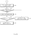
- FIGS. 2A and 2B are flowcharts illustrating a solenoid valve diagnostic method according to embodiments of the present disclosure.
- a case of diagnosing a failure in the three solenoid valves V1, V2, and V3 will be described as an example.
- the present disclosure is not limited thereto.
- the controller 150 may measure an operating current of the plurality of solenoid valves V1, V2, and V3 by using the current sensor 140 (S100). The controller 150 may measure a total current supplied to the solenoid valves V1, V2, and V3.
- the controller 150 may determine whether the measured operating current is less than the first reference current (S110). The controller 150 may determine whether the measured operating current is less than the first reference current, for example, 2.1 A.
- the controller 150 may determine that all the solenoid valves are normal (S120). When the measured operating current is greater than or equal to the first reference current, the controller 150 may determine that the solenoid valves V1, V2, and V3 are normal.
- the controller 150 may enter the first diagnostic mode (S130).
- the controller 150 may change duties of PWM control signals when entering the first diagnostic mode. For example, the controller 150 may change the duties of the PWM control signals from 100% to 90%.
- the controller 150 may determine whether the solenoid valves fail (S140).
- the controller 150 may transmit the PWM control signals having the changed duties to the solenoid valves V1, V2, and V3.
- the controller 150 may receive PWM feedback signals and may identify duties of the received PWM feedback signals. When the identified duties of the PWM feedback signals and the duties of the PWM feedback signals are inverted, that is, when the identified duties of the PWM feedback signals are equal to 10%, the controller 150 may determine a solenoid valve normal situation. When the identified duties of the PWM feedback signals are not equal to 10%, the controller 150 may determine solenoid valve failure.
- the controller 150 may determine that all the solenoid valves are normal (S120).
- the controller 150 may transition to a following check step and may measure an operating current of the plurality of solenoid valves V1, V2, and V3 by using the current sensor (S150).
- the controller 150 may determine whether the measured operating current is less than the second reference current (S160). For example, the controller 150 may determine whether the measured operating current is less than 1.4 A.
- the controller 150 may determine that the remaining solenoid valves other than one of the plurality of solenoid valves V1, V2, and V3 are normal (S170). When the measured operating current is greater than or equal to the second reference current, the controller 150 may determine that two solenoid valves among the three solenoid valves V1, V2, and V3 are normal.
- the controller 150 may enter the second diagnostic mode (S180).
- the controller 150 may determine whether the solenoid valves fail (S190). As in the first diagnostic mode, the controller 150, when entering the second diagnostic mode, may diagnose solenoid valve failure by using a PWM feedback measurement method.
- the controller 150 may determine that two solenoid valves are normal (S170).
- the controller 150 may transition to a following check step and may measure an operating current of the plurality of solenoid valves V1, V2, and V3 by using the current sensor (S200).
- the controller 150 may determine whether the measured operating current is less than the third reference current (S210).
- the controller 150 may determine that one solenoid valve is normal (S220). When the measured operating current is greater than or equal to the third reference current, the controller 150 may determine that one solenoid valve among the three solenoid valves V1, V2, and V3 is normal.
- the controller 150 may enter the third diagnostic mode (S230).
- the controller 150 may determine whether the solenoid valves fail (S240). In the third diagnostic mode, the controller 150 may diagnose solenoid valve failure by using a PWM feedback measurement method.
- the controller 150 may determine that one solenoid valve is normal (S220).
- the controller 150 may determine that all the solenoid valves fail (S250).
- whether the plurality of solenoid valves fail may be diagnosed by using the one current sensor.
- hardware and the size of the controller may be optimized, and cost savings may be achieved.
- whether the solenoid valves fail may be diagnosed through signal feedback even in event of PWM duty 100% or DC-type solenoid valve control.
Landscapes
- Engineering & Computer Science (AREA)
- General Engineering & Computer Science (AREA)
- Physics & Mathematics (AREA)
- Mechanical Engineering (AREA)
- Electromagnetism (AREA)
- General Physics & Mathematics (AREA)
- Chemical & Material Sciences (AREA)
- Transportation (AREA)
- Combustion & Propulsion (AREA)
- Life Sciences & Earth Sciences (AREA)
- Sustainable Development (AREA)
- Sustainable Energy (AREA)
- Power Engineering (AREA)
- Manufacturing & Machinery (AREA)
- Chemical Kinetics & Catalysis (AREA)
- Electrochemistry (AREA)
- General Chemical & Material Sciences (AREA)
- Magnetically Actuated Valves (AREA)
Abstract
Description
- The present disclosure relates to a solenoid valve diagnostic apparatus and method for diagnosing failure of a solenoid valve in a hydrogen storage system for driving a fuel cell system.
- A fuel cell vehicle travels using electrical energy produced by an electrochemical reaction of hydrogen and oxygen. The fuel cell vehicle includes a fuel cell that produces electrical energy and a fuel tank that stores hydrogen to be supplied to the fuel cell. The fuel tank is equipped with a solenoid valve. The solenoid valve controls input of hydrogen to the fuel tank and output of the hydrogen from the fuel tank. When a supply of hydrogen fuel to the fuel cell is limited due to failure of the solenoid valve, the amount of electricity generated is decreased, and therefore the vehicle cannot travel. In the related art, to diagnose a failure of the solenoid valve, a controller monitors, through a current sensor, a current supplied to the solenoid valve and enters a failure diagnosis mode when the corresponding current is detected to be less than or equal to a predetermined current value. However, the failure diagnosis method in the related art cannot perform diagnosis through signal feedback in the event of pulse width modulation (PWM)
duty 100% or DC-type solenoid valve control. Therefore, it is necessary to enter a diagnostic mode through the current sensor and to mount as many current sensors as valves for diagnosis of each solenoid valve. Due to this requirement, the size of the controller may be increased, and production costs may be excessive. - An aspect of the present disclosure provides a solenoid valve diagnostic apparatus and method for diagnosing failure of a plurality of solenoid valves, by using a single current sensor.
- The technical problems to be solved by the present disclosure are not limited to the aforementioned problems, and any other technical problems not mentioned herein will be clearly understood from the following description by those skilled in the art to which the present disclosure pertains.
- According to an aspect of the present disclosure, a solenoid valve diagnostic apparatus includes a plurality of solenoid valves that open or close an entrance/exit opening of a fuel tank, a current sensor that measures an operating current of the solenoid valves, and a controller that diagnoses whether the solenoid valves fail, based on the operating current measured by the current sensor.
- The controller may determine whether the measured operating current satisfies a condition for entrance to a diagnostic mode.
- The condition for entrance to the diagnostic mode may be that the measured operating current is less than reference currents differently set for respective check steps.
- The controller may change duties of PWM control signals transmitted to the solenoid valves when the controller enters the diagnostic mode and may determine a solenoid valve normal situation, when the duties of the PWM control signals and duties of PWM control signals fed back from the solenoid valves are inverted.
- The controller may maintain a current check step, when the solenoid valve normal situation is determined in the diagnostic mode.
- The controller may determine solenoid valve failure, when the duties of the PWM control signals and the duties of the PWM control signals fed back are not inverted.
- The controller may transition to a following check step, when the solenoid valve failure is determined.
- According to another aspect of the present disclosure, a solenoid valve diagnostic method includes steps of: measuring, by a current sensor, an operating current of a plurality of solenoid valves; and diagnosing, by a controller, whether the solenoid valves fail, based on the measured operating current.
- The diagnosing of whether the solenoid valves fail may include determining whether the measured operating current satisfies a condition for entrance to a diagnostic mode, entering the diagnostic mode, when the measured operating current satisfies the condition for entrance to the diagnostic mode, and determining solenoid valve failure by using a PWM feedback measurement method in the diagnostic mode.
- The determining of whether the measured operating current satisfies the condition for entrance to the diagnostic mode may include determining whether the measured operating current is less than reference currents differently set for respective check steps.
- The determining of the solenoid valve failure may include changing duties of PWM control signals transmitted to the solenoid valves, identifying duties of PWM control signals fed back from the solenoid valves, determining a solenoid valve normal situation, when the duties of the PWM control signals and the duties of the PWM control signals fed back are inverted, and determining solenoid valve failure, when the duties of the PWM control signals and the duties of the PWM control signals fed back are not inverted.
- The diagnosing of whether the solenoid valves fail may include transitioning to a following check step, when the solenoid valve failure is determined.
- The diagnosing of whether the solenoid valves fail may further include maintaining a current check step, when the solenoid valve normal situation is determined.
- The above and other objects, features and advantages of the present disclosure will be more apparent from the following detailed description taken in conjunction with the accompanying drawings:
-
FIG. 1 is a view illustrating a configuration of a solenoid valve diagnostic apparatus according to embodiments of the present disclosure; and -
FIGS. 2A and2B are flowcharts illustrating a solenoid valve diagnostic method according to embodiments of the present disclosure. - It is understood that the term "vehicle" or "vehicular" or other similar term as used herein is inclusive of motor vehicles in general such as passenger automobiles including sports utility vehicles (SUV), buses, trucks, various commercial vehicles, watercraft including a variety of boats and ships, aircraft, and the like, and includes hybrid vehicles, electric vehicles, plug-in hybrid electric vehicles, hydrogen-powered vehicles and other alternative fuel vehicles (e.g. fuels derived from resources other than petroleum). As referred to herein, a hybrid vehicle is a vehicle that has two or more sources of power, for example both gasoline-powered and electric-powered vehicles.
- The terminology used herein is for the purpose of describing particular embodiments only and is not intended to be limiting of the disclosure. As used herein, the singular forms "a," "an" and "the" are intended to include the plural forms as well, unless the context clearly indicates otherwise. It will be further understood that the terms "comprises" and/or "comprising," when used in this specification, specify the presence of stated features, integers, steps, operations, elements, and/or components, but do not preclude the presence or addition of one or more other features, integers, steps, operations, elements, components, and/or groups thereof. As used herein, the term "and/or" includes any and all combinations of one or more of the associated listed items. Throughout the specification, unless explicitly described to the contrary, the word "comprise" and variations such as "comprises" or "comprising" will be understood to imply the inclusion of stated elements but not the exclusion of any other elements. In addition, the terms "unit", "-er", "-or", and "module" described in the specification mean units for processing at least one function and operation, and can be implemented by hardware components or software components and combinations thereof.
- Further, the control logic of the present disclosure may be embodied as non-transitory computer readable media on a computer readable medium containing executable program instructions executed by a processor, controller or the like. Examples of computer readable media include, but are not limited to, ROM, RAM, compact disc (CD)-ROMs, magnetic tapes, floppy disks, flash drives, smart cards and optical data storage devices. The computer readable medium can also be distributed in network coupled computer systems so that the computer readable media is stored and executed in a distributed fashion, e.g., by a telematics server or a Controller Area Network (CAN)
- Hereinafter, some embodiments of the present disclosure will be described in detail with reference to the exemplary drawings. In adding the reference numerals to the components of each drawing, it should be noted that the identical or equivalent component is designated by the identical numeral even when they are displayed on other drawings. Further, in describing the embodiment of the present disclosure, a detailed description of well-known features or functions will be ruled out in order not to unnecessarily obscure the gist of the present disclosure.
- In describing the components of the embodiment according to the present disclosure, terms such as first, second, "A", "B", (a), (b), and the like may be used. These terms are merely intended to distinguish one component from another component, and the terms do not limit the nature, sequence or order of the components. Unless otherwise defined, all terms used herein, including technical or scientific terms, have the same meanings as those generally understood by those skilled in the art to which the present disclosure pertains. Such terms as those defined in a generally used dictionary are to be interpreted as having meanings equal to the contextual meanings in the relevant field of art, and are not to be interpreted as having ideal or excessively formal meanings unless clearly defined as having such in the present application.
- Embodiments of the present disclosure relate to a technology for diagnosing whether a solenoid valve in a hydrogen storage system for driving a fuel cell system fails.
-
FIG. 1 is a view illustrating a configuration of a solenoid valvediagnostic apparatus 100 according to embodiments of the present disclosure. - Referring to
FIG. 1 , the solenoid valvediagnostic apparatus 100 may include afuel tank 110, afuel cell stack 120, a plurality of valves 130 (preferably, solenoid valves), acurrent sensor 140, and acontroller 150. - The
fuel tank 110 is a fuel supply apparatus that stores hydrogen to be supplied to thefuel cell stack 120. The fuel tank (or a plurality of fuel tanks) 110 may be equipped in a vehicle. In this embodiment, thefuel tank 110 is exemplified by threefuel tanks more fuel tanks 110 may be equipped in the vehicle. - The
fuel cell stack 120 may produce electrical energy by an electrochemical reaction of hydrogen and oxygen. Thefuel cell stack 120 may receive hydrogen from thefuel tank 110 and may produce electricity. The electrical energy generated by thefuel cell stack 120 may be used as energy for driving an electric motor (not illustrated). - The
valves 130 may open or close supply passages of hydrogen fuel that is supplied from thefuel tank 110 to thefuel cell stack 120. Thevalves 130 may be opened or closed depending on control signals input from thecontroller 150 to supply hydrogen stored in thefuel tank 110 to thefuel cell stack 120 or interrupt the supply of the hydrogen to thefuel cell stack 120. Thevalves 130 may be mounted outside or inside thefuel tank 110. Thevalves 130 may include a first solenoid valve V1, a second solenoid valve V2, and a third solenoid valve V3 mounted outside or inside thefirst fuel tank 111, thesecond fuel tank 112, and thethird fuel tank 113, respectively. The number ofvalves 130 may be increased with an increase in the number offuel tanks 110. - The
current sensor 140 may measure an operating current (a driving current) of thevalves 130. Thecurrent sensor 140 may measure a total current supplied to the first solenoid valve V1, the second solenoid valve V2, and the third solenoid valve V3. In this embodiment, thecurrent sensor 140 is described as being located outside thecontroller 150. However, without being limited thereto, thecurrent sensor 140 may be configured to be located inside thecontroller 150. - The
controller 150 may be electrically connected with thevalves 130 and thecurrent sensor 140. Thecontroller 150 may include a processor. The processor may control overall operation of thecontroller 150 and may be a central processing unit (CPU), a microcontroller, and/or a microprocessor. Thecontroller 150 may further include a memory inside and/or outside thecontroller 150. The memory may be a non-transitory storage medium that stores instructions executed by the processor. The memory may be a flash memory, a hard disk drive, a random access memory (RAM), a read only memory (ROM), a programmable read only memory (PROM), an electrically erasable and programmable ROM (EEPROM), an erasable and programmable ROM (EPROM), and/or a register. - The
controller 150 may control opening/shutting of thevalves 130 by using pulse width modulation (PWM) control. Thecontroller 150 may adjust duties of PWM control signals supplied to thevalves 130. - The
controller 150 may detect the operating current of thevalves 130 by using thecurrent sensor 140. Thecontroller 150 may determine whether to enter a diagnostic mode for diagnosis of failure of the solenoid valves, based on the detected operating current. Thecontroller 150 may determine whether to transition to a check step, based on an outcome of diagnosis in the diagnostic mode. Thecontroller 150 may maintain the current check step when a solenoid valve normal situation is diagnosed and may transition to a following check step when solenoid valve failure is diagnosed. The number of check steps may be determined based on the number of solenoid valves, and conditions for entrance to diagnostic modes, that is, reference currents may be differently set for the respective check steps. For example, in a case where the number of solenoid valves is N, the check steps may be divided into a first check step of checking states of the solenoid valves when N solenoid valves are normal, a second check step of checking states of the solenoid valves when N-1 solenoid valves are normal, ..., and an Nth check step of checking states of the solenoid valves when one solenoid valve is normal. - When operating currents detected in the respective check steps satisfy the conditions for entrance to the diagnostic modes, the
controller 150 may enter the diagnostic modes and may diagnose thevalves 130. At this time, thecontroller 150 may determine whether the solenoid valves fail, by using a PWM feedback measurement method. Thecontroller 150, when entering the diagnostic modes, may change PWM duties of control signals transmitted to thevalves 130. For example, thecontroller 150 may change the duties of the PWM control signals from 100% to 90%. Thecontroller 150 may transmit the PWM control signals having the changed duties to thevalves 130 and may receive PWM control signals (that is, PWM feedback signals) fed back from thevalves 130. Thecontroller 150 may identify duties of the PWM feedback signals and may determine whether the solenoid valves fail, based on the identified duties. Thecontroller 150 may determine whether the duties of the PWM control signals and the duties of the PWM feedback signals are inverted. When it is determined that the duties of the PWM control signals and the duties of the PWM feedback signals are inverted, thecontroller 150 may determine a solenoid valve normal situation. When it is determined that the duties of the PWM control signals and the duties of the PWM feedback signals are not inverted, thecontroller 150 may determine solenoid valve failure. - Hereinafter, a case of diagnosing a failure in the three solenoid valves V1, V2, and V3 will be described as an example.
- When the three solenoid valves V1, V2, and V3 are normal, the
controller 150 may operate in a first check step. In the first check step, thecontroller 150 may detect (measure) an operating current of the three solenoid valves V1, V2, and V3 by using thecurrent sensor 140. Thecontroller 150 may determine whether the detected operating current is greater than or equal to a first reference current (e.g., 2.1 A). When the detected operating current is greater than or equal to the first reference current, thecontroller 150 may determine a solenoid valve normal situation. That is, thecontroller 150 may determine that all the solenoid valves V1, V2, and V3 are normal. - When the detected operating current is less than the first reference current, the controller may enter a first diagnostic mode. The
controller 150, when entering the first diagnostic mode, may change PWM duties to 90% and may transmit PWM control signals having the changed duties to the solenoid valves V1, V2, and V3. Thecontroller 150 may receive PWM feedback signals, may identify duties of the received PWM feedback signals, and may determine whether the solenoid valves fail. When the duties of the received PWM feedback signals are equal to 10%, thecontroller 150 may determine a solenoid valve normal situation. When the duties of the received PWM feedback signals are not equal to 10%, thecontroller 150 may determine solenoid valve failure. - When the solenoid valve normal situation is determined in the first diagnostic mode, the
controller 150 may determine that all the solenoid valves V1, V2, and V3 are normal. When the solenoid valve failure is determined in the first diagnostic mode, thecontroller 150 may transition to a following check step, that is, a second check step. - In the second check step, the
controller 150 may detect an operating current of the solenoid valves V1, V2, and V3 by using thecurrent sensor 140 and may determine whether the detected operating current is greater than or equal to a second reference current (e.g., 1.4A). When the detected operating current is greater than or equal to the second reference current, thecontroller 150 may determine that two solenoid valves are normal. - When the detected operating current is less than the second reference current, the controller may enter a second diagnostic mode. As in the first diagnostic mode, the
controller 150, when entering the second diagnostic mode, may diagnose solenoid valve failure by using a PWM feedback measurement method. When a solenoid valve normal situation is diagnosed in the second diagnostic mode, thecontroller 150 may determine that two solenoid valves are normal. When solenoid valve failure is diagnosed in the second diagnostic mode, thecontroller 150 may transition to a following check step, that is, a third check step. - In the third check step, the
controller 150 may measure an operating current of the solenoid valves V1, V2, and V3 by using thecurrent sensor 140. Thecontroller 150 may determine whether the measured operating current is greater than or equal to a third reference current (e.g., 0.7 A). When the measured operating current is greater than or equal to the third reference current, thecontroller 150 may determine that one solenoid valve is normal. When the measured operating current is less than the third reference current, thecontroller 150 may enter a third diagnostic mode. Even in the third diagnostic mode, thecontroller 150 may diagnose solenoid valve failure by using a PWM feedback measurement method. When a solenoid valve normal situation is diagnosed in the third diagnostic mode, thecontroller 150 may determine that one solenoid valve is normal. When solenoid valve failure is diagnosed, thecontroller 150 may determine that all the solenoid valves fail. -
FIGS. 2A and2B are flowcharts illustrating a solenoid valve diagnostic method according to embodiments of the present disclosure. In this embodiment, for a better understanding, a case of diagnosing a failure in the three solenoid valves V1, V2, and V3 will be described as an example. However, the present disclosure is not limited thereto. - The
controller 150 may measure an operating current of the plurality of solenoid valves V1, V2, and V3 by using the current sensor 140 (S100). Thecontroller 150 may measure a total current supplied to the solenoid valves V1, V2, and V3. - The
controller 150 may determine whether the measured operating current is less than the first reference current (S110). Thecontroller 150 may determine whether the measured operating current is less than the first reference current, for example, 2.1 A. - When the measured operating current is not less than the first reference current, the
controller 150 may determine that all the solenoid valves are normal (S120). When the measured operating current is greater than or equal to the first reference current, thecontroller 150 may determine that the solenoid valves V1, V2, and V3 are normal. - When the measured operating current is less than the first reference current, the
controller 150 may enter the first diagnostic mode (S130). Thecontroller 150 may change duties of PWM control signals when entering the first diagnostic mode. For example, thecontroller 150 may change the duties of the PWM control signals from 100% to 90%. - In the first diagnostic mode, the
controller 150 may determine whether the solenoid valves fail (S140). Thecontroller 150 may transmit the PWM control signals having the changed duties to the solenoid valves V1, V2, and V3. Thecontroller 150 may receive PWM feedback signals and may identify duties of the received PWM feedback signals. When the identified duties of the PWM feedback signals and the duties of the PWM feedback signals are inverted, that is, when the identified duties of the PWM feedback signals are equal to 10%, thecontroller 150 may determine a solenoid valve normal situation. When the identified duties of the PWM feedback signals are not equal to 10%, thecontroller 150 may determine solenoid valve failure. - When the solenoid valve normal situation is determined in the first diagnostic mode, the
controller 150 may determine that all the solenoid valves are normal (S120). - When the solenoid valve failure is determined in the first diagnostic mode, the
controller 150 may transition to a following check step and may measure an operating current of the plurality of solenoid valves V1, V2, and V3 by using the current sensor (S150). - The
controller 150 may determine whether the measured operating current is less than the second reference current (S160). For example, thecontroller 150 may determine whether the measured operating current is less than 1.4 A. - When the measured operating current is not less than the second reference current, the
controller 150 may determine that the remaining solenoid valves other than one of the plurality of solenoid valves V1, V2, and V3 are normal (S170). When the measured operating current is greater than or equal to the second reference current, thecontroller 150 may determine that two solenoid valves among the three solenoid valves V1, V2, and V3 are normal. - When the measured operating current is less than the second reference current, the
controller 150 may enter the second diagnostic mode (S180). - In the second diagnostic mode, the
controller 150 may determine whether the solenoid valves fail (S190). As in the first diagnostic mode, thecontroller 150, when entering the second diagnostic mode, may diagnose solenoid valve failure by using a PWM feedback measurement method. - When a solenoid valve normal situation is determined in the second diagnostic mode, the
controller 150 may determine that two solenoid valves are normal (S170). - When solenoid valve failure is determined in the second diagnostic mode, the
controller 150 may transition to a following check step and may measure an operating current of the plurality of solenoid valves V1, V2, and V3 by using the current sensor (S200). - The
controller 150 may determine whether the measured operating current is less than the third reference current (S210). - When the measured operating current is not less than the third reference current, the
controller 150 may determine that one solenoid valve is normal (S220). When the measured operating current is greater than or equal to the third reference current, thecontroller 150 may determine that one solenoid valve among the three solenoid valves V1, V2, and V3 is normal. - When the measured operating current is less than the third reference current, the
controller 150 may enter the third diagnostic mode (S230). - In the third diagnostic mode, the
controller 150 may determine whether the solenoid valves fail (S240). In the third diagnostic mode, thecontroller 150 may diagnose solenoid valve failure by using a PWM feedback measurement method. - When a solenoid valve normal situation is determined in the third diagnostic mode, the
controller 150 may determine that one solenoid valve is normal (S220). - When solenoid valve failure is determined in the third diagnostic mode, the
controller 150 may determine that all the solenoid valves fail (S250). - According to the present disclosure, whether the plurality of solenoid valves fail may be diagnosed by using the one current sensor. Thus, hardware and the size of the controller may be optimized, and cost savings may be achieved.
- According to the present disclosure, whether the solenoid valves fail may be diagnosed through signal feedback even in event of
PWM duty 100% or DC-type solenoid valve control. - Hereinabove, although the present disclosure has been described with reference to exemplary embodiments and the accompanying drawings, the present disclosure is not limited thereto, but may be variously modified and altered by those skilled in the art to which the present disclosure pertains without departing from the spirit and scope of the present disclosure claimed in the following claims. Therefore, the exemplary embodiments of the present disclosure are provided to explain the spirit and scope of the present disclosure, but not to limit them, so that the spirit and scope of the present disclosure is not limited by the embodiments. The scope of the present disclosure should be construed on the basis of the accompanying claims, and all the technical ideas within the scope equivalent to the claims should be included in the scope of the present disclosure.
- 110, 111, 112, 113: FUEL TANK
- 120: FUEL CELL STACK
- 130: VALVES
- 140: CURRENT SENSOR
- 150: CONTROLLER
Claims (13)
- A solenoid valve diagnostic apparatus, comprising:a plurality of solenoid valves each configured to open or close an entrance/exit opening of a fuel tank;a current sensor configured to measure an operating current of the solenoid valves; anda controller configured to diagnose whether the solenoid valves fail, based on the operating current measured by the current sensor.
- The solenoid valve diagnostic apparatus of claim 1, wherein the controller determines whether the measured operating current satisfies a condition for entrance to a diagnostic mode.
- The solenoid valve diagnostic apparatus of claim 2, wherein the condition for entrance to the diagnostic mode is that the measured operating current is less than reference currents differently set for respective check steps.
- The solenoid valve diagnostic apparatus of claim 2, wherein the controller:changes duties of PWM control signals transmitted to the solenoid valves when the controller enters the diagnostic mode; anddetermines a solenoid valve normal situation, when the duties of the PWM control signals and duties of PWM control signals fed back from the solenoid valves are inverted.
- The solenoid valve diagnostic apparatus of claim 4, wherein the controller maintains a current check step, when the solenoid valve normal situation is determined in the diagnostic mode.
- The solenoid valve diagnostic apparatus of claim 4, wherein the controller determines solenoid valve failure, when the duties of the PWM control signals and the duties of the PWM control signals fed back are not inverted.
- The solenoid valve diagnostic apparatus of claim 6, wherein the controller transitions to a following check step, when the solenoid valve failure is determined.
- A solenoid valve diagnostic method, comprising the steps of:measuring, by a current sensor, an operating current of a plurality of solenoid valves; anddiagnosing, by a controller, whether the solenoid valves fail, based on the measured operating current.
- The solenoid valve diagnostic method of claim 8, wherein diagnosing whether the solenoid valves fail includes:determining whether the measured operating current satisfies a condition for entrance to a diagnostic mode;entering the diagnostic mode, when the measured operating current satisfies the condition for entrance to the diagnostic mode; anddetermining solenoid valve failure by using a PWM feedback measurement method in the diagnostic mode.
- The solenoid valve diagnostic method of claim 9, wherein determining whether the measured operating current satisfies the condition for entrance to the diagnostic mode includes:
determining whether the measured operating current is less than reference currents differently set for respective check steps. - The solenoid valve diagnostic method of claim 9, wherein determining the solenoid valve failure includes:changing duties of PWM control signals transmitted to the solenoid valves;identifying duties of PWM control signals fed back from the solenoid valves;determining a solenoid valve normal situation, when the duties of the PWM control signals and the duties of the PWM control signals fed back are inverted; anddetermining solenoid valve failure, when the duties of the PWM control signals and the duties of the PWM control signals fed back are not inverted.
- The solenoid valve diagnostic method of claim 11, wherein diagnosing whether the solenoid valves fail includes:
transitioning to a following check step, when the solenoid valve failure is determined. - The solenoid valve diagnostic method of claim 11, wherein diagnosing whether the solenoid valves fail further includes:
maintaining a current check step, when the solenoid valve normal situation is determined.
Applications Claiming Priority (1)
| Application Number | Priority Date | Filing Date | Title |
|---|---|---|---|
| KR1020210001591A KR102842950B1 (en) | 2021-01-06 | 2021-01-06 | Solenoid valve diagnostic apparatus and method |
Publications (1)
| Publication Number | Publication Date |
|---|---|
| EP4027156A1 true EP4027156A1 (en) | 2022-07-13 |
Family
ID=76942874
Family Applications (1)
| Application Number | Title | Priority Date | Filing Date |
|---|---|---|---|
| EP21185787.5A Pending EP4027156A1 (en) | 2021-01-06 | 2021-07-15 | Solenoid valve diagnostic apparatus and method |
Country Status (4)
| Country | Link |
|---|---|
| US (1) | US12123518B2 (en) |
| EP (1) | EP4027156A1 (en) |
| KR (1) | KR102842950B1 (en) |
| CN (1) | CN114720791B (en) |
Families Citing this family (7)
| Publication number | Priority date | Publication date | Assignee | Title |
|---|---|---|---|---|
| US12259065B2 (en) * | 2021-09-03 | 2025-03-25 | Levitronix Gmbh | Pinch valve system |
| KR20230164444A (en) * | 2022-05-25 | 2023-12-04 | 현대자동차주식회사 | Apparatus for detecting opening and closing of a valve in fuel cell system and method thereof |
| DE102022209693A1 (en) * | 2022-09-15 | 2024-03-21 | Robert Bosch Gesellschaft mit beschränkter Haftung | Method and system for detecting a malfunction in a fuel cell system |
| WO2024056212A1 (en) * | 2022-09-15 | 2024-03-21 | Robert Bosch Gmbh | Method for detecting a malfunction, tank system, computer program product and storage means |
| CN115855480B (en) * | 2023-01-06 | 2026-04-24 | 一汽解放汽车有限公司 | A method, apparatus, device, and storage medium for diagnosing faults in a solenoid valve. |
| CN116335856B (en) * | 2023-04-19 | 2025-06-27 | 中国第一汽车股份有限公司 | Carbon canister solenoid valve fault detection method, device, electronic equipment and storage medium |
| CN118962419B (en) * | 2024-07-16 | 2025-09-23 | 东风汽车集团股份有限公司 | Hybrid vehicle switch solenoid valve self-test method, device, equipment and storage medium |
Citations (3)
| Publication number | Priority date | Publication date | Assignee | Title |
|---|---|---|---|---|
| US10378501B2 (en) * | 2017-12-07 | 2019-08-13 | GM Global Technology Operations LLC | Systems and method for performing prognosis of fuel delivery systems using solenoid current feedback |
| US10443530B1 (en) * | 2018-05-22 | 2019-10-15 | Gm Global Technology Operations Llc. | System with solenoid assembly and method of fault diagnosis and isolation |
| KR20200071175A (en) * | 2018-12-10 | 2020-06-19 | 현대오트론 주식회사 | Diagnosis apparatus and method |
Family Cites Families (8)
| Publication number | Priority date | Publication date | Assignee | Title |
|---|---|---|---|---|
| JPH09196991A (en) * | 1996-01-17 | 1997-07-31 | Naldec Kk | Failure detecting circuit and its detection |
| GB2367962B (en) * | 2000-10-14 | 2004-07-21 | Trw Ltd | Multiple channel solenoid current monitor |
| US6815101B2 (en) * | 2001-07-25 | 2004-11-09 | Ballard Power Systems Inc. | Fuel cell ambient environment monitoring and control apparatus and method |
| KR100394683B1 (en) | 2001-10-29 | 2003-08-14 | 현대자동차주식회사 | Solenoid valve force device |
| JP4415779B2 (en) * | 2004-03-25 | 2010-02-17 | 株式会社デンソー | Drive device for secondary air introduction system |
| KR20060031241A (en) * | 2004-10-08 | 2006-04-12 | 주식회사 만도 | Fault diagnosis method of proportional solenoid drive |
| CN103375586B (en) * | 2012-04-13 | 2015-04-08 | 广州汽车集团股份有限公司 | Method for discriminating neutral gear on basis of electronic neutral gear sensor |
| JP2019091868A (en) * | 2017-11-17 | 2019-06-13 | Kyb株式会社 | Control device and damping device for railway vehicle |
-
2021
- 2021-01-06 KR KR1020210001591A patent/KR102842950B1/en active Active
- 2021-07-13 US US17/374,053 patent/US12123518B2/en active Active
- 2021-07-15 EP EP21185787.5A patent/EP4027156A1/en active Pending
- 2021-07-27 CN CN202110848285.4A patent/CN114720791B/en active Active
Patent Citations (3)
| Publication number | Priority date | Publication date | Assignee | Title |
|---|---|---|---|---|
| US10378501B2 (en) * | 2017-12-07 | 2019-08-13 | GM Global Technology Operations LLC | Systems and method for performing prognosis of fuel delivery systems using solenoid current feedback |
| US10443530B1 (en) * | 2018-05-22 | 2019-10-15 | Gm Global Technology Operations Llc. | System with solenoid assembly and method of fault diagnosis and isolation |
| KR20200071175A (en) * | 2018-12-10 | 2020-06-19 | 현대오트론 주식회사 | Diagnosis apparatus and method |
Also Published As
| Publication number | Publication date |
|---|---|
| US20220213978A1 (en) | 2022-07-07 |
| KR102842950B1 (en) | 2025-08-06 |
| KR20220099400A (en) | 2022-07-13 |
| CN114720791A (en) | 2022-07-08 |
| US12123518B2 (en) | 2024-10-22 |
| CN114720791B (en) | 2026-04-07 |
Similar Documents
| Publication | Publication Date | Title |
|---|---|---|
| US12123518B2 (en) | Solenoid valve diagnostic apparatus and method | |
| US10183664B2 (en) | Vehicle system, battery system and control method thereof | |
| US9171407B2 (en) | System and method of detecting fuse disconnection of DC-DC converter | |
| US10247768B2 (en) | System and method for measuring insulation resistance of fuel cell vehicle | |
| US10322644B2 (en) | Apparatus and method for controlling cooling fan of battery of vehicle | |
| US10000139B2 (en) | Safety system of fuel cell vehicle and control method for the same | |
| US10168183B2 (en) | Method and system for determining failure within resolver | |
| US9067505B2 (en) | System and method for cell balancing of battery pack | |
| US20230187666A1 (en) | Hydrogen leak sensing device and method for fuel cell vehicle | |
| US9735452B2 (en) | Apparatus and method for monitoring component breakdown of battery system | |
| US20190190043A1 (en) | Fuel cell failure diagnostic apparatus and method thereof | |
| US20210033645A1 (en) | Device for detecting current leakage and current leakage detection system including the same | |
| US10388973B2 (en) | Fuel cell stack diagnostic system and diagnostic method thereof | |
| US10293701B2 (en) | Control method and system of low-voltage DC-DC converter for hybrid vehicle | |
| US20160156084A1 (en) | Apparatus and method for controlling converter | |
| US11312263B2 (en) | Method and system for controlling operation of fuel cell of fuel cell vehicle | |
| US12523562B2 (en) | Apparatus and method for monitoring hydrogen storage system of vehicle | |
| US20150176719A1 (en) | Method and apparatus for detecting opening and closing of pilot operated solenoid valve for hydrogen tank | |
| US20200180603A1 (en) | Charging control method and system for battery of vehicle | |
| CN112519636B (en) | Driving control apparatus and driving control method for fuel cell vehicle | |
| US20250206244A1 (en) | Method for converting redundancy power and system for the same | |
| US11565608B2 (en) | System and method for controlling low voltage DC converter of fuel cell vehicle | |
| US11747404B2 (en) | Apparatus and method for detecting thermal runaway of battery for electric vehicle | |
| US11658318B2 (en) | Control method and control system for fuel cell stop mode | |
| US10971746B2 (en) | Fuel cell system for modulating offset of hydrogen pressure sensor and method for modulating offset of hydrogen pressure sensor |
Legal Events
| Date | Code | Title | Description |
|---|---|---|---|
| PUAI | Public reference made under article 153(3) epc to a published international application that has entered the european phase |
Free format text: ORIGINAL CODE: 0009012 |
|
| STAA | Information on the status of an ep patent application or granted ep patent |
Free format text: STATUS: THE APPLICATION HAS BEEN PUBLISHED |
|
| AK | Designated contracting states |
Kind code of ref document: A1 Designated state(s): AL AT BE BG CH CY CZ DE DK EE ES FI FR GB GR HR HU IE IS IT LI LT LU LV MC MK MT NL NO PL PT RO RS SE SI SK SM TR |
|
| STAA | Information on the status of an ep patent application or granted ep patent |
Free format text: STATUS: REQUEST FOR EXAMINATION WAS MADE |
|
| 17P | Request for examination filed |
Effective date: 20230113 |
|
| RBV | Designated contracting states (corrected) |
Designated state(s): AL AT BE BG CH CY CZ DE DK EE ES FI FR GB GR HR HU IE IS IT LI LT LU LV MC MK MT NL NO PL PT RO RS SE SI SK SM TR |
|
| P01 | Opt-out of the competence of the unified patent court (upc) registered |
Effective date: 20230420 |
|
| STAA | Information on the status of an ep patent application or granted ep patent |
Free format text: STATUS: EXAMINATION IS IN PROGRESS |
|
| 17Q | First examination report despatched |
Effective date: 20240708 |
|
| REG | Reference to a national code |
Ref country code: DE Ref legal event code: R079 Free format text: PREVIOUS MAIN CLASS: G01R0031327000 Ipc: F16K0037000000 |