EP4027125A1 - Pressure sensor - Google Patents
Pressure sensor Download PDFInfo
- Publication number
- EP4027125A1 EP4027125A1 EP20861328.1A EP20861328A EP4027125A1 EP 4027125 A1 EP4027125 A1 EP 4027125A1 EP 20861328 A EP20861328 A EP 20861328A EP 4027125 A1 EP4027125 A1 EP 4027125A1
- Authority
- EP
- European Patent Office
- Prior art keywords
- base material
- hole
- pressure sensor
- sensing portion
- signal line
- Prior art date
- Legal status (The legal status is an assumption and is not a legal conclusion. Google has not performed a legal analysis and makes no representation as to the accuracy of the status listed.)
- Granted
Links
Images



Classifications
-
- G—PHYSICS
- G01—MEASURING; TESTING
- G01L—MEASURING FORCE, STRESS, TORQUE, WORK, MECHANICAL POWER, MECHANICAL EFFICIENCY, OR FLUID PRESSURE
- G01L1/00—Measuring force or stress, in general
- G01L1/14—Measuring force or stress, in general by measuring variations in capacitance or inductance of electrical elements, e.g. by measuring variations of frequency of electrical oscillators
-
- G—PHYSICS
- G01—MEASURING; TESTING
- G01L—MEASURING FORCE, STRESS, TORQUE, WORK, MECHANICAL POWER, MECHANICAL EFFICIENCY, OR FLUID PRESSURE
- G01L1/00—Measuring force or stress, in general
- G01L1/20—Measuring force or stress, in general by measuring variations in ohmic resistance of solid materials or of electrically-conductive fluids; by making use of electrokinetic cells, i.e. liquid-containing cells wherein an electrical potential is produced or varied upon the application of stress
-
- G—PHYSICS
- G01—MEASURING; TESTING
- G01L—MEASURING FORCE, STRESS, TORQUE, WORK, MECHANICAL POWER, MECHANICAL EFFICIENCY, OR FLUID PRESSURE
- G01L1/00—Measuring force or stress, in general
- G01L1/20—Measuring force or stress, in general by measuring variations in ohmic resistance of solid materials or of electrically-conductive fluids; by making use of electrokinetic cells, i.e. liquid-containing cells wherein an electrical potential is produced or varied upon the application of stress
- G01L1/205—Measuring force or stress, in general by measuring variations in ohmic resistance of solid materials or of electrically-conductive fluids; by making use of electrokinetic cells, i.e. liquid-containing cells wherein an electrical potential is produced or varied upon the application of stress using distributed sensing elements
-
- G—PHYSICS
- G01—MEASURING; TESTING
- G01L—MEASURING FORCE, STRESS, TORQUE, WORK, MECHANICAL POWER, MECHANICAL EFFICIENCY, OR FLUID PRESSURE
- G01L1/00—Measuring force or stress, in general
- G01L1/20—Measuring force or stress, in general by measuring variations in ohmic resistance of solid materials or of electrically-conductive fluids; by making use of electrokinetic cells, i.e. liquid-containing cells wherein an electrical potential is produced or varied upon the application of stress
- G01L1/22—Measuring force or stress, in general by measuring variations in ohmic resistance of solid materials or of electrically-conductive fluids; by making use of electrokinetic cells, i.e. liquid-containing cells wherein an electrical potential is produced or varied upon the application of stress using resistance strain gauges
-
- G—PHYSICS
- G01—MEASURING; TESTING
- G01L—MEASURING FORCE, STRESS, TORQUE, WORK, MECHANICAL POWER, MECHANICAL EFFICIENCY, OR FLUID PRESSURE
- G01L1/00—Measuring force or stress, in general
- G01L1/20—Measuring force or stress, in general by measuring variations in ohmic resistance of solid materials or of electrically-conductive fluids; by making use of electrokinetic cells, i.e. liquid-containing cells wherein an electrical potential is produced or varied upon the application of stress
- G01L1/22—Measuring force or stress, in general by measuring variations in ohmic resistance of solid materials or of electrically-conductive fluids; by making use of electrokinetic cells, i.e. liquid-containing cells wherein an electrical potential is produced or varied upon the application of stress using resistance strain gauges
- G01L1/2287—Measuring force or stress, in general by measuring variations in ohmic resistance of solid materials or of electrically-conductive fluids; by making use of electrokinetic cells, i.e. liquid-containing cells wherein an electrical potential is produced or varied upon the application of stress using resistance strain gauges constructional details of the strain gauges
-
- G—PHYSICS
- G01—MEASURING; TESTING
- G01L—MEASURING FORCE, STRESS, TORQUE, WORK, MECHANICAL POWER, MECHANICAL EFFICIENCY, OR FLUID PRESSURE
- G01L9/00—Measuring steady of quasi-steady pressure of fluid or fluent solid material by electric or magnetic pressure-sensitive elements; Transmitting or indicating the displacement of mechanical pressure-sensitive elements, used to measure the steady or quasi-steady pressure of a fluid or fluent solid material, by electric or magnetic means
- G01L9/02—Measuring steady of quasi-steady pressure of fluid or fluent solid material by electric or magnetic pressure-sensitive elements; Transmitting or indicating the displacement of mechanical pressure-sensitive elements, used to measure the steady or quasi-steady pressure of a fluid or fluent solid material, by electric or magnetic means by making use of variations in ohmic resistance, e.g. of potentiometers, electric circuits therefor, e.g. bridges, amplifiers or signal conditioning
-
- G—PHYSICS
- G01—MEASURING; TESTING
- G01L—MEASURING FORCE, STRESS, TORQUE, WORK, MECHANICAL POWER, MECHANICAL EFFICIENCY, OR FLUID PRESSURE
- G01L9/00—Measuring steady of quasi-steady pressure of fluid or fluent solid material by electric or magnetic pressure-sensitive elements; Transmitting or indicating the displacement of mechanical pressure-sensitive elements, used to measure the steady or quasi-steady pressure of a fluid or fluent solid material, by electric or magnetic means
- G01L9/12—Measuring steady of quasi-steady pressure of fluid or fluent solid material by electric or magnetic pressure-sensitive elements; Transmitting or indicating the displacement of mechanical pressure-sensitive elements, used to measure the steady or quasi-steady pressure of a fluid or fluent solid material, by electric or magnetic means by making use of variations in capacitance, i.e. electric circuits therefor
-
- B—PERFORMING OPERATIONS; TRANSPORTING
- B81—MICROSTRUCTURAL TECHNOLOGY
- B81B—MICROSTRUCTURAL DEVICES OR SYSTEMS, e.g. MICROMECHANICAL DEVICES
- B81B2201/00—Specific applications of microelectromechanical systems
- B81B2201/02—Sensors
- B81B2201/0264—Pressure sensors
Definitions
- An embodiment of the present invention relates to a pressure sensor.
- Conventional pressure sensors are coupled a general substrate or base material as a thin film in a plane so as to respond to contraction and relaxation of the base material depending on deformation thereof in order to sense the degree of bending or deformation of the base material.
- Patent Document 1 KR 101301277 B1 1
- a pressure sensor includes a base material, a through-hole formed through the base material so as to extend from an upper surface to a lower surface thereof, and a conductive thread sensor including conductive thread extending through the through-hole.
- the conductive thread sensor may include a first signal line extending from one side of the base material, a sensing portion extending from the first signal line so as to extend from one surface of the base material to the other surface of the base material via an inside of the through-hole, and a second signal line extending from the sensing portion so as to extend to the other side of the base material.
- the sensing portion may be formed in an inner space of the through-hole so as to be bent upwards and downwards a plurality of times, and the inner space of the through-hole and a space between the bent parts of the sensing portion bent the plurality of times may be filled with an insulating material configured to elastically support an upper part and a lower part of the through-hole.
- an interior of the through-hole may be filled with conductive paste, the conductive paste being coupled to the sensing portion and elastically supported in an upward-downward direction of the base material.
- the pressure sensor may further include a bump coupled to the one surface of the base material so as to cover the through-hole, the bump being convex upwards.
- the sensing portion may be formed so as to have higher resistance than the first signal line and the second signal line.
- the sensing portion may be made of an insulating material.
- a pressure sensor includes a base material, a first through-hole and a second through-hole formed on one surface of the base material, the first through-hole and the second through-hole being formed through the base material so as to extend from an upper surface to a lower surface thereof, and a conductive thread sensor, the conductive thread sensor including a first signal line extending from one side of the base material, a sensing portion extending from the first signal line so as to continuously extend from the one surface of the base material via the first through-hole and the second through-hole, the sensing portion being coupled to the first through-hole and the second through-hole, and a second signal line extending from the sensing portion so as to extend to the other side of the base material.
- the sensing portion may extend through the first through-hole and the second through-hole and may be formed so as to be wound a plurality of times between the first through-hole and the second through-hole.
- an interior of each of the first through-hole and the second through-hole may be filled with conductive paste, the conductive paste being coupled to the sensing portion and configured to elastically support an upper part and a lower part of the sensing portion.
- the pressure sensor may further include a first bump coupled to the one surface of the base material so as to cover the first through-hole, the first bump being formed so as to be convex upwards, and a second bump coupled to the one surface of the base material so as to cover the second through-hole, the second bump being formed so as to be convex upwards.
- the sensing portion may be formed so as to have higher resistance than the first signal line and the second signal line.
- the sensing portion may be made of an insulating material.
- a pressure sensor includes a base material, a plurality of through-holes formed on one surface of the base material, the plurality of through-holes being formed through the base material so as to extend from an upper surface to a lower surface thereof, and a conductive thread sensor, the conductive thread sensor including a first signal line extending from one side of the base material, a sensing portion extending from the first signal line so as to continuously extend from the one surface of the base material via the plurality of through-holes, the sensing portion being coupled to the plurality of through-holes, and a second signal line extending from the sensing portion so as to extend to the other side of the base material.
- the sensing portion may continuously extend through the plurality of through-holes, may be coupled to the plurality of through-holes, and may be coupled so as to be wound a plurality of times between adjacent ones of the through-holes.
- an interior of each of the plurality of through-holes may be filled with conductive paste, the conductive paste being coupled to the sensing portion and elastically supported in an upward-downward direction of the base material.
- the pressure sensor may further include a plurality of bumps coupled to the one surface of the base material so as to cover the plurality of through-holes, each of the plurality of bumps being formed so as to be convex upwards.
- the sensing portion may be formed so as to have higher resistance than the first signal line and the second signal line.
- the sensing portion may be made of an insulating material.
- a pressure sensor includes a base material, a through-hole formed on one surface of the base material, the through-hole being formed through the base material so as to extend from an upper surface to a lower surface thereof, a first signal line extending from one side of the base material, a first electrode portion extending from the first signal line so as to extend through the through-hole from the one surface of the base material and to be coupled to one side of an inner circumferential surface of the through-hole, a second signal line extending from the other side of the base material, a second electrode portion extending from the second signal line so as to extend through the through-hole from the one surface of the base material and to be coupled to the other side of the inner circumferential surface of the through-hole, the second electrode portion being spaced apart from the first electrode portion while facing the first electrode portion, and a dielectric substance, with which a space between the first electrode portion and the second electrode portion is filled.
- a pressure sensor is implemented through structural coupling between conductive thread and a base material, whereby it is possible to achieve application to a variety of recent wearable flexible materials, to effectively respond to deformation of a base material itself, and to effectively increase the degree of design freedom.
- a point structure for partial pressure sensing as a bump, in addition to implementation of the pressure sensor through conductive thread, whereby it is possible to transfer overall pressure to an effective sensing point, and therefore it is possible to more effectively improve accuracy and reliability in pressure sensing.
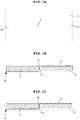
- FIGs. 1A, 1B, and 1C are respectively a plan view, a sectional view, and another sectional view of a pressure sensor according to a first embodiment of the present invention
- FIG. 2 is a sectional view of a modification of the pressure sensor according to the first embodiment of the present invention
- FIG. 3 is a sectional view of another modification of the pressure sensor according to the first embodiment of the present invention
- FIG. 4 is a sectional view of an example in which a bump 50 is coupled to the pressure sensor according to the first embodiment of the present invention.
- the pressure sensor according to the first embodiment of the present invention includes a base material 10, a through-hole 11 formed through the base material 10 so as to extend from the upper surface to the lower surface thereof, and a conductive thread sensor 20, the conductive thread sensor including a first signal line 21 extending from one side of the base material 10, a sensing portion 22 extending from the first signal line 21 so as to extend from one surface of the base material 10 to the other surface of the base material 10 via the inside of the through-hole 11, and a second signal line 23 extending from the sensing portion 22 so as to extend to the other side of the base material 10.
- the through-hole 11 is formed in the base material 10, and the sensing portion 22 is coupled to the through-hole 11 in an upward-downward direction, i.e. through the base material 10 from the upper surface to the lower surface thereof in a thickness direction thereof.
- the base material 10 means a general flexible material, and may be a fiber material or a flexible material having any of various shapes. With universalization of wearable devices, pressure sensing based on the form of clothes, which people wear, or various other forms is necessary, and therefore technology for applying pressure sensors capable of effectively corresponding to deformation of the base material 10, which is flexible, is required.
- the pressure sensor according to the embodiment of the present invention may be implemented as a pressure sensor using conductive thread.
- the conductive thread may be made of a conductive composite fiber material, or flexible line type conductive thread may be manufactured through printing of conductive ink or conductive coating.
- the conductive thread has a structural advantage in that the degree of freedom in flexible structural deformation of the conductive thread is high, whereby it is possible to effectively sense pressure in response to flexible structural deformation of the base material 10 without being broken thereby.
- the conductive thread sensor 20 is formed so as to include the first signal line 21, which extends from one side of the base material 10 so as to serve to perform electrical connection, the sensing portion 22, which is coupled to the through-hole 11 of the base material 10 so as to sense pressure based on a change in resistance through deformation corresponding to actual pressure, and the second signal line 23 extending from the sensing portion 22 to the other side of the base material 10 so as to perform electrical connection.
- the reason that the through-hole 11 is formed and the conductive thread is coupled in a direction in which the conductive thread extends through the through-hole 11 is that vertical deformation, not horizontal deformation, of the conductive thread is induced in response to pressure, whereby it is possible to improve sensing sensitivity.
- only the conductive thread part of the sensing portion 22 (22a) extending through the through-hole 11 may be made of conductive thread having higher resistance than the other part, or only the sensing portion 22 may be made of an insulating material.
- the sensing portion 22 (22a) of the conductive thread sensor 20 may be coated with insulation, or in the case in which a material from which conductive thread is manufactured is an insulating material, only the first and second signal lines 21 and 23 may be coated with metal, whereby the conductive thread part of the sensing portion 22 (22a) may be maintained as an insulating material. In this case, it is possible to further improve sensing sensitivity of the sensing portion 22 (22a) of the conductive thread sensor 20.
- the interior of the through-hole 11 may be filled with a material that is effectively elastically supported with respect to external pressure, such as conductive paste 30, in addition to the sensing portion 22 made of conductive thread, whereby a change in resistance may be increased, and therefore, it is possible to improve sensitivity in pressure sensing.
- a material that is effectively elastically supported with respect to external pressure such as conductive paste 30, in addition to the sensing portion 22 made of conductive thread, whereby a change in resistance may be increased, and therefore, it is possible to improve sensitivity in pressure sensing.
- the sensing portion 22 of the conductive thread sensor 20 may be inserted into the through-hole 11 of the base material 10 in a curved state so as to be bent upwards and downwards a plurality of times, whereby it is possible to further improve sensitivity in pressure sensing.
- the interior of the through-hole may be filled with an insulating material configured to maintain electrical insulation between the bent parts of the sensing portion 22, such as a dielectric substance 40. It is appropriate to select a material capable of elastically responding to external pressure as the insulating material and to adjust the filling rate of the insulating material.
- FIG. 4 shows that the bump 50 is coupled to the upper surface of the through hole 11 of the base material 10 so as to be convex upwards in order to cover the upper surface of the through hole.
- the bump 50 may be made of an insulating material.
- various materials, such as epoxy, may be used.
- it is appropriate to manufacture the bump so as to have elastic force or supporting force necessary to effectively transfer pressure and to couple the bump to the base material 10.
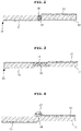
- FIGs. 5A and 5B are respectively a plan view and a sectional view of a pressure sensor according to a second embodiment of the present invention
- FIG. 6 is a sectional view of a modification of the pressure sensor according to the second embodiment of the present invention
- FIG. 7 is a sectional view of another modification of the pressure sensor according to the second embodiment of the present invention
- FIG. 8 is a sectional view of an example in which a bump is coupled to the pressure sensor according to the second embodiment of the present invention.
- the pressure sensor according to the second embodiment of the present invention includes a base material 10, a first through-hole 11a and a second through-hole 11b formed on one surface of the base material 11, the first through-hole and the second through-hole being formed through the base material 10 so as to extend from the upper surface to the lower surface thereof, and a conductive thread sensor 20, the conductive thread sensor including a first signal line 21 extending from one side of the base material 10, a sensing portion 22 extending from the first signal line 21 so as to continuously extend from one surface of the base material 10 via the first through-hole 11a and the second through-hole 11b, the sensing portion being coupled to the first through-hole and the second through-hole, and a second signal line 23 extending from the sensing portion 22 so as to extend to the other side of the base material 10.
- the pressure sensor according to the second embodiment of the present invention has a structure in which the two through-holes 11, i.e. the first through-hole 11a and the second through-hole 11b, are formed in the base material 10 and the conductive thread sensor 20 is coupled to the first through-hole and the second through-hole.
- the second embodiment of the present invention is different from the first embodiment of the present invention in that the conductive thread sensor is coupled to the first through-hole 11a and the second through-hole 11b and that the conductive thread sensor is wound a plurality of times around the base material 10 between the first through-hole 11a and the second through-hole 11b, whereby deformation of the base material 10 by pressure in a vertical direction may be increased, and therefore it is possible to further improve pressure sensing sensitivity.
- the interiors of the first through-hole 11a and the second through-hole 11b are filled with conductive paste 30, which is coupled to the sensing portion 22 of the conductive thread sensor 20, which is identical in structure to the first embodiment of the present invention, and therefore a detailed description thereof will be omitted.
- the sensing portion 22 may be alternately wound a plurality of times through the first through-hole 11a and the second through-hole 11b.
- the conductive thread parts of the sensing portion 22 wound a plurality of times may be wound in the same plane in a state of being spaced apart from each other so as to be insulated from each other, and may be wound a plurality of times in a coil shape.
- a first bump 50a and a second bump 50b are formed so as to cover the first through-hole 11a and the second through-hole 11b, respectively, whereby it is possible to concentrate pressure of the base material 10 on the sensing portion 22, and therefore it is possible to improve accuracy and reliability in pressure sensing through this structural design, in the same manner as in the first embodiment.
- the sensing portion may be made of an insulating material or may be formed so as to have higher resistance than the first and second signal lines 21 and 23, whereby it is possible to improve sensing sensitivity of the sensing portion 22 (22a), in the same manner as in FIG. 1C . A duplicate description thereof will be omitted.
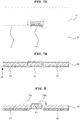
- FIG. 9 is a plan view of a pressure sensor according to a third embodiment of the present invention
- FIG. 10 is a plan view of a modification of the pressure sensor according to the third embodiment of the present invention.
- a plurality of through-holes 11 is formed in a base material 10, and conductive thread parts of a sensing portion of a conductive thread sensor 20 are wound once or a plurality of times so as to be connected to each other while extending through the through-holes 11, whereby it is possible to secure sensing sensitivity and a sensing region of the conductive thread sensor.
- the third embodiment of the present invention is identical in construction to the first embodiment and the second embodiment of the present invention, and therefore a detailed description thereof will be omitted.
- the sensing portion 22 (22a) may be made of an insulating material or may be formed so as to have higher resistance than the first and second signal lines 21 and 23, whereby it is possible to improve sensing sensitivity of the sensing portion 22 (22a), in the same manner as in FIG. 1C .
- FIGs. 11A and 11B are respectively a plan view and a sectional view of a pressure sensor according to a fourth embodiment of the present invention.
- the pressure sensor according to the fourth embodiment of the present invention shown in FIGs. 11A and 11B includes a base material 10, a through-hole 11 formed on one surface of the base material, the through-hole being formed through the base material 10 so as to extend from the upper surface to the lower surface thereof, a first signal line 21 extending from one side of the base material 10, a first electrode portion 21a extending from the first signal line 21 so as to extend through the through-hole 11 from one surface of the base material 10 and to be coupled to one side of the inner circumferential surface of the through-hole, a second signal line 23 extending from the other side of the base material 10, a second electrode portion 23a extending from the second signal line 23 so as to extend through the through-hole 11 from one surface of the base material 10 and to be coupled to the other side of the inner circumferential surface of the through-hole, the second electrode portion being spaced apart from the first electrode portion 21a while facing the first electrode portion, and a dielectric substance, with which a space between the first electrode portion 21a and the second electrode portion
- the first electrode portion 21a is formed so as to be coupled to one side of the inner circumferential surface of the through-hole 11 of the base material 10
- the first signal line 21 is formed so as to extend from the first electrode portion 21a for electrical connection
- the second electrode portion 23a is formed so as to be coupled to the other side of the inner circumferential surface of the through-hole 11, the second electrode portion being disposed so as to face the first electrode portion 21a
- the second signal line 23 is formed so as to extend to the other side of the base material 10 for electrical connection of the second electrode portion 23a.
- the space between the first electrode portion 21a and the second electrode portion 23a is filled with a dielectric substance, whereby it is possible to sense a change in external pressure and a pressure value thereof through a change in capacitance depending on a change in distance between the first electrode portion 21a and the second electrode portion 23a.
- FIG. 12 schematically shows that the sensing portion 22 of the conductive thread sensor 20 is deformed together with the base material 10 when pressure is applied to the pressure sensor according to the present invention from above.
- a pressure sensor using conductive thread is capable of measuring electrical resistance and capacitance depending on the structure thereof and the kind of a filling material, and it is possible to maximize a change of the resistance value and the capacitance value through contraction and relaxation of the sensing portion 22 coupled so as to extend through the through-hole 11 in the vertical direction depending on deformation of the base material by external pressure, whereby it is possible to improve reliability of the measured values.
Landscapes
- Physics & Mathematics (AREA)
- General Physics & Mathematics (AREA)
- Measuring Fluid Pressure (AREA)
Abstract
Description
- An embodiment of the present invention relates to a pressure sensor.
- Conventional pressure sensors are coupled a general substrate or base material as a thin film in a plane so as to respond to contraction and relaxation of the base material depending on deformation thereof in order to sense the degree of bending or deformation of the base material.
- However, with a recent increase in forming sensors using various base materials, such as a general flexible substrate, a fiber material, and structures having great degree of deformation, research on a pressure sensor capable of effectively responding to deformation of the base material itself and having high application flexibility has inevitably emerged.
- (Patent Document 1)
KR 101301277 B1 - It is an object of an embodiment of the present invention to provide a pressure sensor freely applied to various flexible materials to effectively sense a change in external pressure.
- It is another object of the present invention to perform pressure sensing based on various materials and shapes through structural application of conductive thread to the pressure sensor and structural change for effectively improving pressure sensing sensitivity of the conductive thread.
- It is a further object of the present invention to effectively sense a change in capacitance as well as a change in resistance depending on external pressure while maintaining sensitivity, whereby the pressure sensor is effectively applicable to various emerging fields, such as wearable materials.
- A pressure sensor according to a first embodiment of the present invention includes a base material, a through-hole formed through the base material so as to extend from an upper surface to a lower surface thereof, and a conductive thread sensor including conductive thread extending through the through-hole.
- Here, the conductive thread sensor may include a first signal line extending from one side of the base material, a sensing portion extending from the first signal line so as to extend from one surface of the base material to the other surface of the base material via an inside of the through-hole, and a second signal line extending from the sensing portion so as to extend to the other side of the base material.
- In addition, the sensing portion may be formed in an inner space of the through-hole so as to be bent upwards and downwards a plurality of times, and the inner space of the through-hole and a space between the bent parts of the sensing portion bent the plurality of times may be filled with an insulating material configured to elastically support an upper part and a lower part of the through-hole.
- In addition, an interior of the through-hole may be filled with conductive paste, the conductive paste being coupled to the sensing portion and elastically supported in an upward-downward direction of the base material.
- In addition, the pressure sensor may further include a bump coupled to the one surface of the base material so as to cover the through-hole, the bump being convex upwards.
- In addition, the sensing portion may be formed so as to have higher resistance than the first signal line and the second signal line.
- In addition, the sensing portion may be made of an insulating material.
- A pressure sensor according to a second embodiment of the present invention includes a base material, a first through-hole and a second through-hole formed on one surface of the base material, the first through-hole and the second through-hole being formed through the base material so as to extend from an upper surface to a lower surface thereof, and a conductive thread sensor, the conductive thread sensor including a first signal line extending from one side of the base material, a sensing portion extending from the first signal line so as to continuously extend from the one surface of the base material via the first through-hole and the second through-hole, the sensing portion being coupled to the first through-hole and the second through-hole, and a second signal line extending from the sensing portion so as to extend to the other side of the base material.
- Here, the sensing portion may extend through the first through-hole and the second through-hole and may be formed so as to be wound a plurality of times between the first through-hole and the second through-hole.
- In addition, an interior of each of the first through-hole and the second through-hole may be filled with conductive paste, the conductive paste being coupled to the sensing portion and configured to elastically support an upper part and a lower part of the sensing portion.
- In addition, the pressure sensor may further include a first bump coupled to the one surface of the base material so as to cover the first through-hole, the first bump being formed so as to be convex upwards, and a second bump coupled to the one surface of the base material so as to cover the second through-hole, the second bump being formed so as to be convex upwards.
- In addition, the sensing portion may be formed so as to have higher resistance than the first signal line and the second signal line.
- In addition, the sensing portion may be made of an insulating material.
- A pressure sensor according to a third embodiment of the present invention includes a base material, a plurality of through-holes formed on one surface of the base material, the plurality of through-holes being formed through the base material so as to extend from an upper surface to a lower surface thereof, and a conductive thread sensor, the conductive thread sensor including a first signal line extending from one side of the base material, a sensing portion extending from the first signal line so as to continuously extend from the one surface of the base material via the plurality of through-holes, the sensing portion being coupled to the plurality of through-holes, and a second signal line extending from the sensing portion so as to extend to the other side of the base material.
- Here, the sensing portion may continuously extend through the plurality of through-holes, may be coupled to the plurality of through-holes, and may be coupled so as to be wound a plurality of times between adjacent ones of the through-holes.
- In addition, an interior of each of the plurality of through-holes may be filled with conductive paste, the conductive paste being coupled to the sensing portion and elastically supported in an upward-downward direction of the base material.
- In addition, the pressure sensor may further include a plurality of bumps coupled to the one surface of the base material so as to cover the plurality of through-holes, each of the plurality of bumps being formed so as to be convex upwards.
- In addition, the sensing portion may be formed so as to have higher resistance than the first signal line and the second signal line.
- In addition, the sensing portion may be made of an insulating material.
- A pressure sensor according to a fourth embodiment of the present invention includes a base material, a through-hole formed on one surface of the base material, the through-hole being formed through the base material so as to extend from an upper surface to a lower surface thereof, a first signal line extending from one side of the base material, a first electrode portion extending from the first signal line so as to extend through the through-hole from the one surface of the base material and to be coupled to one side of an inner circumferential surface of the through-hole, a second signal line extending from the other side of the base material, a second electrode portion extending from the second signal line so as to extend through the through-hole from the one surface of the base material and to be coupled to the other side of the inner circumferential surface of the through-hole, the second electrode portion being spaced apart from the first electrode portion while facing the first electrode portion, and a dielectric substance, with which a space between the first electrode portion and the second electrode portion is filled.
- The features and advantages of the present invention will be more clearly understood from the following detailed description taken in conjunction with the accompanying drawings.
- It should be understood that the terms used in the specification and appended claims should not be construed as being limited to general and dictionary meanings, but should be construed based on meanings and concepts according to the spirit of the present invention on the basis of the principle that the inventor is permitted to define appropriate terms for the best explanation.
- According to an embodiment of the present invention, a pressure sensor is implemented through structural coupling between conductive thread and a base material, whereby it is possible to achieve application to a variety of recent wearable flexible materials, to effectively respond to deformation of a base material itself, and to effectively increase the degree of design freedom.
- In addition, it is possible to stably respond to structural deformation in application to various flexible materials and to effectively improve sensitivity in pressure sensing through a coupling structure with the flexible material.
- In addition, it is possible to implement a pressure sensor capable of measuring a change in capacitance as well as a change in resistance for pressure sensing, whereby it is possible to improve reliability in pressure sensing in various environments appropriate for use.
- In addition, it is possible to effectively sense pressure distribution depending on a change in various shapes or a change in movement based on application fields, in addition to simple pressure sensing, whereby it is possible to effectively monitor the behavior of people during working in various environments.
- In addition, it is possible to implement a point structure for partial pressure sensing as a bump, in addition to implementation of the pressure sensor through conductive thread, whereby it is possible to transfer overall pressure to an effective sensing point, and therefore it is possible to more effectively improve accuracy and reliability in pressure sensing.
-
-
FIGs. 1A, 1B, and 1C are respectively a plan view, a sectional view, and another sectional view of a pressure sensor according to a first embodiment of the present invention. -
FIG. 2 is a sectional view of a modification of the pressure sensor according to the first embodiment of the present invention. -
FIG. 3 is a sectional view of another modification of the pressure sensor according to the first embodiment of the present invention. -
FIG. 4 is a sectional view of an example in which a bump is coupled to the pressure sensor according to the first embodiment of the present invention. -
FIGs. 5A and 5B are respectively a plan view and a sectional view of a pressure sensor according to a second embodiment of the present invention. -
FIG. 6 is a sectional view of a modification of the pressure sensor according to the second embodiment of the present invention. -
FIG. 7 is a sectional view of another modification of the pressure sensor according to the second embodiment of the present invention. -
FIG. 8 is a sectional view of an example in which a bump is coupled to the pressure sensor according to the second embodiment of the present invention. -
FIG. 9 is a plan view of a pressure sensor according to a third embodiment of the present invention. -
FIG. 10 is a plan view of a modification of the pressure sensor according to the third embodiment of the present invention. -
FIGs. 11A and 11B are respectively a plan view and a sectional view of a pressure sensor according to a fourth embodiment of the present invention. -
FIG. 12 is a schematic view showing the operation of the pressure sensor according to the second embodiment of the present invention. - Objects, specific advantages, and novel features of an embodiment of the present invention will be apparent from exemplary embodiments and the following detailed description in connection with the accompanying drawings. It should be noted that when reference numerals are assigned to the elements of the drawings, the same reference numeral is assigned to the same elements even when they are illustrated in different drawings. Furthermore, the terms "one surface", "the other surface", "first", "second", etc. are only used to distinguish one element from another element, and these elements are not to be construed as being limited by these terms. In the following description of an embodiment of the present invention, a detailed description of known technology incorporated herein will be omitted when it may obscure the subject matter of an embodiment of the present invention.
- Hereinafter, an embodiment of the present invention will be described in detail with reference to the accompanying drawings, and the same reference numerals indicate the same members.
-
FIGs. 1A, 1B, and 1C are respectively a plan view, a sectional view, and another sectional view of a pressure sensor according to a first embodiment of the present invention,FIG. 2 is a sectional view of a modification of the pressure sensor according to the first embodiment of the present invention,FIG. 3 is a sectional view of another modification of the pressure sensor according to the first embodiment of the present invention, andFIG. 4 is a sectional view of an example in which abump 50 is coupled to the pressure sensor according to the first embodiment of the present invention. - The pressure sensor according to the first embodiment of the present invention includes a
base material 10, a through-hole 11 formed through thebase material 10 so as to extend from the upper surface to the lower surface thereof, and aconductive thread sensor 20, the conductive thread sensor including afirst signal line 21 extending from one side of thebase material 10, asensing portion 22 extending from thefirst signal line 21 so as to extend from one surface of thebase material 10 to the other surface of thebase material 10 via the inside of the through-hole 11, and asecond signal line 23 extending from thesensing portion 22 so as to extend to the other side of thebase material 10. - As shown in
FIG. 1A , the through-hole 11 is formed in thebase material 10, and thesensing portion 22 is coupled to the through-hole 11 in an upward-downward direction, i.e. through thebase material 10 from the upper surface to the lower surface thereof in a thickness direction thereof. - The
base material 10 means a general flexible material, and may be a fiber material or a flexible material having any of various shapes. With universalization of wearable devices, pressure sensing based on the form of clothes, which people wear, or various other forms is necessary, and therefore technology for applying pressure sensors capable of effectively corresponding to deformation of thebase material 10, which is flexible, is required. - The pressure sensor according to the embodiment of the present invention may be implemented as a pressure sensor using conductive thread. The conductive thread may be made of a conductive composite fiber material, or flexible line type conductive thread may be manufactured through printing of conductive ink or conductive coating. The conductive thread has a structural advantage in that the degree of freedom in flexible structural deformation of the conductive thread is high, whereby it is possible to effectively sense pressure in response to flexible structural deformation of the
base material 10 without being broken thereby. - The
conductive thread sensor 20 is formed so as to include thefirst signal line 21, which extends from one side of thebase material 10 so as to serve to perform electrical connection, the sensingportion 22, which is coupled to the through-hole 11 of thebase material 10 so as to sense pressure based on a change in resistance through deformation corresponding to actual pressure, and thesecond signal line 23 extending from the sensingportion 22 to the other side of thebase material 10 so as to perform electrical connection. - The reason that the through-
hole 11 is formed and the conductive thread is coupled in a direction in which the conductive thread extends through the through-hole 11 is that vertical deformation, not horizontal deformation, of the conductive thread is induced in response to pressure, whereby it is possible to improve sensing sensitivity. - Here, as shown in
FIG. 1C , only the conductive thread part of the sensing portion 22 (22a) extending through the through-hole 11 may be made of conductive thread having higher resistance than the other part, or only thesensing portion 22 may be made of an insulating material. For example, the sensing portion 22 (22a) of theconductive thread sensor 20 may be coated with insulation, or in the case in which a material from which conductive thread is manufactured is an insulating material, only the first andsecond signal lines conductive thread sensor 20. - In addition, as shown in
FIG. 2 , the interior of the through-hole 11 may be filled with a material that is effectively elastically supported with respect to external pressure, such asconductive paste 30, in addition to thesensing portion 22 made of conductive thread, whereby a change in resistance may be increased, and therefore, it is possible to improve sensitivity in pressure sensing. - In
FIG. 3 , the sensingportion 22 of theconductive thread sensor 20 may be inserted into the through-hole 11 of thebase material 10 in a curved state so as to be bent upwards and downwards a plurality of times, whereby it is possible to further improve sensitivity in pressure sensing. The interior of the through-hole may be filled with an insulating material configured to maintain electrical insulation between the bent parts of thesensing portion 22, such as adielectric substance 40. It is appropriate to select a material capable of elastically responding to external pressure as the insulating material and to adjust the filling rate of the insulating material. -
FIG. 4 shows that thebump 50 is coupled to the upper surface of the throughhole 11 of thebase material 10 so as to be convex upwards in order to cover the upper surface of the through hole. In the case in which thebump 50 is coupled to the upper surface of the through hole so as to be convex upwards, pressure applied to the upper surface of the through hole may be effectively transferred to thesensing portion 22 through thebump 50, whereby it is possible to secure accuracy in pressure sensing. Thebump 50 may be made of an insulating material. For example, various materials, such as epoxy, may be used. However, it is appropriate to manufacture the bump so as to have elastic force or supporting force necessary to effectively transfer pressure and to couple the bump to thebase material 10. -
FIGs. 5A and 5B are respectively a plan view and a sectional view of a pressure sensor according to a second embodiment of the present invention,FIG. 6 is a sectional view of a modification of the pressure sensor according to the second embodiment of the present invention,FIG. 7 is a sectional view of another modification of the pressure sensor according to the second embodiment of the present invention, andFIG. 8 is a sectional view of an example in which a bump is coupled to the pressure sensor according to the second embodiment of the present invention. - The pressure sensor according to the second embodiment of the present invention includes a
base material 10, a first through-hole 11a and a second through-hole 11b formed on one surface of thebase material 11, the first through-hole and the second through-hole being formed through thebase material 10 so as to extend from the upper surface to the lower surface thereof, and aconductive thread sensor 20, the conductive thread sensor including afirst signal line 21 extending from one side of thebase material 10, asensing portion 22 extending from thefirst signal line 21 so as to continuously extend from one surface of thebase material 10 via the first through-hole 11a and the second through-hole 11b, the sensing portion being coupled to the first through-hole and the second through-hole, and asecond signal line 23 extending from the sensingportion 22 so as to extend to the other side of thebase material 10. - As shown in
FIG. 5 , the pressure sensor according to the second embodiment of the present invention has a structure in which the two through-holes 11, i.e. the first through-hole 11a and the second through-hole 11b, are formed in thebase material 10 and theconductive thread sensor 20 is coupled to the first through-hole and the second through-hole. - The second embodiment of the present invention is different from the first embodiment of the present invention in that the conductive thread sensor is coupled to the first through-
hole 11a and the second through-hole 11b and that the conductive thread sensor is wound a plurality of times around thebase material 10 between the first through-hole 11a and the second through-hole 11b, whereby deformation of thebase material 10 by pressure in a vertical direction may be increased, and therefore it is possible to further improve pressure sensing sensitivity. - As shown in
FIG. 6 , the interiors of the first through-hole 11a and the second through-hole 11b are filled withconductive paste 30, which is coupled to thesensing portion 22 of theconductive thread sensor 20, which is identical in structure to the first embodiment of the present invention, and therefore a detailed description thereof will be omitted. - As shown in
FIGs. 7A and 7B , the sensingportion 22 may be alternately wound a plurality of times through the first through-hole 11a and the second through-hole 11b. In this case, the conductive thread parts of thesensing portion 22 wound a plurality of times may be wound in the same plane in a state of being spaced apart from each other so as to be insulated from each other, and may be wound a plurality of times in a coil shape. - In
FIG. 8 , afirst bump 50a and asecond bump 50b are formed so as to cover the first through-hole 11a and the second through-hole 11b, respectively, whereby it is possible to concentrate pressure of thebase material 10 on thesensing portion 22, and therefore it is possible to improve accuracy and reliability in pressure sensing through this structural design, in the same manner as in the first embodiment. - Even in this embodiment, the sensing portion may be made of an insulating material or may be formed so as to have higher resistance than the first and
second signal lines FIG. 1C . A duplicate description thereof will be omitted. -
FIG. 9 is a plan view of a pressure sensor according to a third embodiment of the present invention, andFIG. 10 is a plan view of a modification of the pressure sensor according to the third embodiment of the present invention. - As shown in
FIGs. 9 and10 , in the third embodiment of the present invention, a plurality of through-holes 11 is formed in abase material 10, and conductive thread parts of a sensing portion of aconductive thread sensor 20 are wound once or a plurality of times so as to be connected to each other while extending through the through-holes 11, whereby it is possible to secure sensing sensitivity and a sensing region of the conductive thread sensor. The third embodiment of the present invention is identical in construction to the first embodiment and the second embodiment of the present invention, and therefore a detailed description thereof will be omitted. - Even in this embodiment, the sensing portion 22 (22a) may be made of an insulating material or may be formed so as to have higher resistance than the first and
second signal lines FIG. 1C . -
FIGs. 11A and 11B are respectively a plan view and a sectional view of a pressure sensor according to a fourth embodiment of the present invention. - The pressure sensor according to the fourth embodiment of the present invention shown in
FIGs. 11A and 11B includes abase material 10, a through-hole 11 formed on one surface of the base material, the through-hole being formed through thebase material 10 so as to extend from the upper surface to the lower surface thereof, afirst signal line 21 extending from one side of thebase material 10, afirst electrode portion 21a extending from thefirst signal line 21 so as to extend through the through-hole 11 from one surface of thebase material 10 and to be coupled to one side of the inner circumferential surface of the through-hole, asecond signal line 23 extending from the other side of thebase material 10, a second electrode portion 23a extending from thesecond signal line 23 so as to extend through the through-hole 11 from one surface of thebase material 10 and to be coupled to the other side of the inner circumferential surface of the through-hole, the second electrode portion being spaced apart from thefirst electrode portion 21a while facing the first electrode portion, and a dielectric substance, with which a space between thefirst electrode portion 21a and the second electrode portion 23a is filled. - As shown in
FIGs. 11A and 11B , in the fourth embodiment of the present invention, there is shown that pressure is sensed through a change in capacitance depending on deformation by pressure. That is, thefirst electrode portion 21a is formed so as to be coupled to one side of the inner circumferential surface of the through-hole 11 of thebase material 10, thefirst signal line 21 is formed so as to extend from thefirst electrode portion 21a for electrical connection, the second electrode portion 23a is formed so as to be coupled to the other side of the inner circumferential surface of the through-hole 11, the second electrode portion being disposed so as to face thefirst electrode portion 21a, and thesecond signal line 23 is formed so as to extend to the other side of thebase material 10 for electrical connection of the second electrode portion 23a. - The space between the
first electrode portion 21a and the second electrode portion 23a is filled with a dielectric substance, whereby it is possible to sense a change in external pressure and a pressure value thereof through a change in capacitance depending on a change in distance between thefirst electrode portion 21a and the second electrode portion 23a. - Only one example is shown, and therefore it is possible to implement various capacitance measurement structures based on the above-described capacitance measurement structure.
- Also, in the case in which a plurality of through-
holes 11 is formed, as in the third embodiment of the present invention, it is possible to simultaneously sense a change in capacitance as well as a change in resistance value depending on pressure through the plurality of through-holes 11, whereby it is possible to improve overall sensing sensitivity and reliability of the pressure sensor and to perform effective design change based on various environments and uses to which the present invention is applied. - Finally,
FIG. 12 schematically shows that thesensing portion 22 of theconductive thread sensor 20 is deformed together with thebase material 10 when pressure is applied to the pressure sensor according to the present invention from above. Such a pressure sensor using conductive thread is capable of measuring electrical resistance and capacitance depending on the structure thereof and the kind of a filling material, and it is possible to maximize a change of the resistance value and the capacitance value through contraction and relaxation of thesensing portion 22 coupled so as to extend through the through-hole 11 in the vertical direction depending on deformation of the base material by external pressure, whereby it is possible to improve reliability of the measured values. - Although the present invention has been described in detail with reference to specific embodiments, those embodiments are provided only for illustrative purposes. Therefore, the pressure sensor according to the present invention is not limited to those embodiments, but rather those skilled in the art will appreciate that various modifications, additions and substitutions are possible, without departing from the scope and spirit of the invention as disclosed in the accompanying claims. Simple changes and modifications of the present invention are to be appreciated as being included in the scope and spirit of the invention, and the protection scope of the present invention will be defined by the accompanying claims.
Claims (20)
- A pressure sensor comprising:a base material;a through-hole formed through the base material so as to extend from an upper surface to a lower surface thereof; anda conductive thread sensor comprising conductive thread extending through the through-hole.
- The pressure sensor according to claim 1, wherein the conductive thread sensor comprises:a first signal line extending from one side of the base material;a sensing portion extending from the first signal line so as to extend from one surface of the base material to the other surface of the base material via an inside of the through-hole; anda second signal line extending from the sensing portion so as to extend to the other side of the base material.
- The pressure sensor according to claim 1, whereinthe sensing portion is formed in an inner space of the through-hole so as to be bent upwards and downwards a plurality of times, andthe inner space of the through-hole and a space between the bent parts of the sensing portion bent the plurality of times are filled with an insulating material configured to elastically support an upper part and a lower part of the through-hole.
- The pressure sensor according to claim 1, wherein an interior of the through-hole is filled with conductive paste, the conductive paste being coupled to the sensing portion and elastically supported in an upward-downward direction of the base material.
- The pressure sensor according to claim 1, further comprising a bump coupled to the one surface of the base material so as to cover the through-hole, the bump being convex upwards.
- The pressure sensor according to claim 2, wherein the sensing portion is formed so as to have higher resistance than the first signal line and the second signal line.
- The pressure sensor according to claim 2, wherein the sensing portion is made of an insulating material.
- A pressure sensor comprising:a base material;a first through-hole and a second through-hole formed on one surface of the base material, the first through-hole and the second through-hole being formed through the base material so as to extend from an upper surface to a lower surface thereof; anda conductive thread sensor, the conductive thread sensor comprising a first signal line extending from one side of the base material, a sensing portion extending from the first signal line so as to continuously extend from the one surface of the base material via the first through-hole and the second through-hole, the sensing portion being coupled to the first through-hole and the second through-hole, and a second signal line extending from the sensing portion so as to extend to the other side of the base material.
- The pressure sensor according to claim 8, wherein the sensing portion extends through the first through-hole and the second through-hole and is formed so as to be wound a plurality of times between the first through-hole and the second through-hole.
- The pressure sensor according to claim 8, wherein an interior of each of the first through-hole and the second through-hole is filled with conductive paste, the conductive paste being coupled to the sensing portion and configured to elastically support an upper part and a lower part of the sensing portion.
- The pressure sensor according to claim 8, further comprising:a first bump coupled to the one surface of the base material so as to cover the first through-hole, the first bump being formed so as to be convex upwards; anda second bump coupled to the one surface of the base material so as to cover the second through-hole, the second bump being formed so as to be convex upwards.
- The pressure sensor according to claim 8, wherein the sensing portion is formed so as to have higher resistance than the first signal line and the second signal line.
- The pressure sensor according to claim 8, wherein the sensing portion is made of an insulating material.
- A pressure sensor comprising:a base material;a plurality of through-holes formed on one surface of the base material, the plurality of through-holes being formed through the base material so as to extend from an upper surface to a lower surface thereof; anda conductive thread sensor, the conductive thread sensor comprising a first signal line extending from one side of the base material, a sensing portion extending from the first signal line so as to continuously extend from the one surface of the base material via the plurality of through-holes, the sensing portion being coupled to the plurality of through-holes, and a second signal line extending from the sensing portion so as to extend to the other side of the base material.
- The pressure sensor according to claim 14, wherein the sensing portion continuously extends through the plurality of through-holes, is coupled to the plurality of through-holes, and is coupled so as to be wound a plurality of times between adjacent ones of the through-holes.
- The pressure sensor according to claim 14, wherein an interior of each of the plurality of through-holes is filled with conductive paste, the conductive paste being coupled to the sensing portion and elastically supported in an upward-downward direction of the base material.
- The pressure sensor according to claim 14, further comprising a plurality of bumps coupled to the one surface of the base material so as to cover the plurality of through-holes, each of the plurality of bumps being formed so as to be convex upwards.
- The pressure sensor according to claim 14, wherein the sensing portion is formed so as to have higher resistance than the first signal line and the second signal line.
- The pressure sensor according to claim 14, wherein the sensing portion is made of an insulating material.
- A pressure sensor comprising:a base material;a through-hole formed on one surface of the base material, the through-hole being formed through the base material so as to extend from an upper surface to a lower surface thereof;a first signal line extending from one side of the base material and a first electrode portion extending from the first signal line so as to extend through the through-hole from the one surface of the base material and to be coupled to one side of an inner circumferential surface of the through-hole;a second signal line extending from the other side of the base material and a second electrode portion extending from the second signal line so as to extend through the through-hole from the one surface of the base material and to be coupled to the other side of the inner circumferential surface of the through-hole, the second electrode portion being spaced apart from the first electrode portion while facing the first electrode portion; anda dielectric substance, with which a space between the first electrode portion and the second electrode portion is filled.
Applications Claiming Priority (2)
| Application Number | Priority Date | Filing Date | Title |
|---|---|---|---|
| KR1020190109152A KR102318554B1 (en) | 2019-09-03 | 2019-09-03 | Pressure Sensor |
| PCT/KR2020/008574 WO2021045365A1 (en) | 2019-09-03 | 2020-07-01 | Pressure sensor |
Publications (4)
| Publication Number | Publication Date |
|---|---|
| EP4027125A1 true EP4027125A1 (en) | 2022-07-13 |
| EP4027125A4 EP4027125A4 (en) | 2023-10-11 |
| EP4027125B1 EP4027125B1 (en) | 2026-03-04 |
| EP4027125C0 EP4027125C0 (en) | 2026-03-04 |
Family
ID=74852497
Family Applications (1)
| Application Number | Title | Priority Date | Filing Date |
|---|---|---|---|
| EP20861328.1A Active EP4027125B1 (en) | 2019-09-03 | 2020-07-01 | Pressure sensor |
Country Status (4)
| Country | Link |
|---|---|
| US (1) | US12152948B2 (en) |
| EP (1) | EP4027125B1 (en) |
| KR (1) | KR102318554B1 (en) |
| WO (1) | WO2021045365A1 (en) |
Families Citing this family (3)
| Publication number | Priority date | Publication date | Assignee | Title |
|---|---|---|---|---|
| TWI781403B (en) * | 2020-05-14 | 2022-10-21 | 美宸科技股份有限公司 | Fabric strain gauge, fabric pressure gauge, and smart clothing |
| KR102610658B1 (en) * | 2022-02-17 | 2023-12-06 | 한국생산기술연구원 | Conductive substrate having conductive structure using liquid metal and functional clothing including the same |
| CN117232673A (en) * | 2023-09-20 | 2023-12-15 | 钛深科技(深圳)有限公司 | Temperature sensing film and manufacturing method thereof, and manufacturing method of temperature and pressure sensing film |
Family Cites Families (33)
| Publication number | Priority date | Publication date | Assignee | Title |
|---|---|---|---|---|
| JPH10132677A (en) * | 1996-10-31 | 1998-05-22 | Matsushita Electric Works Ltd | Pressure sensor |
| AU2003279888A1 (en) * | 2002-06-28 | 2004-01-19 | North Carolina State University | Fabric and yarn structures for improving signal integrity in fabric based electrical circuits |
| US9695530B2 (en) * | 2011-08-11 | 2017-07-04 | Deborah Jean Hall | Apparatus to facilitate the commencement and execution of off-loom bead weaving stitches and method(s) of using same |
| WO2016109744A1 (en) * | 2014-12-31 | 2016-07-07 | Sensoria Inc. | Sensors, interfaces and sensor systems for data collection and integrated monitoring of conditions at or near body surfaces |
| DE102012103856B4 (en) * | 2012-02-16 | 2016-09-29 | Peter Seitz | Textile pressure sensor |
| WO2013181474A1 (en) * | 2012-05-30 | 2013-12-05 | Medisens Wireless, Inc. | Pressure signature based biometric systems, sensor assemblies and methods |
| KR101301277B1 (en) | 2012-07-30 | 2013-08-27 | 주식회사 마블덱스 | Input device with membrane pressure sensor and proximity sensor. |
| US9322121B2 (en) * | 2013-02-28 | 2016-04-26 | Regents Of The University Of Minnesota | Stitched stretch sensor |
| WO2015014950A1 (en) * | 2013-07-31 | 2015-02-05 | Universita' Degli Studi Di Cagliari | Textile pressure sensor and method for fabricating the same |
| US20160194792A1 (en) * | 2014-07-09 | 2016-07-07 | Mas Innovation (Private) Limited | Electrically conductive textile assemblies and manufacture thereof |
| JP6623218B2 (en) * | 2014-09-30 | 2019-12-18 | アップル インコーポレイテッドApple Inc. | Fabric sensing device |
| KR101716695B1 (en) * | 2014-12-31 | 2017-03-15 | 한국패션산업연구원 | Three-dimensional structure fabric sensor capable of bio signal measurement and pressure measurement |
| US20180330886A1 (en) * | 2015-01-15 | 2018-11-15 | Stretchsense Limited | Electromechanical device with improved connection |
| CN108235793B (en) * | 2015-01-27 | 2020-01-07 | 荷兰应用自然科学研究组织Tno | Flexible device module and production method for fabric layer assembly |
| WO2017065270A1 (en) * | 2015-10-16 | 2017-04-20 | 国立研究開発法人科学技術振興機構 | Stress-alleviating substrate and textile device |
| KR102382320B1 (en) * | 2015-12-11 | 2022-04-04 | 엘지이노텍 주식회사 | Pressure sensor device |
| US9816799B2 (en) * | 2015-12-18 | 2017-11-14 | Oculus Vr, Llc | Embroidered strain sensing elements |
| US20170347721A1 (en) * | 2016-06-01 | 2017-12-07 | University Of Delaware | Conductive thread stitched stretch sensor |
| US10925540B2 (en) * | 2016-08-18 | 2021-02-23 | MAD Apparel, Inc. | Garment with conductive thread exposed on both sides |
| AT518546B1 (en) * | 2016-09-27 | 2017-11-15 | Stapptronics Gmbh | Insole or shoe sole |
| JP6799817B2 (en) * | 2016-11-28 | 2020-12-16 | パナソニックIpマネジメント株式会社 | Flexible wiring boards, electronic devices, textile products |
| DE102016123646A1 (en) * | 2016-12-07 | 2018-06-07 | Brose Fahrzeugteile Gmbh & Co. Kommanditgesellschaft, Bamberg | Measuring electrode for a capacitive proximity sensor of a motor vehicle |
| JP6829365B2 (en) * | 2017-01-12 | 2021-02-10 | 国立研究開発法人産業技術総合研究所 | Pressure sensors, pressure sensor manufacturing methods, bed devices and automotive seats |
| DE102017100786B4 (en) * | 2017-01-17 | 2018-09-06 | Pilz Gmbh & Co. Kg | Tactile sensor with housing |
| US20190072440A1 (en) * | 2017-08-31 | 2019-03-07 | Simon Fraser University | Fibre-based sensor for yarn |
| KR102420891B1 (en) * | 2017-11-20 | 2022-07-15 | 한국생산기술연구원 | Fabric Pressure Sensor |
| KR102052461B1 (en) * | 2017-11-24 | 2019-12-06 | 한국기계연구원 | 3d air-mesh textile with resistive sensing information |
| EP3937845A4 (en) * | 2019-03-13 | 2022-06-22 | Atex Technologies, Inc. | INDICATOR MARKING TECHNOLOGY FOR TEXTILES |
| EP3736528B1 (en) * | 2019-05-09 | 2023-05-17 | Nokia Technologies Oy | A strain sensor and methods and apparatuses for using a strain sensor |
| DE102019120191B3 (en) * | 2019-07-25 | 2020-12-24 | Deutsche Institute Für Textil- Und Faserforschung Denkendorf | Embroidered sensor |
| JP7297611B2 (en) * | 2019-09-10 | 2023-06-26 | 日本航空電子工業株式会社 | electrical relay material |
| JP7493167B2 (en) * | 2020-01-27 | 2024-05-31 | パナソニックIpマネジメント株式会社 | Load Sensor |
| US11841281B2 (en) * | 2021-06-03 | 2023-12-12 | Accenture Global Solutions Limited | Flexible pressure sensors |
-
2019
- 2019-09-03 KR KR1020190109152A patent/KR102318554B1/en active Active
-
2020
- 2020-07-01 EP EP20861328.1A patent/EP4027125B1/en active Active
- 2020-07-01 WO PCT/KR2020/008574 patent/WO2021045365A1/en not_active Ceased
-
2022
- 2022-03-01 US US17/684,156 patent/US12152948B2/en active Active
Also Published As
| Publication number | Publication date |
|---|---|
| US12152948B2 (en) | 2024-11-26 |
| WO2021045365A1 (en) | 2021-03-11 |
| KR102318554B1 (en) | 2021-10-29 |
| EP4027125B1 (en) | 2026-03-04 |
| EP4027125C0 (en) | 2026-03-04 |
| US20220187144A1 (en) | 2022-06-16 |
| KR20210027989A (en) | 2021-03-11 |
| EP4027125A4 (en) | 2023-10-11 |
Similar Documents
| Publication | Publication Date | Title |
|---|---|---|
| US20220187144A1 (en) | Pressure sensor | |
| US10209151B2 (en) | Torque sensor | |
| US20090158856A1 (en) | Capacitive strain gauge system and method | |
| US20060162471A1 (en) | Pressure sensor comprising an elastic sensor layer with a microstructured surface | |
| CN208833260U (en) | Capacitance sensor and stress mornitoring system | |
| US10113925B2 (en) | Multistage sensing device | |
| WO2007135927A1 (en) | Pressure-sensitive sensor | |
| KR20160100903A (en) | Active pen with tip pressure sensor | |
| KR20180090459A (en) | A semiconductor pressure sensor having four connection pads | |
| KR102704103B1 (en) | Capacitance type pressure sensor and method of manufacturing of the same | |
| JP6734991B2 (en) | Semiconductor pressure sensor | |
| JP6353162B2 (en) | Deformable apparatus and method | |
| KR20210089468A (en) | Conductive Thread based Pressure Sensor | |
| KR101920782B1 (en) | 3-axis strain sensor and manufacturing method of the same | |
| KR102480643B1 (en) | Pressure-sensitive mat for smart electronic shelf | |
| KR101633027B1 (en) | Mems sensor | |
| JP6791101B2 (en) | Capacitive pressure sensor | |
| KR102060254B1 (en) | Load Cell And Multi Load Cell | |
| US6279407B1 (en) | Linkage with capacitive force sensor assembly | |
| US12130165B2 (en) | Capacitive liquid level sensor | |
| TW201923367A (en) | Capacitance-type pressure sensor | |
| US11634317B2 (en) | Composite spring for robust piezoelectric sensing | |
| WO2016088468A1 (en) | Acceleration sensor and vibration monitoring system | |
| JP7367448B2 (en) | Structural components with sensors | |
| JP6834919B2 (en) | Capacitive pressure sensor |
Legal Events
| Date | Code | Title | Description |
|---|---|---|---|
| STAA | Information on the status of an ep patent application or granted ep patent |
Free format text: STATUS: THE INTERNATIONAL PUBLICATION HAS BEEN MADE |
|
| PUAI | Public reference made under article 153(3) epc to a published international application that has entered the european phase |
Free format text: ORIGINAL CODE: 0009012 |
|
| STAA | Information on the status of an ep patent application or granted ep patent |
Free format text: STATUS: REQUEST FOR EXAMINATION WAS MADE |
|
| 17P | Request for examination filed |
Effective date: 20220331 |
|
| AK | Designated contracting states |
Kind code of ref document: A1 Designated state(s): AL AT BE BG CH CY CZ DE DK EE ES FI FR GB GR HR HU IE IS IT LI LT LU LV MC MK MT NL NO PL PT RO RS SE SI SK SM TR |
|
| DAV | Request for validation of the european patent (deleted) | ||
| DAX | Request for extension of the european patent (deleted) | ||
| A4 | Supplementary search report drawn up and despatched |
Effective date: 20230907 |
|
| RIC1 | Information provided on ipc code assigned before grant |
Ipc: G01L 1/22 20060101ALI20230901BHEP Ipc: G01L 1/14 20060101ALI20230901BHEP Ipc: G01L 9/02 20060101ALI20230901BHEP Ipc: G01L 9/12 20060101ALI20230901BHEP Ipc: G01L 1/20 20060101AFI20230901BHEP |
|
| GRAP | Despatch of communication of intention to grant a patent |
Free format text: ORIGINAL CODE: EPIDOSNIGR1 |
|
| STAA | Information on the status of an ep patent application or granted ep patent |
Free format text: STATUS: GRANT OF PATENT IS INTENDED |
|
| INTG | Intention to grant announced |
Effective date: 20251006 |
|
| GRAS | Grant fee paid |
Free format text: ORIGINAL CODE: EPIDOSNIGR3 |
|
| GRAA | (expected) grant |
Free format text: ORIGINAL CODE: 0009210 |
|
| STAA | Information on the status of an ep patent application or granted ep patent |
Free format text: STATUS: THE PATENT HAS BEEN GRANTED |
|
| AK | Designated contracting states |
Kind code of ref document: B1 Designated state(s): AL AT BE BG CH CY CZ DE DK EE ES FI FR GB GR HR HU IE IS IT LI LT LU LV MC MK MT NL NO PL PT RO RS SE SI SK SM TR |
|
| REG | Reference to a national code |
Ref country code: CH Ref legal event code: F10 Free format text: ST27 STATUS EVENT CODE: U-0-0-F10-F00 (AS PROVIDED BY THE NATIONAL OFFICE) Effective date: 20260304 Ref country code: GB Ref legal event code: FG4D |
|
| REG | Reference to a national code |
Ref country code: IE Ref legal event code: FG4D |
|
| REG | Reference to a national code |
Ref country code: DE Ref legal event code: R096 Ref document number: 602020068144 Country of ref document: DE |
|
| U01 | Request for unitary effect filed |
Effective date: 20260324 |
|
| U07 | Unitary effect registered |
Designated state(s): AT BE BG DE DK EE FI FR IT LT LU LV MT NL PT RO SE SI Effective date: 20260330 |