EP4027119A1 - Vibration detection system - Google Patents
Vibration detection system Download PDFInfo
- Publication number
- EP4027119A1 EP4027119A1 EP20861869.4A EP20861869A EP4027119A1 EP 4027119 A1 EP4027119 A1 EP 4027119A1 EP 20861869 A EP20861869 A EP 20861869A EP 4027119 A1 EP4027119 A1 EP 4027119A1
- Authority
- EP
- European Patent Office
- Prior art keywords
- vibrating
- image
- pixel
- laser light
- observation target
- Prior art date
- Legal status (The legal status is an assumption and is not a legal conclusion. Google has not performed a legal analysis and makes no representation as to the accuracy of the status listed.)
- Withdrawn
Links
Images



Classifications
-
- G—PHYSICS
- G01—MEASURING; TESTING
- G01H—MEASUREMENT OF MECHANICAL VIBRATIONS OR ULTRASONIC, SONIC OR INFRASONIC WAVES
- G01H9/00—Measuring mechanical vibrations or ultrasonic, sonic or infrasonic waves by using radiation-sensitive means, e.g. optical means
-
- G—PHYSICS
- G01—MEASURING; TESTING
- G01H—MEASUREMENT OF MECHANICAL VIBRATIONS OR ULTRASONIC, SONIC OR INFRASONIC WAVES
- G01H9/00—Measuring mechanical vibrations or ultrasonic, sonic or infrasonic waves by using radiation-sensitive means, e.g. optical means
- G01H9/002—Measuring mechanical vibrations or ultrasonic, sonic or infrasonic waves by using radiation-sensitive means, e.g. optical means for representing acoustic field distribution
-
- G—PHYSICS
- G01—MEASURING; TESTING
- G01H—MEASUREMENT OF MECHANICAL VIBRATIONS OR ULTRASONIC, SONIC OR INFRASONIC WAVES
- G01H9/00—Measuring mechanical vibrations or ultrasonic, sonic or infrasonic waves by using radiation-sensitive means, e.g. optical means
- G01H9/008—Measuring mechanical vibrations or ultrasonic, sonic or infrasonic waves by using radiation-sensitive means, e.g. optical means by using ultrasonic waves
-
- G—PHYSICS
- G06—COMPUTING OR CALCULATING; COUNTING
- G06T—IMAGE DATA PROCESSING OR GENERATION, IN GENERAL
- G06T7/00—Image analysis
- G06T7/20—Analysis of motion
-
- G—PHYSICS
- G06—COMPUTING OR CALCULATING; COUNTING
- G06T—IMAGE DATA PROCESSING OR GENERATION, IN GENERAL
- G06T7/00—Image analysis
- G06T7/20—Analysis of motion
- G06T7/246—Analysis of motion using feature-based methods, e.g. the tracking of corners or segments
-
- G—PHYSICS
- G06—COMPUTING OR CALCULATING; COUNTING
- G06T—IMAGE DATA PROCESSING OR GENERATION, IN GENERAL
- G06T7/00—Image analysis
- G06T7/20—Analysis of motion
- G06T7/254—Analysis of motion involving subtraction of images
-
- G—PHYSICS
- G06—COMPUTING OR CALCULATING; COUNTING
- G06T—IMAGE DATA PROCESSING OR GENERATION, IN GENERAL
- G06T2207/00—Indexing scheme for image analysis or image enhancement
- G06T2207/10—Image acquisition modality
- G06T2207/10141—Special mode during image acquisition
- G06T2207/10152—Varying illumination
-
- G—PHYSICS
- G06—COMPUTING OR CALCULATING; COUNTING
- G06T—IMAGE DATA PROCESSING OR GENERATION, IN GENERAL
- G06T2207/00—Indexing scheme for image analysis or image enhancement
- G06T2207/30—Subject of image; Context of image processing
- G06T2207/30108—Industrial image inspection
- G06T2207/30141—Printed circuit board [PCB]
-
- G—PHYSICS
- G06—COMPUTING OR CALCULATING; COUNTING
- G06T—IMAGE DATA PROCESSING OR GENERATION, IN GENERAL
- G06T2207/00—Indexing scheme for image analysis or image enhancement
- G06T2207/30—Subject of image; Context of image processing
- G06T2207/30108—Industrial image inspection
- G06T2207/30148—Semiconductor; IC; Wafer
-
- H—ELECTRICITY
- H10—SEMICONDUCTOR DEVICES; ELECTRIC SOLID-STATE DEVICES NOT OTHERWISE PROVIDED FOR
- H10W—GENERIC PACKAGES, INTERCONNECTIONS, CONNECTORS OR OTHER CONSTRUCTIONAL DETAILS OF DEVICES COVERED BY CLASS H10
- H10W72/00—Interconnections or connectors in packages
- H10W72/071—Connecting or disconnecting
- H10W72/075—Connecting or disconnecting of bond wires
Definitions
- the present invention relates to a vibration detection system that detects a vibration of an observation target, and more particularly, to a vibration detection system that detects a vibration of an observation target having a non-mirror surface.
- Patent Literature 1 JP 2013-125875 A
- an object of the present invention is to detect a vibration on a two-dimensional surface of an observation target in real time.
- a vibration detection system is a vibration detection system that detects a vibration of an observation target having a non-mirror surface, the vibration detection system including: a laser light source that irradiates the observation target with laser light; a camera that includes an imaging device that captures and acquires an image of the observation target irradiated with the laser light; and an image processing apparatus that processes the image captured by the camera and that displays a vibrating potion.
- the vibrating potion is identified based on the two-dimensional image captured by the camera, it is possible to detect a vibration on the two-dimensional surface of the observation target in real time.
- the camera may use an exposure time longer than a vibration cycle of the observation target at the time of imaging, and acquire the image as an image including an interference pattern that is formed by interference of reflections of the laser light from the surface of the observation target, and the image processing apparatus may identify a vibrating pixel based on a deviation between an image including an interference pattern of the observation target during a non-vibrating period and an image including an interference pattern of the observation target during a vibrating period, the images being those acquired by the camera, and output an observation image that is an image of the observation target including an indication corresponding to the identified vibrating pixel.
- an interference pattern resultant of interference of non-specular reflections of the laser light appears on the surface of the imaging device of the camera.
- the imaging device of the camera acquires an image of the interference pattern. Because the exposure time of the camera at the time of imaging is longer than the vibration cycle of the observation target, when the observation target vibrates, the image acquired by the camera includes a blurred interference pattern. When the image of the interference pattern is blurred, the luminous intensities of the pixels change from those with no vibration.
- a pixel where the luminous intensity changes during the period of vibration from that of a period without vibration is identified as a vibrating pixel, and an observation image that is an image of the observation target including an indication corresponding to the identified vibrating pixel is output, so that the vibrating portion of the observation target can be visualized and displayed.
- the image processing apparatus may maintain the pixel as a pixel identified as the vibrating pixel, and when there are no predetermined number of vibrating pixels within the predetermined range, the image processing apparatus may cancel the identification of the pixel as the vibrating pixel.
- the laser light source may irradiate the observation target with parallel laser light having a single wavelength.
- the present invention can detect a vibration on a two-dimensional surface of an observation target in real time.
- a vibration detection system 100 uses an ultrasonic horn 12 and a capillary 13 of a wire bonding apparatus 10 as observation targets, and detects their vibrations.
- the wire bonding apparatus 10 including the ultrasonic horn 12 and the capillary 13, which are observation targets, will be described briefly with reference to FIG. 1 .
- the wire bonding apparatus 10 includes a bonding arm 11, the ultrasonic horn 12, the capillary 13, an ultrasonic transducer 14, and a bonding stage 16.
- the capillary 13 is attached to the tip of the ultrasonic horn 12, and the ultrasonic transducer 14 is attached to the rear end.
- the ultrasonic horn 12 is caused to vibrate ultrasonically by ultrasonic vibrations generated by the ultrasonic transducer 14, and causes the capillary 13 to vibrate ultrasonically.
- the ultrasonic horn 12 is connected to the bonding arm 11, and is driven in a direction bringing the capillary 13 into contact with and away from the bonding stage 16 by a driving mechanism (not illustrated).
- the bonding stage 16 suctions and fixes a substrate 18 having a semiconductor device 17 attached to its surface.
- the driving mechanism presses the tip of the capillary 13 against an electrode of the semiconductor device 17 to bond a wire 15 to the electrode of the semiconductor device 17, and moves the capillary 13 onto an electrode of a substrate 18 and presses the tip of the capillary 13 against the electrode of the substrate 18 to bond the wire 15 to the electrode of the substrate 18.
- the wire bonding apparatus 10 connects the electrode of the semiconductor device 17 and the electrode of the substrate 18 with a loop wire 19. Therefore, during the bonding operation, the ultrasonic horn 12 and the capillary 13 vibrate ultrasonically.
- the vibration detection system 100 detects and displays vibrations on a two-dimensional surface of the ultrasonic horn 12 or the capillary 13.
- the surfaces of the ultrasonic horn 12 and the capillary 13 are non-mirror surfaces and have small irregularities.
- the vibration detection system 100 includes a laser light source 20, a camera 30, and an image processing apparatus 40.
- the laser light source 20 uses a beam expander to collimate single-wavelength laser light output from a laser oscillator into parallel laser light 21, and irradiates the ultrasonic horn 12 and the capillary 13 with the parallel laser light 21 at a single wavelength.
- the camera 30 includes an imaging device 31, and captures a two-dimensional image of the ultrasonic horn 12 or the capillary 13 irradiated with the parallel laser light 21.
- the image processing apparatus 40 processes the two-dimensional image captured by the camera 30 to identify vibrating potions, and outputs and displays two-dimensional observation images 12e and 13e (see FIG. 6 ) in which the vibration portions are displayed differently from the other portions, on a monitor 50.
- the image processing apparatus 40 is a computer internally including a processor 41 performing information processing and a memory 42.
- a surface 13a of the capillary 13 is a non-mirror surface, and the surface 13a has small irregularities, when the surface 13a of the capillary 13 is irradiated with the parallel laser light 21, the surface 13a of the capillary 13 reflects the parallel laser light 21 in random directions.
- the rays of the reflected laser light 22 due to the non-specular reflection cause interference with one another, and the reflected laser light 22 produces an interference pattern on the surface of the imaging device 31 of the camera 30.
- the imaging device 31 of the camera 30 acquires the interference pattern as a spotty image 13c including a large number of bright portions 33 and dark portions 34 appeared on the surface of an image 13b of the capillary 13, as illustrated in FIG. 3 .
- the camera 30 captures an image of the ultrasonic horn 12 and the capillary 13
- the camera 30 acquires an image 12b of the ultrasonic horn 12 with a spotty pattern and the image 13b of the capillary 13 with a spotty pattern, as illustrated in a field of view 32 in FIG. 13.
- the images 12b and 13b are images including interference patterns.
- the exposure time used in imaging in the camera 30 is longer than the vibration cycles of the ultrasonic vibrations of the ultrasonic horn 12 and the capillary 13. Therefore, if the ultrasonic horn 12 and the capillary 13 vibrate ultrasonically, the areas subjected to the peaks of the vibrations shake during the exposure, as indicated by arrows 91 and 92, in the image 12b of the ultrasonic horn 12 and the image 13b of the capillary 13 on the imaging device 31, the images 12b and 13b both having spotty patterns. By contrast, in the areas subjected to the nodes of the vibrations, even if the ultrasonic horn 12 and the capillary 13 vibrate ultrasonically, the image 12b and the image 13b on the imaging device 31 do not shake during the exposure.
- the luminous intensities of pixels 36 of the imaging device 31 are different from those in a still or non-vibrating condition where the ultrasonic horn 12 and the capillary 13 do not vibrate ultrasonically.
- the luminous intensities of the pixels 36 become greater than those when the area is not vibrating.
- the images 12b and 13b do not shake during the exposure because the images are at vibration nodes, the images 12b and 13b are substantially same as the images 12a and 13b resultant of the ultrasonic horn 12 and the capillary 13 being in the still or the non-vibrating condition. Therefore, in the area at the nodes of the vibration where the images 12b and 13b do not shake during the exposure, the luminous intensities of the pixels 36 of the imaging device 31 remain substantially the same as those in the still or non-vibrating condition in which the ultrasonic horn 12 and the capillary 13 are not ultrasonically vibrating.
- the processor 41 in the image processing apparatus 40 identifies a pixel 36 in which the luminous intensity has changed during the ultrasonic vibration from that during the still or non-vibrating condition, as a vibrating pixel 37.
- the luminous intensity is luminance detected at the pixel 36, and may be represented by, for example, a 256 grayscale ranging from 0 to 255.
- the image processing apparatus 40 identifies the vibrating pixel 37 by performing the processing to be described below, on each pixel 36 of an image frame 35 that is an area to be applied with the image processing at once, in a two-dimensional image within the field of view 32.
- coordinates (x, y) appended after a reference numeral indicate the coordinates (x, y) of the two-dimensional image frame 35, and, for example, a pixel 36 (x, y) indicates a pixel 36 at the coordinates (x, y).
- the processor 41 in the image processing apparatus 40 reads an image frame 35v during a period of ultrasonic vibration and an image frame 35s during a still period, from a two-dimensional image during the period of the ultrasonic vibration and from a two-dimensional image during a still or non-vibrating period, respectively, the two-dimensional images being acquired from the camera 30 and stored in the memory 42.
- the processor 41 calculates an average Ia (x, y) of a luminous intensity Iv (x, y) during the period of ultrasonic vibration and a luminous intensity Is (x, y) during the still period, for each of the pixels 36 (x, y).
- Average Ia x y Iv x y + Is x y / 2
- the processor 41 calculates an average of the absolute values of deviations across the image frame 35 as an absolute deviation average, the deviations being those between the luminous intensities Iv (x, y) during the period of ultrasonic vibration and the averages Ia (x, y) at the respective pixels 36 (x, y).
- Absolute deviation average average of
- the processor 41 calculates the fourth power of a normalized pixel intensity NIave (x, y) using the following (Equation 1).
- NIave x y Iv x y ⁇ Ia x y / absolute deviation average 4
- step S105 in FIG. 5 if NIave (x, y) is equal to or more than 1, the processor 41 determines that the change in the luminous intensity at the pixel 36 (x, y) is significant, goes to step S106 in FIG. 5 , identifies the pixel 36 (x, y) as the vibrating pixel 37 (x, y), and goes to step S107.
- step S107 if it is determined that all of the pixels 36 (x, y) within the image frame 35 have not been processed yet, the processor 41 goes back to step S104, and performs the processing on the next pixel 36 (x, y).
- the processor 41 goes back to step S104 and performs processing of the next pixel 36 (x, y). If the processor 41 has calculated NIave (x, y) in all of the pixels 36 (x, y) within the image frame 35, and identified the vibrating pixel 37 (x, y) within the image frame 35, YES is determined in step S107 in FIG. 5 , and the process goes to step S108 in FIG. 5 .
- step S108 in FIG. 5 the processor 41 checks whether there are a predetermined number of other vibrating pixels 37 (x1, y1) within a predetermined range around a vibrating pixel 37 (x, y). For example, it is possible to establish a square array consisting of 5 ⁇ 5 pixels 36 having its center at the vibrating pixel 37 (x, y) as the predetermined range, and to check whether there are seven or eight other vibrating pixels 37 (x1, y1) within this square array. If it is determined as YES in step S108 in FIG. 5 , it is determined that the change in the luminous intensity at the pixel 36 (x, y) is caused by an ultrasonic vibration, and the process goes to step S109 in FIG. 5 , and maintains the pixel 36 (x, y) as a pixel identified as the vibrating pixel 37 (x, y).
- the processor 41 then finalizes the identifications of the vibrating pixels 37 (x, y).
- the processor 41 performs the above processing on each of the image frames 35, and finalizes the identifications of the vibrating pixels 37 (x, y) across all of the pixels 36 (x, y) of the imaging device 31.
- the processor 41 then visualizes and presents the vibrations on the two-dimensional surface of the ultrasonic horn 12 and the capillary 13 by outputting observation images 12e and 13e in which indications of the identified vibrating pixels 37 (x, y) are included in the images of the ultrasonic horn 12 and the capillary 13.
- the observation images 12e and 13e may have various formats, and in FIG. 5 , as an example, red points 52 are displayed in a manner superimposed over the parts corresponding to the vibrating pixels 37 in general images acquired by irradiating the ultrasonic horn 12 and the capillary 13 with incoherent light such as electric light. According to this display method, many red points 52 are displayed in the area at the peak of the vibration, and almost no red point is displayed in the part at the node of the vibration. In the example illustrated in FIG.
- the ultrasonic horn 12 a middle part where the diameter of the capillary 13 changes, and the tip portion of the capillary 13 in which many red points 52 are displayed have peaks of the vibrations, and the other portions correspond to the nodes of vibration.
- the vibration detection system 100 processes the two-dimensional images of the ultrasonic horn 12 and the capillary 13 and displays the processed images as the two-dimensional observation images 12e and 13e, it is possible to detect vibrations on the two-dimensional surface of the ultrasonic horn 12 and the capillary 13 in real time.
- the vibration detection system 100 has been described to detect vibrations of the ultrasonic horn 12 and the capillary 13 of the wire bonding apparatus 10, but may also be applied to the detection of vibrations of other parts of the wire bonding apparatus 10.
- vibrations of the semiconductor device 17 may be detected by irradiating the semiconductor device 17 with the parallel laser light 21.
- the vibrations of the semiconductor device 17 are large, it is possible to determine that the vibration energy from the capillary 13 is consumed in the vibrations other than that for bonding, and therefore, bonding is not being performed well.
- the vibration detection system 100 may be applied to detections of vibrations of units included in a device other than the wire bonding apparatus 10, e.g., another semiconductor manufacturing device such as a die bonding device.
- the laser light source 20 is described to irradiate the observation target with the parallel laser light 21 having a single wavelength, but the present invention is not limited thereto, and it is possible to use a small range of the wavelengths, or to irradiate the observation target with laser light that is not parallel light.
- the laser light may have some unevenness in intensity.
- the image of the interference pattern has been described as a spotty pattern including the large number of bright portions 33 and dark portions 34, but is not limited thereto, and may be another pattern such as a stripe pattern.
- vibrations in a plurality of directions may be detected by preparing a plurality of laser light sources 20 and cameras 30, irradiating the observation target with rays of laser light from a plurality of respective directions, and capturing images with the respective cameras 30 at the respective directions.
Landscapes
- Engineering & Computer Science (AREA)
- Physics & Mathematics (AREA)
- General Physics & Mathematics (AREA)
- Multimedia (AREA)
- Computer Vision & Pattern Recognition (AREA)
- Theoretical Computer Science (AREA)
- Radar, Positioning & Navigation (AREA)
- Remote Sensing (AREA)
- Measurement Of Mechanical Vibrations Or Ultrasonic Waves (AREA)
- Length Measuring Devices By Optical Means (AREA)
Abstract
Description
- The present invention relates to a vibration detection system that detects a vibration of an observation target, and more particularly, to a vibration detection system that detects a vibration of an observation target having a non-mirror surface.
- In a wire bonding apparatus, in order to observe an ultrasonic vibration of a tool such as a capillary, a method using a laser Doppler vibrometer is often used (see, for example, Patent Literature 1).
- Patent Literature 1:
JP 2013-125875 A - In recent years, there has been a demand for a real-time detection of a vibration on a two-dimensional surface of an observation target. However, in the method described in
Patent Literature 1, the location where a vibration is measured is limited to a point or a line irradiated with laser light, and it has been impossible to detect a vibration on a two-dimensional surface in real time. - Therefore, an object of the present invention is to detect a vibration on a two-dimensional surface of an observation target in real time.
- A vibration detection system according to the present invention is a vibration detection system that detects a vibration of an observation target having a non-mirror surface, the vibration detection system including: a laser light source that irradiates the observation target with laser light; a camera that includes an imaging device that captures and acquires an image of the observation target irradiated with the laser light; and an image processing apparatus that processes the image captured by the camera and that displays a vibrating potion.
- In this manner, because the vibrating potion is identified based on the two-dimensional image captured by the camera, it is possible to detect a vibration on the two-dimensional surface of the observation target in real time.
- In the vibration detection system according to the present invention, the camera may use an exposure time longer than a vibration cycle of the observation target at the time of imaging, and acquire the image as an image including an interference pattern that is formed by interference of reflections of the laser light from the surface of the observation target, and the image processing apparatus may identify a vibrating pixel based on a deviation between an image including an interference pattern of the observation target during a non-vibrating period and an image including an interference pattern of the observation target during a vibrating period, the images being those acquired by the camera, and output an observation image that is an image of the observation target including an indication corresponding to the identified vibrating pixel.
- When an observation target having a non-mirror surface is irradiated with laser light, an interference pattern resultant of interference of non-specular reflections of the laser light appears on the surface of the imaging device of the camera. The imaging device of the camera acquires an image of the interference pattern. Because the exposure time of the camera at the time of imaging is longer than the vibration cycle of the observation target, when the observation target vibrates, the image acquired by the camera includes a blurred interference pattern. When the image of the interference pattern is blurred, the luminous intensities of the pixels change from those with no vibration. Therefore, a pixel where the luminous intensity changes during the period of vibration from that of a period without vibration is identified as a vibrating pixel, and an observation image that is an image of the observation target including an indication corresponding to the identified vibrating pixel is output, so that the vibrating portion of the observation target can be visualized and displayed.
- In the vibration detection system according to the present invention, when there are a predetermined number of other vibrating pixels within a predetermined range around the identified vibrating pixel, the image processing apparatus may maintain the pixel as a pixel identified as the vibrating pixel, and when there are no predetermined number of vibrating pixels within the predetermined range, the image processing apparatus may cancel the identification of the pixel as the vibrating pixel.
- As a result, it is possible to suppress identifying a noise pixel that is not actually vibrating as a vibrating pixel, so that the vibration can be detected accurately.
- In the vibration detection system according to the present invention, the laser light source may irradiate the observation target with parallel laser light having a single wavelength.
- By irradiating the observation target with the parallel laser light having the single wavelength, the interference pattern of the laser light resultant of the non-specular reflections are captured more clearly, and the spotty pattern captured by the camera becomes clearer. In this manner, vibrations can be detected more accurately. Advantageous Effects of Invention
- The present invention can detect a vibration on a two-dimensional surface of an observation target in real time.
-
-
FIG. 1 is a system diagram illustrating a configuration of a vibration detection system according to an embodiment. -
FIG. 2 is a schematic diagram illustrating a condition in which parallel laser light reflected on a capillary surface becomes incident on an imaging device of a camera. -
FIG. 3 is a schematic diagram illustrating an image captured by the camera. -
FIG. 4 is a schematic diagram illustrating pixels of the imaging device included in the camera. -
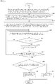
FIG. 5 is a flowchart illustrating image processing performed in an image processing apparatus. -
FIG. 6 is a schematic diagram illustrating an observation image output to a monitor. - A
vibration detection system 100 according to an embodiment will now be described with reference to the drawings. In the following description, it is assumed that thevibration detection system 100 uses anultrasonic horn 12 and a capillary 13 of awire bonding apparatus 10 as observation targets, and detects their vibrations. - To begin with, the
wire bonding apparatus 10 including theultrasonic horn 12 and thecapillary 13, which are observation targets, will be described briefly with reference toFIG. 1 . Thewire bonding apparatus 10 includes abonding arm 11, theultrasonic horn 12, thecapillary 13, anultrasonic transducer 14, and abonding stage 16. - The
capillary 13 is attached to the tip of theultrasonic horn 12, and theultrasonic transducer 14 is attached to the rear end. Theultrasonic horn 12 is caused to vibrate ultrasonically by ultrasonic vibrations generated by theultrasonic transducer 14, and causes thecapillary 13 to vibrate ultrasonically. Theultrasonic horn 12 is connected to thebonding arm 11, and is driven in a direction bringing thecapillary 13 into contact with and away from thebonding stage 16 by a driving mechanism (not illustrated). Thebonding stage 16 suctions and fixes asubstrate 18 having asemiconductor device 17 attached to its surface. In thewire bonding apparatus 10, the driving mechanism (not illustrated) presses the tip of thecapillary 13 against an electrode of thesemiconductor device 17 to bond awire 15 to the electrode of thesemiconductor device 17, and moves thecapillary 13 onto an electrode of asubstrate 18 and presses the tip of thecapillary 13 against the electrode of thesubstrate 18 to bond thewire 15 to the electrode of thesubstrate 18. In this manner, thewire bonding apparatus 10 connects the electrode of thesemiconductor device 17 and the electrode of thesubstrate 18 with aloop wire 19. Therefore, during the bonding operation, theultrasonic horn 12 and thecapillary 13 vibrate ultrasonically. Thevibration detection system 100 according to the embodiment detects and displays vibrations on a two-dimensional surface of theultrasonic horn 12 or thecapillary 13. The surfaces of theultrasonic horn 12 and thecapillary 13 are non-mirror surfaces and have small irregularities. - As illustrated in
FIG. 1 , thevibration detection system 100 includes alaser light source 20, acamera 30, and animage processing apparatus 40. - The
laser light source 20 uses a beam expander to collimate single-wavelength laser light output from a laser oscillator intoparallel laser light 21, and irradiates theultrasonic horn 12 and thecapillary 13 with theparallel laser light 21 at a single wavelength. Thecamera 30 includes animaging device 31, and captures a two-dimensional image of theultrasonic horn 12 or thecapillary 13 irradiated with theparallel laser light 21. Theimage processing apparatus 40 processes the two-dimensional image captured by thecamera 30 to identify vibrating potions, and outputs and displays two-dimensional observation images FIG. 6 ) in which the vibration portions are displayed differently from the other portions, on amonitor 50. Theimage processing apparatus 40 is a computer internally including aprocessor 41 performing information processing and amemory 42. - An operation of the
vibration detection system 100 according to the embodiment will now be described with reference toFIGS. 2 to 6 . - As illustrated in
FIG. 2 , because asurface 13a of thecapillary 13 is a non-mirror surface, and thesurface 13a has small irregularities, when thesurface 13a of thecapillary 13 is irradiated with theparallel laser light 21, thesurface 13a of thecapillary 13 reflects theparallel laser light 21 in random directions. The rays of thereflected laser light 22 due to the non-specular reflection cause interference with one another, and the reflectedlaser light 22 produces an interference pattern on the surface of theimaging device 31 of thecamera 30. - Because the interference pattern has a bright portion where rays of light intensify one another, and a dark portion where rays of light weaken one another, the
imaging device 31 of thecamera 30 acquires the interference pattern as aspotty image 13c including a large number ofbright portions 33 anddark portions 34 appeared on the surface of animage 13b of thecapillary 13, as illustrated inFIG. 3 . - Therefore, when the
camera 30 captures an image of theultrasonic horn 12 and the capillary 13, thecamera 30 acquires animage 12b of theultrasonic horn 12 with a spotty pattern and theimage 13b of thecapillary 13 with a spotty pattern, as illustrated in a field ofview 32 in FIG. 13. Theimages - The exposure time used in imaging in the
camera 30 is longer than the vibration cycles of the ultrasonic vibrations of theultrasonic horn 12 and thecapillary 13. Therefore, if theultrasonic horn 12 and thecapillary 13 vibrate ultrasonically, the areas subjected to the peaks of the vibrations shake during the exposure, as indicated byarrows image 12b of theultrasonic horn 12 and theimage 13b of thecapillary 13 on theimaging device 31, theimages ultrasonic horn 12 and thecapillary 13 vibrate ultrasonically, theimage 12b and theimage 13b on theimaging device 31 do not shake during the exposure. - In the area where the
images pixels 36 of theimaging device 31 are different from those in a still or non-vibrating condition where theultrasonic horn 12 and thecapillary 13 do not vibrate ultrasonically. As an example, in the area subjected to the peak of a vibration, the luminous intensities of thepixels 36 become greater than those when the area is not vibrating. - By contrast, when the
images images images 12a and 13b resultant of theultrasonic horn 12 and the capillary 13 being in the still or the non-vibrating condition. Therefore, in the area at the nodes of the vibration where theimages pixels 36 of theimaging device 31 remain substantially the same as those in the still or non-vibrating condition in which theultrasonic horn 12 and thecapillary 13 are not ultrasonically vibrating. - Therefore, as illustrated in
FIG. 4 , theprocessor 41 in theimage processing apparatus 40 identifies apixel 36 in which the luminous intensity has changed during the ultrasonic vibration from that during the still or non-vibrating condition, as a vibratingpixel 37. At this time, the luminous intensity is luminance detected at thepixel 36, and may be represented by, for example, a 256 grayscale ranging from 0 to 255. - The
image processing apparatus 40 identifies the vibratingpixel 37 by performing the processing to be described below, on eachpixel 36 of animage frame 35 that is an area to be applied with the image processing at once, in a two-dimensional image within the field ofview 32. In the following description, coordinates (x, y) appended after a reference numeral indicate the coordinates (x, y) of the two-dimensional image frame 35, and, for example, a pixel 36 (x, y) indicates apixel 36 at the coordinates (x, y). - As illustrated in step S101 in
FIG. 5 , theprocessor 41 in theimage processing apparatus 40 reads animage frame 35v during a period of ultrasonic vibration and animage frame 35s during a still period, from a two-dimensional image during the period of the ultrasonic vibration and from a two-dimensional image during a still or non-vibrating period, respectively, the two-dimensional images being acquired from thecamera 30 and stored in thememory 42. - As illustrated in step S102 in
FIG. 5 , theprocessor 41 calculates an average Ia (x, y) of a luminous intensity Iv (x, y) during the period of ultrasonic vibration and a luminous intensity Is (x, y) during the still period, for each of the pixels 36 (x, y).
- As indicated in step S103 in
FIG. 5 , theprocessor 41 calculates an average of the absolute values of deviations across theimage frame 35 as an absolute deviation average, the deviations being those between the luminous intensities Iv (x, y) during the period of ultrasonic vibration and the averages Ia (x, y) at the respective pixels 36 (x, y). - Absolute deviation average = average of |Iv (x, y) - Ia (x, y)| across
image frame 35 - As illustrated in step S104 in
FIG. 5 , theprocessor 41 calculates the fourth power of a normalized pixel intensity NIave (x, y) using the following (Equation 1).
- As illustrated in step S105 in
FIG. 5 , if NIave (x, y) is equal to or more than 1, theprocessor 41 determines that the change in the luminous intensity at the pixel 36 (x, y) is significant, goes to step S106 inFIG. 5 , identifies the pixel 36 (x, y) as the vibrating pixel 37 (x, y), and goes to step S107. In step S107, if it is determined that all of the pixels 36 (x, y) within theimage frame 35 have not been processed yet, theprocessor 41 goes back to step S104, and performs the processing on the next pixel 36 (x, y). By contrast, if it is determined NO in step S105 inFIG. 5 , theprocessor 41 goes back to step S104 and performs processing of the next pixel 36 (x, y). If theprocessor 41 has calculated NIave (x, y) in all of the pixels 36 (x, y) within theimage frame 35, and identified the vibrating pixel 37 (x, y) within theimage frame 35, YES is determined in step S107 inFIG. 5 , and the process goes to step S108 inFIG. 5 . - In step S108 in
FIG. 5 , theprocessor 41 checks whether there are a predetermined number of other vibrating pixels 37 (x1, y1) within a predetermined range around a vibrating pixel 37 (x, y). For example, it is possible to establish a square array consisting of 5 × 5pixels 36 having its center at the vibrating pixel 37 (x, y) as the predetermined range, and to check whether there are seven or eight other vibrating pixels 37 (x1, y1) within this square array. If it is determined as YES in step S108 inFIG. 5 , it is determined that the change in the luminous intensity at the pixel 36 (x, y) is caused by an ultrasonic vibration, and the process goes to step S109 inFIG. 5 , and maintains the pixel 36 (x, y) as a pixel identified as the vibrating pixel 37 (x, y). - By contrast, if there are no seven or eight other vibrating pixels 37 (x1, y1) in the array, it is determined that the change in the luminous intensity at the pixel 36 (x, y) is not caused by a vibration, and the process goes to step S110 in
FIG. 5 , to cancel the identification of the pixel 36 (x, y) as the vibrating pixel 37 (x, y). - The
processor 41 then finalizes the identifications of the vibrating pixels 37 (x, y). Theprocessor 41 performs the above processing on each of the image frames 35, and finalizes the identifications of the vibrating pixels 37 (x, y) across all of the pixels 36 (x, y) of theimaging device 31. - As illustrated in
FIG. 6 , theprocessor 41 then visualizes and presents the vibrations on the two-dimensional surface of theultrasonic horn 12 and the capillary 13 by outputtingobservation images ultrasonic horn 12 and the capillary 13. - The
observation images FIG. 5 , as an example,red points 52 are displayed in a manner superimposed over the parts corresponding to the vibratingpixels 37 in general images acquired by irradiating theultrasonic horn 12 and the capillary 13 with incoherent light such as electric light. According to this display method, manyred points 52 are displayed in the area at the peak of the vibration, and almost no red point is displayed in the part at the node of the vibration. In the example illustrated inFIG. 5 , it can be seen that theultrasonic horn 12, a middle part where the diameter of the capillary 13 changes, and the tip portion of the capillary 13 in which manyred points 52 are displayed have peaks of the vibrations, and the other portions correspond to the nodes of vibration. - As described above, because the
vibration detection system 100 according to the embodiment processes the two-dimensional images of theultrasonic horn 12 and the capillary 13 and displays the processed images as the two-dimensional observation images ultrasonic horn 12 and the capillary 13 in real time. - In the above description, the
vibration detection system 100 has been described to detect vibrations of theultrasonic horn 12 and thecapillary 13 of thewire bonding apparatus 10, but may also be applied to the detection of vibrations of other parts of thewire bonding apparatus 10. - For example, when the
wire bonding apparatus 10 illustrated inFIG. 1 performs bonding, vibrations of thesemiconductor device 17 may be detected by irradiating thesemiconductor device 17 with theparallel laser light 21. When the vibrations of thesemiconductor device 17 are large, it is possible to determine that the vibration energy from the capillary 13 is consumed in the vibrations other than that for bonding, and therefore, bonding is not being performed well. Similarly, it is also possible to detect whether the vibrations of thesubstrate 18 are large, and, if the vibrations of thesubstrate 18 are large, to determine that the vibration energy from the capillary 13 is consumed in the vibrations other than bonding, and therefore, bonding is not being performed well. - In addition, the
vibration detection system 100 may be applied to detections of vibrations of units included in a device other than thewire bonding apparatus 10, e.g., another semiconductor manufacturing device such as a die bonding device. - In the above description, the
laser light source 20 is described to irradiate the observation target with theparallel laser light 21 having a single wavelength, but the present invention is not limited thereto, and it is possible to use a small range of the wavelengths, or to irradiate the observation target with laser light that is not parallel light. In addition, the laser light may have some unevenness in intensity. Furthermore, in the above description, the image of the interference pattern has been described as a spotty pattern including the large number ofbright portions 33 anddark portions 34, but is not limited thereto, and may be another pattern such as a stripe pattern. - Furthermore, when the direction in which the observation target vibrates is not one direction, vibrations in a plurality of directions may be detected by preparing a plurality of
laser light sources 20 andcameras 30, irradiating the observation target with rays of laser light from a plurality of respective directions, and capturing images with therespective cameras 30 at the respective directions. -
- 10
- wire bonding apparatus
- 11
- bonding arm
- 12
- ultrasonic horn
- 12a, 13b, 13c
- images
- 12e, 13e
- observation images
- 13
- capillary
- 13a
- surface
- 14
- ultrasonic transducer
- 15
- wire
- 16
- bonding stage
- 17
- semiconductor device
- 18
- substrate
- 19
- loop wire
- 20
- laser light source
- 21
- parallel laser light
- 22
- reflected laser light
- 30
- camera
- 31
- imaging device
- 32
- field of view
- 33
- bright portion
- 34
- dark portion
- 35, 35v, 35s
- image frames
- 36
- pixel
- 37
- vibrating pixel
- 40
- image processing apparatus
- 41
- processor
- 42
- memory
- 50
- monitor
- 52
- red point
- 100
- vibration detection system
Claims (4)
- A vibration detection system that detects a vibration of an observation target having a non-mirror surface, the vibration detection system comprising:a laser light source that irradiates the observation target with laser light;a camera that includes an imaging device that captures and acquires an image of the observation target irradiated with the laser light; andan image processing apparatus that processes the image captured by the camera and that displays a vibrating potion.
- The vibration detection system according to claim 1, whereinthe camera uses an exposure time longer than a vibration cycle of the observation target at time of imaging and acquires the image as an image including an interference pattern that is formed by interference of reflections of the laser light from a surface of the observation target, andthe image processing apparatus identifies a vibrating pixel based on a deviation between an image including an interference pattern of the observation target during a non-vibrating period and an image including an interference pattern of the observation target during a vibrating period, the images being those acquired by the camera, and outputs an observation image that is an image of the observation target including an indication corresponding to the identified vibrating pixel.
- The vibration detection system according to claim 2, wherein
when there are a predetermined number of other vibrating pixels within a predetermined range around the identified vibrating pixel, the image processing apparatus maintains the pixel as a pixel identified as the vibrating pixel, and when there are no predetermined number of vibrating pixels within the predetermined range, the image processing apparatus cancels identification of the pixel as the vibrating pixel. - The vibration detection system according to claim 2 or 3, wherein
the laser light source irradiates the observation target with parallel laser light having a single wavelength.
Applications Claiming Priority (2)
| Application Number | Priority Date | Filing Date | Title |
|---|---|---|---|
| JP2019160471 | 2019-09-03 | ||
| PCT/JP2020/033353 WO2021045135A1 (en) | 2019-09-03 | 2020-09-03 | Vibration detection system |
Publications (2)
| Publication Number | Publication Date |
|---|---|
| EP4027119A1 true EP4027119A1 (en) | 2022-07-13 |
| EP4027119A4 EP4027119A4 (en) | 2023-09-06 |
Family
ID=74853220
Family Applications (1)
| Application Number | Title | Priority Date | Filing Date |
|---|---|---|---|
| EP20861869.4A Withdrawn EP4027119A4 (en) | 2019-09-03 | 2020-09-03 | VIBRATION DETECTION SYSTEM |
Country Status (7)
| Country | Link |
|---|---|
| US (1) | US20220283020A1 (en) |
| EP (1) | EP4027119A4 (en) |
| JP (1) | JP7219990B2 (en) |
| KR (1) | KR20220043202A (en) |
| CN (1) | CN113892015A (en) |
| TW (1) | TWI756811B (en) |
| WO (1) | WO2021045135A1 (en) |
Family Cites Families (31)
| Publication number | Priority date | Publication date | Assignee | Title |
|---|---|---|---|---|
| US4641527A (en) * | 1984-06-04 | 1987-02-10 | Hitachi, Ltd. | Inspection method and apparatus for joint junction states |
| US4824250A (en) * | 1986-11-17 | 1989-04-25 | Newman John W | Non-destructive testing by laser scanning |
| DE4427692A1 (en) * | 1994-08-04 | 1996-02-08 | Bayerische Motoren Werke Ag | Method for determining the vibration behavior of a body |
| JP3388034B2 (en) * | 1994-08-31 | 2003-03-17 | 株式会社東芝 | Monitoring method of equipment status using distribution measurement data |
| JPH10221159A (en) * | 1997-02-12 | 1998-08-21 | Toshiba Corp | Laser Doppler Vibration Distribution Measurement System |
| DE69934243T2 (en) * | 1998-09-01 | 2007-06-28 | Matsushita Electric Industrial Co., Ltd., Kadoma | DEVICE AND METHOD FOR EVALUATING A LOTHOCUSER COMPOSITION, AND SEMICONDUCTOR MANUFACTURING APPARATUS AND METHOD THEREFOR |
| US6128082A (en) * | 1998-09-18 | 2000-10-03 | Board Of Trustees Operating Michigan State University | Technique and apparatus for performing electronic speckle pattern interferometry |
| DE19940217C5 (en) * | 1999-08-25 | 2006-08-10 | Zwick Gmbh & Co | Method for the non-contact measurement of the change in the spatial shape of a test sample, in particular for measuring the change in length of the test sample subjected to an external force and apparatus for carrying out the method |
| US7436504B2 (en) * | 2003-09-10 | 2008-10-14 | Shear Graphics, Llc | Non-destructive testing and imaging |
| DE102007023826A1 (en) | 2007-05-21 | 2008-11-27 | Polytec Gmbh | Method and device for non-contact vibration measurement |
| WO2009022245A2 (en) * | 2007-08-10 | 2009-02-19 | Koninklijke Philips Electronics N.V. | Mechanical resonance detection system |
| CN100585328C (en) * | 2008-02-22 | 2010-01-27 | 济南大学 | Displacement measurement device and method based on laser image and corresponding pixel distance measurement |
| US20120019654A1 (en) * | 2009-01-30 | 2012-01-26 | Varun Akur Venkatesan | Measurement of vibration characteristics of an object |
| EP2375227A1 (en) * | 2010-04-09 | 2011-10-12 | Siemens Aktiengesellschaft | Measurement of three-dimensional motion characteristics |
| JP6106921B2 (en) * | 2011-04-26 | 2017-04-05 | 株式会社リコー | Imaging apparatus, imaging method, and imaging program |
| CN102889864A (en) * | 2011-07-19 | 2013-01-23 | 中铝上海铜业有限公司 | Detection system for tower shape of object with strip coil edge and detection method thereof |
| JP5974472B2 (en) | 2011-12-15 | 2016-08-23 | 日産自動車株式会社 | Wire bonding apparatus and wire bonding method |
| JP2013195287A (en) * | 2012-03-21 | 2013-09-30 | Sharp Corp | Displacement detection device, and electronic equipment |
| EP2887030B1 (en) * | 2013-12-20 | 2016-11-23 | Fraunhofer Gesellschaft zur Förderung der angewandten Forschung e.V. | Method and device for measuring oscillations of a moving object |
| CN104236464B (en) * | 2014-09-04 | 2017-03-22 | 宁波舜宇智能科技有限公司 | Laser vibration displacement sensor and measuring method thereof |
| WO2016094851A1 (en) * | 2014-12-12 | 2016-06-16 | Sunedison Semiconductor Limited | Systems and methods for performing phase shift interferometry while a wafer is vibrating |
| JP6555712B2 (en) | 2015-06-09 | 2019-08-07 | 国立大学法人 新潟大学 | Plane vibration measuring apparatus and plane vibration measuring method |
| CN105136434B (en) * | 2015-08-12 | 2019-09-20 | 中北大学 | A device for testing the law of two-dimensional motion of a planar mechanism |
| CN105258783B (en) | 2015-11-16 | 2019-01-18 | 杭州电子科技大学 | A kind of method for detecting vibration based on laser wavefront coding technology |
| CN206892031U (en) * | 2016-07-12 | 2018-01-16 | 纳路易爱姆斯株式会社 | Possess position identification flying unit and the inspection flying body of image pickup section |
| US11371878B2 (en) * | 2016-08-29 | 2022-06-28 | Elbit Systems Land And C4I Ltd. | Optical detection of vibrations |
| CN108254379B (en) * | 2016-12-28 | 2020-10-27 | 上海微电子装备(集团)股份有限公司 | A defect detection device and method |
| CN107271026B (en) * | 2017-07-07 | 2020-01-03 | 河南科技大学 | Method for measuring transverse vibration of steel wire rope |
| JP7126670B2 (en) * | 2017-09-05 | 2022-08-29 | 国立大学法人福井大学 | Defect detection method and apparatus using speckle image |
| CN107764389A (en) * | 2017-09-08 | 2018-03-06 | 天津大学 | A kind of method of low speed video camera measurement higher-frequency vibration based on fringe projection method |
| US11193887B2 (en) * | 2018-06-11 | 2021-12-07 | Shimadzu Corporation | Defect detection method and device |
-
2020
- 2020-09-02 TW TW109130081A patent/TWI756811B/en active
- 2020-09-03 US US17/626,490 patent/US20220283020A1/en not_active Abandoned
- 2020-09-03 JP JP2021544016A patent/JP7219990B2/en active Active
- 2020-09-03 KR KR1020227007729A patent/KR20220043202A/en not_active Ceased
- 2020-09-03 WO PCT/JP2020/033353 patent/WO2021045135A1/en not_active Ceased
- 2020-09-03 CN CN202080039076.9A patent/CN113892015A/en active Pending
- 2020-09-03 EP EP20861869.4A patent/EP4027119A4/en not_active Withdrawn
Also Published As
| Publication number | Publication date |
|---|---|
| TW202121551A (en) | 2021-06-01 |
| CN113892015A (en) | 2022-01-04 |
| US20220283020A1 (en) | 2022-09-08 |
| JPWO2021045135A1 (en) | 2021-03-11 |
| WO2021045135A1 (en) | 2021-03-11 |
| KR20220043202A (en) | 2022-04-05 |
| EP4027119A4 (en) | 2023-09-06 |
| TWI756811B (en) | 2022-03-01 |
| JP7219990B2 (en) | 2023-02-09 |
Similar Documents
| Publication | Publication Date | Title |
|---|---|---|
| JP2012045610A (en) | Apparatus and method for determining shape of end of bead | |
| JP7373874B2 (en) | Defect detection device and method | |
| US11790513B2 (en) | Defect inspection apparatus and defect inspection method | |
| KR101203210B1 (en) | Apparatus for inspecting defects | |
| JP5754752B2 (en) | End position detection device for strip and end position detection method for strip | |
| JP5438475B2 (en) | Gap step measurement device, gap step measurement method, and program thereof | |
| US12489992B2 (en) | Information processing apparatus, information processing method, and program | |
| KR101183179B1 (en) | Method for checking of cof appearance using laser 3d measuring machine | |
| US20220283020A1 (en) | Vibration detection system | |
| JP2020161778A (en) | Inspection equipment and inspection method | |
| KR20200081541A (en) | Imaging apparatus and driving method of the same | |
| JP2010266308A (en) | Welding workpiece shape measuring device and program for the same | |
| JP2017101977A (en) | Inspection system and inspection method | |
| JPH01113638A (en) | Recognizing apparatus | |
| JP2019207194A (en) | Inspection system and program | |
| JP2015055583A (en) | Inspection device | |
| JP2016004017A (en) | Information acquisition apparatus and image processing method | |
| JP2002310930A (en) | Bonding wire inspection device | |
| JP2007071790A (en) | MEMS operation diagnosis apparatus and operation diagnosis method | |
| JPWO2021045135A5 (en) | ||
| JP2739739B2 (en) | Misalignment inspection device | |
| JP3722369B2 (en) | Repeat pattern inspection equipment | |
| KR20260031358A (en) | AI-based vision inspection system for product appearance defect detection | |
| JP2008256484A (en) | Shape measuring device | |
| JP2000275020A (en) | Mounting condition inspection method |
Legal Events
| Date | Code | Title | Description |
|---|---|---|---|
| STAA | Information on the status of an ep patent application or granted ep patent |
Free format text: STATUS: THE INTERNATIONAL PUBLICATION HAS BEEN MADE |
|
| PUAI | Public reference made under article 153(3) epc to a published international application that has entered the european phase |
Free format text: ORIGINAL CODE: 0009012 |
|
| STAA | Information on the status of an ep patent application or granted ep patent |
Free format text: STATUS: REQUEST FOR EXAMINATION WAS MADE |
|
| 17P | Request for examination filed |
Effective date: 20220325 |
|
| AK | Designated contracting states |
Kind code of ref document: A1 Designated state(s): AL AT BE BG CH CY CZ DE DK EE ES FI FR GB GR HR HU IE IS IT LI LT LU LV MC MK MT NL NO PL PT RO RS SE SI SK SM TR |
|
| DAV | Request for validation of the european patent (deleted) | ||
| DAX | Request for extension of the european patent (deleted) | ||
| A4 | Supplementary search report drawn up and despatched |
Effective date: 20230807 |
|
| RIC1 | Information provided on ipc code assigned before grant |
Ipc: G01H 9/00 20060101AFI20230801BHEP |
|
| STAA | Information on the status of an ep patent application or granted ep patent |
Free format text: STATUS: THE APPLICATION IS DEEMED TO BE WITHDRAWN |
|
| 18D | Application deemed to be withdrawn |
Effective date: 20240305 |