EP4027114A1 - Computing device, route display device, and control system, for hybrid vehicle - Google Patents
Computing device, route display device, and control system, for hybrid vehicle Download PDFInfo
- Publication number
- EP4027114A1 EP4027114A1 EP21209945.1A EP21209945A EP4027114A1 EP 4027114 A1 EP4027114 A1 EP 4027114A1 EP 21209945 A EP21209945 A EP 21209945A EP 4027114 A1 EP4027114 A1 EP 4027114A1
- Authority
- EP
- European Patent Office
- Prior art keywords
- route
- hybrid vehicle
- zone
- computed
- vehicle
- Prior art date
- Legal status (The legal status is an assumption and is not a legal conclusion. Google has not performed a legal analysis and makes no representation as to the accuracy of the status listed.)
- Withdrawn
Links
- 238000002485 combustion reaction Methods 0.000 claims abstract description 49
- 238000004891 communication Methods 0.000 description 11
- 238000003915 air pollution Methods 0.000 description 8
- 238000010586 diagram Methods 0.000 description 8
- 238000000034 method Methods 0.000 description 8
- 230000002265 prevention Effects 0.000 description 8
- 230000007423 decrease Effects 0.000 description 7
- 230000006870 function Effects 0.000 description 4
- 230000015654 memory Effects 0.000 description 4
- 230000001172 regenerating effect Effects 0.000 description 4
- 238000012905 input function Methods 0.000 description 3
- 230000002457 bidirectional effect Effects 0.000 description 2
- 230000000694 effects Effects 0.000 description 1
- 238000005516 engineering process Methods 0.000 description 1
- 239000000446 fuel Substances 0.000 description 1
- 238000002347 injection Methods 0.000 description 1
- 239000007924 injection Substances 0.000 description 1
- 238000010248 power generation Methods 0.000 description 1
- 238000011084 recovery Methods 0.000 description 1
- 239000000243 solution Substances 0.000 description 1
- 230000000007 visual effect Effects 0.000 description 1
Images



Classifications
-
- B—PERFORMING OPERATIONS; TRANSPORTING
- B60—VEHICLES IN GENERAL
- B60W—CONJOINT CONTROL OF VEHICLE SUB-UNITS OF DIFFERENT TYPE OR DIFFERENT FUNCTION; CONTROL SYSTEMS SPECIALLY ADAPTED FOR HYBRID VEHICLES; ROAD VEHICLE DRIVE CONTROL SYSTEMS FOR PURPOSES NOT RELATED TO THE CONTROL OF A PARTICULAR SUB-UNIT
- B60W20/00—Control systems specially adapted for hybrid vehicles
- B60W20/10—Controlling the power contribution of each of the prime movers to meet required power demand
- B60W20/12—Controlling the power contribution of each of the prime movers to meet required power demand using control strategies taking into account route information
-
- G—PHYSICS
- G01—MEASURING; TESTING
- G01C—MEASURING DISTANCES, LEVELS OR BEARINGS; SURVEYING; NAVIGATION; GYROSCOPIC INSTRUMENTS; PHOTOGRAMMETRY OR VIDEOGRAMMETRY
- G01C21/00—Navigation; Navigational instruments not provided for in groups G01C1/00 - G01C19/00
- G01C21/26—Navigation; Navigational instruments not provided for in groups G01C1/00 - G01C19/00 specially adapted for navigation in a road network
- G01C21/34—Route searching; Route guidance
- G01C21/3453—Special cost functions, i.e. other than distance or default speed limit of road segments
- G01C21/3469—Fuel consumption; Energy use; Emission aspects
-
- B—PERFORMING OPERATIONS; TRANSPORTING
- B60—VEHICLES IN GENERAL
- B60W—CONJOINT CONTROL OF VEHICLE SUB-UNITS OF DIFFERENT TYPE OR DIFFERENT FUNCTION; CONTROL SYSTEMS SPECIALLY ADAPTED FOR HYBRID VEHICLES; ROAD VEHICLE DRIVE CONTROL SYSTEMS FOR PURPOSES NOT RELATED TO THE CONTROL OF A PARTICULAR SUB-UNIT
- B60W20/00—Control systems specially adapted for hybrid vehicles
- B60W20/10—Controlling the power contribution of each of the prime movers to meet required power demand
- B60W20/15—Control strategies specially adapted for achieving a particular effect
- B60W20/16—Control strategies specially adapted for achieving a particular effect for reducing engine exhaust emissions
-
- B—PERFORMING OPERATIONS; TRANSPORTING
- B60—VEHICLES IN GENERAL
- B60W—CONJOINT CONTROL OF VEHICLE SUB-UNITS OF DIFFERENT TYPE OR DIFFERENT FUNCTION; CONTROL SYSTEMS SPECIALLY ADAPTED FOR HYBRID VEHICLES; ROAD VEHICLE DRIVE CONTROL SYSTEMS FOR PURPOSES NOT RELATED TO THE CONTROL OF A PARTICULAR SUB-UNIT
- B60W50/00—Details of control systems for road vehicle drive control not related to the control of a particular sub-unit, e.g. process diagnostic or vehicle driver interfaces
- B60W50/0097—Predicting future conditions
-
- G—PHYSICS
- G01—MEASURING; TESTING
- G01C—MEASURING DISTANCES, LEVELS OR BEARINGS; SURVEYING; NAVIGATION; GYROSCOPIC INSTRUMENTS; PHOTOGRAMMETRY OR VIDEOGRAMMETRY
- G01C21/00—Navigation; Navigational instruments not provided for in groups G01C1/00 - G01C19/00
- G01C21/26—Navigation; Navigational instruments not provided for in groups G01C1/00 - G01C19/00 specially adapted for navigation in a road network
- G01C21/34—Route searching; Route guidance
- G01C21/3407—Route searching; Route guidance specially adapted for specific applications
- G01C21/3415—Dynamic re-routing, e.g. recalculating the route when the user deviates from calculated route or after detecting real-time traffic data or accidents
-
- G—PHYSICS
- G01—MEASURING; TESTING
- G01C—MEASURING DISTANCES, LEVELS OR BEARINGS; SURVEYING; NAVIGATION; GYROSCOPIC INSTRUMENTS; PHOTOGRAMMETRY OR VIDEOGRAMMETRY
- G01C21/00—Navigation; Navigational instruments not provided for in groups G01C1/00 - G01C19/00
- G01C21/26—Navigation; Navigational instruments not provided for in groups G01C1/00 - G01C19/00 specially adapted for navigation in a road network
- G01C21/34—Route searching; Route guidance
- G01C21/3453—Special cost functions, i.e. other than distance or default speed limit of road segments
- G01C21/3461—Preferred or disfavoured areas, e.g. dangerous zones, toll or emission zones, intersections, manoeuvre types or segments such as motorways, toll roads or ferries
-
- G—PHYSICS
- G01—MEASURING; TESTING
- G01C—MEASURING DISTANCES, LEVELS OR BEARINGS; SURVEYING; NAVIGATION; GYROSCOPIC INSTRUMENTS; PHOTOGRAMMETRY OR VIDEOGRAMMETRY
- G01C21/00—Navigation; Navigational instruments not provided for in groups G01C1/00 - G01C19/00
- G01C21/26—Navigation; Navigational instruments not provided for in groups G01C1/00 - G01C19/00 specially adapted for navigation in a road network
- G01C21/34—Route searching; Route guidance
- G01C21/36—Input/output arrangements for on-board computers
- G01C21/3626—Details of the output of route guidance instructions
-
- G—PHYSICS
- G08—SIGNALLING
- G08G—TRAFFIC CONTROL SYSTEMS
- G08G1/00—Traffic control systems for road vehicles
- G08G1/20—Monitoring the location of vehicles belonging to a group, e.g. fleet of vehicles, countable or determined number of vehicles
- G08G1/207—Monitoring the location of vehicles belonging to a group, e.g. fleet of vehicles, countable or determined number of vehicles with respect to certain areas, e.g. forbidden or allowed areas with possible alerting when inside or outside boundaries
-
- B—PERFORMING OPERATIONS; TRANSPORTING
- B60—VEHICLES IN GENERAL
- B60W—CONJOINT CONTROL OF VEHICLE SUB-UNITS OF DIFFERENT TYPE OR DIFFERENT FUNCTION; CONTROL SYSTEMS SPECIALLY ADAPTED FOR HYBRID VEHICLES; ROAD VEHICLE DRIVE CONTROL SYSTEMS FOR PURPOSES NOT RELATED TO THE CONTROL OF A PARTICULAR SUB-UNIT
- B60W50/00—Details of control systems for road vehicle drive control not related to the control of a particular sub-unit, e.g. process diagnostic or vehicle driver interfaces
- B60W50/08—Interaction between the driver and the control system
- B60W50/14—Means for informing the driver, warning the driver or prompting a driver intervention
- B60W2050/146—Display means
-
- B—PERFORMING OPERATIONS; TRANSPORTING
- B60—VEHICLES IN GENERAL
- B60W—CONJOINT CONTROL OF VEHICLE SUB-UNITS OF DIFFERENT TYPE OR DIFFERENT FUNCTION; CONTROL SYSTEMS SPECIALLY ADAPTED FOR HYBRID VEHICLES; ROAD VEHICLE DRIVE CONTROL SYSTEMS FOR PURPOSES NOT RELATED TO THE CONTROL OF A PARTICULAR SUB-UNIT
- B60W2510/00—Input parameters relating to a particular sub-units
- B60W2510/24—Energy storage means
- B60W2510/242—Energy storage means for electrical energy
- B60W2510/244—Charge state
-
- B—PERFORMING OPERATIONS; TRANSPORTING
- B60—VEHICLES IN GENERAL
- B60W—CONJOINT CONTROL OF VEHICLE SUB-UNITS OF DIFFERENT TYPE OR DIFFERENT FUNCTION; CONTROL SYSTEMS SPECIALLY ADAPTED FOR HYBRID VEHICLES; ROAD VEHICLE DRIVE CONTROL SYSTEMS FOR PURPOSES NOT RELATED TO THE CONTROL OF A PARTICULAR SUB-UNIT
- B60W2540/00—Input parameters relating to occupants
- B60W2540/215—Selection or confirmation of options
-
- B—PERFORMING OPERATIONS; TRANSPORTING
- B60—VEHICLES IN GENERAL
- B60W—CONJOINT CONTROL OF VEHICLE SUB-UNITS OF DIFFERENT TYPE OR DIFFERENT FUNCTION; CONTROL SYSTEMS SPECIALLY ADAPTED FOR HYBRID VEHICLES; ROAD VEHICLE DRIVE CONTROL SYSTEMS FOR PURPOSES NOT RELATED TO THE CONTROL OF A PARTICULAR SUB-UNIT
- B60W2555/00—Input parameters relating to exterior conditions, not covered by groups B60W2552/00, B60W2554/00
- B60W2555/60—Traffic rules, e.g. speed limits or right of way
-
- B—PERFORMING OPERATIONS; TRANSPORTING
- B60—VEHICLES IN GENERAL
- B60W—CONJOINT CONTROL OF VEHICLE SUB-UNITS OF DIFFERENT TYPE OR DIFFERENT FUNCTION; CONTROL SYSTEMS SPECIALLY ADAPTED FOR HYBRID VEHICLES; ROAD VEHICLE DRIVE CONTROL SYSTEMS FOR PURPOSES NOT RELATED TO THE CONTROL OF A PARTICULAR SUB-UNIT
- B60W2556/00—Input parameters relating to data
- B60W2556/45—External transmission of data to or from the vehicle
- B60W2556/50—External transmission of data to or from the vehicle of positioning data, e.g. GPS [Global Positioning System] data
Definitions
- the present disclosure relates to a computing device, a route display device, and a control system, for a hybrid vehicle.
- a hybrid vehicle which includes an electric motor for generating a driving force, a battery for supplying electric power to the electric motor, a generator for supplying electric power to the battery, and an internal combustion engine for driving the generator, in which, the internal combustion engine is operated when the remaining capacity of the battery is reduced to a lower limit capacity value, and the operation of the internal combustion engine is stopped when it is determined that the current position of the hybrid vehicle is within an enhanced air pollution prevention area (See, for example, Patent Literature 1).
- Patent Literature 1 the internal combustion engine is stopped and power generation is thus stopped when the hybrid vehicle is positioned within the enhanced air pollution prevention area.
- the remaining capacity of the battery will continue to decrease in the enhanced air pollution prevention area.
- the lower limit capacity value is set to be a large value so that the hybrid vehicle can escape from the enhanced air pollution prevention area.
- a technology for computing and displaying an optimum route from a starting point to a destination is also known.
- the optimum route is not computed in consideration of whether the route remains within the enhanced air pollution prevention area. Therefore, when the hybrid vehicle travels along the optimum route, the remaining capacity of the battery may be reduced to the operating limit quantity. In this respect, electric power required for the travel of the hybrid vehicle may not be secured, and accordingly, the hybrid vehicle may not be able to escape from the enhanced air pollution prevention area.
- the lower limit capacity value is set to be a large value in Patent Literature 1, the capacity of the battery has an upper limit, and the hybrid vehicle cannot always escape from the enhanced air pollution prevention area.
- the route display device according to configuration 2, wherein the route display device is configured to display the new route together with the computed route.
- the route display device according to configuration 2, wherein the route display device is configured to display the new route without displaying the computed route.
- the route display device according to any one of configurations 2 to 4, wherein the route display device is configured to display one of the computed route and the new route which is selected by an occupant of the hybrid vehicle, and not to display the other.
- the control system according to any one of configurations 6 to 8, wherein the route display unit is configured to display one of the computed route and the new route which is selected by an occupant of the hybrid vehicle, and not to display the other.
- Electric power required for the movement of the hybrid vehicle can be secured.
- a control system 1 for a hybrid vehicle of an embodiment according to the present disclosure includes a hybrid vehicle 10 and a server 30 outside of the hybrid vehicle 10.
- the hybrid vehicle 10 of the embodiment according to the present disclosure includes an internal combustion engine 11, a motor generator (M/G) 12, a battery 13, at least one sensor 14, a GPS receiver 15, a storage device 16, a communication device 17, and an HMI (human machine interface) 18, and an electronic control unit 20.
- M/G motor generator
- HMI human machine interface
- the internal combustion engine 11 of the embodiment according to the present disclosure is composed of, for example, a spark-ignition engine or a compression-ignition engine.
- the internal combustion engine 11 (for example, a fuel injection valve, a spark plug, a throttle valve, etc.) is controlled based on a signal from the electronic control unit 20.
- the motor generator 12 of the embodiment according to the present disclosure operates as an electric motor or a power generator.
- the motor generator 12 is controlled based on a signal from the electronic control unit 20.
- an EV operation or an HV operation is selectively performed in the hybrid vehicle 10.
- the motor generator 12 is operated as an electric motor while the internal combustion engine 11 is stopped.
- an output of the motor generator 12 is transmitted to an axle.
- the internal combustion engine 11 is operated while the motor generator 12 is operated as an electric motor.
- the output of the internal combustion engine 11 and the output of the motor generator 12 are transmitted to the axle.
- the output of the motor generator 12 is transmitted to the axle, whereas the output of the internal combustion engine 11 is transmitted to a generator (not shown) to operate the generator.
- the electric power generated by the generator is sent to the motor generator 12 or the battery 13.
- a part of the output of the internal combustion engine 11 and the output of the motor generator 12 are transmitted to the axle, and the rest of the output of the internal combustion engine 11 is transmitted to the generator.
- the electric power generated by the generator is sent to the motor generator 12 or the battery 13.
- a regenerative control operation using the motor generator 12 as a generator is performed, for example, during a deceleration operation.
- the electric power generated by the regenerative control operation is sent to the battery 13.
- the battery 13 of the embodiment according to the present disclosure is charged by electric power from the motor generator 12 operating as a generator or a generator (not shown) driven by the internal combustion engine 11. In another embodiment (not shown), the battery 13 can also be charged by an external power source. On the other hand, in the embodiment according to the present disclosure, electric power is supplied from the battery 13 to the motor generator 12 that operates as an electric motor, the electronic control unit 20, and other in-vehicle devices.
- the sensors 14 of the embodiment according to the present disclosure detect various raw data.
- the sensors 14 of the embodiment according to the present disclosure include, for example, a load sensor for detecting a required vehicle load represented by the amount of depression of an accelerator pedal, a throttle position sensor for detecting the throttle position of the internal combustion engine 11, an NOx sensor for detecting the NOx concentration in the exhaust gas of the internal combustion engine 11, a rotation speed sensor for detecting the rotation speed of the internal combustion engine 11, a voltmeter and a current meter for detecting the voltage and current of the battery 13, a speed sensor for detecting the speed of the vehicle 10, etc.
- Output signals of these sensors 14 are input to the electronic control unit 20.
- the GPS receiver 15 of the embodiment according to the present disclosure receives a signal from GPS satellites, thereby detecting information representing an absolute position (for example, longitude and latitude) of the vehicle 10.
- the position information of the vehicle 10 is input to the electronic control unit 20.
- the communication device 17 of the embodiment according to the present disclosure can be connected to a communication network N such as the Internet.
- the HMI 18 of the embodiment according to the present disclosure exchanges information between an occupant(s) (including a driver) of the vehicle 10 and the control system 1.
- the HMI 18 includes a notification function for giving, for example, visual, auditory, tactile, or olfactory notification to the occupants of the vehicle 10, and an input function for receiving inputs from the occupant of the vehicle 10.
- the HMI 18 includes, for example, a display, a lamp, a speaker, a vibrator, etc. for the notification function, and a touch panel, a button, a switch, etc. for the input function.
- the HMI 18 has the notification function without the input function.
- the electronic control unit 20 of the vehicle 10 of the embodiment according to the present disclosure includes one or more processors 21, one or more memories 22 and an input/output (I/O) port 23, which are communicably connected to one another by a bidirectional bus.
- the memories 22 include, for example, a ROM, a RAM, etc.
- Various programs are stored in the memories 22, and various functions are realized by executing these programs in the processors 21.
- the above-mentioned internal combustion engine 11, the motor generator 12, the sensors 14, the GPS receiver 15, the storage device 16, the communication device 17, and the HMI 18 are communicably connected to the input/output port 23 of the embodiment according to the present disclosure.
- the SOC or charge rate of the battery 13 is computed based on, for example, the voltage and current of the battery 13.
- the server 30 of the embodiment according to the present disclosure includes a storage device 31, a communication device 32, and an electronic control unit 40.
- the storage device 31 of the embodiment according to the present disclosure stores the position information of a predetermined restriction zone or allowable zone.
- the restriction zone and the allowable zone will be described later.
- the communication device 32 of the embodiment according to the present disclosure can be connected to the communication network N. Therefore, the vehicle 10 and the server 30 can be connected to each other via the communication network N.
- the electronic control unit 40 of the server 30 of the embodiment according to the present disclosure includes one or more processors 41, one or more memories 42 and an input/output port 43, which are communicably connected to one another by a bidirectional bus.
- the above-mentioned storage device 31 and communication device 32 are communicably connected to the input/output port 43 of the embodiment according to the present disclosure.
- a zone in which the vehicle 10 can move is divided in advance into a restriction zone in which the operation of the internal combustion engine is restricted, and an allowable zone in which the operation of the internal combustion engine is permitted.
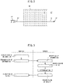
- FIG. 2 schematically shows an example of a restriction zone RZ and an example of an allowable zone AZ of the embodiment according to the present disclosure.
- the restriction zone RZ of the embodiment according to the present disclosure is surrounded by a closed boundary BD.
- the restriction zone RZ is set in, for example, an urban area.
- the operation of the internal combustion engine 11 is restricted when the vehicle 10 is located within the restriction zone RZ.
- the operation of the internal combustion engine 11 is prohibited.
- the operation of the internal combustion engine 11 is permitted.
- Restrictions for the operation of the internal combustion engine 11 in the restriction zone RZ are based on a statutory or non-statutory rule. In one example, violating this rule will result in penalties such as fines. In another example, observing this rule will give incentives such as points.
- whether the vehicle 10 is located within the restriction zone RZ or the allowable zone AZ is determined.
- the EV operation or the HV operation is performed in the vehicle 10.
- the EV operation is performed when the required output of the vehicle 10 is smaller than a predetermined set output, and the HV operation is performed when the required output is larger than the set output.
- the EV operation is performed when the SOC of the battery 13 is higher than a predetermined set SOC, and the HV operation is performed when the SOC is lower than the set SOC.
- the generator is operated by the internal combustion engine 11 so as to increase the SOC of the battery 13. This prevents the SOC of the battery 13 from falling below a lower limit value.
- the lower limit value is an SOC which makes recovery of the SOC extremely difficult if the SOC falls below the lower limit value.
- the EV operation is performed in the vehicle 10. That is, the operation of the internal combustion engine 11 is restricted.
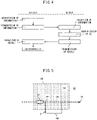
- the determination as to whether the vehicle 10 is located within the restriction zone RZ is performed, for example, as follows. That is, as shown in FIG. 3 , first, in the vehicle 10, the position information of the vehicle 10 at a current timing is acquired from the GPS receiver 15. Subsequently, the position information is transmitted from the vehicle 10 and received by the server 30. In the server 30, a restriction zone RZ in the vicinity of the vehicle 10 at the current timing is specified based on the position information of the vehicle 10, and the position information (for example, latitude and longitude) of the specified restriction zone RZ is extracted from the storage device 31. Subsequently, in the server 30, whether the vehicle 10 is located within the specified restriction zone RZ at the current timing is determined. Subsequently, a result of the determination is transmitted from the server 30 and received by the vehicle 10.
- the position information of the vehicle 10 at the current timing is acquired. Subsequently, the position information is transmitted from the vehicle 10 and received by the server 30. In the server 30, a restriction zone RZ in the vicinity of the vehicle 10 at the current timing is specified based on the position information of the vehicle 10, and the position information of the specified restriction zone RZ is extracted from the storage device 31. Subsequently, the information of the specified restriction zone RZ is transmitted from the server 30 and received by the vehicle 10. Subsequently, in the vehicle 10, whether the vehicle 10 is located within the specified restriction zone RZ at the current timing is determined.
- the position information of the restriction zone RZ is stored in the storage device 16 of the vehicle 10.
- the vehicle 10 specifies the restriction zone RZ without communicating with the server 30, and determines whether the vehicle 10 is located within the restriction zone RZ.
- a route from the current position of the vehicle 10 to the destination is computed.
- a route which makes the travel distance or travel time shortest is computed as the route.
- the computed route is displayed by the HMI 18.
- FIG. 2 shows an example of a route CR.
- a current position PP is located within the allowable zone AZ.
- the current position PP is located within the restriction zone RZ.
- a target position or destination TP is located within the allowable zone AZ.
- the destination TP is located within the restriction zone RZ.
- a part of the route CR is located within the restriction zone RZ, and the rest is located within the allowable zone AZ.
- the entirety of the route CR is located within the restriction zone RZ.
- the EV operation is performed.
- the SOC of the battery 13 continues to decline, apart from the regenerative control operation.
- the SOC of the battery 13 may decline to the above-mentioned lower limit value. Therefore, the electric power required for the movement of the vehicle 10 may not be secured, and the vehicle 10 may not be able to escape from the restriction zone RZ.
- the SOC of the battery 13 of the vehicle 10 is lower than a predetermined threshold value SOCTH (>lower limit value) while it is located within the restriction zone RZ when the vehicle 10 moves along the computed route CR , a new route NR is computed, which route is different from the computed route CR and a part of which is located within the allowable zone RZ. In other words, the route is recomputed.
- SOCTH higher limit value
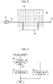
- FIG. 5 shows an example of the new route NR.
- the new route NR extends from the current position PP within the restriction zone RZ toward the allowable zone AZ, and extends within the allowable zone AZ, and thereafter, returns to the restriction zone RZ, and then extends toward the destination TP.
- the new route NR includes a portion X located within the allowable zone AZ.
- the new route NR extends from the current position PP toward the allowable zone AZ, and extends within the allowable zone AZ, and then extends toward the destination TP without returning to the restriction zone RZ.
- the HV operation can be performed when the vehicle 10 is located within the allowable zone AZ, and the SOC of the battery 13 can be increased. Therefore, it is possible to secure the electric power required for the movement of the vehicle 10.
- a new route NR is computed, which route is different from the computed route CR and at least a part of which is located within the allowable zone AZ.
- FIG. 6 shows another example of the new route NR.
- the new route NR extends from the current position PP within the allowable zone AZ toward the restriction zone RZ, and then extends toward the allowable zone AZ and extends within the allowable zone AZ, and thereafter, returns to the restriction zone RZ, and then, extends toward the destination TP.
- the new route NR includes a portion X located within the allowable zone AZ.
- the new route NR extends from the current position PP within the allowable zone AZ and extends within the allowable zone AZ, and then, enters the restriction zone RZ, and thereafter, extends toward the destination TP.
- the new route NR extends from the current position PP toward the restriction zone RZ and then toward the allowable zone AZ after extending within the restriction zone RZ, and then, extends toward the destination TP after extending within the allowable zone AZ, without returning to the restriction zone RZ.
- the new route NR extends from the current position PP toward the destination TP without entering the restriction zone RZ.
- the HV operation can be performed when the vehicle 10 is located within the allowable zone AZ, and the electric power required for the movement of the vehicle 10 can be secured.
- the new route NR of the embodiment according to the present disclosure is computed based on, for example, the current position PP, the destination TP, the position information of the restriction zone RZ, and the SOC of the battery 13, so that the SOC of the battery 13 does not decline to the lower limit value when the vehicle 10 is located within the restriction zone RZ.
- the new route NR partially matches and partially differs from the computed route CR between the current position PP and the destination TP. In another example, the new route NR is entirely different from the computed route CR.
- the destination TP is located within the allowable zone AZ. In another example, the destination TP is located within the restriction zone RZ. Further, in the example shown in FIG. 6 , the current position PP is located within the allowable zone AZ. In another example, the current position PP is located within the restriction zone RZ.
- the computed route CR may be a route which enables the vehicle 10 to reach the destination TP without reducing the SOC to the lower limit value, when the route CR was computed.
- the SOC may decline to the lower limit value due to subsequent changes of a situation. Even in such a case, according to the embodiment according to the present disclosure, the electric power required for the movement of the vehicle 10 is secured.
- the SOC of the battery 13 is predicted by, for example, integrating the decrease and increase in the SOC per unit distance or unit time.
- the decrease in the SOC is determined depending on, for example, the power consumption of the motor generator 12 operating as an electric motor, the power consumption of an air conditioner, an infotainment system, etc., and the like.
- the power consumption of the motor generator 12 is determined depending on, for example, the speed of the vehicle 10, the gradient of the road surface, and the like.
- the increase in the SOC is determined depending on, for example, the power generated by the generator, the power generated by the regenerative control operation, and the like.
- the new route NR when the new route NR is computed, at least the new route NR is displayed by the HMI 18. Specifically, in the embodiment according to the present disclosure, the new route NR is displayed together with the computed route CR. In this way, the occupants or driver of the vehicle 10 can compare the computed route CR with the new route NR
- the selected route continues to be displayed, and the unselected route stops to be displayed. That is, for example, when the new route NR is selected, the new route NR is displayed by the HMI 18, and the display of the computed route CR by the HMI 18 is stopped. As a result, the route that the occupant is trying to see is clearly displayed.
- the computed route CR and the new route NR are continuously displayed.
- the new route NR when the new route NR is computed, the new route NR is displayed without displaying the computed route CR. In other words, the route displayed by the HMI 18 is switched from the computed route CR to the new route NR
- the vehicle 10 when a new route NR is computed, the vehicle 10 moves along the new route NR. In another example, the vehicle 10 moves along one of the computed route CR and new route NR, which is selected by an occupant or operator.
- FIG. 7 shows a routine for executing a driving control operation for the vehicle 10 in the embodiment according to the present disclosure. This routine is repeatedly executed in, for example, the electronic control unit 20 of the vehicle 10.
- step 100 whether the vehicle 10 is located within the restriction zone RZ is determined.
- the process shifts from step 100 to step 101, and the EV operation is performed. That is, the operation of the internal combustion engine 11 is restricted.
- the process shifts from step 100 to step 102, and the EV operation or the HV operation is performed.
- FIG. 8 shows a routine for recomputing the route in the embodiment according to the present disclosure. This routine is repeatedly executed in, for example, the electronic control unit 20 of the vehicle 10.
- step 200 whether the vehicle 10 is moving along the computed route CR is determined. If the vehicle 10 is not moving along the computed route CR, the processing routine is terminated. When it is determined that the vehicle 10 is moving along the computed route CR, the process then shifts to step 201, and whether the vehicle 10 is located within the restriction zone RZ is determined. When it is determined that the vehicle 10 is located within the restriction zone RZ, the process then shifts to step 202, and whether the SOC of the battery 13 is lower than the threshold value SOCTH is determined. When it is determined that SOC ⁇ SOCTH, the process then shifts to step 203, and the route is recomputed. That is, the new route NR is computed.
- a route display routine is executed. This routine is shown in FIG. 9 .
- step 210 the computed route CR and the new route NR are displayed by the HMI 18.
- step 211 whether the selection of the route to be displayed has been input to the HMI 18 is determined. Step 211 is repeated until an input to the HMI 18 occurs. When the input to the HMI 18 occurs, the process shifts to step 212, and the selected route is displayed by the HMI 18.
- step 201 when it is determined at step 201 that the vehicle 10 is not located within the restriction zone RZ, and when it is determined at step 202 that SOC ⁇ SOCTH, the process then shifts to step 205.
- step 205 a predicted value SOCf of the SOC of the battery 13 when the vehicle 10 is located within the restriction zone RZ, assuming that the vehicle 10 moves along the computed route CR, is computed.
- step 206 whether the predicted value SOCf is lower than the threshold value SOCTH is determined.
- SOCf ⁇ SOCTH the process then shifts to step 203. On the contrary, when it is determined that SOCf ⁇ SOCTH, the processing cycle is terminated.
- FIG. 10 shows a functional block diagram of the vehicle 10 of the embodiment according to the present disclosure.
- the electronic control unit 20 of the vehicle 10 of the embodiment according to the present disclosure includes a position information acquisition unit 20a, a driving control unit 20b, a route recomputing unit 20c, and a route display unit 20d.
- the position information acquisition unit 20a acquires the position information of the vehicle 10 from the GPS receiver 15 and transmits it to the server 30.
- the driving control unit 20b selectively performs the EV operation or the HV operation.
- the route recomputing unit 20c determines whether a new route should be computed, and computes a new route NR when it is determined that the new route should be computed.
- the route display unit 20d displays at least the new route NR by the HMI 18 when the new route NR is computed.
- FIG. 11 shows a functional block diagram of the server 30 of the embodiment according to the present disclosure.
- the electronic control unit 40 of the server 30 of the embodiment according to the present disclosure includes a determination unit 40a.
- the determination unit 40a determines whether the vehicle 10 is located within the restriction zone RZ, and transmits a result of the determination to the vehicle 10.
- the electronic control unit 20 of the vehicle 10 further includes a determination unit similar to the determination unit 40a described above.
Landscapes
- Engineering & Computer Science (AREA)
- Radar, Positioning & Navigation (AREA)
- Remote Sensing (AREA)
- Automation & Control Theory (AREA)
- Physics & Mathematics (AREA)
- General Physics & Mathematics (AREA)
- Transportation (AREA)
- Mechanical Engineering (AREA)
- Human Computer Interaction (AREA)
- Hybrid Electric Vehicles (AREA)
- Electric Propulsion And Braking For Vehicles (AREA)
- Navigation (AREA)
Abstract
A control system (1) for a hybrid vehicle (10) with an internal combustion engine (11) and an electric motor (12) is disclosed. A zone in which the hybrid vehicle can move is divided in advance into a restriction zone RZ in which the operation of the internal combustion engine should be restricted, and an allowable zone AZ in which the operation of the internal combustion engine is permitted. A new route NR is computed if an SOC of a battery of the hybrid vehicle is lower than a predetermined threshold value while the hybrid vehicle is located within the restriction zone RZ when the hybrid vehicle moves along an initial computed route CR, or if the SOC is predicted to be lower than the threshold value while the hybrid vehicle is located within the restriction zone RZ when the hybrid vehicle is assumed to move along the initial computed route CR. The new route is different from the computed route and at least a part of the new route is located within the allowable zone. At least the new route is displayed by an HMI (118).

Description
- The present disclosure relates to a computing device, a route display device, and a control system, for a hybrid vehicle.
- It is known a hybrid vehicle, which includes an electric motor for generating a driving force, a battery for supplying electric power to the electric motor, a generator for supplying electric power to the battery, and an internal combustion engine for driving the generator, in which, the internal combustion engine is operated when the remaining capacity of the battery is reduced to a lower limit capacity value, and the operation of the internal combustion engine is stopped when it is determined that the current position of the hybrid vehicle is within an enhanced air pollution prevention area (See, for example, Patent Literature 1). In
Patent Literature 1, the internal combustion engine is stopped and power generation is thus stopped when the hybrid vehicle is positioned within the enhanced air pollution prevention area. Thus, the remaining capacity of the battery will continue to decrease in the enhanced air pollution prevention area. However, when the remaining capacity of the battery is reduced to an operating limit quantity, the hybrid vehicle can no longer travel and escape from the enhanced air pollution prevention area. Therefore, inPatent Literature 1, the lower limit capacity value is set to be a large value so that the hybrid vehicle can escape from the enhanced air pollution prevention area. - On the other hand, a technology for computing and displaying an optimum route from a starting point to a destination (navigation system) is also known.
- [PTL 1]
Japanese Unexamined Patent Publication (Kokai) No. H07(1995)-075210 - However, if the above-mentioned navigation system is combined with
Patent Literature 1, the optimum route is not computed in consideration of whether the route remains within the enhanced air pollution prevention area. Therefore, when the hybrid vehicle travels along the optimum route, the remaining capacity of the battery may be reduced to the operating limit quantity. In this respect, electric power required for the travel of the hybrid vehicle may not be secured, and accordingly, the hybrid vehicle may not be able to escape from the enhanced air pollution prevention area. Although the lower limit capacity value is set to be a large value inPatent Literature 1, the capacity of the battery has an upper limit, and the hybrid vehicle cannot always escape from the enhanced air pollution prevention area. - According to the present disclosure, the followings are provided.
- A route computing device for a hybrid vehicle equipped with an internal combustion engine and an electric motor, a zone in which the hybrid vehicle can move being divided in advance into a restriction zone in which the operation of the internal combustion engine should be restricted, and an allowable zone in which the operation of the internal combustion engine is permitted,
the route computing device being configured to compute a new route if an SOC of a battery of the hybrid vehicle is lower than a predetermined threshold value while the hybrid vehicle is located within the restriction zone when the hybrid vehicle moves along a computed route, or if the SOC is predicted to be lower than the threshold value while the hybrid vehicle is located within the restriction zone when the hybrid vehicle is assumed to move along the computed route, wherein the new route is different from the computed route and at least a part of the new route is located within the allowable zone. - A route display device for a hybrid vehicle equipped with an internal combustion engine and an electric motor, a zone in which the hybrid vehicle can move being divided in advance into a restriction zone in which the operation of the internal combustion engine should be restricted, and an allowable zone in which the operation of the internal combustion engine is permitted,
the route display device being configured to display a new route if an SOC of a battery of the hybrid vehicle is lower than a predetermined threshold value while the hybrid vehicle is located within the restriction zone when the hybrid vehicle moves along a computed route, or if the SOC is predicted to be lower than the threshold value while the hybrid vehicle is located within the restriction zone when the hybrid vehicle is assumed to move along the computed route, wherein the new route is different from the computed route and at least a part of the new route is located within the allowable zone. - The route display device according to
configuration 2, wherein the route display device is configured to display the new route together with the computed route. - The route display device according to
configuration 2, wherein the route display device is configured to display the new route without displaying the computed route. - The route display device according to any one of
configurations 2 to 4, wherein the route display device is configured to display one of the computed route and the new route which is selected by an occupant of the hybrid vehicle, and not to display the other. - A control system for a hybrid vehicle equipped with an internal combustion engine and an electric motor, a zone in which the hybrid vehicle can move being divided in advance into a restriction zone in which the operation of the internal combustion engine should be restricted, and an allowable zone in which the operation of the internal combustion engine is permitted,
- the control system comprising:
a route recomputing unit configured to compute a new route if an SOC of a battery of the hybrid vehicle is lower than a predetermined threshold value while the hybrid vehicle is located within the restriction zone when the hybrid vehicle moves along a computed route, or if the SOC is predicted to be lower than the threshold value while the hybrid vehicle is located within the restriction zone when the hybrid vehicle is assumed to move along the computed route, wherein the new route is different from the computed route and at least a part of the new route is located within the allowable zone; and - a route display unit configured to display at least the new route.
- The control system according to configuration 6, wherein the route display unit is configured to display the new route together with the computed route.
- The control system according to configuration 6, wherein the route display unit is configured to display the new route without displaying the computed route.
- The control system according to any one of configurations 6 to 8, wherein the route display unit is configured to display one of the computed route and the new route which is selected by an occupant of the hybrid vehicle, and not to display the other.
- Electric power required for the movement of the hybrid vehicle can be secured.
-
-
FIG. 1 is a schematic overall view of a control system of an embodiment according to the present disclosure. -
FIG. 2 is a schematic view of a restriction zone of an embodiment according to the present disclosure. -
FIG. 3 is a schematic diagram explaining communication between a vehicle and a server in an embodiment according to the present disclosure. -
FIG. 4 is a schematic diagram explaining communication between a vehicle and a server in another embodiment according to the present disclosure. -
FIG. 5 is a schematic diagram showing an example of a new route in an embodiment according to the present disclosure. -
FIG. 6 is a schematic diagram showing another example of the new route in the embodiment according to the present disclosure. -
FIG. 7 is a flowchart for executing a driving control routine of an embodiment according to the present disclosure. -
FIG. 8 is a flowchart for executing a route recomputing routine of an embodiment according to the present disclosure. -
FIG. 9 is a flowchart for executing a route display routine of an embodiment according to the present disclosure. -
FIG. 10 is a functional block diagram of a vehicle in an embodiment according to the present disclosure. -
FIG. 11 is a functional block diagram of a server in an embodiment according to the present disclosure. - Referring to
FIG. 1 , acontrol system 1 for a hybrid vehicle of an embodiment according to the present disclosure includes ahybrid vehicle 10 and aserver 30 outside of thehybrid vehicle 10. - The
hybrid vehicle 10 of the embodiment according to the present disclosure includes an internal combustion engine 11, a motor generator (M/G) 12, abattery 13, at least onesensor 14, aGPS receiver 15, astorage device 16, acommunication device 17, and an HMI (human machine interface) 18, and anelectronic control unit 20. - The internal combustion engine 11 of the embodiment according to the present disclosure is composed of, for example, a spark-ignition engine or a compression-ignition engine. The internal combustion engine 11 (for example, a fuel injection valve, a spark plug, a throttle valve, etc.) is controlled based on a signal from the
electronic control unit 20. - Further, the
motor generator 12 of the embodiment according to the present disclosure operates as an electric motor or a power generator. Themotor generator 12 is controlled based on a signal from theelectronic control unit 20. - In the embodiment according to the present disclosure, an EV operation or an HV operation is selectively performed in the
hybrid vehicle 10. In the EV operation of the embodiment according to the present disclosure, themotor generator 12 is operated as an electric motor while the internal combustion engine 11 is stopped. In this respect, an output of themotor generator 12 is transmitted to an axle. On the other hand, in the HV operation of the embodiment according to the present disclosure, the internal combustion engine 11 is operated while themotor generator 12 is operated as an electric motor. In this respect, in one example, the output of the internal combustion engine 11 and the output of themotor generator 12 are transmitted to the axle. In another example, the output of themotor generator 12 is transmitted to the axle, whereas the output of the internal combustion engine 11 is transmitted to a generator (not shown) to operate the generator. The electric power generated by the generator is sent to themotor generator 12 or thebattery 13. In yet another example, a part of the output of the internal combustion engine 11 and the output of themotor generator 12 are transmitted to the axle, and the rest of the output of the internal combustion engine 11 is transmitted to the generator. The electric power generated by the generator is sent to themotor generator 12 or thebattery 13. Further, in the embodiment according to the present disclosure, in the EV operation and the HV operation, a regenerative control operation using themotor generator 12 as a generator is performed, for example, during a deceleration operation. The electric power generated by the regenerative control operation is sent to thebattery 13. - The
battery 13 of the embodiment according to the present disclosure is charged by electric power from themotor generator 12 operating as a generator or a generator (not shown) driven by the internal combustion engine 11. In another embodiment (not shown), thebattery 13 can also be charged by an external power source. On the other hand, in the embodiment according to the present disclosure, electric power is supplied from thebattery 13 to themotor generator 12 that operates as an electric motor, theelectronic control unit 20, and other in-vehicle devices. - The
sensors 14 of the embodiment according to the present disclosure detect various raw data. Thesensors 14 of the embodiment according to the present disclosure include, for example, a load sensor for detecting a required vehicle load represented by the amount of depression of an accelerator pedal, a throttle position sensor for detecting the throttle position of the internal combustion engine 11, an NOx sensor for detecting the NOx concentration in the exhaust gas of the internal combustion engine 11, a rotation speed sensor for detecting the rotation speed of the internal combustion engine 11, a voltmeter and a current meter for detecting the voltage and current of thebattery 13, a speed sensor for detecting the speed of thevehicle 10, etc. Output signals of thesesensors 14 are input to theelectronic control unit 20. - The
GPS receiver 15 of the embodiment according to the present disclosure receives a signal from GPS satellites, thereby detecting information representing an absolute position (for example, longitude and latitude) of thevehicle 10. The position information of thevehicle 10 is input to theelectronic control unit 20. - Various data, in addition to map information, are stored in advance in the
storage device 16 of the embodiment according to the present disclosure. Thecommunication device 17 of the embodiment according to the present disclosure can be connected to a communication network N such as the Internet. - The
HMI 18 of the embodiment according to the present disclosure exchanges information between an occupant(s) (including a driver) of thevehicle 10 and thecontrol system 1. Specifically, theHMI 18 includes a notification function for giving, for example, visual, auditory, tactile, or olfactory notification to the occupants of thevehicle 10, and an input function for receiving inputs from the occupant of thevehicle 10. TheHMI 18 includes, for example, a display, a lamp, a speaker, a vibrator, etc. for the notification function, and a touch panel, a button, a switch, etc. for the input function. In another embodiment (not shown), theHMI 18 has the notification function without the input function. - The
electronic control unit 20 of thevehicle 10 of the embodiment according to the present disclosure includes one ormore processors 21, one ormore memories 22 and an input/output (I/O)port 23, which are communicably connected to one another by a bidirectional bus. Thememories 22 include, for example, a ROM, a RAM, etc. Various programs are stored in thememories 22, and various functions are realized by executing these programs in theprocessors 21. The above-mentioned internal combustion engine 11, themotor generator 12, thesensors 14, theGPS receiver 15, thestorage device 16, thecommunication device 17, and theHMI 18 are communicably connected to the input/output port 23 of the embodiment according to the present disclosure. Further, in theprocessors 21 of the embodiment according to the present disclosure, the SOC or charge rate of thebattery 13 is computed based on, for example, the voltage and current of thebattery 13. - Further, referring to
FIG. 1 , theserver 30 of the embodiment according to the present disclosure includes astorage device 31, acommunication device 32, and anelectronic control unit 40. - The
storage device 31 of the embodiment according to the present disclosure stores the position information of a predetermined restriction zone or allowable zone. The restriction zone and the allowable zone will be described later. - The
communication device 32 of the embodiment according to the present disclosure can be connected to the communication network N. Therefore, thevehicle 10 and theserver 30 can be connected to each other via the communication network N. - As in the
electronic control unit 20 of thevehicle 10, theelectronic control unit 40 of theserver 30 of the embodiment according to the present disclosure includes one ormore processors 41, one ormore memories 42 and an input/output port 43, which are communicably connected to one another by a bidirectional bus. The above-mentionedstorage device 31 andcommunication device 32 are communicably connected to the input/output port 43 of the embodiment according to the present disclosure. - In the embodiment according to the present disclosure, a zone in which the
vehicle 10 can move is divided in advance into a restriction zone in which the operation of the internal combustion engine is restricted, and an allowable zone in which the operation of the internal combustion engine is permitted.FIG. 2 schematically shows an example of a restriction zone RZ and an example of an allowable zone AZ of the embodiment according to the present disclosure. The restriction zone RZ of the embodiment according to the present disclosure is surrounded by a closed boundary BD. The restriction zone RZ is set in, for example, an urban area. - That is, in the embodiment according to the present disclosure, the operation of the internal combustion engine 11 is restricted when the
vehicle 10 is located within the restriction zone RZ. In one example, the operation of the internal combustion engine 11 is prohibited. On the contrary, when thevehicle 10 is located within the allowable zone AZ, the operation of the internal combustion engine 11 is permitted. - Restrictions for the operation of the internal combustion engine 11 in the restriction zone RZ are based on a statutory or non-statutory rule. In one example, violating this rule will result in penalties such as fines. In another example, observing this rule will give incentives such as points.
- In the embodiment according to the present disclosure, whether the
vehicle 10 is located within the restriction zone RZ or the allowable zone AZ is determined. - When it is determined that the
vehicle 10 is located within the allowable zone AZ, the EV operation or the HV operation is performed in thevehicle 10. In one example, the EV operation is performed when the required output of thevehicle 10 is smaller than a predetermined set output, and the HV operation is performed when the required output is larger than the set output. Further, the EV operation is performed when the SOC of thebattery 13 is higher than a predetermined set SOC, and the HV operation is performed when the SOC is lower than the set SOC. In the HV operation in this respect, the generator is operated by the internal combustion engine 11 so as to increase the SOC of thebattery 13. This prevents the SOC of thebattery 13 from falling below a lower limit value. Note that the lower limit value is an SOC which makes recovery of the SOC extremely difficult if the SOC falls below the lower limit value. - On the contrary, when it is determined that the
vehicle 10 is located within the restriction zone RZ, the EV operation is performed in thevehicle 10. That is, the operation of the internal combustion engine 11 is restricted. - In the embodiment according to the present disclosure, the determination as to whether the
vehicle 10 is located within the restriction zone RZ is performed, for example, as follows. That is, as shown inFIG. 3 , first, in thevehicle 10, the position information of thevehicle 10 at a current timing is acquired from theGPS receiver 15. Subsequently, the position information is transmitted from thevehicle 10 and received by theserver 30. In theserver 30, a restriction zone RZ in the vicinity of thevehicle 10 at the current timing is specified based on the position information of thevehicle 10, and the position information (for example, latitude and longitude) of the specified restriction zone RZ is extracted from thestorage device 31. Subsequently, in theserver 30, whether thevehicle 10 is located within the specified restriction zone RZ at the current timing is determined. Subsequently, a result of the determination is transmitted from theserver 30 and received by thevehicle 10. - On the contrary, in another embodiment shown in
FIG. 4 , first, in thevehicle 10, the position information of thevehicle 10 at the current timing is acquired. Subsequently, the position information is transmitted from thevehicle 10 and received by theserver 30. In theserver 30, a restriction zone RZ in the vicinity of thevehicle 10 at the current timing is specified based on the position information of thevehicle 10, and the position information of the specified restriction zone RZ is extracted from thestorage device 31. Subsequently, the information of the specified restriction zone RZ is transmitted from theserver 30 and received by thevehicle 10. Subsequently, in thevehicle 10, whether thevehicle 10 is located within the specified restriction zone RZ at the current timing is determined. - In yet another embodiment, the position information of the restriction zone RZ is stored in the
storage device 16 of thevehicle 10. In this respect, thevehicle 10 specifies the restriction zone RZ without communicating with theserver 30, and determines whether thevehicle 10 is located within the restriction zone RZ. - On the other hand, in the embodiment according to the present disclosure, when a destination is input via the
HMI 18, a route from the current position of thevehicle 10 to the destination is computed. In one example, a route which makes the travel distance or travel time shortest, is computed as the route. In the embodiment according to the present disclosure, the computed route is displayed by theHMI 18. -
FIG. 2 shows an example of a route CR. In the example shown inFIG. 2 , a current position PP is located within the allowable zone AZ. In another example, the current position PP is located within the restriction zone RZ. Further, in the example shown inFIG. 2 , a target position or destination TP is located within the allowable zone AZ. In another example, the destination TP is located within the restriction zone RZ. Further, in the example shown inFIG. 2 , a part of the route CR is located within the restriction zone RZ, and the rest is located within the allowable zone AZ. In another example, the entirety of the route CR is located within the restriction zone RZ. - By the way, in the embodiment according to the present disclosure, as described above, when it is determined that the
vehicle 10 is located within the restriction zone RZ, the EV operation is performed. As thevehicle 10 continuously moves within the restriction zone RZ, the SOC of thebattery 13 continues to decline, apart from the regenerative control operation. Thus, the SOC of thebattery 13 may decline to the above-mentioned lower limit value. Therefore, the electric power required for the movement of thevehicle 10 may not be secured, and thevehicle 10 may not be able to escape from the restriction zone RZ. - Therefore, in the embodiment according to the present disclosure, if the SOC of the
battery 13 of thevehicle 10 is lower than a predetermined threshold value SOCTH (>lower limit value) while it is located within the restriction zone RZ when thevehicle 10 moves along the computed route CR , a new route NR is computed, which route is different from the computed route CR and a part of which is located within the allowable zone RZ. In other words, the route is recomputed. -
FIG. 5 shows an example of the new route NR. In the example shown inFIG. 5 , the new route NR extends from the current position PP within the restriction zone RZ toward the allowable zone AZ, and extends within the allowable zone AZ, and thereafter, returns to the restriction zone RZ, and then extends toward the destination TP. Thus, the new route NR includes a portion X located within the allowable zone AZ. In another example, the new route NR extends from the current position PP toward the allowable zone AZ, and extends within the allowable zone AZ, and then extends toward the destination TP without returning to the restriction zone RZ. - As a result, if the
vehicle 10 moves along the new route NR, the HV operation can be performed when thevehicle 10 is located within the allowable zone AZ, and the SOC of thebattery 13 can be increased. Therefore, it is possible to secure the electric power required for the movement of thevehicle 10. - Further, in the embodiment according to the present disclosure, if the SOC of the
battery 13 is predicted to be lower than the threshold value SOCTH while thevehicle 10 is located within the restriction zone RZ when thevehicle 10 is assumed to move along the computed route CR, a new route NR is computed, which route is different from the computed route CR and at least a part of which is located within the allowable zone AZ. -
FIG. 6 shows another example of the new route NR. In the example shown inFIG. 6 , the new route NR extends from the current position PP within the allowable zone AZ toward the restriction zone RZ, and then extends toward the allowable zone AZ and extends within the allowable zone AZ, and thereafter, returns to the restriction zone RZ, and then, extends toward the destination TP. Thus, the new route NR includes a portion X located within the allowable zone AZ. - In another example, the new route NR extends from the current position PP within the allowable zone AZ and extends within the allowable zone AZ, and then, enters the restriction zone RZ, and thereafter, extends toward the destination TP. In yet another example, the new route NR extends from the current position PP toward the restriction zone RZ and then toward the allowable zone AZ after extending within the restriction zone RZ, and then, extends toward the destination TP after extending within the allowable zone AZ, without returning to the restriction zone RZ. In yet another example, the new route NR extends from the current position PP toward the destination TP without entering the restriction zone RZ.
- As a result, also in this respect, if the
vehicle 10 moves along the new route NR, the HV operation can be performed when thevehicle 10 is located within the allowable zone AZ, and the electric power required for the movement of thevehicle 10 can be secured. - The new route NR of the embodiment according to the present disclosure is computed based on, for example, the current position PP, the destination TP, the position information of the restriction zone RZ, and the SOC of the
battery 13, so that the SOC of thebattery 13 does not decline to the lower limit value when thevehicle 10 is located within the restriction zone RZ. - In the examples shown in
FIGS. 5 and6 , the new route NR partially matches and partially differs from the computed route CR between the current position PP and the destination TP. In another example, the new route NR is entirely different from the computed route CR. Further, in the examples shown inFIGS. 5 and6 , the destination TP is located within the allowable zone AZ. In another example, the destination TP is located within the restriction zone RZ. Further, in the example shown inFIG. 6 , the current position PP is located within the allowable zone AZ. In another example, the current position PP is located within the restriction zone RZ. - The computed route CR may be a route which enables the
vehicle 10 to reach the destination TP without reducing the SOC to the lower limit value, when the route CR was computed. However, the SOC may decline to the lower limit value due to subsequent changes of a situation. Even in such a case, according to the embodiment according to the present disclosure, the electric power required for the movement of thevehicle 10 is secured. - Note that the SOC of the
battery 13 is predicted by, for example, integrating the decrease and increase in the SOC per unit distance or unit time. The decrease in the SOC is determined depending on, for example, the power consumption of themotor generator 12 operating as an electric motor, the power consumption of an air conditioner, an infotainment system, etc., and the like. The power consumption of themotor generator 12 is determined depending on, for example, the speed of thevehicle 10, the gradient of the road surface, and the like. The increase in the SOC is determined depending on, for example, the power generated by the generator, the power generated by the regenerative control operation, and the like. - On the other hand, in the embodiment according to the present disclosure, when the new route NR is computed, at least the new route NR is displayed by the
HMI 18. Specifically, in the embodiment according to the present disclosure, the new route NR is displayed together with the computed route CR. In this way, the occupants or driver of thevehicle 10 can compare the computed route CR with the new route NR - In the embodiment according to the present disclosure, subsequently, when the occupant of the
vehicle 10 selects one of the computed route CR and the new route NR via theHMI 18, the selected route continues to be displayed, and the unselected route stops to be displayed. That is, for example, when the new route NR is selected, the new route NR is displayed by theHMI 18, and the display of the computed route CR by theHMI 18 is stopped. As a result, the route that the occupant is trying to see is clearly displayed. - In another example, when the new route NR is computed, the computed route CR and the new route NR are continuously displayed.
- In yet another example, when the new route NR is computed, the new route NR is displayed without displaying the computed route CR. In other words, the route displayed by the
HMI 18 is switched from the computed route CR to the new route NR - Note that, in the case where the
vehicle 10 is a self-driving vehicle, in one example, when a new route NR is computed, thevehicle 10 moves along the new route NR. In another example, thevehicle 10 moves along one of the computed route CR and new route NR, which is selected by an occupant or operator. -
FIG. 7 shows a routine for executing a driving control operation for thevehicle 10 in the embodiment according to the present disclosure. This routine is repeatedly executed in, for example, theelectronic control unit 20 of thevehicle 10. - Referring to
FIG. 7 , first, atstep 100, whether thevehicle 10 is located within the restriction zone RZ is determined. When it is determined that thevehicle 10 is located within the restriction zone RZ, the process shifts fromstep 100 to step 101, and the EV operation is performed. That is, the operation of the internal combustion engine 11 is restricted. On the contrary, when it is determined that thevehicle 10 is located within the allowable zone AZ, the process shifts fromstep 100 to step 102, and the EV operation or the HV operation is performed. -
FIG. 8 shows a routine for recomputing the route in the embodiment according to the present disclosure. This routine is repeatedly executed in, for example, theelectronic control unit 20 of thevehicle 10. - Referring to
FIG. 8 , first, atstep 200, whether thevehicle 10 is moving along the computed route CR is determined. If thevehicle 10 is not moving along the computed route CR, the processing routine is terminated. When it is determined that thevehicle 10 is moving along the computed route CR, the process then shifts to step 201, and whether thevehicle 10 is located within the restriction zone RZ is determined. When it is determined that thevehicle 10 is located within the restriction zone RZ, the process then shifts to step 202, and whether the SOC of thebattery 13 is lower than the threshold value SOCTH is determined. When it is determined that SOC<SOCTH, the process then shifts to step 203, and the route is recomputed. That is, the new route NR is computed. At the followingstep 204, a route display routine is executed. This routine is shown inFIG. 9 . - Referring to
FIG. 9 , atstep 210, the computed route CR and the new route NR are displayed by theHMI 18. At the followingstep 211, whether the selection of the route to be displayed has been input to theHMI 18 is determined. Step 211 is repeated until an input to theHMI 18 occurs. When the input to theHMI 18 occurs, the process shifts to step 212, and the selected route is displayed by theHMI 18. - Referring again to
FIG. 8 , when it is determined atstep 201 that thevehicle 10 is not located within the restriction zone RZ, and when it is determined atstep 202 that SOC≥SOCTH, the process then shifts to step 205. Atstep 205, a predicted value SOCf of the SOC of thebattery 13 when thevehicle 10 is located within the restriction zone RZ, assuming that thevehicle 10 moves along the computed route CR, is computed. At the followingstep 206, whether the predicted value SOCf is lower than the threshold value SOCTH is determined. When it is determined that SOCf<SOCTH, the process then shifts to step 203. On the contrary, when it is determined that SOCf≥SOCTH, the processing cycle is terminated. -
FIG. 10 shows a functional block diagram of thevehicle 10 of the embodiment according to the present disclosure. Referring toFIG. 10 , theelectronic control unit 20 of thevehicle 10 of the embodiment according to the present disclosure includes a positioninformation acquisition unit 20a, a drivingcontrol unit 20b, aroute recomputing unit 20c, and aroute display unit 20d. - In the example shown in
FIG. 10 , the positioninformation acquisition unit 20a acquires the position information of thevehicle 10 from theGPS receiver 15 and transmits it to theserver 30. The drivingcontrol unit 20b selectively performs the EV operation or the HV operation. Theroute recomputing unit 20c determines whether a new route should be computed, and computes a new route NR when it is determined that the new route should be computed. Theroute display unit 20d displays at least the new route NR by theHMI 18 when the new route NR is computed. - On the other hand,
FIG. 11 shows a functional block diagram of theserver 30 of the embodiment according to the present disclosure. Referring toFIG. 11 , theelectronic control unit 40 of theserver 30 of the embodiment according to the present disclosure includes adetermination unit 40a. In the example shown inFIG. 11 , thedetermination unit 40a determines whether thevehicle 10 is located within the restriction zone RZ, and transmits a result of the determination to thevehicle 10. - In another embodiment shown in
FIG. 5 , theelectronic control unit 20 of thevehicle 10 further includes a determination unit similar to thedetermination unit 40a described above. - This application claims the benefit of
Japanese Patent Application No. 2020-214196 -
- 1
- control system
- 10
- hybrid vehicle
- 11
- internal combustion engine
- 12
- motor generator
- 20
- electronic control unit of vehicle
- 30
- server
- 40
- electronic control unit of server
Claims (9)
- A route computing device for a hybrid vehicle equipped with an internal combustion engine and an electric motor, a zone in which the hybrid vehicle can move being divided in advance into a restriction zone in which the operation of the internal combustion engine should be restricted, and an allowable zone in which the operation of the internal combustion engine is permitted,
the route computing device being configured to compute a new route if an SOC of a battery of the hybrid vehicle is lower than a predetermined threshold value while the hybrid vehicle is located within the restriction zone when the hybrid vehicle moves along a computed route, or if the SOC is predicted to be lower than the threshold value while the hybrid vehicle is located within the restriction zone when the hybrid vehicle is assumed to move along the computed route, wherein the new route is different from the computed route and at least a part of the new route is located within the allowable zone. - A route display device for a hybrid vehicle equipped with an internal combustion engine and an electric motor, a zone in which the hybrid vehicle can move being divided in advance into a restriction zone in which the operation of the internal combustion engine should be restricted, and an allowable zone in which the operation of the internal combustion engine is permitted,
the route display device being configured to display a new route if an SOC of a battery of the hybrid vehicle is lower than a predetermined threshold value while the hybrid vehicle is located within the restriction zone when the hybrid vehicle moves along a computed route, or if the SOC is predicted to be lower than the threshold value while the hybrid vehicle is located within the restriction zone when the hybrid vehicle is assumed to move along the computed route, wherein the new route is different from the computed route and at least a part of the new route is located within the allowable zone. - The route display device according to claim 2, wherein the route display device is configured to display the new route together with the computed route.
- The route display device according to claim 2, wherein the route display device is configured to display the new route without displaying the computed route.
- The route display device according to any one of claims 2 to 4, wherein the route display device is configured to display one of the computed route and the new route which is selected by an occupant of the hybrid vehicle, and not to display the other.
- A control system for a hybrid vehicle equipped with an internal combustion engine and an electric motor, a zone in which the hybrid vehicle can move being divided in advance into a restriction zone in which the operation of the internal combustion engine should be restricted, and an allowable zone in which the operation of the internal combustion engine is permitted,the control system comprising:
a route recomputing unit configured to compute a new route if an SOC of a battery of the hybrid vehicle is lower than a predetermined threshold value while the hybrid vehicle is located within the restriction zone when the hybrid vehicle moves along a computed route, or if the SOC is predicted to be lower than the threshold value while the hybrid vehicle is located within the restriction zone when the hybrid vehicle is assumed to move along the computed route, wherein the new route is different from the computed route and at least a part of the new route is located within the allowable zone; anda route display unit configured to display at least the new route. - The control system according to claim 6, wherein the route display unit is configured to display the new route together with the computed route.
- The control system according to claim 6, wherein the route display unit is configured to display the new route without displaying the computed route.
- The control system according to any one of claims 6 to 8, wherein the route display unit is configured to display one of the computed route and the new route which is selected by an occupant of the hybrid vehicle, and not to display the other.
Applications Claiming Priority (1)
| Application Number | Priority Date | Filing Date | Title |
|---|---|---|---|
| JP2020214196A JP2022100059A (en) | 2020-12-23 | 2020-12-23 | Calculation device, route display device and control system for hybrid vehicle |
Publications (1)
| Publication Number | Publication Date |
|---|---|
| EP4027114A1 true EP4027114A1 (en) | 2022-07-13 |
Family
ID=78770493
Family Applications (1)
| Application Number | Title | Priority Date | Filing Date |
|---|---|---|---|
| EP21209945.1A Withdrawn EP4027114A1 (en) | 2020-12-23 | 2021-11-23 | Computing device, route display device, and control system, for hybrid vehicle |
Country Status (4)
| Country | Link |
|---|---|
| US (1) | US20220196420A1 (en) |
| EP (1) | EP4027114A1 (en) |
| JP (1) | JP2022100059A (en) |
| CN (1) | CN114655188A (en) |
Citations (5)
| Publication number | Priority date | Publication date | Assignee | Title |
|---|---|---|---|---|
| JPH0775210A (en) | 1993-09-06 | 1995-03-17 | Mitsubishi Motors Corp | Hybrid electric vehicle |
| EP1297982A2 (en) * | 2001-09-28 | 2003-04-02 | Pioneer Corporation | Hybrid car with navigation system for emission reduction |
| US20120290149A1 (en) * | 2011-05-09 | 2012-11-15 | Ford Global Technologies, Llc | Methods and Apparatus for Selective Power Enablement with Predictive Capability |
| DE102017004690A1 (en) * | 2017-05-16 | 2018-11-22 | GM Global Technology Operations LLC (n. d. Ges. d. Staates Delaware) | System for optimizing pollutant emissions from hybrid vehicles |
| EP3480046A1 (en) * | 2017-11-01 | 2019-05-08 | Hyundai Motor Company | Hybrid electric vehicle and method of controlling engine operation for the same |
Family Cites Families (13)
| Publication number | Priority date | Publication date | Assignee | Title |
|---|---|---|---|---|
| US6483198B2 (en) * | 2001-01-19 | 2002-11-19 | Transportation Techniques Llc | Hybrid electric vehicle having a selective zero emission mode, and method of selectively operating the zero emission mode |
| JP4927016B2 (en) * | 2008-03-31 | 2012-05-09 | トヨタ自動車株式会社 | Navigation system and hybrid vehicle equipped with the same |
| JP2010125868A (en) * | 2008-11-25 | 2010-06-10 | Denso Corp | Charge and discharge planning device |
| US8942919B2 (en) * | 2010-10-27 | 2015-01-27 | Honda Motor Co., Ltd. | BEV routing system and method |
| FR2992930B1 (en) * | 2012-07-06 | 2014-07-04 | Renault Sa | METHOD OF USING A HYBRID PROPULSION SYSTEM OF A VEHICLE |
| DE102012214252B4 (en) * | 2012-08-10 | 2024-05-16 | Robert Bosch Gmbh | Method for controlling the operation of a hybrid vehicle and hybrid vehicle with a control system operable according to this method |
| GB2509994A (en) * | 2013-01-22 | 2014-07-23 | Daimler Ag | Vehicle operation with energy consumption adjustment |
| US9821790B2 (en) * | 2015-12-17 | 2017-11-21 | Jaguar Land Rover Limited | System and method to facilitate satisfying low emission zone requirements |
| JP6375568B2 (en) * | 2016-04-28 | 2018-08-22 | 本田技研工業株式会社 | Vehicle control system, vehicle control method, and vehicle control program |
| US10744892B2 (en) * | 2017-11-15 | 2020-08-18 | Ford Global Technologies, Llc | System and method for battery charging |
| KR102569895B1 (en) * | 2018-06-25 | 2023-08-23 | 현대자동차주식회사 | Hybrid vehicle and method of driving control for the same |
| KR102524295B1 (en) * | 2018-11-26 | 2023-04-21 | 현대자동차주식회사 | Plug-in hybrid vehicle and method of charging control for the same |
| US11041734B2 (en) * | 2019-03-07 | 2021-06-22 | Ford Global Technologies, Llc | Systems and methods for optimizing a travel route of a hybrid-electric vehicle inside an emissions-free zone |
-
2020
- 2020-12-23 JP JP2020214196A patent/JP2022100059A/en not_active Withdrawn
-
2021
- 2021-11-23 EP EP21209945.1A patent/EP4027114A1/en not_active Withdrawn
- 2021-12-15 CN CN202111533497.XA patent/CN114655188A/en active Pending
- 2021-12-21 US US17/557,077 patent/US20220196420A1/en not_active Abandoned
Patent Citations (5)
| Publication number | Priority date | Publication date | Assignee | Title |
|---|---|---|---|---|
| JPH0775210A (en) | 1993-09-06 | 1995-03-17 | Mitsubishi Motors Corp | Hybrid electric vehicle |
| EP1297982A2 (en) * | 2001-09-28 | 2003-04-02 | Pioneer Corporation | Hybrid car with navigation system for emission reduction |
| US20120290149A1 (en) * | 2011-05-09 | 2012-11-15 | Ford Global Technologies, Llc | Methods and Apparatus for Selective Power Enablement with Predictive Capability |
| DE102017004690A1 (en) * | 2017-05-16 | 2018-11-22 | GM Global Technology Operations LLC (n. d. Ges. d. Staates Delaware) | System for optimizing pollutant emissions from hybrid vehicles |
| EP3480046A1 (en) * | 2017-11-01 | 2019-05-08 | Hyundai Motor Company | Hybrid electric vehicle and method of controlling engine operation for the same |
Also Published As
| Publication number | Publication date |
|---|---|
| US20220196420A1 (en) | 2022-06-23 |
| JP2022100059A (en) | 2022-07-05 |
| CN114655188A (en) | 2022-06-24 |
Similar Documents
| Publication | Publication Date | Title |
|---|---|---|
| EP2172740B1 (en) | Map display device, map display method, and computer readable tangible medium | |
| US20220001852A1 (en) | Control system and control method for hybrid vehicle | |
| US9200917B2 (en) | Vehicle control device | |
| US8207838B2 (en) | Eco-drive assist apparatus and method | |
| KR20090057330A (en) | Recording medium recording a program and a program for causing the computer to control the vehicle, the method of controlling the vehicle, and the method of controlling the vehicle | |
| CN114084152B (en) | Data collection device for machine learning | |
| US11370451B2 (en) | Information providing system and information providing method | |
| US20090105925A1 (en) | Vehicle travel history provision system | |
| JP5387152B2 (en) | Vehicle travel control device | |
| US20220089145A1 (en) | Control system for and control method of hybrid vehicle | |
| US11059484B2 (en) | Driving assistance device, vehicle driving assistance system, control method of driving assistance device, and non-transitory recording medium storing program | |
| EP4027114A1 (en) | Computing device, route display device, and control system, for hybrid vehicle | |
| US11573092B2 (en) | Control system and control method for hybrid vehicle | |
| JP7533311B2 (en) | Hybrid vehicle control system and control method | |
| EP4039553A1 (en) | Alarm device, alarm system, and gate device, adapted for hybrid vehicle | |
| CN110466500A (en) | Vehicle control system, control method for vehicle and storage medium | |
| US11708064B2 (en) | Hybrid vehicle | |
| JP5334661B2 (en) | Vehicle driving support device | |
| JP2022175288A (en) | Hybrid-vehicular control system | |
| US12272191B2 (en) | Display control device, display control method, and display control program | |
| JP2022135017A (en) | Hybrid-vehicular control apparatus | |
| JP2023070422A (en) | Hybrid vehicle control device | |
| JP2022167643A (en) | Control device of hybrid vehicle | |
| JP2023181728A (en) | Vehicle control device | |
| JP2023045087A (en) | driving support system |
Legal Events
| Date | Code | Title | Description |
|---|---|---|---|
| PUAI | Public reference made under article 153(3) epc to a published international application that has entered the european phase |
Free format text: ORIGINAL CODE: 0009012 |
|
| STAA | Information on the status of an ep patent application or granted ep patent |
Free format text: STATUS: REQUEST FOR EXAMINATION WAS MADE |
|
| 17P | Request for examination filed |
Effective date: 20211208 |
|
| AK | Designated contracting states |
Kind code of ref document: A1 Designated state(s): AL AT BE BG CH CY CZ DE DK EE ES FI FR GB GR HR HU IE IS IT LI LT LU LV MC MK MT NL NO PL PT RO RS SE SI SK SM TR |
|
| STAA | Information on the status of an ep patent application or granted ep patent |
Free format text: STATUS: THE APPLICATION IS DEEMED TO BE WITHDRAWN |
|
| 18D | Application deemed to be withdrawn |
Effective date: 20230114 |