EP4027075A1 - Carbon dioxide refrigeration system with low temperature mode - Google Patents
Carbon dioxide refrigeration system with low temperature mode Download PDFInfo
- Publication number
- EP4027075A1 EP4027075A1 EP21150423.8A EP21150423A EP4027075A1 EP 4027075 A1 EP4027075 A1 EP 4027075A1 EP 21150423 A EP21150423 A EP 21150423A EP 4027075 A1 EP4027075 A1 EP 4027075A1
- Authority
- EP
- European Patent Office
- Prior art keywords
- refrigeration system
- ejector
- heat exchanger
- bypass
- outlet
- Prior art date
- Legal status (The legal status is an assumption and is not a legal conclusion. Google has not performed a legal analysis and makes no representation as to the accuracy of the status listed.)
- Granted
Links
Images

Classifications
-
- F—MECHANICAL ENGINEERING; LIGHTING; HEATING; WEAPONS; BLASTING
- F25—REFRIGERATION OR COOLING; COMBINED HEATING AND REFRIGERATION SYSTEMS; HEAT PUMP SYSTEMS; MANUFACTURE OR STORAGE OF ICE; LIQUEFACTION SOLIDIFICATION OF GASES
- F25B—REFRIGERATION MACHINES, PLANTS OR SYSTEMS; COMBINED HEATING AND REFRIGERATION SYSTEMS; HEAT PUMP SYSTEMS
- F25B9/00—Compression machines, plants or systems, in which the refrigerant is air or other gas of low boiling point
- F25B9/002—Compression machines, plants or systems, in which the refrigerant is air or other gas of low boiling point characterised by the refrigerant
- F25B9/008—Compression machines, plants or systems, in which the refrigerant is air or other gas of low boiling point characterised by the refrigerant the refrigerant being carbon dioxide
-
- F—MECHANICAL ENGINEERING; LIGHTING; HEATING; WEAPONS; BLASTING
- F25—REFRIGERATION OR COOLING; COMBINED HEATING AND REFRIGERATION SYSTEMS; HEAT PUMP SYSTEMS; MANUFACTURE OR STORAGE OF ICE; LIQUEFACTION SOLIDIFICATION OF GASES
- F25B—REFRIGERATION MACHINES, PLANTS OR SYSTEMS; COMBINED HEATING AND REFRIGERATION SYSTEMS; HEAT PUMP SYSTEMS
- F25B41/00—Fluid-circulation arrangements
- F25B41/20—Disposition of valves, e.g. of on-off valves or flow control valves
-
- F—MECHANICAL ENGINEERING; LIGHTING; HEATING; WEAPONS; BLASTING
- F25—REFRIGERATION OR COOLING; COMBINED HEATING AND REFRIGERATION SYSTEMS; HEAT PUMP SYSTEMS; MANUFACTURE OR STORAGE OF ICE; LIQUEFACTION SOLIDIFICATION OF GASES
- F25B—REFRIGERATION MACHINES, PLANTS OR SYSTEMS; COMBINED HEATING AND REFRIGERATION SYSTEMS; HEAT PUMP SYSTEMS
- F25B41/00—Fluid-circulation arrangements
- F25B41/30—Expansion means; Dispositions thereof
-
- F—MECHANICAL ENGINEERING; LIGHTING; HEATING; WEAPONS; BLASTING
- F25—REFRIGERATION OR COOLING; COMBINED HEATING AND REFRIGERATION SYSTEMS; HEAT PUMP SYSTEMS; MANUFACTURE OR STORAGE OF ICE; LIQUEFACTION SOLIDIFICATION OF GASES
- F25B—REFRIGERATION MACHINES, PLANTS OR SYSTEMS; COMBINED HEATING AND REFRIGERATION SYSTEMS; HEAT PUMP SYSTEMS
- F25B41/00—Fluid-circulation arrangements
- F25B41/40—Fluid line arrangements
-
- F—MECHANICAL ENGINEERING; LIGHTING; HEATING; WEAPONS; BLASTING
- F25—REFRIGERATION OR COOLING; COMBINED HEATING AND REFRIGERATION SYSTEMS; HEAT PUMP SYSTEMS; MANUFACTURE OR STORAGE OF ICE; LIQUEFACTION SOLIDIFICATION OF GASES
- F25B—REFRIGERATION MACHINES, PLANTS OR SYSTEMS; COMBINED HEATING AND REFRIGERATION SYSTEMS; HEAT PUMP SYSTEMS
- F25B49/00—Arrangement or mounting of control or safety devices
- F25B49/02—Arrangement or mounting of control or safety devices for compression type machines, plants or systems
-
- F—MECHANICAL ENGINEERING; LIGHTING; HEATING; WEAPONS; BLASTING
- F25—REFRIGERATION OR COOLING; COMBINED HEATING AND REFRIGERATION SYSTEMS; HEAT PUMP SYSTEMS; MANUFACTURE OR STORAGE OF ICE; LIQUEFACTION SOLIDIFICATION OF GASES
- F25B—REFRIGERATION MACHINES, PLANTS OR SYSTEMS; COMBINED HEATING AND REFRIGERATION SYSTEMS; HEAT PUMP SYSTEMS
- F25B6/00—Compression machines, plants or systems, with several condenser circuits
- F25B6/04—Compression machines, plants or systems, with several condenser circuits arranged in series
-
- F—MECHANICAL ENGINEERING; LIGHTING; HEATING; WEAPONS; BLASTING
- F25—REFRIGERATION OR COOLING; COMBINED HEATING AND REFRIGERATION SYSTEMS; HEAT PUMP SYSTEMS; MANUFACTURE OR STORAGE OF ICE; LIQUEFACTION SOLIDIFICATION OF GASES
- F25B—REFRIGERATION MACHINES, PLANTS OR SYSTEMS; COMBINED HEATING AND REFRIGERATION SYSTEMS; HEAT PUMP SYSTEMS
- F25B9/00—Compression machines, plants or systems, in which the refrigerant is air or other gas of low boiling point
- F25B9/08—Compression machines, plants or systems, in which the refrigerant is air or other gas of low boiling point using ejectors
-
- F—MECHANICAL ENGINEERING; LIGHTING; HEATING; WEAPONS; BLASTING
- F25—REFRIGERATION OR COOLING; COMBINED HEATING AND REFRIGERATION SYSTEMS; HEAT PUMP SYSTEMS; MANUFACTURE OR STORAGE OF ICE; LIQUEFACTION SOLIDIFICATION OF GASES
- F25B—REFRIGERATION MACHINES, PLANTS OR SYSTEMS; COMBINED HEATING AND REFRIGERATION SYSTEMS; HEAT PUMP SYSTEMS
- F25B2341/00—Details of ejectors not being used as compression device; Details of flow restrictors or expansion valves
- F25B2341/001—Ejectors not being used as compression device
- F25B2341/0012—Ejectors with the cooled primary flow at high pressure
-
- F—MECHANICAL ENGINEERING; LIGHTING; HEATING; WEAPONS; BLASTING
- F25—REFRIGERATION OR COOLING; COMBINED HEATING AND REFRIGERATION SYSTEMS; HEAT PUMP SYSTEMS; MANUFACTURE OR STORAGE OF ICE; LIQUEFACTION SOLIDIFICATION OF GASES
- F25B—REFRIGERATION MACHINES, PLANTS OR SYSTEMS; COMBINED HEATING AND REFRIGERATION SYSTEMS; HEAT PUMP SYSTEMS
- F25B2400/00—Component parts or details not otherwise provided for in this subclass
- F25B2400/04—Refrigeration circuit bypassing means
- F25B2400/0407—Refrigeration circuit bypassing means for ejectors
-
- F—MECHANICAL ENGINEERING; LIGHTING; HEATING; WEAPONS; BLASTING
- F25—REFRIGERATION OR COOLING; COMBINED HEATING AND REFRIGERATION SYSTEMS; HEAT PUMP SYSTEMS; MANUFACTURE OR STORAGE OF ICE; LIQUEFACTION SOLIDIFICATION OF GASES
- F25B—REFRIGERATION MACHINES, PLANTS OR SYSTEMS; COMBINED HEATING AND REFRIGERATION SYSTEMS; HEAT PUMP SYSTEMS
- F25B2400/00—Component parts or details not otherwise provided for in this subclass
- F25B2400/04—Refrigeration circuit bypassing means
- F25B2400/0411—Refrigeration circuit bypassing means for expansion valves or capillary tubes
-
- F—MECHANICAL ENGINEERING; LIGHTING; HEATING; WEAPONS; BLASTING
- F25—REFRIGERATION OR COOLING; COMBINED HEATING AND REFRIGERATION SYSTEMS; HEAT PUMP SYSTEMS; MANUFACTURE OR STORAGE OF ICE; LIQUEFACTION SOLIDIFICATION OF GASES
- F25B—REFRIGERATION MACHINES, PLANTS OR SYSTEMS; COMBINED HEATING AND REFRIGERATION SYSTEMS; HEAT PUMP SYSTEMS
- F25B2400/00—Component parts or details not otherwise provided for in this subclass
- F25B2400/04—Refrigeration circuit bypassing means
- F25B2400/0415—Refrigeration circuit bypassing means for receivers
-
- F—MECHANICAL ENGINEERING; LIGHTING; HEATING; WEAPONS; BLASTING
- F25—REFRIGERATION OR COOLING; COMBINED HEATING AND REFRIGERATION SYSTEMS; HEAT PUMP SYSTEMS; MANUFACTURE OR STORAGE OF ICE; LIQUEFACTION SOLIDIFICATION OF GASES
- F25B—REFRIGERATION MACHINES, PLANTS OR SYSTEMS; COMBINED HEATING AND REFRIGERATION SYSTEMS; HEAT PUMP SYSTEMS
- F25B2400/00—Component parts or details not otherwise provided for in this subclass
- F25B2400/07—Details of compressors or related parts
- F25B2400/075—Details of compressors or related parts with parallel compressors
-
- F—MECHANICAL ENGINEERING; LIGHTING; HEATING; WEAPONS; BLASTING
- F25—REFRIGERATION OR COOLING; COMBINED HEATING AND REFRIGERATION SYSTEMS; HEAT PUMP SYSTEMS; MANUFACTURE OR STORAGE OF ICE; LIQUEFACTION SOLIDIFICATION OF GASES
- F25B—REFRIGERATION MACHINES, PLANTS OR SYSTEMS; COMBINED HEATING AND REFRIGERATION SYSTEMS; HEAT PUMP SYSTEMS
- F25B2400/00—Component parts or details not otherwise provided for in this subclass
- F25B2400/16—Receivers
-
- F—MECHANICAL ENGINEERING; LIGHTING; HEATING; WEAPONS; BLASTING
- F25—REFRIGERATION OR COOLING; COMBINED HEATING AND REFRIGERATION SYSTEMS; HEAT PUMP SYSTEMS; MANUFACTURE OR STORAGE OF ICE; LIQUEFACTION SOLIDIFICATION OF GASES
- F25B—REFRIGERATION MACHINES, PLANTS OR SYSTEMS; COMBINED HEATING AND REFRIGERATION SYSTEMS; HEAT PUMP SYSTEMS
- F25B2500/00—Problems to be solved
- F25B2500/31—Low ambient temperatures
-
- F—MECHANICAL ENGINEERING; LIGHTING; HEATING; WEAPONS; BLASTING
- F25—REFRIGERATION OR COOLING; COMBINED HEATING AND REFRIGERATION SYSTEMS; HEAT PUMP SYSTEMS; MANUFACTURE OR STORAGE OF ICE; LIQUEFACTION SOLIDIFICATION OF GASES
- F25B—REFRIGERATION MACHINES, PLANTS OR SYSTEMS; COMBINED HEATING AND REFRIGERATION SYSTEMS; HEAT PUMP SYSTEMS
- F25B2600/00—Control issues
- F25B2600/25—Control of valves
- F25B2600/2501—Bypass valves
Definitions
- the present invention relates to refrigeration systems and more particularly to carbon dioxide based refrigeration systems operable in a low ambient temperature mode.
- Carbon dioxide refrigerant fluid for various refrigeration applications include being non-flammable and non-toxic, as well as offering favourable environmental properties, i.e. negligible Global Warming Potential (GWP) and zero Ozone Depletion Potential (ODP), and advantageous thermo-physical properties.
- GWP Global Warming Potential
- ODP Ozone Depletion Potential
- Carbon dioxide refrigerant fluid e.g. R744 is also inexpensive in comparison with man-made refrigerants.
- Low pressure lift ejector systems are simpler systems than high pressure lift ejector systems. At ambient temperatures of around 17-18°C, the CO 2 refrigerant fluid leaves the gascooler at around 23-25°C. At these 'high' temperatures and pressures the low pressure lift ejector is able to operate to provide a pressure lift, entraining and mixing the low pressure fluid from the suction inlet (from the evaporator) with the high pressure fluid from the motive inlet.
- the CO 2 refrigerant fluid leaves the gascooler at 'low' temperatures and pressures such that the low pressure lift ejector is unable to provide sufficient pressure lift to entrain the fluid from the suction inlet.
- the ejector is working as a high-pressure valve but providing no benefits to the system.
- a refrigerant pump is used to overcome the insufficient pressure lift across the ejector.
- an additional refrigerant pump requires the consumption of additional energy. It will always remain the case that reductions in part usage and energy consumption are desirable.
- the invention provides a refrigeration system for a carbon dioxide based refrigerant fluid, wherein the refrigeration system comprises a refrigerant circuit, the refrigerant circuit comprising a compression device, a heat rejecting heat exchanger, an ejector, a receiver, an expansion device, and a heat absorbing heat exchanger; wherein the ejector includes a primary inlet, a secondary inlet and an outlet; wherein the receiver includes an inlet, a liquid outlet and a gas outlet; wherein the ejector primary inlet is arranged to receive fluid from an outlet of the heat rejecting heat exchanger, the ejector secondary inlet is arranged to receive fluid from an outlet of the heat absorbing heat exchanger, and the ejector outlet is arranged to direct flow to the receiver inlet; wherein a suction inlet of the compression device is arranged to receive refrigerant fluid from the gas outlet of the receiver; and wherein the liquid outlet of the receiver is connected via the expansion device to an inlet of the heat
- bypass line to avoid operating the ejector at a low pressure lift has the advantage, in comparison to using an additional refrigerant pump to secure an effective pressure lift over the ejector, that it reduces the cost and complexity of the refrigeration system. Furthermore, the bypass line consumes no energy, and thus provides a refrigeration system with a lower overall energy consumption. Effectively, the bypass control line enables the refrigeration system to act as two differing types of refrigerant circuit depending on the state of the bypass control valve, which can be changed based on external conditions. For example, in periods with a lower ambient temperature and hence reduced cooling requirements then the bypass valve can be opened and the bypass line used for an efficient low power/low cooling load mode of operation. Alternatively, when there is a higher ambient temperature the bypass line can be closed and the ejector and receiver components are utilised to provide enhanced performance of the refrigeration system and provide an efficient high power/high cooling load mode of operation.
- the bypass control valve may be implemented with any suitable valve arrangement, such as one or more valves in the bypass line and/or at the junction of the bypass line with a line between the heat rejecting heat exchanger and the expansion device.
- the bypass control valve may comprise an on/off valve.
- the bypass control valve may be operated manually (e.g. ball or plug valve), or the refrigeration system may comprise a controller for automatic control of the bypass control valve (e.g. solenoid valve), in order to achieve switching between the bypass mode and the ejector mode.
- the bypass line may be arranged to provide a direct fluid connection between the outlet of the heat rejecting heat exchanger and an inlet of the expansion device.
- the bypass line may provide a fluid flow path (e.g. a conduit, a pipe) between the outlet of the heat rejecting heat exchanger and an inlet of the expansion device that is only interrupted by the bypass control valve.
- the bypass line may comprise no further components.
- the bypass line may be arranged such that fluid does not undergo heat exchange with another portion of the refrigeration system i.e. lose and/or gain heat to and/or from another portion of the refrigeration system, when flowing from the outlet of the heat rejecting heat exchanger to the inlet of the expansion device through the bypass line.
- the refrigeration system provides a simple single-stage vapor-compression refrigeration system. Being able to switch to a simple refrigerant circuit with minimal components provides the option of reliable and robust refrigeration of a temperature controlled environment.
- the refrigeration system may include a check valve between the liquid outlet of the receiver and the expansion device.
- the bypass control valve may be a three-port valve, wherein a first port of the valve may be connected to the expansion device, a second port of the valve may be connected to the bypass line, and a third port of the valve may be connected to the liquid outlet of the receiver.
- the bypass control valve In the ejector mode of the refrigeration system, the bypass control valve may be controlled to allow fluid communication between the first port and the third port; and in the bypass mode of the refrigeration system, the bypass control valve may be controlled to allow fluid communication between the first port and the second port.
- a three-port valve may provide the function of the bypass control valve and the check valve in a single valve, thus reducing the number of components of the refrigeration system and accordingly providing improved reliability and reduced cost.
- the refrigeration system may comprise a sensor for monitoring an ambient air temperature, and the controller may be configured to control the bypass control valve to switch to the bypass mode of the refrigeration system in response to determining that the ambient air temperature is below a predetermined threshold.
- the refrigeration system may comprise a sensor for monitoring an ambient air temperature, and the controller may be configured to control the bypass control valve to switch to the ejector mode of the refrigeration system in response to determining that the ambient air temperature is above a predetermined threshold.
- the refrigeration system is provided with the ability to switch between the ejector mode and the bypass mode automatically in response to the ambient air temperature in order to optimise performance based on external conditions.
- the refrigeration system may comprise a refrigerant fluid temperature sensor located between the outlet of the heat rejecting heat exchanger and the ejector primary inlet, and the controller may be configured to control the bypass control valve to switch to the bypass mode in response to determining that a sensed pressure at the outlet of the heat rejecting heat exchanger is below a predetermined threshold.
- the refrigeration system is provided with the ability to switch between the ejector mode and the bypass mode automatically in response to the temperature of the refrigerant fluid at the outlet of the heat rejecting heat exchanger in order to optimise performance based on internal conditions of the refrigeration system.
- the refrigerant circuit may not generally include any further components, i.e. it may consist of a compression device, a heat rejecting heat exchanger, an ejector, a receiver, an expansion device, a heat absorbing heat exchanger, a bypass line, a bypass control valve and a check valve.
- the refrigerant circuit may not include any other components between the compression device and the heat rejecting heat exchanger.
- the refrigerant circuit may not include any other components between the heat rejecting heat exchanger and the primary inlet of the ejector.
- the refrigerant circuit may not include any other components between the ejector outlet and the inlet of the receiver.
- the refrigerant circuit may not include any other components between the gas outlet of the receiver and the compression device.
- the refrigerant circuit may not include any other components between the heat rejecting heat exchanger and the bypass control valve.
- the refrigerant circuit may not include any other components between the bypass control valve and the expansion valve.
- the refrigerant circuit may not include any other components between the expansion device and the heat absorbing heat exchanger.
- the refrigerant circuit may not include any other components between the heat absorbing heat exchanger and the secondary inlet of the ejector.
- the invention provides a method of controlling a refrigeration system for a carbon dioxide based refrigerant fluid, wherein the refrigeration system comprises: a refrigerant circuit comprising a compression device, a heat rejecting heat exchanger, an ejector, a receiver, an expansion device, and a heat absorbing heat exchanger; wherein the ejector includes a primary inlet, a secondary inlet and an outlet; wherein the receiver includes an inlet, a liquid outlet and a gas outlet; wherein the ejector primary inlet is arranged to receive fluid from an outlet of the heat rejecting heat exchanger, the ejector secondary inlet is arranged to receive fluid from an outlet of the heat absorbing heat exchanger, and the ejector outlet is arranged to direct flow to the receiver inlet; wherein a suction inlet of the compression device is arranged to receive refrigerant fluid from the gas outlet of the receiver; and wherein the liquid outlet of the receiver is connected via the expansion device to an inlet of the heat absorbing heat exchange
- bypass line to avoid operating the ejector at a low pressure lift has the advantage, in comparison to using an additional refrigerant pump to secure an effective pressure lift over the ejector, reduces the cost and complexity of the refrigeration system. Furthermore, the bypass line consumes no energy, and thus provides a refrigeration system with a lower overall energy consumption.
- the bypass control valve may be an on/off valve.
- the valve may be operated manually (e.g. ball or plug valve), or the refrigeration system may comprise a controller for automatic control of the bypass control valve (e.g. solenoid valve), in order to achieve switching between the bypass mode and the ejector mode.
- a controller for automatic control of the bypass control valve e.g. solenoid valve
- the bypass line may be arranged to provide a direct connection between the outlet of the heat rejecting heat exchanger and an inlet of the expansion device.
- the bypass line may provide a fluid flow path (e.g. a conduit, a pipe) between the outlet of the heat rejecting heat exchanger and an inlet of the expansion device that is only interrupted by the bypass control valve.
- the bypass line may comprise no further components.
- the bypass line may be arranged such that fluid does not undergo heat exchange with another portion of the refrigeration system i.e. lose and/or gain heat to and/or from another portion of the refrigeration system, when flowing from the outlet of the heat rejecting heat exchanger to the inlet of the expansion device through the bypass line.
- the refrigeration system provides a simple single-stage vapor-compression refrigeration system. Being able to switch to a simple refrigerant circuit with minimal components provides the option of reliable and robust refrigeration of a temperature controlled environment.
- the refrigeration system may include a check valve between the liquid outlet of the receiver and the expansion device.
- the bypass control valve may be a three-port valve, wherein a first port of the valve may be connected to the expansion device, a second port of the valve may be connected to the bypass line, and a third port of the valve may be connected to the liquid outlet of the receiver.
- the bypass control valve In the ejector mode of the refrigeration system, the bypass control valve may be controlled to allow fluid communication between the first port and the third port; and in the bypass mode of the refrigeration system, the bypass control valve may be controlled to allow fluid communication between the first port and the second port.
- a three-port valve may provide the function of the bypass control valve and the check valve in a single valve, thus reducing the number of components of the refrigeration system and accordingly providing improved reliability and reduced cost.
- the method may comprise monitoring an ambient air temperature outside of the refrigeration system; and controlling the bypass control valve to switch to from the ejector mode to the bypass mode in response to determining that the ambient air temperature is below a predetermined threshold.
- the method may comprise monitoring an ambient air temperature outside of the refrigeration system; and controlling the bypass control valve to switch from the bypass mode to the ejector mode in response to determining that the ambient air temperature is above a predetermined threshold.
- the method may comprise monitoring a refrigerant fluid temperature at an outlet of the heat rejecting heat exchanger; and controlling the bypass control valve to switch from the ejector mode to the bypass mode in response to determining that the refrigerant fluid temperature is below a predetermined threshold.
- a refrigeration system includes a compression device 12, a heat rejecting heat exchanger 14, an ejector 20, a receiver 22, an expansion device 18 and a heat absorbing heat exchanger 16 that together form an ejector refrigerant circuit.
- the ejector refrigerant circuit contains a carbon dioxide based refrigerant fluid (e.g. R744) and circulation of the refrigerant fluid via the compression device 12 enables the ejector refrigeration system to utilise a refrigeration cycle to satisfy a cooling load.
- the compression device 12 is at least one compressor 12 for compression of the carbon dioxide based refrigerant fluid
- the heat rejecting heat exchanger 14 is a gascooler for at least partially condensing the refrigerant fluid
- the heat absorbing heat exchanger 16 is an evaporator for at least partially evaporating the refrigerant fluid.
- the refrigeration system may advantageously be arranged so that the fluid is fully condensed at the gascooler 14, and fully evaporated at the evaporator 16.
- the refrigeration system is configured to provide control and maintenance of temperature conditions of an environment, such as the inside of a freezer cabinet.
- the ejector refrigerant circuit may be situated outside of the temperature controlled environment. Air passages may be provided to allow air to circulate between the ejector refrigerant circuit and the temperature controlled environment, and the refrigeration system may include fans (not shown) configured to direct ambient air across the gascooler 14 and air across the evaporator 16 to or from the temperature controlled environment.
- the ejector 20 comprises a primary inlet 201 (e.g. a high-pressure motive inlet), a secondary inlet 202 (e.g. a low-pressure suction inlet) and an outlet 203.
- the ejector 20 includes a high-pressure fluid passage extending from the primary inlet 201 to a high-pressure fluid nozzle; a suction fluid passage extending from the secondary inlet 202 to a suction chamber surrounding the high-pressure fluid nozzle; a mixing chamber 204 in fluid communication with the high-pressure fluid passage and the suction fluid passage respectively; and a diffusion chamber 205 downstream of the mixing chamber 204.
- the working principle of the ejector 20 is generally described as follows: a high-pressure fluid is converted into a high-momentum fluid when passing through the high-pressure fluid nozzle, the suction fluid is suctioned into the mixing chamber with the high-momentum fluid and mixed with the high-momentum fluid in the mixing chamber, and then diffuses in the diffusion chamber to recover the pressure of the fluid, the fluid then passing through the outlet 203.
- the receiver 22 (e.g. an accumulator) comprises an inlet 221, a liquid outlet 222 and a gas outlet 223.
- Inlet 221 is connected to the outlet 203 of the ejector 20 and receives refrigerant fluid therefrom, the liquid outlet 222 is connected to the inlet of the expansion device 18, and the gas outlet 223 is connected to the inlet of the compressor 12. In many cases it is beneficial to avoid the presence of liquid at the inlet to the compressor 12.
- the refrigeration system includes a bypass line 24 for use in a bypass mode of operation.
- the inlet of the bypass line 24 is attached to the ejector refrigerant circuit via the line between the outlet of the gascooler 14 and the primary inlet 201 of the ejector.
- the outlet of the bypass line 24 is attached to the ejector refrigerant circuit via the line between the liquid outlet 222 of the receiver 22 and the inlet of the expansion valve 18.
- the bypass line 24 includes a bypass control valve 26, which is shown as a solenoid valve with an open state and a closed state.
- the ejector refrigerant circuit may include a check valve 28 on the line between the outlet of the receiver 22 and the inlet of the expansion valve 18.
- the outlet of the bypass line 24 is attached to the ejector refrigerant circuit via the line between the outlet of the check valve 28 and the inlet of the expansion valve 18.
- the bypass control valve 26 is a three-port valve.
- the first port of the valve 26 is connected to the inlet of the expansion device 18, a second port of the valve 26 is connected to the outlet of the bypass line 24, and a third port of the valve 26 is connected to the liquid outlet 222 of the receiver 22.
- the use of a three-port valve prevents fluid communication between the liquid outlet 222 of the receiver 22 and the outlet of the bypass line 24, such that the need for the check valve 28 is eliminated.
- the ejector refrigerant circuit may comprise a plurality of gascoolers, e.g. first gascooler 14 and second gascooler (heat rejecting heat exchanger) 14a.
- the first gascooler 14 and second gascooler 14a may advantageously be arranged so that the fluid is fully condensed at the outlet of the second gas cooler 14a.
- the ejector refrigerant circuit may comprise a plurality of evaporators (not shown).
- the compression device 12 may comprise a plurality of compressors in parallel.
- the ejector 20 may comprise a plurality of ejectors in parallel.
- the refrigeration system may include a controller (not shown) for automatic control of the bypass control valve 26.
- the refrigeration system may include various temperature and pressure sensors (not shown) in wired or wireless communication with the controller.
- the carbon dioxide based refrigerant fluid flows through the ejector refrigerant circuit, and does not flow through the bypass line 24.
- the carbon dioxide based refrigerant fluid flows through the bypass line 24, and does not flow through the primary inlet 201 of the ejector 20.
- the carbon dioxide based refrigerant fluid flows through the compressor 12, the gascooler 14, the expansion valve 18 and the evaporator 16 in that order, and accordingly the refrigeration system can be considered to be operating as a typical single-stage vapor-compression refrigeration system.
- the ejector 20 acts as conduit between the secondary inlet 202 and the outlet 203 for the refrigerant fluid flow.
- the receiver 22 acts as a conduit for between the inlet 221 and the gas outlet 223.
- the ejector mode of operation may be initiated automatically, for example upon start-up.
- the controller may be configured to determine whether the refrigeration system should be initiated in the ejector mode of operation or the bypass mode of operation.
- the controller may be configured to switch to a different mode of operation in response to received information (e.g. measurements).
- the controller may receive temperature measurements from sensors, such as a sensor for ambient air temperature (outside air temperature), a sensor for temperature of the temperature controlled environment, and/or sensors within the ejector refrigerant circuit or the bypass line such as for measuring temperatures and/or pressures.
- the sensors may be comprised as a part of the refrigeration system.
- the switching may be performed manually, by a user (e.g. engineer or operator) or performed automatically, for example at certain times of the day.
- the refrigeration system can switch to be ran in the ejector mode.
- the fluid leaving the outlet of the gascooler is correspondingly also at a high temperature (and a high pressure). Accordingly, because the pressure of the motive fluid (i.e. the fluid entering the primary inlet 201 of the ejector 20) is high enough to provide a sufficient pressure lift to the suction fluid (i.e. the fluid entering the secondary inlet 202), the performance advantages of the ejector 20 (such as improved efficiency and/or productivity of the refrigeration system) can be realised.
- the fluid leaving the outlet of the gascooler is correspondingly at a low temperature (and a low pressure).
- the pressure lift provided by the ejector 20 is low. The ejector 20 thus operates poorly and the performance of the refrigeration system suffers.
- the refrigeration system can switch to be ran in the bypass mode if it is determined that the ambient air temperature, or the temperature and/or pressure of the motive fluid (i.e. the fluid leaving the outlet of the gascooler 14) is low, e.g. below a predetermined threshold.
- the bypass valve 26 when operated in the bypass mode, the bypass valve 26 is opened. Essentially all the fluid flowing from the output of the gascooler 14 thus flows through the bypass line 24, as the high-pressure nozzle of the ejector 20 presents a significantly higher pressure barrier for the refrigerant fluid to overcome (as opposed to the expansion valve 18).
- the ejector 20 does not act as an ejector but acts instead as a fluid conduit (e.g. pipe), providing fluid communication between the outlet of the evaporator 16 and the inlet 221 of the receiver.
- the refrigeration system is operated as a typical single-stage vapor-compression refrigeration system in conditions where the operation of the ejector 20 would be detrimental to the performance of the refrigeration system.
- the refrigeration system may not include any components or elements other than those shown in Figure 1 and Figure 2 , i.e. the refrigeration system may consist of a compression device 12, a heat rejecting heat exchanger 14, an ejector 20, a receiver 22, an expansion device 18, a heat absorbing heat exchanger 16, a bypass line 24, a bypass control valve 26 and a check valve 28.
- the refrigeration system may consist of a compression device 12, a heat rejecting heat exchanger 14, an ejector 20, a receiver 22, an expansion device 18, a heat absorbing heat exchanger 16, a bypass line 24 and a three-port bypass control valve 26.
- the refrigeration system may also include other more complex additions to the ejector refrigerant circuit or bypass line 24 such as to adapt the refrigeration system for particular requirements.
Landscapes
- Engineering & Computer Science (AREA)
- Physics & Mathematics (AREA)
- Mechanical Engineering (AREA)
- Thermal Sciences (AREA)
- General Engineering & Computer Science (AREA)
- Chemical & Material Sciences (AREA)
- Chemical Kinetics & Catalysis (AREA)
- Air Conditioning Control Device (AREA)
- Air-Conditioning For Vehicles (AREA)
- Devices That Are Associated With Refrigeration Equipment (AREA)
Abstract
Description
- The present invention relates to refrigeration systems and more particularly to carbon dioxide based refrigeration systems operable in a low ambient temperature mode.
- The advantages of carbon dioxide as a refrigerant fluid for various refrigeration applications include being non-flammable and non-toxic, as well as offering favourable environmental properties, i.e. negligible Global Warming Potential (GWP) and zero Ozone Depletion Potential (ODP), and advantageous thermo-physical properties. Carbon dioxide refrigerant fluid (e.g. R744) is also inexpensive in comparison with man-made refrigerants.
- However, the performance of simple "CO2 only" vapor-compression systems is significantly more sensitive to ambient temperature than other refrigerant type systems. Specifically, as a result of the critical temperature of CO2 being 31°C, unwanted subcritical or transcritical running conditions arise from fluctuations in the ambient temperature around this value.
- Low pressure lift ejector systems are simpler systems than high pressure lift ejector systems. At ambient temperatures of around 17-18°C, the CO2 refrigerant fluid leaves the gascooler at around 23-25°C. At these 'high' temperatures and pressures the low pressure lift ejector is able to operate to provide a pressure lift, entraining and mixing the low pressure fluid from the suction inlet (from the evaporator) with the high pressure fluid from the motive inlet.
- However, in especially low ambient temperature conditions, such as in winter, the CO2 refrigerant fluid leaves the gascooler at 'low' temperatures and pressures such that the low pressure lift ejector is unable to provide sufficient pressure lift to entrain the fluid from the suction inlet. In these conditions, the ejector is working as a high-pressure valve but providing no benefits to the system.
- Conventionally, in these low-pressure lift ejector systems, a refrigerant pump is used to overcome the insufficient pressure lift across the ejector. However, it will be appreciated that an additional refrigerant pump requires the consumption of additional energy. It will always remain the case that reductions in part usage and energy consumption are desirable.
- According to a first aspect, the invention provides a refrigeration system for a carbon dioxide based refrigerant fluid, wherein the refrigeration system comprises a refrigerant circuit, the refrigerant circuit comprising a compression device, a heat rejecting heat exchanger, an ejector, a receiver, an expansion device, and a heat absorbing heat exchanger; wherein the ejector includes a primary inlet, a secondary inlet and an outlet; wherein the receiver includes an inlet, a liquid outlet and a gas outlet; wherein the ejector primary inlet is arranged to receive fluid from an outlet of the heat rejecting heat exchanger, the ejector secondary inlet is arranged to receive fluid from an outlet of the heat absorbing heat exchanger, and the ejector outlet is arranged to direct flow to the receiver inlet; wherein a suction inlet of the compression device is arranged to receive refrigerant fluid from the gas outlet of the receiver; and wherein the liquid outlet of the receiver is connected via the expansion device to an inlet of the heat absorbing heat exchanger; characterised in that the refrigerant circuit comprises a bypass line and a bypass control valve, with the bypass line providing a fluid connection between the outlet of the heat rejecting heat exchanger and the expansion device, wherein, in an ejector mode of the refrigeration system, the bypass control valve prevents fluid flow through the bypass line such that all fluid exiting the heat rejecting heat exchanger enters the ejector primary inlet; and wherein, in a bypass mode of the refrigeration system, the bypass control valve permits fluid exiting the heat rejecting heat exchanger to flow through the bypass line to the expansion device and then to the heat absorbing heat exchanger without first passing through the ejector.
- The use of a bypass line to avoid operating the ejector at a low pressure lift has the advantage, in comparison to using an additional refrigerant pump to secure an effective pressure lift over the ejector, that it reduces the cost and complexity of the refrigeration system. Furthermore, the bypass line consumes no energy, and thus provides a refrigeration system with a lower overall energy consumption. Effectively, the bypass control line enables the refrigeration system to act as two differing types of refrigerant circuit depending on the state of the bypass control valve, which can be changed based on external conditions. For example, in periods with a lower ambient temperature and hence reduced cooling requirements then the bypass valve can be opened and the bypass line used for an efficient low power/low cooling load mode of operation. Alternatively, when there is a higher ambient temperature the bypass line can be closed and the ejector and receiver components are utilised to provide enhanced performance of the refrigeration system and provide an efficient high power/high cooling load mode of operation.
- The bypass control valve may be implemented with any suitable valve arrangement, such as one or more valves in the bypass line and/or at the junction of the bypass line with a line between the heat rejecting heat exchanger and the expansion device. The bypass control valve may comprise an on/off valve. The bypass control valve may be operated manually (e.g. ball or plug valve), or the refrigeration system may comprise a controller for automatic control of the bypass control valve (e.g. solenoid valve), in order to achieve switching between the bypass mode and the ejector mode.
- The bypass line may be arranged to provide a direct fluid connection between the outlet of the heat rejecting heat exchanger and an inlet of the expansion device.
- The bypass line may provide a fluid flow path (e.g. a conduit, a pipe) between the outlet of the heat rejecting heat exchanger and an inlet of the expansion device that is only interrupted by the bypass control valve. In other words, the bypass line may comprise no further components.
- The bypass line may be arranged such that fluid does not undergo heat exchange with another portion of the refrigeration system i.e. lose and/or gain heat to and/or from another portion of the refrigeration system, when flowing from the outlet of the heat rejecting heat exchanger to the inlet of the expansion device through the bypass line.
- By providing a direct connection between the outlet of the heat rejecting heat exchanger and an inlet of the expansion device, the number of components (and complexity) of the refrigeration system is minimised. Thus, when operated in the bypass mode, the refrigeration system provides a simple single-stage vapor-compression refrigeration system. Being able to switch to a simple refrigerant circuit with minimal components provides the option of reliable and robust refrigeration of a temperature controlled environment.
- The refrigeration system may include a check valve between the liquid outlet of the receiver and the expansion device.
- The bypass control valve may be a three-port valve, wherein a first port of the valve may be connected to the expansion device, a second port of the valve may be connected to the bypass line, and a third port of the valve may be connected to the liquid outlet of the receiver. In the ejector mode of the refrigeration system, the bypass control valve may be controlled to allow fluid communication between the first port and the third port; and in the bypass mode of the refrigeration system, the bypass control valve may be controlled to allow fluid communication between the first port and the second port.
- A three-port valve may provide the function of the bypass control valve and the check valve in a single valve, thus reducing the number of components of the refrigeration system and accordingly providing improved reliability and reduced cost.
- The refrigeration system may comprise a sensor for monitoring an ambient air temperature, and the controller may be configured to control the bypass control valve to switch to the bypass mode of the refrigeration system in response to determining that the ambient air temperature is below a predetermined threshold.
- The refrigeration system may comprise a sensor for monitoring an ambient air temperature, and the controller may be configured to control the bypass control valve to switch to the ejector mode of the refrigeration system in response to determining that the ambient air temperature is above a predetermined threshold.
- Thus the refrigeration system is provided with the ability to switch between the ejector mode and the bypass mode automatically in response to the ambient air temperature in order to optimise performance based on external conditions.
- The refrigeration system may comprise a refrigerant fluid temperature sensor located between the outlet of the heat rejecting heat exchanger and the ejector primary inlet, and the controller may be configured to control the bypass control valve to switch to the bypass mode in response to determining that a sensed pressure at the outlet of the heat rejecting heat exchanger is below a predetermined threshold.
- Thus the refrigeration system is provided with the ability to switch between the ejector mode and the bypass mode automatically in response to the temperature of the refrigerant fluid at the outlet of the heat rejecting heat exchanger in order to optimise performance based on internal conditions of the refrigeration system.
- The refrigerant circuit may not generally include any further components, i.e. it may consist of a compression device, a heat rejecting heat exchanger, an ejector, a receiver, an expansion device, a heat absorbing heat exchanger, a bypass line, a bypass control valve and a check valve.
- The refrigerant circuit may not include any other components between the compression device and the heat rejecting heat exchanger.
- The refrigerant circuit may not include any other components between the heat rejecting heat exchanger and the primary inlet of the ejector.
- The refrigerant circuit may not include any other components between the ejector outlet and the inlet of the receiver.
- The refrigerant circuit may not include any other components between the gas outlet of the receiver and the compression device.
- The refrigerant circuit may not include any other components between the heat rejecting heat exchanger and the bypass control valve.
- The refrigerant circuit may not include any other components between the bypass control valve and the expansion valve.
- The refrigerant circuit may not include any other components between the expansion device and the heat absorbing heat exchanger.
- The refrigerant circuit may not include any other components between the heat absorbing heat exchanger and the secondary inlet of the ejector.
- According to another aspect, the invention provides a method of controlling a refrigeration system for a carbon dioxide based refrigerant fluid, wherein the refrigeration system comprises: a refrigerant circuit comprising a compression device, a heat rejecting heat exchanger, an ejector, a receiver, an expansion device, and a heat absorbing heat exchanger; wherein the ejector includes a primary inlet, a secondary inlet and an outlet; wherein the receiver includes an inlet, a liquid outlet and a gas outlet; wherein the ejector primary inlet is arranged to receive fluid from an outlet of the heat rejecting heat exchanger, the ejector secondary inlet is arranged to receive fluid from an outlet of the heat absorbing heat exchanger, and the ejector outlet is arranged to direct flow to the receiver inlet; wherein a suction inlet of the compression device is arranged to receive refrigerant fluid from the gas outlet of the receiver; and wherein the liquid outlet of the receiver is connected via the expansion device to an inlet of the heat absorbing heat exchanger; characterised in that the refrigerant circuit comprises a bypass line and a bypass control valve, with the bypass line providing a fluid connection between the outlet of the heat rejecting heat exchanger and the expansion device; the method comprising: running the refrigeration system in either an ejector mode in which all refrigerant fluid exiting the heat rejecting heat exchanger enters the ejector primary inlet, or a bypass mode of the refrigeration system in which refrigerant fluid exiting the heat rejecting heat exchanger is permitted to flow through the bypass line to the expansion device and then to the heat absorbing heat exchanger without first passing through the ejector; and controlling the bypass control valve to switch to running the refrigeration system in the other of the ejector mode or the bypass mode.
- The use of a bypass line to avoid operating the ejector at a low pressure lift has the advantage, in comparison to using an additional refrigerant pump to secure an effective pressure lift over the ejector, reduces the cost and complexity of the refrigeration system. Furthermore, the bypass line consumes no energy, and thus provides a refrigeration system with a lower overall energy consumption.
- The bypass control valve may be an on/off valve. The valve may be operated manually (e.g. ball or plug valve), or the refrigeration system may comprise a controller for automatic control of the bypass control valve (e.g. solenoid valve), in order to achieve switching between the bypass mode and the ejector mode.
- The bypass line may be arranged to provide a direct connection between the outlet of the heat rejecting heat exchanger and an inlet of the expansion device.
- The bypass line may provide a fluid flow path (e.g. a conduit, a pipe) between the outlet of the heat rejecting heat exchanger and an inlet of the expansion device that is only interrupted by the bypass control valve. In other words, the bypass line may comprise no further components.
- The bypass line may be arranged such that fluid does not undergo heat exchange with another portion of the refrigeration system i.e. lose and/or gain heat to and/or from another portion of the refrigeration system, when flowing from the outlet of the heat rejecting heat exchanger to the inlet of the expansion device through the bypass line.
- By providing a direct connection between the outlet of the heat rejecting heat exchanger and an inlet of the expansion device, the number of components (and complexity) of the refrigeration system is minimised. Thus, when operated in the bypass mode, the refrigeration system provides a simple single-stage vapor-compression refrigeration system. Being able to switch to a simple refrigerant circuit with minimal components provides the option of reliable and robust refrigeration of a temperature controlled environment.
- The refrigeration system may include a check valve between the liquid outlet of the receiver and the expansion device.
- The bypass control valve may be a three-port valve, wherein a first port of the valve may be connected to the expansion device, a second port of the valve may be connected to the bypass line, and a third port of the valve may be connected to the liquid outlet of the receiver. In the ejector mode of the refrigeration system, the bypass control valve may be controlled to allow fluid communication between the first port and the third port; and in the bypass mode of the refrigeration system, the bypass control valve may be controlled to allow fluid communication between the first port and the second port.
- A three-port valve may provide the function of the bypass control valve and the check valve in a single valve, thus reducing the number of components of the refrigeration system and accordingly providing improved reliability and reduced cost.
- The method may comprise monitoring an ambient air temperature outside of the refrigeration system; and controlling the bypass control valve to switch to from the ejector mode to the bypass mode in response to determining that the ambient air temperature is below a predetermined threshold.
- The method may comprise monitoring an ambient air temperature outside of the refrigeration system; and controlling the bypass control valve to switch from the bypass mode to the ejector mode in response to determining that the ambient air temperature is above a predetermined threshold.
- The method may comprise monitoring a refrigerant fluid temperature at an outlet of the heat rejecting heat exchanger; and controlling the bypass control valve to switch from the ejector mode to the bypass mode in response to determining that the refrigerant fluid temperature is below a predetermined threshold.
- Thus automatic switching between the ejector mode and the bypass mode in response to external and/or internal conditions is provided.
- Certain preferred embodiments of the present invention will now be described, by way of example only, with reference to the following drawings, in which:
-
Figure 1 is a schematic diagram of an ejector refrigeration system including a bypass line, the ejector refrigeration system being run in an ejector mode of operation; and -
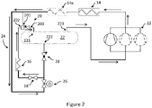
Figure 2 is a schematic diagram of the ejector refrigeration system ofFigure 1 , the ejector refrigeration system being run in a bypass mode of operation. - As seen in
Figure 1 , a refrigeration system includes acompression device 12, a heat rejectingheat exchanger 14, anejector 20, areceiver 22, anexpansion device 18 and a heat absorbingheat exchanger 16 that together form an ejector refrigerant circuit. The ejector refrigerant circuit contains a carbon dioxide based refrigerant fluid (e.g. R744) and circulation of the refrigerant fluid via thecompression device 12 enables the ejector refrigeration system to utilise a refrigeration cycle to satisfy a cooling load. In this example thecompression device 12 is at least onecompressor 12 for compression of the carbon dioxide based refrigerant fluid, the heat rejectingheat exchanger 14 is a gascooler for at least partially condensing the refrigerant fluid, and the heat absorbingheat exchanger 16 is an evaporator for at least partially evaporating the refrigerant fluid. The refrigeration system may advantageously be arranged so that the fluid is fully condensed at thegascooler 14, and fully evaporated at theevaporator 16. - The refrigeration system is configured to provide control and maintenance of temperature conditions of an environment, such as the inside of a freezer cabinet. The ejector refrigerant circuit may be situated outside of the temperature controlled environment. Air passages may be provided to allow air to circulate between the ejector refrigerant circuit and the temperature controlled environment, and the refrigeration system may include fans (not shown) configured to direct ambient air across the
gascooler 14 and air across theevaporator 16 to or from the temperature controlled environment. - The
ejector 20 comprises a primary inlet 201 (e.g. a high-pressure motive inlet), a secondary inlet 202 (e.g. a low-pressure suction inlet) and anoutlet 203. Theejector 20 includes a high-pressure fluid passage extending from theprimary inlet 201 to a high-pressure fluid nozzle; a suction fluid passage extending from thesecondary inlet 202 to a suction chamber surrounding the high-pressure fluid nozzle; a mixing chamber 204 in fluid communication with the high-pressure fluid passage and the suction fluid passage respectively; and a diffusion chamber 205 downstream of the mixing chamber 204. The working principle of theejector 20 is generally described as follows: a high-pressure fluid is converted into a high-momentum fluid when passing through the high-pressure fluid nozzle, the suction fluid is suctioned into the mixing chamber with the high-momentum fluid and mixed with the high-momentum fluid in the mixing chamber, and then diffuses in the diffusion chamber to recover the pressure of the fluid, the fluid then passing through theoutlet 203. - The receiver 22 (e.g. an accumulator) comprises an
inlet 221, aliquid outlet 222 and agas outlet 223.Inlet 221 is connected to theoutlet 203 of theejector 20 and receives refrigerant fluid therefrom, theliquid outlet 222 is connected to the inlet of theexpansion device 18, and thegas outlet 223 is connected to the inlet of thecompressor 12. In many cases it is beneficial to avoid the presence of liquid at the inlet to thecompressor 12. - The refrigeration system includes a
bypass line 24 for use in a bypass mode of operation. The inlet of thebypass line 24 is attached to the ejector refrigerant circuit via the line between the outlet of thegascooler 14 and theprimary inlet 201 of the ejector. The outlet of thebypass line 24 is attached to the ejector refrigerant circuit via the line between theliquid outlet 222 of thereceiver 22 and the inlet of theexpansion valve 18. - The
bypass line 24 includes abypass control valve 26, which is shown as a solenoid valve with an open state and a closed state. Optionally, the ejector refrigerant circuit may include acheck valve 28 on the line between the outlet of thereceiver 22 and the inlet of theexpansion valve 18. In this embodiment, as shown inFigure 1 , the outlet of thebypass line 24 is attached to the ejector refrigerant circuit via the line between the outlet of thecheck valve 28 and the inlet of theexpansion valve 18. - In an alternative embodiment, the
bypass control valve 26 is a three-port valve. The first port of thevalve 26 is connected to the inlet of theexpansion device 18, a second port of thevalve 26 is connected to the outlet of thebypass line 24, and a third port of thevalve 26 is connected to theliquid outlet 222 of thereceiver 22. The use of a three-port valve prevents fluid communication between theliquid outlet 222 of thereceiver 22 and the outlet of thebypass line 24, such that the need for thecheck valve 28 is eliminated. - Optionally, the ejector refrigerant circuit may comprise a plurality of gascoolers, e.g.
first gascooler 14 and second gascooler (heat rejecting heat exchanger) 14a. Thefirst gascooler 14 andsecond gascooler 14a may advantageously be arranged so that the fluid is fully condensed at the outlet of the second gas cooler 14a. - Optionally, the ejector refrigerant circuit may comprise a plurality of evaporators (not shown).
- Optionally, the
compression device 12 may comprise a plurality of compressors in parallel. - Optionally, the
ejector 20 may comprise a plurality of ejectors in parallel. - The refrigeration system may include a controller (not shown) for automatic control of the
bypass control valve 26. The refrigeration system may include various temperature and pressure sensors (not shown) in wired or wireless communication with the controller. - The operation of the refrigeration system is now described with reference to
Figures 1 and2 . - With reference to
Figure 1 , in an ejector mode of operation the carbon dioxide based refrigerant fluid flows through the ejector refrigerant circuit, and does not flow through thebypass line 24. - With reference to
Figure 2 , in a bypass mode of operation the carbon dioxide based refrigerant fluid flows through thebypass line 24, and does not flow through theprimary inlet 201 of theejector 20. When running in a bypass mode of operation the carbon dioxide based refrigerant fluid flows through thecompressor 12, thegascooler 14, theexpansion valve 18 and theevaporator 16 in that order, and accordingly the refrigeration system can be considered to be operating as a typical single-stage vapor-compression refrigeration system. During the bypass mode of operation theejector 20 acts as conduit between thesecondary inlet 202 and theoutlet 203 for the refrigerant fluid flow. Similarly, thereceiver 22 acts as a conduit for between theinlet 221 and thegas outlet 223. - The ejector mode of operation may be initiated automatically, for example upon start-up. Alternatively, on start-up, the controller may be configured to determine whether the refrigeration system should be initiated in the ejector mode of operation or the bypass mode of operation.
- During the operation of the refrigeration system (in either the ejector mode or the bypass mode) the controller may be configured to switch to a different mode of operation in response to received information (e.g. measurements). The controller may receive temperature measurements from sensors, such as a sensor for ambient air temperature (outside air temperature), a sensor for temperature of the temperature controlled environment, and/or sensors within the ejector refrigerant circuit or the bypass line such as for measuring temperatures and/or pressures. The sensors may be comprised as a part of the refrigeration system.
- Alternatively the switching may be performed manually, by a user (e.g. engineer or operator) or performed automatically, for example at certain times of the day.
- Advantageously, in situations when the ambient air temperature (outside air temperature) is high (e.g. during the day and/or during summer), the refrigeration system can switch to be ran in the ejector mode. When the ambient air temperature is high, the fluid leaving the outlet of the gascooler is correspondingly also at a high temperature (and a high pressure). Accordingly, because the pressure of the motive fluid (i.e. the fluid entering the
primary inlet 201 of the ejector 20) is high enough to provide a sufficient pressure lift to the suction fluid (i.e. the fluid entering the secondary inlet 202), the performance advantages of the ejector 20 (such as improved efficiency and/or productivity of the refrigeration system) can be realised. - However, in situations when the ambient air temperature (outside air temperature) is low (e.g. during the night and/or during winter), the fluid leaving the outlet of the gascooler is correspondingly at a low temperature (and a low pressure). As such, because the pressure of the motive fluid is low, the pressure lift provided by the
ejector 20 is low. Theejector 20 thus operates poorly and the performance of the refrigeration system suffers. - Advantageously, the refrigeration system can switch to be ran in the bypass mode if it is determined that the ambient air temperature, or the temperature and/or pressure of the motive fluid (i.e. the fluid leaving the outlet of the gascooler 14) is low, e.g. below a predetermined threshold.
- As discussed above, when operated in the bypass mode, the
bypass valve 26 is opened. Essentially all the fluid flowing from the output of thegascooler 14 thus flows through thebypass line 24, as the high-pressure nozzle of theejector 20 presents a significantly higher pressure barrier for the refrigerant fluid to overcome (as opposed to the expansion valve 18). Thus theejector 20 does not act as an ejector but acts instead as a fluid conduit (e.g. pipe), providing fluid communication between the outlet of theevaporator 16 and theinlet 221 of the receiver. Thus, in accordance with an embodiment of the invention, the refrigeration system is operated as a typical single-stage vapor-compression refrigeration system in conditions where the operation of theejector 20 would be detrimental to the performance of the refrigeration system. - The refrigeration system may not include any components or elements other than those shown in
Figure 1 andFigure 2 , i.e. the refrigeration system may consist of acompression device 12, a heat rejectingheat exchanger 14, anejector 20, areceiver 22, anexpansion device 18, a heat absorbingheat exchanger 16, abypass line 24, abypass control valve 26 and acheck valve 28. Alternatively, the refrigeration system may consist of acompression device 12, a heat rejectingheat exchanger 14, anejector 20, areceiver 22, anexpansion device 18, a heat absorbingheat exchanger 16, abypass line 24 and a three-portbypass control valve 26. - The refrigeration system may also include other more complex additions to the ejector refrigerant circuit or
bypass line 24 such as to adapt the refrigeration system for particular requirements.
Claims (15)
- A refrigeration system for a carbon dioxide based refrigerant fluid, wherein the refrigeration system comprises a refrigerant circuit, the refrigerant circuit comprising a compression device, a heat rejecting heat exchanger, an ejector, a receiver, an expansion device, and a heat absorbing heat exchanger;
wherein the ejector includes a primary inlet, a secondary inlet and an outlet;
wherein the receiver includes an inlet, a liquid outlet and a gas outlet;
wherein the ejector primary inlet is arranged to receive fluid from an outlet of the heat rejecting heat exchanger, the ejector secondary inlet is arranged to receive fluid from an outlet of the heat absorbing heat exchanger, and the ejector outlet is arranged to direct flow to the receiver inlet;
wherein a suction inlet of the compression device is arranged to receive refrigerant fluid from the gas outlet of the receiver; and
wherein the liquid outlet of the receiver is connected via the expansion device to an inlet of the heat absorbing heat exchanger;
characterised in that the refrigeration system comprises a bypass line and a bypass control valve, with the bypass line providing a fluid connection between the outlet of the heat rejecting heat exchanger and the expansion device,
wherein, in an ejector mode of the refrigeration system, the bypass control valve prevents fluid flow through the bypass line such that all fluid exiting the heat rejecting heat exchanger enters the ejector primary inlet; and
wherein, in a bypass mode of the refrigeration system, the bypass control valve permits fluid exiting the heat rejecting heat exchanger to flow through the bypass line to the expansion device and then to the heat absorbing heat exchanger without first passing through the ejector. - A refrigeration system as claimed in claim 1, wherein the bypass line is arranged to provide a direct connection between the outlet of the heat rejecting heat exchanger and an inlet of the expansion device.
- A refrigeration system as claimed in claim 1 or claim 2, wherein the bypass line provides a direct fluid flow path that is only interrupted by the bypass control valve.
- A refrigeration system as claimed in claim 2 or claim 3, wherein the bypass line is arranged such that fluid does not undergo heat exchange with another portion of the refrigeration system when flowing from the outlet of the heat rejecting heat exchanger to the inlet of the expansion device through the bypass line.
- A refrigeration system as claimed in any preceding claim, wherein the refrigeration system includes a check valve between the liquid outlet of the receiver and the expansion device.
- A refrigeration system as claimed in any of claims 1 to 4 wherein the bypass control valve is a three-port valve, a first port of the valve being connected to the expansion device, a second port of the valve being connected to the bypass line, and a third port of the valve being connected to the liquid outlet of the receiver;
wherein, in the ejector mode of the refrigeration system, the bypass control valve allows fluid communication between the first port and the third port; and
wherein, in the bypass mode of the refrigeration system, the bypass control valve allows fluid communication between the first port and the second port. - A refrigeration system as claimed in any preceding claim, wherein the refrigeration system further comprises a controller, the controller being configured to control the bypass control valve.
- A refrigeration system as claimed in claim 7, wherein the refrigeration system comprises a sensor for monitoring an ambient air temperature, and wherein the controller is configured to control the bypass control valve to switch to the bypass mode of the refrigeration system in response to determining that the ambient air temperature is below a predetermined threshold.
- A refrigeration system as claimed in claim 7 or claim 8, wherein the refrigeration system comprises a sensor for monitoring an ambient air temperature, and wherein the controller is configured to control the bypass control valve to switch to the ejector mode of the refrigeration system in response to determining that the ambient air temperature is above a predetermined threshold.
- A refrigeration system as claimed in claim 7, wherein the refrigeration system comprises a refrigerant fluid temperature sensor or refrigerant fluid pressure sensor located between the outlet of the heat rejecting heat exchanger and the ejector primary inlet, and wherein the controller is configured to control the bypass control valve to initiate the bypass mode based on a sensed temperature or a sensed pressure of the refrigerant at the outlet of the heat rejecting heat exchanger.
- A method of controlling a refrigeration system for a carbon dioxide based refrigerant fluid, wherein the refrigeration system comprises:a refrigerant circuit comprising a compression device, a heat rejecting heat exchanger, an ejector, a receiver, an expansion device, and a heat absorbing heat exchanger;wherein the ejector includes a primary inlet, a secondary inlet and an outlet;wherein the receiver includes an inlet, a liquid outlet and a gas outlet;wherein the ejector primary inlet is arranged to receive fluid from an outlet of the heat rejecting heat exchanger, the ejector secondary inlet is arranged to receive fluid from an outlet of the heat absorbing heat exchanger, and the ejector outlet is arranged to direct flow to the receiver inlet;wherein a suction inlet of the compression device is arranged to receive refrigerant fluid from the gas outlet of the receiver; andwherein the liquid outlet of the receiver is connected via the expansion device to an inlet of the heat absorbing heat exchanger;characterised in that the refrigerant circuit comprises a bypass line and a bypass control valve, with the bypass line providing a fluid connection between the outlet of the heat rejecting heat exchanger and the expansion device; the method comprising:running the refrigeration system in either an ejector mode in which all refrigerant fluid exiting the heat rejecting heat exchanger enters the ejector primary inlet, or a bypass mode of the refrigeration system in which refrigerant fluid exiting the heat rejecting heat exchanger is permitted to flow through the bypass line to the expansion device and then to the heat absorbing heat exchanger without first passing through the ejector; andcontrolling the bypass control valve to switch to running the refrigeration system in the other of the ejector mode or the bypass mode.
- A method of controlling a refrigeration system for a carbon dioxide based refrigerant fluid as claimed in claim 11, wherein the bypass control valve is controlled by a controller.
- A method of controlling a refrigeration system for a carbon dioxide based refrigerant fluid as claimed in claim 11 or claim 12, wherein the method comprises:monitoring an ambient air temperature outside of the refrigeration system; andcontrolling the bypass control valve to switch from the ejector mode to the bypass mode in response to determining that the ambient air temperature is below a predetermined threshold.
- A method of controlling a refrigeration system for a carbon dioxide based refrigerant fluid as claimed in claim 11, claim 12 or claim 13, wherein the method comprises:monitoring an ambient air temperature outside of the refrigeration system; andcontrolling the bypass control valve to switch from the bypass mode to the ejector mode in response to determining that the ambient air temperature is above a predetermined threshold.
- A method of controlling a refrigeration system for a carbon dioxide based refrigerant fluid as claimed in claim 11 or claim 12, wherein the method comprises:monitoring a refrigerant fluid temperature or pressure at an outlet of the heat rejecting heat exchanger;controlling the bypass control valve to switch from the ejector mode to the bypass mode in response to determining that the refrigerant fluid temperature or pressure is below a predetermined threshold.
Priority Applications (3)
| Application Number | Priority Date | Filing Date | Title |
|---|---|---|---|
| EP21150423.8A EP4027075B1 (en) | 2021-01-06 | 2021-01-06 | Carbon dioxide refrigeration system with low temperature mode |
| US17/569,130 US11788773B2 (en) | 2021-01-06 | 2022-01-05 | Carbon dioxide refrigeration system with low temperature mode |
| CN202210007862.1A CN114719460A (en) | 2021-01-06 | 2022-01-06 | Carbon dioxide refrigeration system with low temperature mode |
Applications Claiming Priority (1)
| Application Number | Priority Date | Filing Date | Title |
|---|---|---|---|
| EP21150423.8A EP4027075B1 (en) | 2021-01-06 | 2021-01-06 | Carbon dioxide refrigeration system with low temperature mode |
Publications (2)
| Publication Number | Publication Date |
|---|---|
| EP4027075A1 true EP4027075A1 (en) | 2022-07-13 |
| EP4027075B1 EP4027075B1 (en) | 2023-10-11 |
Family
ID=74105849
Family Applications (1)
| Application Number | Title | Priority Date | Filing Date |
|---|---|---|---|
| EP21150423.8A Active EP4027075B1 (en) | 2021-01-06 | 2021-01-06 | Carbon dioxide refrigeration system with low temperature mode |
Country Status (3)
| Country | Link |
|---|---|
| US (1) | US11788773B2 (en) |
| EP (1) | EP4027075B1 (en) |
| CN (1) | CN114719460A (en) |
Families Citing this family (3)
| Publication number | Priority date | Publication date | Assignee | Title |
|---|---|---|---|---|
| AU2020395172B9 (en) * | 2019-12-04 | 2022-07-21 | Bechtel Energy Technologies & Solutions, Inc. | Systems and methods for implementing ejector refrigeration cycles with cascaded evaporation stages |
| US20220307447A1 (en) * | 2021-03-29 | 2022-09-29 | Aurora Flight Sciences Corporation | Charge Air Cooler Bypass Systems and Methods |
| CN119412820B (en) * | 2024-12-25 | 2026-01-27 | 珠海格力电器股份有限公司 | Refrigeration system and data center |
Citations (3)
| Publication number | Priority date | Publication date | Assignee | Title |
|---|---|---|---|---|
| US20040003608A1 (en) * | 2002-07-08 | 2004-01-08 | Hirotsugu Takeuchi | Ejector cycle |
| JP2005076914A (en) * | 2003-08-28 | 2005-03-24 | Tgk Co Ltd | Refrigeration cycle |
| WO2017087794A1 (en) * | 2015-11-20 | 2017-05-26 | Carrier Corporation | Heat pump with ejector |
Family Cites Families (6)
| Publication number | Priority date | Publication date | Assignee | Title |
|---|---|---|---|---|
| JP2001108108A (en) | 1999-10-13 | 2001-04-20 | Matsushita Electric Ind Co Ltd | Sealing material for carbon dioxide refrigerant, compressor and refrigeration system using the same |
| EP2596304A2 (en) * | 2010-07-23 | 2013-05-29 | Carrier Corporation | Ejector cycle refrigerant separator |
| DK2661591T3 (en) * | 2011-01-04 | 2019-02-18 | Carrier Corp | EJEKTOR CYCLE |
| WO2015071967A1 (en) | 2013-11-12 | 2015-05-21 | 三菱電機株式会社 | Refrigeration system |
| US9897363B2 (en) | 2014-11-17 | 2018-02-20 | Heatcraft Refrigeration Products Llc | Transcritical carbon dioxide refrigeration system with multiple ejectors |
| ES2935768T3 (en) * | 2015-05-13 | 2023-03-09 | Carrier Corp | ejector cooling circuit |
-
2021
- 2021-01-06 EP EP21150423.8A patent/EP4027075B1/en active Active
-
2022
- 2022-01-05 US US17/569,130 patent/US11788773B2/en active Active
- 2022-01-06 CN CN202210007862.1A patent/CN114719460A/en active Pending
Patent Citations (3)
| Publication number | Priority date | Publication date | Assignee | Title |
|---|---|---|---|---|
| US20040003608A1 (en) * | 2002-07-08 | 2004-01-08 | Hirotsugu Takeuchi | Ejector cycle |
| JP2005076914A (en) * | 2003-08-28 | 2005-03-24 | Tgk Co Ltd | Refrigeration cycle |
| WO2017087794A1 (en) * | 2015-11-20 | 2017-05-26 | Carrier Corporation | Heat pump with ejector |
Also Published As
| Publication number | Publication date |
|---|---|
| US11788773B2 (en) | 2023-10-17 |
| CN114719460A (en) | 2022-07-08 |
| US20220214079A1 (en) | 2022-07-07 |
| EP4027075B1 (en) | 2023-10-11 |
Similar Documents
| Publication | Publication Date | Title |
|---|---|---|
| US11788773B2 (en) | Carbon dioxide refrigeration system with low temperature mode | |
| EP1757879B1 (en) | Refrigerant cycle apparatus | |
| KR100757592B1 (en) | air-condition heat pump | |
| US20180106514A1 (en) | Refrigerating apparatus | |
| US20100154451A1 (en) | Refrigerating Apparatus | |
| US7752864B2 (en) | Refrigeration apparatus | |
| US8205464B2 (en) | Refrigeration device | |
| CN107003046A (en) | Method for controlling a valve arrangement in a vapor compression system | |
| US20100050672A1 (en) | Refrigeration device | |
| EP2770276A1 (en) | Heat pump | |
| CN114110739B (en) | One-driving-multiple refrigerating and heating air conditioner | |
| CN111919073B (en) | Refrigerating device | |
| EP3098543A1 (en) | A vapour compression system with an ejector and a non-return valve | |
| US20070245768A1 (en) | Refrigeration System | |
| CN114270111B (en) | Heat source unit and refrigeration unit | |
| AU2005252958B2 (en) | Subcooling apparatus | |
| CN110411047B (en) | Refrigerating system | |
| KR100701769B1 (en) | Control method of air conditioner | |
| KR102422010B1 (en) | Multi-air conditioner for heating and cooling operations | |
| CN110573810A (en) | Vapor Compression System with Suction Line Liquid Separator | |
| US20090077985A1 (en) | Refrigerating Apparatus | |
| US11994306B2 (en) | Outdoor unit and air-conditioning apparatus | |
| KR101923770B1 (en) | Engine drive type air conditioner | |
| JP2016205729A (en) | Refrigeration cycle device | |
| CN211854312U (en) | High-efficient evaporation cooling formula cooling water set |
Legal Events
| Date | Code | Title | Description |
|---|---|---|---|
| PUAI | Public reference made under article 153(3) epc to a published international application that has entered the european phase |
Free format text: ORIGINAL CODE: 0009012 |
|
| STAA | Information on the status of an ep patent application or granted ep patent |
Free format text: STATUS: THE APPLICATION HAS BEEN PUBLISHED |
|
| AK | Designated contracting states |
Kind code of ref document: A1 Designated state(s): AL AT BE BG CH CY CZ DE DK EE ES FI FR GB GR HR HU IE IS IT LI LT LU LV MC MK MT NL NO PL PT RO RS SE SI SK SM TR |
|
| STAA | Information on the status of an ep patent application or granted ep patent |
Free format text: STATUS: REQUEST FOR EXAMINATION WAS MADE |
|
| 17P | Request for examination filed |
Effective date: 20221221 |
|
| RBV | Designated contracting states (corrected) |
Designated state(s): AL AT BE BG CH CY CZ DE DK EE ES FI FR GB GR HR HU IE IS IT LI LT LU LV MC MK MT NL NO PL PT RO RS SE SI SK SM TR |
|
| GRAP | Despatch of communication of intention to grant a patent |
Free format text: ORIGINAL CODE: EPIDOSNIGR1 |
|
| STAA | Information on the status of an ep patent application or granted ep patent |
Free format text: STATUS: GRANT OF PATENT IS INTENDED |
|
| INTG | Intention to grant announced |
Effective date: 20230509 |
|
| GRAS | Grant fee paid |
Free format text: ORIGINAL CODE: EPIDOSNIGR3 |
|
| GRAA | (expected) grant |
Free format text: ORIGINAL CODE: 0009210 |
|
| STAA | Information on the status of an ep patent application or granted ep patent |
Free format text: STATUS: THE PATENT HAS BEEN GRANTED |
|
| AK | Designated contracting states |
Kind code of ref document: B1 Designated state(s): AL AT BE BG CH CY CZ DE DK EE ES FI FR GB GR HR HU IE IS IT LI LT LU LV MC MK MT NL NO PL PT RO RS SE SI SK SM TR |
|
| REG | Reference to a national code |
Ref country code: GB Ref legal event code: FG4D |
|
| REG | Reference to a national code |
Ref country code: CH Ref legal event code: EP |
|
| REG | Reference to a national code |
Ref country code: DE Ref legal event code: R096 Ref document number: 602021005689 Country of ref document: DE |
|
| REG | Reference to a national code |
Ref country code: IE Ref legal event code: FG4D |
|
| REG | Reference to a national code |
Ref country code: NL Ref legal event code: FP |
|
| REG | Reference to a national code |
Ref country code: LT Ref legal event code: MG9D |
|
| REG | Reference to a national code |
Ref country code: AT Ref legal event code: MK05 Ref document number: 1620582 Country of ref document: AT Kind code of ref document: T Effective date: 20231011 |
|
| PG25 | Lapsed in a contracting state [announced via postgrant information from national office to epo] |
Ref country code: GR Free format text: LAPSE BECAUSE OF FAILURE TO SUBMIT A TRANSLATION OF THE DESCRIPTION OR TO PAY THE FEE WITHIN THE PRESCRIBED TIME-LIMIT Effective date: 20240112 |
|
| PG25 | Lapsed in a contracting state [announced via postgrant information from national office to epo] |
Ref country code: IS Free format text: LAPSE BECAUSE OF FAILURE TO SUBMIT A TRANSLATION OF THE DESCRIPTION OR TO PAY THE FEE WITHIN THE PRESCRIBED TIME-LIMIT Effective date: 20240211 |
|
| PG25 | Lapsed in a contracting state [announced via postgrant information from national office to epo] |
Ref country code: LT Free format text: LAPSE BECAUSE OF FAILURE TO SUBMIT A TRANSLATION OF THE DESCRIPTION OR TO PAY THE FEE WITHIN THE PRESCRIBED TIME-LIMIT Effective date: 20231011 |
|
| PG25 | Lapsed in a contracting state [announced via postgrant information from national office to epo] |
Ref country code: AT Free format text: LAPSE BECAUSE OF FAILURE TO SUBMIT A TRANSLATION OF THE DESCRIPTION OR TO PAY THE FEE WITHIN THE PRESCRIBED TIME-LIMIT Effective date: 20231011 |
|
| PG25 | Lapsed in a contracting state [announced via postgrant information from national office to epo] |
Ref country code: ES Free format text: LAPSE BECAUSE OF FAILURE TO SUBMIT A TRANSLATION OF THE DESCRIPTION OR TO PAY THE FEE WITHIN THE PRESCRIBED TIME-LIMIT Effective date: 20231011 |
|
| PG25 | Lapsed in a contracting state [announced via postgrant information from national office to epo] |
Ref country code: LT Free format text: LAPSE BECAUSE OF FAILURE TO SUBMIT A TRANSLATION OF THE DESCRIPTION OR TO PAY THE FEE WITHIN THE PRESCRIBED TIME-LIMIT Effective date: 20231011 Ref country code: IS Free format text: LAPSE BECAUSE OF FAILURE TO SUBMIT A TRANSLATION OF THE DESCRIPTION OR TO PAY THE FEE WITHIN THE PRESCRIBED TIME-LIMIT Effective date: 20240211 Ref country code: GR Free format text: LAPSE BECAUSE OF FAILURE TO SUBMIT A TRANSLATION OF THE DESCRIPTION OR TO PAY THE FEE WITHIN THE PRESCRIBED TIME-LIMIT Effective date: 20240112 Ref country code: ES Free format text: LAPSE BECAUSE OF FAILURE TO SUBMIT A TRANSLATION OF THE DESCRIPTION OR TO PAY THE FEE WITHIN THE PRESCRIBED TIME-LIMIT Effective date: 20231011 Ref country code: BG Free format text: LAPSE BECAUSE OF FAILURE TO SUBMIT A TRANSLATION OF THE DESCRIPTION OR TO PAY THE FEE WITHIN THE PRESCRIBED TIME-LIMIT Effective date: 20240111 Ref country code: AT Free format text: LAPSE BECAUSE OF FAILURE TO SUBMIT A TRANSLATION OF THE DESCRIPTION OR TO PAY THE FEE WITHIN THE PRESCRIBED TIME-LIMIT Effective date: 20231011 Ref country code: PT Free format text: LAPSE BECAUSE OF FAILURE TO SUBMIT A TRANSLATION OF THE DESCRIPTION OR TO PAY THE FEE WITHIN THE PRESCRIBED TIME-LIMIT Effective date: 20240212 |
|
| PG25 | Lapsed in a contracting state [announced via postgrant information from national office to epo] |
Ref country code: SE Free format text: LAPSE BECAUSE OF FAILURE TO SUBMIT A TRANSLATION OF THE DESCRIPTION OR TO PAY THE FEE WITHIN THE PRESCRIBED TIME-LIMIT Effective date: 20231011 Ref country code: RS Free format text: LAPSE BECAUSE OF FAILURE TO SUBMIT A TRANSLATION OF THE DESCRIPTION OR TO PAY THE FEE WITHIN THE PRESCRIBED TIME-LIMIT Effective date: 20231011 Ref country code: PL Free format text: LAPSE BECAUSE OF FAILURE TO SUBMIT A TRANSLATION OF THE DESCRIPTION OR TO PAY THE FEE WITHIN THE PRESCRIBED TIME-LIMIT Effective date: 20231011 Ref country code: NO Free format text: LAPSE BECAUSE OF FAILURE TO SUBMIT A TRANSLATION OF THE DESCRIPTION OR TO PAY THE FEE WITHIN THE PRESCRIBED TIME-LIMIT Effective date: 20240111 Ref country code: LV Free format text: LAPSE BECAUSE OF FAILURE TO SUBMIT A TRANSLATION OF THE DESCRIPTION OR TO PAY THE FEE WITHIN THE PRESCRIBED TIME-LIMIT Effective date: 20231011 Ref country code: HR Free format text: LAPSE BECAUSE OF FAILURE TO SUBMIT A TRANSLATION OF THE DESCRIPTION OR TO PAY THE FEE WITHIN THE PRESCRIBED TIME-LIMIT Effective date: 20231011 |
|
| PG25 | Lapsed in a contracting state [announced via postgrant information from national office to epo] |
Ref country code: DK Free format text: LAPSE BECAUSE OF FAILURE TO SUBMIT A TRANSLATION OF THE DESCRIPTION OR TO PAY THE FEE WITHIN THE PRESCRIBED TIME-LIMIT Effective date: 20231011 |
|
| REG | Reference to a national code |
Ref country code: DE Ref legal event code: R097 Ref document number: 602021005689 Country of ref document: DE |
|
| PG25 | Lapsed in a contracting state [announced via postgrant information from national office to epo] |
Ref country code: CZ Free format text: LAPSE BECAUSE OF FAILURE TO SUBMIT A TRANSLATION OF THE DESCRIPTION OR TO PAY THE FEE WITHIN THE PRESCRIBED TIME-LIMIT Effective date: 20231011 |
|
| PG25 | Lapsed in a contracting state [announced via postgrant information from national office to epo] |
Ref country code: SK Free format text: LAPSE BECAUSE OF FAILURE TO SUBMIT A TRANSLATION OF THE DESCRIPTION OR TO PAY THE FEE WITHIN THE PRESCRIBED TIME-LIMIT Effective date: 20231011 |
|
| PG25 | Lapsed in a contracting state [announced via postgrant information from national office to epo] |
Ref country code: SM Free format text: LAPSE BECAUSE OF FAILURE TO SUBMIT A TRANSLATION OF THE DESCRIPTION OR TO PAY THE FEE WITHIN THE PRESCRIBED TIME-LIMIT Effective date: 20231011 Ref country code: SK Free format text: LAPSE BECAUSE OF FAILURE TO SUBMIT A TRANSLATION OF THE DESCRIPTION OR TO PAY THE FEE WITHIN THE PRESCRIBED TIME-LIMIT Effective date: 20231011 Ref country code: RO Free format text: LAPSE BECAUSE OF FAILURE TO SUBMIT A TRANSLATION OF THE DESCRIPTION OR TO PAY THE FEE WITHIN THE PRESCRIBED TIME-LIMIT Effective date: 20231011 Ref country code: EE Free format text: LAPSE BECAUSE OF FAILURE TO SUBMIT A TRANSLATION OF THE DESCRIPTION OR TO PAY THE FEE WITHIN THE PRESCRIBED TIME-LIMIT Effective date: 20231011 Ref country code: DK Free format text: LAPSE BECAUSE OF FAILURE TO SUBMIT A TRANSLATION OF THE DESCRIPTION OR TO PAY THE FEE WITHIN THE PRESCRIBED TIME-LIMIT Effective date: 20231011 Ref country code: CZ Free format text: LAPSE BECAUSE OF FAILURE TO SUBMIT A TRANSLATION OF THE DESCRIPTION OR TO PAY THE FEE WITHIN THE PRESCRIBED TIME-LIMIT Effective date: 20231011 |
|
| PLBE | No opposition filed within time limit |
Free format text: ORIGINAL CODE: 0009261 |
|
| STAA | Information on the status of an ep patent application or granted ep patent |
Free format text: STATUS: NO OPPOSITION FILED WITHIN TIME LIMIT |
|
| PG25 | Lapsed in a contracting state [announced via postgrant information from national office to epo] |
Ref country code: MC Free format text: LAPSE BECAUSE OF FAILURE TO SUBMIT A TRANSLATION OF THE DESCRIPTION OR TO PAY THE FEE WITHIN THE PRESCRIBED TIME-LIMIT Effective date: 20231011 |
|
| PG25 | Lapsed in a contracting state [announced via postgrant information from national office to epo] |
Ref country code: MC Free format text: LAPSE BECAUSE OF FAILURE TO SUBMIT A TRANSLATION OF THE DESCRIPTION OR TO PAY THE FEE WITHIN THE PRESCRIBED TIME-LIMIT Effective date: 20231011 |
|
| REG | Reference to a national code |
Ref country code: CH Ref legal event code: PL |
|
| PG25 | Lapsed in a contracting state [announced via postgrant information from national office to epo] |
Ref country code: LU Free format text: LAPSE BECAUSE OF NON-PAYMENT OF DUE FEES Effective date: 20240106 |
|
| 26N | No opposition filed |
Effective date: 20240712 |
|
| PG25 | Lapsed in a contracting state [announced via postgrant information from national office to epo] |
Ref country code: LU Free format text: LAPSE BECAUSE OF NON-PAYMENT OF DUE FEES Effective date: 20240106 |
|
| PG25 | Lapsed in a contracting state [announced via postgrant information from national office to epo] |
Ref country code: BE Free format text: LAPSE BECAUSE OF NON-PAYMENT OF DUE FEES Effective date: 20240131 |
|
| PG25 | Lapsed in a contracting state [announced via postgrant information from national office to epo] |
Ref country code: CH Free format text: LAPSE BECAUSE OF NON-PAYMENT OF DUE FEES Effective date: 20240131 |
|
| PG25 | Lapsed in a contracting state [announced via postgrant information from national office to epo] |
Ref country code: SI Free format text: LAPSE BECAUSE OF FAILURE TO SUBMIT A TRANSLATION OF THE DESCRIPTION OR TO PAY THE FEE WITHIN THE PRESCRIBED TIME-LIMIT Effective date: 20231011 |
|
| PG25 | Lapsed in a contracting state [announced via postgrant information from national office to epo] |
Ref country code: SI Free format text: LAPSE BECAUSE OF FAILURE TO SUBMIT A TRANSLATION OF THE DESCRIPTION OR TO PAY THE FEE WITHIN THE PRESCRIBED TIME-LIMIT Effective date: 20231011 Ref country code: CH Free format text: LAPSE BECAUSE OF NON-PAYMENT OF DUE FEES Effective date: 20240131 Ref country code: BE Free format text: LAPSE BECAUSE OF NON-PAYMENT OF DUE FEES Effective date: 20240131 |
|
| REG | Reference to a national code |
Ref country code: BE Ref legal event code: MM Effective date: 20240131 |
|
| PG25 | Lapsed in a contracting state [announced via postgrant information from national office to epo] |
Ref country code: IE Free format text: LAPSE BECAUSE OF NON-PAYMENT OF DUE FEES Effective date: 20240106 |
|
| PG25 | Lapsed in a contracting state [announced via postgrant information from national office to epo] |
Ref country code: IE Free format text: LAPSE BECAUSE OF NON-PAYMENT OF DUE FEES Effective date: 20240106 |
|
| PG25 | Lapsed in a contracting state [announced via postgrant information from national office to epo] |
Ref country code: CY Free format text: LAPSE BECAUSE OF FAILURE TO SUBMIT A TRANSLATION OF THE DESCRIPTION OR TO PAY THE FEE WITHIN THE PRESCRIBED TIME-LIMIT; INVALID AB INITIO Effective date: 20210106 |
|
| PG25 | Lapsed in a contracting state [announced via postgrant information from national office to epo] |
Ref country code: HU Free format text: LAPSE BECAUSE OF FAILURE TO SUBMIT A TRANSLATION OF THE DESCRIPTION OR TO PAY THE FEE WITHIN THE PRESCRIBED TIME-LIMIT; INVALID AB INITIO Effective date: 20210106 |
|
| GBPC | Gb: european patent ceased through non-payment of renewal fee |
Effective date: 20250106 |
|
| PG25 | Lapsed in a contracting state [announced via postgrant information from national office to epo] |
Ref country code: FI Free format text: LAPSE BECAUSE OF FAILURE TO SUBMIT A TRANSLATION OF THE DESCRIPTION OR TO PAY THE FEE WITHIN THE PRESCRIBED TIME-LIMIT Effective date: 20231011 |
|
| PG25 | Lapsed in a contracting state [announced via postgrant information from national office to epo] |
Ref country code: GB Free format text: LAPSE BECAUSE OF NON-PAYMENT OF DUE FEES Effective date: 20250106 |
|
| PG25 | Lapsed in a contracting state [announced via postgrant information from national office to epo] |
Ref country code: TR Free format text: LAPSE BECAUSE OF FAILURE TO SUBMIT A TRANSLATION OF THE DESCRIPTION OR TO PAY THE FEE WITHIN THE PRESCRIBED TIME-LIMIT Effective date: 20231011 |
|
| PGFP | Annual fee paid to national office [announced via postgrant information from national office to epo] |
Ref country code: NL Payment date: 20251217 Year of fee payment: 6 Ref country code: FR Payment date: 20251217 Year of fee payment: 6 |
|
| PGFP | Annual fee paid to national office [announced via postgrant information from national office to epo] |
Ref country code: DE Payment date: 20251217 Year of fee payment: 6 |
|
| PGFP | Annual fee paid to national office [announced via postgrant information from national office to epo] |
Ref country code: IT Payment date: 20260107 Year of fee payment: 6 |