EP4027022A1 - Air cylinder, head cover, and rod cover - Google Patents
Air cylinder, head cover, and rod cover Download PDFInfo
- Publication number
- EP4027022A1 EP4027022A1 EP20860012.2A EP20860012A EP4027022A1 EP 4027022 A1 EP4027022 A1 EP 4027022A1 EP 20860012 A EP20860012 A EP 20860012A EP 4027022 A1 EP4027022 A1 EP 4027022A1
- Authority
- EP
- European Patent Office
- Prior art keywords
- flow rate
- flow path
- air
- check valve
- pilot
- Prior art date
- Legal status (The legal status is an assumption and is not a legal conclusion. Google has not performed a legal analysis and makes no representation as to the accuracy of the status listed.)
- Granted
Links
Images





Classifications
-
- F—MECHANICAL ENGINEERING; LIGHTING; HEATING; WEAPONS; BLASTING
- F15—FLUID-PRESSURE ACTUATORS; HYDRAULICS OR PNEUMATICS IN GENERAL
- F15B—SYSTEMS ACTING BY MEANS OF FLUIDS IN GENERAL; FLUID-PRESSURE ACTUATORS, e.g. SERVOMOTORS; DETAILS OF FLUID-PRESSURE SYSTEMS, NOT OTHERWISE PROVIDED FOR
- F15B15/00—Fluid-actuated devices for displacing a member from one position to another; Gearing associated therewith
- F15B15/08—Characterised by the construction of the motor unit
- F15B15/14—Characterised by the construction of the motor unit of the straight-cylinder type
- F15B15/1423—Component parts; Constructional details
- F15B15/1433—End caps
-
- F—MECHANICAL ENGINEERING; LIGHTING; HEATING; WEAPONS; BLASTING
- F15—FLUID-PRESSURE ACTUATORS; HYDRAULICS OR PNEUMATICS IN GENERAL
- F15B—SYSTEMS ACTING BY MEANS OF FLUIDS IN GENERAL; FLUID-PRESSURE ACTUATORS, e.g. SERVOMOTORS; DETAILS OF FLUID-PRESSURE SYSTEMS, NOT OTHERWISE PROVIDED FOR
- F15B11/00—Servomotor systems without provision for follow-up action; Circuits therefor
- F15B11/02—Systems essentially incorporating special features for controlling the speed or actuating force of an output member
- F15B11/04—Systems essentially incorporating special features for controlling the speed or actuating force of an output member for controlling the speed
- F15B11/0413—Systems essentially incorporating special features for controlling the speed or actuating force of an output member for controlling the speed in one direction only, with no control in the reverse direction, e.g. check valve in parallel with a throttle valve
-
- F—MECHANICAL ENGINEERING; LIGHTING; HEATING; WEAPONS; BLASTING
- F15—FLUID-PRESSURE ACTUATORS; HYDRAULICS OR PNEUMATICS IN GENERAL
- F15B—SYSTEMS ACTING BY MEANS OF FLUIDS IN GENERAL; FLUID-PRESSURE ACTUATORS, e.g. SERVOMOTORS; DETAILS OF FLUID-PRESSURE SYSTEMS, NOT OTHERWISE PROVIDED FOR
- F15B13/00—Details of servomotor systems ; Valves for servomotor systems
- F15B13/02—Fluid distribution or supply devices characterised by their adaptation to the control of servomotors
- F15B13/027—Check valves
-
- F—MECHANICAL ENGINEERING; LIGHTING; HEATING; WEAPONS; BLASTING
- F15—FLUID-PRESSURE ACTUATORS; HYDRAULICS OR PNEUMATICS IN GENERAL
- F15B—SYSTEMS ACTING BY MEANS OF FLUIDS IN GENERAL; FLUID-PRESSURE ACTUATORS, e.g. SERVOMOTORS; DETAILS OF FLUID-PRESSURE SYSTEMS, NOT OTHERWISE PROVIDED FOR
- F15B15/00—Fluid-actuated devices for displacing a member from one position to another; Gearing associated therewith
- F15B15/08—Characterised by the construction of the motor unit
- F15B15/14—Characterised by the construction of the motor unit of the straight-cylinder type
-
- F—MECHANICAL ENGINEERING; LIGHTING; HEATING; WEAPONS; BLASTING
- F15—FLUID-PRESSURE ACTUATORS; HYDRAULICS OR PNEUMATICS IN GENERAL
- F15B—SYSTEMS ACTING BY MEANS OF FLUIDS IN GENERAL; FLUID-PRESSURE ACTUATORS, e.g. SERVOMOTORS; DETAILS OF FLUID-PRESSURE SYSTEMS, NOT OTHERWISE PROVIDED FOR
- F15B15/00—Fluid-actuated devices for displacing a member from one position to another; Gearing associated therewith
- F15B15/18—Combined units comprising both motor and pump
-
- F—MECHANICAL ENGINEERING; LIGHTING; HEATING; WEAPONS; BLASTING
- F15—FLUID-PRESSURE ACTUATORS; HYDRAULICS OR PNEUMATICS IN GENERAL
- F15B—SYSTEMS ACTING BY MEANS OF FLUIDS IN GENERAL; FLUID-PRESSURE ACTUATORS, e.g. SERVOMOTORS; DETAILS OF FLUID-PRESSURE SYSTEMS, NOT OTHERWISE PROVIDED FOR
- F15B15/00—Fluid-actuated devices for displacing a member from one position to another; Gearing associated therewith
- F15B15/20—Other details, e.g. assembly with regulating devices
- F15B15/204—Control means for piston speed or actuating force without external control, e.g. control valve inside the piston
-
- F—MECHANICAL ENGINEERING; LIGHTING; HEATING; WEAPONS; BLASTING
- F15—FLUID-PRESSURE ACTUATORS; HYDRAULICS OR PNEUMATICS IN GENERAL
- F15B—SYSTEMS ACTING BY MEANS OF FLUIDS IN GENERAL; FLUID-PRESSURE ACTUATORS, e.g. SERVOMOTORS; DETAILS OF FLUID-PRESSURE SYSTEMS, NOT OTHERWISE PROVIDED FOR
- F15B15/00—Fluid-actuated devices for displacing a member from one position to another; Gearing associated therewith
- F15B15/20—Other details, e.g. assembly with regulating devices
- F15B15/22—Other details, e.g. assembly with regulating devices for accelerating or decelerating the stroke
-
- F—MECHANICAL ENGINEERING; LIGHTING; HEATING; WEAPONS; BLASTING
- F15—FLUID-PRESSURE ACTUATORS; HYDRAULICS OR PNEUMATICS IN GENERAL
- F15B—SYSTEMS ACTING BY MEANS OF FLUIDS IN GENERAL; FLUID-PRESSURE ACTUATORS, e.g. SERVOMOTORS; DETAILS OF FLUID-PRESSURE SYSTEMS, NOT OTHERWISE PROVIDED FOR
- F15B11/00—Servomotor systems without provision for follow-up action; Circuits therefor
- F15B11/06—Servomotor systems without provision for follow-up action; Circuits therefor involving features specific to the use of a compressible medium, e.g. air, steam
-
- F—MECHANICAL ENGINEERING; LIGHTING; HEATING; WEAPONS; BLASTING
- F15—FLUID-PRESSURE ACTUATORS; HYDRAULICS OR PNEUMATICS IN GENERAL
- F15B—SYSTEMS ACTING BY MEANS OF FLUIDS IN GENERAL; FLUID-PRESSURE ACTUATORS, e.g. SERVOMOTORS; DETAILS OF FLUID-PRESSURE SYSTEMS, NOT OTHERWISE PROVIDED FOR
- F15B21/00—Common features of fluid actuator systems; Fluid-pressure actuator systems or details thereof, not covered by any other group of this subclass
- F15B21/10—Delay devices or arrangements
-
- F—MECHANICAL ENGINEERING; LIGHTING; HEATING; WEAPONS; BLASTING
- F15—FLUID-PRESSURE ACTUATORS; HYDRAULICS OR PNEUMATICS IN GENERAL
- F15B—SYSTEMS ACTING BY MEANS OF FLUIDS IN GENERAL; FLUID-PRESSURE ACTUATORS, e.g. SERVOMOTORS; DETAILS OF FLUID-PRESSURE SYSTEMS, NOT OTHERWISE PROVIDED FOR
- F15B2211/00—Circuits for servomotor systems
- F15B2211/30—Directional control
- F15B2211/305—Directional control characterised by the type of valves
- F15B2211/30505—Non-return valves, i.e. check valves
-
- F—MECHANICAL ENGINEERING; LIGHTING; HEATING; WEAPONS; BLASTING
- F15—FLUID-PRESSURE ACTUATORS; HYDRAULICS OR PNEUMATICS IN GENERAL
- F15B—SYSTEMS ACTING BY MEANS OF FLUIDS IN GENERAL; FLUID-PRESSURE ACTUATORS, e.g. SERVOMOTORS; DETAILS OF FLUID-PRESSURE SYSTEMS, NOT OTHERWISE PROVIDED FOR
- F15B2211/00—Circuits for servomotor systems
- F15B2211/30—Directional control
- F15B2211/32—Directional control characterised by the type of actuation
- F15B2211/329—Directional control characterised by the type of actuation actuated by fluid pressure
-
- F—MECHANICAL ENGINEERING; LIGHTING; HEATING; WEAPONS; BLASTING
- F15—FLUID-PRESSURE ACTUATORS; HYDRAULICS OR PNEUMATICS IN GENERAL
- F15B—SYSTEMS ACTING BY MEANS OF FLUIDS IN GENERAL; FLUID-PRESSURE ACTUATORS, e.g. SERVOMOTORS; DETAILS OF FLUID-PRESSURE SYSTEMS, NOT OTHERWISE PROVIDED FOR
- F15B2211/00—Circuits for servomotor systems
- F15B2211/30—Directional control
- F15B2211/355—Pilot pressure control
-
- F—MECHANICAL ENGINEERING; LIGHTING; HEATING; WEAPONS; BLASTING
- F15—FLUID-PRESSURE ACTUATORS; HYDRAULICS OR PNEUMATICS IN GENERAL
- F15B—SYSTEMS ACTING BY MEANS OF FLUIDS IN GENERAL; FLUID-PRESSURE ACTUATORS, e.g. SERVOMOTORS; DETAILS OF FLUID-PRESSURE SYSTEMS, NOT OTHERWISE PROVIDED FOR
- F15B2211/00—Circuits for servomotor systems
- F15B2211/40—Flow control
- F15B2211/405—Flow control characterised by the type of flow control means or valve
- F15B2211/40515—Flow control characterised by the type of flow control means or valve with variable throttles or orifices
-
- F—MECHANICAL ENGINEERING; LIGHTING; HEATING; WEAPONS; BLASTING
- F15—FLUID-PRESSURE ACTUATORS; HYDRAULICS OR PNEUMATICS IN GENERAL
- F15B—SYSTEMS ACTING BY MEANS OF FLUIDS IN GENERAL; FLUID-PRESSURE ACTUATORS, e.g. SERVOMOTORS; DETAILS OF FLUID-PRESSURE SYSTEMS, NOT OTHERWISE PROVIDED FOR
- F15B2211/00—Circuits for servomotor systems
- F15B2211/40—Flow control
- F15B2211/405—Flow control characterised by the type of flow control means or valve
- F15B2211/40576—Assemblies of multiple valves
- F15B2211/40584—Assemblies of multiple valves the flow control means arranged in parallel with a check valve
-
- F—MECHANICAL ENGINEERING; LIGHTING; HEATING; WEAPONS; BLASTING
- F15—FLUID-PRESSURE ACTUATORS; HYDRAULICS OR PNEUMATICS IN GENERAL
- F15B—SYSTEMS ACTING BY MEANS OF FLUIDS IN GENERAL; FLUID-PRESSURE ACTUATORS, e.g. SERVOMOTORS; DETAILS OF FLUID-PRESSURE SYSTEMS, NOT OTHERWISE PROVIDED FOR
- F15B2211/00—Circuits for servomotor systems
- F15B2211/40—Flow control
- F15B2211/405—Flow control characterised by the type of flow control means or valve
- F15B2211/40576—Assemblies of multiple valves
- F15B2211/40592—Assemblies of multiple valves with multiple valves in parallel flow paths
-
- F—MECHANICAL ENGINEERING; LIGHTING; HEATING; WEAPONS; BLASTING
- F15—FLUID-PRESSURE ACTUATORS; HYDRAULICS OR PNEUMATICS IN GENERAL
- F15B—SYSTEMS ACTING BY MEANS OF FLUIDS IN GENERAL; FLUID-PRESSURE ACTUATORS, e.g. SERVOMOTORS; DETAILS OF FLUID-PRESSURE SYSTEMS, NOT OTHERWISE PROVIDED FOR
- F15B2211/00—Circuits for servomotor systems
- F15B2211/40—Flow control
- F15B2211/415—Flow control characterised by the connections of the flow control means in the circuit
- F15B2211/41527—Flow control characterised by the connections of the flow control means in the circuit being connected to an output member and a directional control valve
-
- F—MECHANICAL ENGINEERING; LIGHTING; HEATING; WEAPONS; BLASTING
- F15—FLUID-PRESSURE ACTUATORS; HYDRAULICS OR PNEUMATICS IN GENERAL
- F15B—SYSTEMS ACTING BY MEANS OF FLUIDS IN GENERAL; FLUID-PRESSURE ACTUATORS, e.g. SERVOMOTORS; DETAILS OF FLUID-PRESSURE SYSTEMS, NOT OTHERWISE PROVIDED FOR
- F15B2211/00—Circuits for servomotor systems
- F15B2211/60—Circuit components or control therefor
- F15B2211/635—Circuits providing pilot pressure to pilot pressure-controlled fluid circuit elements
- F15B2211/6355—Circuits providing pilot pressure to pilot pressure-controlled fluid circuit elements having valve means
-
- F—MECHANICAL ENGINEERING; LIGHTING; HEATING; WEAPONS; BLASTING
- F15—FLUID-PRESSURE ACTUATORS; HYDRAULICS OR PNEUMATICS IN GENERAL
- F15B—SYSTEMS ACTING BY MEANS OF FLUIDS IN GENERAL; FLUID-PRESSURE ACTUATORS, e.g. SERVOMOTORS; DETAILS OF FLUID-PRESSURE SYSTEMS, NOT OTHERWISE PROVIDED FOR
- F15B2211/00—Circuits for servomotor systems
- F15B2211/60—Circuit components or control therefor
- F15B2211/67—Methods for controlling pilot pressure
-
- F—MECHANICAL ENGINEERING; LIGHTING; HEATING; WEAPONS; BLASTING
- F15—FLUID-PRESSURE ACTUATORS; HYDRAULICS OR PNEUMATICS IN GENERAL
- F15B—SYSTEMS ACTING BY MEANS OF FLUIDS IN GENERAL; FLUID-PRESSURE ACTUATORS, e.g. SERVOMOTORS; DETAILS OF FLUID-PRESSURE SYSTEMS, NOT OTHERWISE PROVIDED FOR
- F15B2211/00—Circuits for servomotor systems
- F15B2211/70—Output members, e.g. hydraulic motors or cylinders or control therefor
- F15B2211/705—Output members, e.g. hydraulic motors or cylinders or control therefor characterised by the type of output members or actuators
- F15B2211/7051—Linear output members
- F15B2211/7053—Double-acting output members
-
- F—MECHANICAL ENGINEERING; LIGHTING; HEATING; WEAPONS; BLASTING
- F15—FLUID-PRESSURE ACTUATORS; HYDRAULICS OR PNEUMATICS IN GENERAL
- F15B—SYSTEMS ACTING BY MEANS OF FLUIDS IN GENERAL; FLUID-PRESSURE ACTUATORS, e.g. SERVOMOTORS; DETAILS OF FLUID-PRESSURE SYSTEMS, NOT OTHERWISE PROVIDED FOR
- F15B2211/00—Circuits for servomotor systems
- F15B2211/70—Output members, e.g. hydraulic motors or cylinders or control therefor
- F15B2211/75—Control of speed of the output member
-
- F—MECHANICAL ENGINEERING; LIGHTING; HEATING; WEAPONS; BLASTING
- F15—FLUID-PRESSURE ACTUATORS; HYDRAULICS OR PNEUMATICS IN GENERAL
- F15B—SYSTEMS ACTING BY MEANS OF FLUIDS IN GENERAL; FLUID-PRESSURE ACTUATORS, e.g. SERVOMOTORS; DETAILS OF FLUID-PRESSURE SYSTEMS, NOT OTHERWISE PROVIDED FOR
- F15B2211/00—Circuits for servomotor systems
- F15B2211/80—Other types of control related to particular problems or conditions
- F15B2211/885—Control specific to the type of fluid, e.g. specific to magnetorheological fluid
- F15B2211/8855—Compressible fluids, e.g. specific to pneumatics
Definitions
- the present invention relates to an air cylinder, a head cover, and a rod cover.
- a shock absorbing mechanism has been used in which a cushioning material made of a soft resin such as rubber or urethane or the like, or an oil damper or the like is attached to an end part of an air cylinder, to thereby cushion an impact at a stroke end.
- a shock absorbing mechanism that mechanically mitigates shocks in the cylinder is limited in terms of the number of operations it can perform, and requires regular maintenance.
- a speed controller (flow rate controller) in which, by throttling the exhaust air that is discharged from the air cylinder in the vicinity of a stroke end, an operating speed of the air cylinder is reduced.
- Such a conventional flow rate controller is an external component that is connected to ports of the air cylinder, which increases the number of component parts of the drive device of the air cylinder, and the device configuration of the drive device becomes complex. Further, the structure thereof is complicated, and a problem arises in that, when attempting to form the head cover and the rod cover integrally with the air cylinder, machining becomes difficult, and productivity is reduced.
- the present invention has the object of providing an air cylinder, a head cover, and a rod cover, which enable the device configuration of a drive device to be simplified, and which are superior in terms of productivity.
- One aspect of the present invention is an air cylinder, comprising a cylinder tube in which a cylinder chamber is formed, a head cover configured to close one end of the cylinder tube, a rod cover configured to close another end of the cylinder tube, a piston configured to slide in the cylinder chamber, a piston rod having one end connected to the piston, a port provided in each of the head cover and the rod cover, and a flow rate controller incorporated into at least one of the head cover or the rod cover, wherein the flow rate controller includes a first flow path configured to allow communication between the port and the cylinder chamber, a first flow rate adjustment part disposed in the first flow path, a second flow path disposed in parallel with the first flow path, a second flow rate adjustment part disposed in the second flow path, a pilot check valve disposed in series with the second flow rate adjustment part in the second flow path, and a third flow rate adjustment part configured to supply and discharge pilot air to and from the pilot check valve, and wherein, depending on a pressure of the pilot air, the pilot check valve switches between
- FIG. 1 Another aspect of the present invention is a head cover for an air cylinder that covers a head side end part of a cylinder tube, the head cover comprising, a port, a first flow path configured to communicate with the port and a cylinder chamber of the air cylinder, a first flow rate adjustment part disposed in the first flow path, a second flow path disposed in parallel with the first flow path, a second flow rate adjustment part disposed in the second flow path, a pilot check valve disposed in the second flow path, and connected in series with the second flow rate adjustment part, and a third flow rate adjustment part configured to supply and discharge pilot air to and from the pilot check valve, wherein, depending on a pressure of the pilot air, the pilot check valve switches between a state allowing passage of exhaust air discharged from the cylinder chamber, and a state preventing the passage of the exhaust air.
- FIG. 1 Another further aspect of the present invention is a rod cover for an air cylinder that covers a rod side end part of a cylinder tube, the rod cover comprising, a port, a first flow path configured to communicate with the port and a cylinder chamber of the air cylinder, a first flow rate adjustment part disposed in the first flow path, a second flow path disposed in parallel with the first flow path, a second flow rate adjustment part disposed in the second flow path, a pilot check valve disposed in the second flow path, and connected in series with the second flow rate adjustment part, and a third flow rate adjustment part configured to supply and discharge pilot air to and from the pilot check valve, wherein, depending on a pressure of the pilot air, the pilot check valve switches between a state allowing passage of exhaust air discharged from the cylinder chamber, and a state preventing the passage of the exhaust air.
- the device configuration of the drive device can be simplified, and because the structure thereof is simplified, productivity is superior.
- an air cylinder 10 is a double acting cylinder that is used in an automated equipment line or the like.
- the air cylinder 10 is equipped with a cylindrical cylinder tube 12, a head cover 14 that seals a head side end part of the cylinder tube 12, and a rod cover 16 that seals a rod side end part of the cylinder tube 12.
- the cylinder tube 12, the head cover 14, and the rod cover 16 are connected in an axial direction by a plurality of connecting rods 22.
- a piston 18 that partitions a cylinder chamber 12c, and a piston rod 20 connected to the piston 18.
- a head side flow rate controller 24 is connected to a head side pressure chamber 12a of the piston 18, and a rod side flow rate controller 24A is connected to a rod side pressure chamber 12b of the piston 18.
- the flow rate controller 24 is incorporated into the head cover 14, and is connected to a head side port 14a.
- the flow rate controller 24A is incorporated into the rod cover 16, and is connected to a rod side port 16a.
- the head side flow rate controller 24 includes a first flow path 26 connecting the head side port 14a and the cylinder chamber 12c, and a second flow path 30 disposed in parallel with the first flow path 26.
- a first flow rate adjustment part 28 is provided in the first flow path 26.
- the first flow rate adjustment part 28 is made up of a throttle valve that variably throttles the flow rate of air passing through the first flow path 26, and by primarily throttling the flow rate of exhaust air, suppresses an operating speed of the piston 18 in the vicinity of the stroke end.
- a second flow rate adjustment part 32, and a pilot check valve 38 are provided in the second flow path 30.
- the second flow rate adjustment part 32 is a throttle valve, and can variably adjust the flow rate of air passing through the second flow path 30.
- the pilot check valve 38 is a check valve through which the passage of exhaust air is switched depending on the pressure of the pilot air, and includes an inlet 38a, an outlet 38b, and a pilot port 38c.
- the inlet 38a is connected to the head side port 14a side of the second flow path 30, and the outlet 38b is connected to the cylinder chamber 12c side of the second flow path 30.
- the pilot check valve 38 When the pressure of the pilot air falls below a predetermined value, the pilot check valve 38 operates as a check valve that allows air to pass from the inlet 38a toward the outlet 38b, while preventing the passage of air in the opposite direction. Further, when the pressure of the pilot air becomes greater than or equal to the predetermined value, the pilot check valve 38 allows the air to pass in both directions from the inlet 38a toward the outlet 38b, and vice versa.
- the flow rate controller 24 further includes a third flow path 34 connecting the head side port 14a and the cylinder chamber 12c, and a pilot air flow path 40 connecting the head side port 14a and the pilot port 38c of the pilot check valve 38.
- a check valve 36 is disposed in the third flow path 34.
- the check valve 36 is connected in a direction that allows passage of air flowing from the head side port 14a toward the cylinder chamber 12c, while preventing the passage of air in the opposite direction.
- the third flow path 34 and the check valve 36 allow high pressure air to pass freely toward the cylinder chamber 12c.
- the third flow path 34 and the check valve 36 need not necessarily be provided independently as shown in the drawings, but may be an integrated member with the throttle valve of the first flow rate adjustment part 28 or the throttle valve of the second flow rate adjustment part 32, in the form of a check valve equipped throttle valve.
- a third flow rate adjustment part 42 which is capable of variably adjusting the flow rate of the pilot air supplied to and discharged from the pilot check valve 38, is provided in the pilot air flow path 40.
- the third flow rate adjustment part 42 includes a throttle valve 42a, and a check valve 42b which is connected in parallel with the throttle valve 42a.
- the check valve 42b is connected in a direction that allows air to pass from the head side port 14a toward the pilot check valve 38, while preventing the passage of air in the opposite direction, and quickly supplies the pilot air to the pilot check valve 38.
- the throttle valve 42a is capable of variably adjusting the flow rate of the pilot air discharged through the pilot air flow path 40, and determines a timing at which the operation of the pilot check valve 38 is switched.
- the third flow rate adjustment part 42 can be configured in the form of a check valve equipped throttle valve in which the throttle valve 42a and the check valve 42b are integrated.
- the head side flow rate controller 24 is configured in the manner described above.
- the rod side flow rate controller 24A is configured in substantially the same manner as the head side flow rate controller 24, constituent elements thereof which are the same as those of the head side flow rate controller 24 are designated by the same reference numerals, and detailed description thereof is omitted.
- the constituent elements of the rod side flow rate controller 24A are indicated by appending the letter "A" at the end of each of the reference numerals, in order to distinguish them from the constituent elements of the head side flow rate controller 24.
- the rod cover 16 includes a main body portion 60A formed in the shape of a flat rectangular parallelepiped.
- An insertion member 61 through which the piston rod 20 is inserted is provided at a central part of an outer end surface 60a of the main body portion 60A, and connecting holes 22a for fixing the connecting rods 22 are provided at the four corners of the outer end surface 60a of the main body portion 60A.
- the connecting holes 22a extend in the axial direction of the piston rod 20 and penetrate through the main body portion 60A.
- the throttle valves which constitute a first flow rate adjustment part 28A, a second flow rate adjustment part 32A, and a third flow rate adjustment part 42A, are provided together with the rod side port 16a on an upper surface 60b of the rod cover 16.
- an annular shaped cylinder tube mounting groove 64 in which the cylinder tube 12 is mounted is provided on an inner end surface 60c of the main body portion 60A of the rod cover 16, and an inner side of the cylinder tube mounting groove 64 faces an inner side of the rod side pressure chamber 12b.
- An insertion hole 20a through which the piston rod 20 is inserted is formed in a central portion of the cylinder tube mounting groove 64, and a first flow path 26A and valve holes 59a and 59b open circumferentially around the piston rod 20.
- a check valve 36A is mounted in the valve hole 59a, and a pilot check valve 38A is mounted in the valve hole 59b.
- the first flow rate adjustment part 28A and the second flow rate adjustment part 32A are arranged on the cylinder tube 12 side of the rod side port 16a, and the third flow rate adjustment part 42A is arranged on the lateral side of the rod side port 16a. Further, the pilot check valve 38A is disposed in the interior of the main body portion 60A between the rod side port 16a and the third flow rate adjustment part 42A.
- the first flow path 26A opens on a side portion of the rod side port 16a, and extends toward an inlet 28a of the first flow rate adjustment part 28A.
- the first flow rate adjustment part 28A is a throttle valve provided in a valve hole 59c, and includes a needle 82 that variably closes a flow path between the inlet 28a that opens on a side portion of the valve hole 59c and an outlet 28b that opens on a bottom portion of the valve hole 59c.
- the needle 82 is fixed in the valve hole 59c by a screw mechanism, and when the needle 82 is rotated and the needle 82 is made to project toward the outlet 28b, the flow path is narrowed. A portion of the first flow path 26A on the outlet side extends toward and opens on the inner end surface 60c.
- the second flow path 30A is connected via the second flow rate adjustment part 32A to an inlet 38a of the pilot check valve 38A.
- the second flow rate adjustment part 32A includes a valve main body 94 provided in a valve hole 59d that opens on the upper surface 60b and communicates with the second flow path 30A.
- the valve main body 94 is mounted in the valve hole 59d by a screw mechanism 94a, and by rotating the valve main body 94, the valve main body 94 is made to project toward the second flow path 30A, or alternatively, the valve main body 94 is made to retract away from the second flow path 30A, whereby the flow rate of the second flow path 30A can be variably adjusted.
- the third flow path 34A opens on a lower end of the rod side port 16a, extends toward the inner end surface 60c of the main body portion 60A, and is connected to the check valve 36A.
- the check valve 36A is inserted into the valve hole 59a that opens on the inner end surface 60c, and includes a valve element 90, a supporting body 86 that is fitted into the valve hole 59a and thereby supports the valve element 90, and a spring 88 connecting the valve element 90 and the supporting body 86.
- An inlet 90a having a reduced diameter is formed on a rear side of the valve hole 59a, and the valve element 90 is arranged so as to close the inlet 90a.
- the spring 88 is arranged between the valve element 90 and the supporting body 86, and biases the valve element 90 toward the inlet 90a side.
- the air flowing from the inlet 90a side flows into the valve hole 59a by pressing the valve element 90 toward the supporting body 86 side against the biasing force of the spring 88, and flows via an opening 86a into the rod side pressure chamber 12b.
- the check valve 36A prevents the exhaust air of the rod side pressure chamber 12b from passing.
- the pilot air flow path 40A extends from the rod side port 16a toward an inlet 43a of the third flow rate adjustment part 42A, and is connected via the third flow rate adjustment part 42A to the pilot port 38c.
- the third flow rate adjustment part 42A is disposed in a valve hole 59e that opens on the upper surface 60b and communicates with the pilot air flow path 40A.
- the third flow rate adjustment part 42A is a check valve equipped throttle valve, and includes a flow path member 95a constituting an inner side flow path and an outer side flow path, a needle 95b capable of variably adjusting the cross-sectional area of the inner side flow path, and a seal member 95c provided in the outer side flow path.
- the seal member 95c is an elastic member having a substantially V-shaped cross section with a concave portion directed toward an outlet 43b, and prevents the passage of air flowing in a reverse direction from the outlet 43b toward the inlet 43a in the outer side flow path.
- the pilot check valve 38A communicates with the pilot port 38c of the pilot check valve 38A.
- the pilot check valve 38A is provided in the valve hole 59b that is formed by penetrating through the main body portion 60A in the axial direction and has a circular cross section.
- the valve hole 59b includes a piston chamber 65 formed on the outer end surface 60a side, a check valve accommodating portion 67 formed on the inner end surface 60c side, and an intermediate portion 66 formed between the piston chamber 65 and the check valve accommodating portion 67.
- An end part of the piston chamber 65 on the outer end surface 60a side is sealed by a cap 80.
- the pilot air flow path 40A opens as the pilot port 38c in the piston chamber 65 in the vicinity of the cap 80.
- An air vent hole 62 opens in the vicinity of an end part of the piston chamber 65 on the inner end surface 60c side.
- the air vent hole 62 opens on the upper surface 60b of the main body portion 60A.
- the intermediate portion 66 is formed with an inner diameter that is smaller than that of the piston chamber 65 and the check valve accommodating portion 67, and includes, at a boundary portion between the intermediate portion 66 and the check valve accommodating portion 67, a reduced diameter portion 66a formed by reducing the diameter of the intermediate portion 66.
- a pilot piston 76 is arranged in the piston chamber 65 and the intermediate portion 66.
- the pilot piston 76 includes a piston member 76a that slides inside the piston chamber 65.
- the piston member 76a partitions the piston chamber 65 into a portion communicating with the pilot air flow path 40A and a portion communicating with the air vent hole 62, and receives the pressure of the pilot air from the pilot air flow path 40A to generate a driving force in a rightward direction as shown in the drawing.
- the pilot piston 76 projects toward the inner end surface 60c side as shown in FIG. 6 .
- a guide member 76b is formed to project from the piston member 76a toward the intermediate portion 66 side.
- the guide member 76b is formed with a diameter that is slightly smaller than the inner diameter of the intermediate portion 66, and slides along the intermediate portion 66.
- a packing 76d in order to prevent leakage of air is provided on an outer circumferential part of the guide member 76b.
- a rod member 76c extends from an end part of the guide member 76b on the check valve accommodating portion 67 side.
- the rod member 76c is formed with a diameter that is smaller than that of the reduced diameter portion 66a of the intermediate portion 66, and is separated from the inner circumferential surfaces of the intermediate portion 66 and the reduced diameter portion 66a.
- a valve element 70, a supporting body 72 that supports the valve element 70, and a return spring 74 that biases the valve element 70 are provided in the check valve accommodating portion 67.
- the supporting body 72 is fitted into an end part of the check valve accommodating portion 67 on the inner end surface 60c side.
- a cylindrical shaft hole 72a is provided in a central portion of the supporting body 72, and a shaft portion 70a of the valve element 70 is inserted into the shaft hole 72a.
- an opening 72b is provided on an outer circumferential portion of the supporting body 72, and an inner side of the check valve accommodating portion 67 and the rod side pressure chamber 12b are capable of communicating through the opening 72b.
- the valve element 70 includes a closing portion 70b which is a portion thereof that faces the reduced diameter portion 66a and is enlarged in diameter in a disk-like shape, and the shaft portion 70a extends from the closing portion 70b toward the supporting body 72 side.
- the closing portion 70b is biased by the return spring 74 toward the reduced diameter portion 66a side, and the closing portion 70b covers and closes the reduced diameter portion 66a.
- the pilot piston 76 of the pilot check valve 38A is biased toward the cap 80 side by the elastic force of the return spring 74.
- the valve element 70 is separated away from the reduced diameter portion 66a and then allows passage of the air flowing toward the rod side pressure chamber 12b through the second flow path 30A.
- the closing portion 70b is biased toward the reduced diameter portion 66a side, and therefore, the valve element 70 prevents the exhaust air from passing.
- the pilot piston 76 when the pressure of the pilot air is greater than or equal to the predetermined value, the pilot piston 76 is displaced toward the check valve accommodating portion 67 side. In such a state, by the rod member 76c of the pilot piston 76 projecting toward the check valve accommodating portion 67 side, the closing portion 70b of the valve element 70 is retained in a state of being separated away from the reduced diameter portion 66a. Therefore, the pilot check valve 38A allows the air to pass not only in a direction from the inlet 38a toward the outlet 38b, but also in a direction opposite thereto.
- the rod cover 16 is configured in the manner described above, and hereinafter, a description will be given concerning the head cover 14.
- the head cover 14 is equipped with a rectangular parallelepiped shaped main body portion 60 that is flat in the axial direction.
- the connecting holes 22a open on an outer end surface 60a of the main body portion 60.
- the head side port 14a, the first flow rate adjustment part 28, the second flow rate adjustment part 32, and the third flow rate adjustment part 42 are exposed on an upper surface 60b of the main body portion 60, and an air vent hole 62 opens thereon.
- a cylinder tube mounting groove 64 is formed on an inner end surface 60c of the main body portion 60, and openings of the check valve 36, the pilot check valve 38, and the first flow path 26 are provided on the inner side thereof.
- the pilot check valve 38 is disposed closer to the center of the main body portion 60 than the head cover 14, and the third flow rate adjustment part 42 is arranged in an overlapping manner with the upper surface 60b side of the pilot check valve 38. Consequently, the pathway of the pilot air flow path 40 is made simpler in structure.
- the cross-sectional shapes along the line XB-XB of the first flow path 26, the third flow path 34, the first flow rate adjustment part 28, and the check valve 36 are the same as the cross-sectional shapes of the first flow path 26A, the third flow path 34A, the first flow rate adjustment part 28A, and the check valve 36A of the rod cover 16 shown in FIG. 7 .
- the cross-sectional shapes along the line XA-XA of FIG. 11 of the second flow path 30 and the second flow rate adjustment part 32 are the same as the cross sectional shapes shown in FIG. 9 .
- the layout of the head cover 14 differs from the layout of the rod cover 16 in that the pilot air flow path 40 opens on the upper end of the piston chamber 65, and the second flow path 30 opens on the upper end of the intermediate portion 66,.
- the other structural features of the pilot check valve 38 that is formed in the head cover 14 are the same as those of the pilot check valve 38A shown in FIG. 5 , and since the same structural elements thereof are designated by the same reference numerals, detailed description of such features is omitted herein.
- the air cylinder 10, the head cover 14, and the rod cover 16 according to the present embodiment are configured in the manner described above. Hereinafter, a description will be given concerning operations and actions thereof.
- a drive device 50 is connected thereto, which includes a high pressure air supply source 52, exhaust ports 54, and an operation switching valve 56 that connects the high pressure air supply source 52 and the exhaust port 54 to the head side port 14a and the rod side port 16a in a switchable manner.
- the operation switching valve 56 is a 5-port valve that is switched electrically, and includes first through fifth ports 56a to 56e.
- the first port 56a is connected to the head side port 14a
- the second port 56b is connected to the rod side port 16a.
- the third port 56c and the fifth port 56e are connected to the exhaust ports 54
- the fourth port 56d is connected to the high pressure air supply source 52.
- the operation switching valve 56 by placing the first port 56a and the fourth port 56d in communication with each other, and placing the second port 56b and the fifth port 56e in communication with each other, the high pressure air supply source 52 is connected to the head side port 14a, the exhaust port 54 is connected to the rod side port 16a, and the piston 18 performs an operating stroke.
- the high pressure air from the high pressure air supply source 52 flows from the head side port 14a to the head side flow rate controller 24.
- the high pressure air flows to the head side pressure chamber 12a through the first flow path 26, the second flow path 30, and the third flow path 34.
- the high pressure air is supplied to the head side pressure chamber 12a in a free flowing manner through the third flow path 34 and the check valve 36, without passing through the throttle valve.
- pilot air is supplied from the pilot port 38c of the pilot check valve 38 through the pilot air flow path 40 and the check valve 42b of the third flow rate adjustment part 42. Consequently, as shown in FIG. 6 , in the pilot check valve 38 on the head side, the rod member 76c of the pilot piston 76 projects toward the check valve accommodating portion 67 side, and allows flow in both directions.
- the exhaust air from the rod side pressure chamber 12b is discharged through the rod side flow rate controller 24A. Since the check valve 36A does not allow the exhaust air to pass, as shown by the arrow B1, the exhaust air is discharged through the first flow path 26A, and as shown by the arrow B2, the exhaust air is discharged through the second flow path 30A. Until the middle of the operating stroke, the pilot check valve 38A of the second flow path 30A maintains the pressure of the pilot air that was accumulated in the piston chamber 65 in the previous return stroke. Therefore, as shown in FIG.
- the pilot check valve 38A allows the exhaust air to pass. Therefore, in FIG. 2 , as shown by the arrow B1 + B2, the exhaust air is discharged at a predetermined flow rate (first control flow) through the first flow path 26A and the second flow path 30A.
- the operating speed of the piston 18 is limited due to the flow rate of the exhaust air.
- the pilot air of the pilot check valve 38A gradually flows out through the pilot air flow path 40A and the third flow rate adjustment part 42A.
- the pressure of the pilot air in the pilot check valve 38A gradually decreases.
- the pilot piston 76 of the pilot check valve 38A returns to the initial position as shown in FIG. 5 , and the reduced diameter portion 66a is closed by the valve element 70. Consequently, as shown by the arrow B1 in FIG. 13 , the exhaust air is switched to a second control flow of flowing through the first flow path 26A.
- the second control flow since the flow rate of the exhaust air is further throttled by the first flow rate adjustment part 28A than in the first control flow, the operating speed of the piston 18 is restricted. Consequently, an impact at the stroke end of the piston 18 can be suppressed.
- the operation switching valve 56 is switched from the first position to the second position, whereby the high pressure air supply source 52 is connected to the rod side port 16a, the exhaust port 54 is connected to the head side port 14a, and a return stroke is initiated.
- the operations in the return stroke simply involve a switching of places in the operating stroke between the head side flow rate controller 24 and the rod side flow rate controller 24A, and since the operations in the return stroke and the operations in the operating stroke are substantially the same, a description of such operations will be omitted.
- the air cylinder 10, the head cover 14, and the rod cover 16 of the present embodiment realize the following advantageous effects.
- the air cylinder 10 is equipped with the cylinder tube 12 in which the cylinder chamber 12c is formed, the head cover 14 that closes one end of the cylinder tube 12, the rod cover 16 that closes the other end of the cylinder tube 12, the piston 18 that slides in the cylinder chamber 12c, the piston rod 20 having one end connected to the piston 18, the ports 14a and 16a provided respectively in the head cover 14 and the rod cover 16, and the flow rate controller 24 incorporated into at least one of the head cover 14 or the rod cover 16, wherein the flow rate controller 24 includes the first flow paths 26 and 26A that allow communication between the ports 14a and 16a and the cylinder chamber 12c, the first flow rate adjustment parts 28 and 28A disposed in the first flow paths 26 and 26A, the second flow paths 30 and 30A disposed in parallel with the first flow paths 26 and 26A, the second flow rate adjustment parts 32 and 32A disposed in the second flow paths 30 and 30A, the pilot check valves 38 and 38A disposed in series with the second flow rate adjustment parts 32 and 32A in the second flow
- pilot check valves 38 and 38A which are of a simple structure, are used in order to switch the control flow of the exhaust air, a switching valve in which a shuttle valve or a three-way valve is used becomes unnecessary, and the internal structure is simplified. Further, since constituent members, for which precision is required, such as sleeves and spools that constitute a shuttle valve or a three-way valve are rendered unnecessary, grinding or polishing and surface treatment requiring a number of production steps are rendered unnecessary, and manufacturing can be carried out at a low cost.
- the above-described air cylinder 10 may further comprise the check valves 36 and 36A that are disposed in parallel with the first flow rate adjustment parts 28 and 28A, and allow passage of air flowing from the ports 14a and 16a toward the cylinder chamber 12c.
- the high pressure air can be supplied to the cylinder chamber 12c in a free flowing manner, and the air cylinder 10 can be operated at high speed.
- the third flow rate adjustment parts 42 and 42A may be equipped with the throttle valve 42a, and the check valve 42b that is disposed in parallel with the throttle valve 42a and allows passage of air flowing toward the pilot port 38c.
- the head cover 14 is the head cover 14 for the air cylinder 10 that covers a head side end part of the cylinder tube 12, the head cover comprising the head side port 14a, the first flow path 26 that communicates with the head side port 14a and the cylinder chamber 12c of the air cylinder 10, the first flow rate adjustment part 28 disposed in the first flow path 26, the second flow path 30 disposed in parallel with the first flow path 26, the second flow rate adjustment part 32 disposed in the second flow path 30, the pilot check valve 38 disposed in the second flow path 30, and connected in series with the second flow rate adjustment part 32, and the third flow rate adjustment part 42 that supplies and discharges the pilot air to and from the pilot check valve 38, wherein, depending on the pressure of the pilot air, the pilot check valve 38 switches between a state allowing passage of the exhaust air discharged from the cylinder chamber 12c, and a state preventing the passage of the exhaust air.
- the rod cover 16 is the rod cover 16 for the air cylinder 10 that covers a rod side end part of the cylinder tube 12, the rod cover comprising the rod side port 16a, the first flow path 26A that communicates with the rod side port 16a and the cylinder chamber 12c of the air cylinder 10, the first flow rate adjustment part 28A disposed in the first flow path 26A, the second flow path 30A disposed in parallel with the first flow path 26A, the second flow rate adjustment part 32A disposed in the second flow path 30A, the pilot check valve 38A disposed in the second flow path 30A, and connected in series with the second flow rate adjustment part 32A, and the third flow rate adjustment part 42A that supplies and discharges the pilot air to and from the pilot check valve 38A, wherein, depending on the pressure of the pilot air, the pilot check valve 38A switches between a state allowing passage of the exhaust air discharged from the cylinder chamber 12c, and a state preventing the passage of the exhaust air.
- pilot check valves 38 and 38A which are of a simple structure, are used in order to switch the control flow of the exhaust air, a switching valve in which a shuttle valve or a three-way valve is used becomes unnecessary, the internal structure is simplified, and manufacturing can be carried out at a low cost.
Landscapes
- Engineering & Computer Science (AREA)
- Physics & Mathematics (AREA)
- Fluid Mechanics (AREA)
- Mechanical Engineering (AREA)
- General Engineering & Computer Science (AREA)
- Fluid-Pressure Circuits (AREA)
- Actuator (AREA)
Abstract
Description
- The present invention relates to an air cylinder, a head cover, and a rod cover.
- Conventionally, a shock absorbing mechanism has been used in which a cushioning material made of a soft resin such as rubber or urethane or the like, or an oil damper or the like is attached to an end part of an air cylinder, to thereby cushion an impact at a stroke end. However, such a shock absorbing mechanism that mechanically mitigates shocks in the cylinder is limited in terms of the number of operations it can perform, and requires regular maintenance.
- In order to resolve such incompatibility, in
JP 5578502 B2 - However, such a conventional flow rate controller is an external component that is connected to ports of the air cylinder, which increases the number of component parts of the drive device of the air cylinder, and the device configuration of the drive device becomes complex. Further, the structure thereof is complicated, and a problem arises in that, when attempting to form the head cover and the rod cover integrally with the air cylinder, machining becomes difficult, and productivity is reduced.
- The present invention has the object of providing an air cylinder, a head cover, and a rod cover, which enable the device configuration of a drive device to be simplified, and which are superior in terms of productivity.
- One aspect of the present invention is an air cylinder, comprising a cylinder tube in which a cylinder chamber is formed, a head cover configured to close one end of the cylinder tube, a rod cover configured to close another end of the cylinder tube, a piston configured to slide in the cylinder chamber, a piston rod having one end connected to the piston, a port provided in each of the head cover and the rod cover, and a flow rate controller incorporated into at least one of the head cover or the rod cover, wherein the flow rate controller includes a first flow path configured to allow communication between the port and the cylinder chamber, a first flow rate adjustment part disposed in the first flow path, a second flow path disposed in parallel with the first flow path, a second flow rate adjustment part disposed in the second flow path, a pilot check valve disposed in series with the second flow rate adjustment part in the second flow path, and a third flow rate adjustment part configured to supply and discharge pilot air to and from the pilot check valve, and wherein, depending on a pressure of the pilot air, the pilot check valve switches between a state allowing passage of exhaust air discharged from the cylinder chamber, and a state preventing the passage of the exhaust air.
- Another aspect of the present invention is a head cover for an air cylinder that covers a head side end part of a cylinder tube, the head cover comprising, a port, a first flow path configured to communicate with the port and a cylinder chamber of the air cylinder, a first flow rate adjustment part disposed in the first flow path, a second flow path disposed in parallel with the first flow path, a second flow rate adjustment part disposed in the second flow path, a pilot check valve disposed in the second flow path, and connected in series with the second flow rate adjustment part, and a third flow rate adjustment part configured to supply and discharge pilot air to and from the pilot check valve, wherein, depending on a pressure of the pilot air, the pilot check valve switches between a state allowing passage of exhaust air discharged from the cylinder chamber, and a state preventing the passage of the exhaust air.
- Another further aspect of the present invention is a rod cover for an air cylinder that covers a rod side end part of a cylinder tube, the rod cover comprising, a port, a first flow path configured to communicate with the port and a cylinder chamber of the air cylinder, a first flow rate adjustment part disposed in the first flow path, a second flow path disposed in parallel with the first flow path, a second flow rate adjustment part disposed in the second flow path, a pilot check valve disposed in the second flow path, and connected in series with the second flow rate adjustment part, and a third flow rate adjustment part configured to supply and discharge pilot air to and from the pilot check valve, wherein, depending on a pressure of the pilot air, the pilot check valve switches between a state allowing passage of exhaust air discharged from the cylinder chamber, and a state preventing the passage of the exhaust air.
- In accordance with the air cylinder, the head cover, and the rod cover according to the above-described aspects, the device configuration of the drive device can be simplified, and because the structure thereof is simplified, productivity is superior.
-
-
FIG. 1 is a perspective view of an air cylinder according to an embodiment of the present invention; -
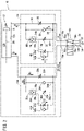
FIG. 2 is a fluid circuit diagram of the air cylinder shown inFIG. 1 , and a drive device thereof; -
FIG. 3A is a perspective view of a rod cover shown inFIG. 1 ; -
FIG. 3B is a side view of a cylinder tube side of the rod cover shown inFIG. 3A ; -
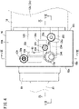
FIG. 4 is a plan view of the rod cover shown inFIG. 3A ; -
FIG. 5 is a cross-sectional view taken along line V-V ofFIG. 3B ; -
FIG. 6 is a cross-sectional view taken along line VI-VI ofFIG. 3B , showing a state in which a pilot check valve shown inFIG. 5 is opened by a pilot pressure; -
FIG. 7 is a cross-sectional view taken along line VII-VII ofFIG. 4 ; -
FIG. 8 is a cross-sectional view taken along line VIII-VIII ofFIG. 4 ; -
FIG. 9 is a cross-sectional view taken along line IX-IX ofFIG. 4 ; -
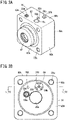
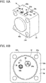
FIG. 10A is a perspective view of a head cover shown inFIG. 1 ; -
FIG. 10B is a side view of a cylinder tube side of the head cover shown inFIG. 10A ; -
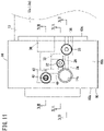
FIG. 11 is a plan view of the head cover shown inFIG. 10A ; -
FIG. 12 is a cross-sectional view taken along line XII-XII ofFIG. 11 ; and -
FIG. 13 is a fluid circuit diagram showing an operation in the vicinity of a stroke end of the air cylinder shown inFIG. 1 . - Hereinafter, a preferred embodiment of the present invention will be presented and described in detail below with reference to the accompanying drawings.
- As shown in
FIG. 1 , anair cylinder 10 is a double acting cylinder that is used in an automated equipment line or the like. Theair cylinder 10 is equipped with acylindrical cylinder tube 12, ahead cover 14 that seals a head side end part of thecylinder tube 12, and arod cover 16 that seals a rod side end part of thecylinder tube 12. Thecylinder tube 12, thehead cover 14, and therod cover 16 are connected in an axial direction by a plurality of connectingrods 22. - As shown in
FIG. 2 , in the interior of thecylinder tube 12, there are provided apiston 18 that partitions acylinder chamber 12c, and apiston rod 20 connected to thepiston 18. A head sideflow rate controller 24 is connected to a headside pressure chamber 12a of thepiston 18, and a rod sideflow rate controller 24A is connected to a rodside pressure chamber 12b of thepiston 18. Theflow rate controller 24 is incorporated into thehead cover 14, and is connected to ahead side port 14a. Theflow rate controller 24A is incorporated into therod cover 16, and is connected to arod side port 16a. - The head side
flow rate controller 24 includes afirst flow path 26 connecting thehead side port 14a and thecylinder chamber 12c, and asecond flow path 30 disposed in parallel with thefirst flow path 26. A first flowrate adjustment part 28 is provided in thefirst flow path 26. The first flowrate adjustment part 28 is made up of a throttle valve that variably throttles the flow rate of air passing through thefirst flow path 26, and by primarily throttling the flow rate of exhaust air, suppresses an operating speed of thepiston 18 in the vicinity of the stroke end. - A second flow
rate adjustment part 32, and apilot check valve 38 are provided in thesecond flow path 30. The second flowrate adjustment part 32 is a throttle valve, and can variably adjust the flow rate of air passing through thesecond flow path 30. Thepilot check valve 38 is a check valve through which the passage of exhaust air is switched depending on the pressure of the pilot air, and includes aninlet 38a, anoutlet 38b, and apilot port 38c. Theinlet 38a is connected to thehead side port 14a side of thesecond flow path 30, and theoutlet 38b is connected to thecylinder chamber 12c side of thesecond flow path 30. When the pressure of the pilot air falls below a predetermined value, thepilot check valve 38 operates as a check valve that allows air to pass from theinlet 38a toward theoutlet 38b, while preventing the passage of air in the opposite direction. Further, when the pressure of the pilot air becomes greater than or equal to the predetermined value, thepilot check valve 38 allows the air to pass in both directions from theinlet 38a toward theoutlet 38b, and vice versa. - The
flow rate controller 24 further includes athird flow path 34 connecting thehead side port 14a and thecylinder chamber 12c, and a pilotair flow path 40 connecting thehead side port 14a and thepilot port 38c of thepilot check valve 38. Acheck valve 36 is disposed in thethird flow path 34. Thecheck valve 36 is connected in a direction that allows passage of air flowing from thehead side port 14a toward thecylinder chamber 12c, while preventing the passage of air in the opposite direction. Thethird flow path 34 and thecheck valve 36 allow high pressure air to pass freely toward thecylinder chamber 12c. Thethird flow path 34 and thecheck valve 36 need not necessarily be provided independently as shown in the drawings, but may be an integrated member with the throttle valve of the first flowrate adjustment part 28 or the throttle valve of the second flowrate adjustment part 32, in the form of a check valve equipped throttle valve. - A third flow
rate adjustment part 42, which is capable of variably adjusting the flow rate of the pilot air supplied to and discharged from thepilot check valve 38, is provided in the pilotair flow path 40. The third flowrate adjustment part 42 includes athrottle valve 42a, and acheck valve 42b which is connected in parallel with thethrottle valve 42a. Thecheck valve 42b is connected in a direction that allows air to pass from thehead side port 14a toward thepilot check valve 38, while preventing the passage of air in the opposite direction, and quickly supplies the pilot air to thepilot check valve 38. Thethrottle valve 42a is capable of variably adjusting the flow rate of the pilot air discharged through the pilotair flow path 40, and determines a timing at which the operation of thepilot check valve 38 is switched. The third flowrate adjustment part 42 can be configured in the form of a check valve equipped throttle valve in which thethrottle valve 42a and thecheck valve 42b are integrated. - The head side
flow rate controller 24 is configured in the manner described above. On the other hand, since the rod sideflow rate controller 24A is configured in substantially the same manner as the head sideflow rate controller 24, constituent elements thereof which are the same as those of the head sideflow rate controller 24 are designated by the same reference numerals, and detailed description thereof is omitted. However, the constituent elements of the rod sideflow rate controller 24A are indicated by appending the letter "A" at the end of each of the reference numerals, in order to distinguish them from the constituent elements of the head sideflow rate controller 24. - Hereinafter, a description will be given concerning a specific configuration of the
head cover 14 and therod cover 16 in which theflow rate controllers - As shown in
FIG. 3A , therod cover 16 includes amain body portion 60A formed in the shape of a flat rectangular parallelepiped. Aninsertion member 61 through which thepiston rod 20 is inserted is provided at a central part of anouter end surface 60a of themain body portion 60A, and connectingholes 22a for fixing the connectingrods 22 are provided at the four corners of theouter end surface 60a of themain body portion 60A. The connectingholes 22a extend in the axial direction of thepiston rod 20 and penetrate through themain body portion 60A. The throttle valves, which constitute a first flowrate adjustment part 28A, a second flowrate adjustment part 32A, and a third flowrate adjustment part 42A, are provided together with therod side port 16a on anupper surface 60b of therod cover 16. - As shown in
FIG. 3B , an annular shaped cylindertube mounting groove 64 in which thecylinder tube 12 is mounted is provided on aninner end surface 60c of themain body portion 60A of therod cover 16, and an inner side of the cylindertube mounting groove 64 faces an inner side of the rodside pressure chamber 12b. Aninsertion hole 20a through which thepiston rod 20 is inserted is formed in a central portion of the cylindertube mounting groove 64, and afirst flow path 26A andvalve holes piston rod 20. Acheck valve 36A is mounted in thevalve hole 59a, and apilot check valve 38A is mounted in thevalve hole 59b. - As shown in
FIG. 4 , the first flowrate adjustment part 28A and the second flowrate adjustment part 32A are arranged on thecylinder tube 12 side of therod side port 16a, and the third flowrate adjustment part 42A is arranged on the lateral side of therod side port 16a. Further, thepilot check valve 38A is disposed in the interior of themain body portion 60A between therod side port 16a and the third flowrate adjustment part 42A. - Ends of the
first flow path 26A, asecond flow path 30A, athird flow path 34A, and a pilotair flow path 40A open, respectively, at therod side port 16a. As shown inFIG. 7 , thefirst flow path 26A opens on a side portion of therod side port 16a, and extends toward aninlet 28a of the first flowrate adjustment part 28A. The first flowrate adjustment part 28A is a throttle valve provided in avalve hole 59c, and includes aneedle 82 that variably closes a flow path between theinlet 28a that opens on a side portion of thevalve hole 59c and anoutlet 28b that opens on a bottom portion of thevalve hole 59c. Theneedle 82 is fixed in thevalve hole 59c by a screw mechanism, and when theneedle 82 is rotated and theneedle 82 is made to project toward theoutlet 28b, the flow path is narrowed. A portion of thefirst flow path 26A on the outlet side extends toward and opens on theinner end surface 60c. - As shown in
FIG. 6 , thesecond flow path 30A is connected via the second flowrate adjustment part 32A to aninlet 38a of thepilot check valve 38A. As shown inFIG. 9 , the second flowrate adjustment part 32A includes a valvemain body 94 provided in avalve hole 59d that opens on theupper surface 60b and communicates with thesecond flow path 30A. The valvemain body 94 is mounted in thevalve hole 59d by ascrew mechanism 94a, and by rotating the valvemain body 94, the valvemain body 94 is made to project toward thesecond flow path 30A, or alternatively, the valvemain body 94 is made to retract away from thesecond flow path 30A, whereby the flow rate of thesecond flow path 30A can be variably adjusted. - As shown in
FIGS. 7 and8 , thethird flow path 34A opens on a lower end of therod side port 16a, extends toward theinner end surface 60c of themain body portion 60A, and is connected to thecheck valve 36A. Thecheck valve 36A is inserted into thevalve hole 59a that opens on theinner end surface 60c, and includes avalve element 90, a supportingbody 86 that is fitted into thevalve hole 59a and thereby supports thevalve element 90, and aspring 88 connecting thevalve element 90 and the supportingbody 86. Aninlet 90a having a reduced diameter is formed on a rear side of thevalve hole 59a, and thevalve element 90 is arranged so as to close theinlet 90a. Thespring 88 is arranged between thevalve element 90 and the supportingbody 86, and biases thevalve element 90 toward theinlet 90a side. The air flowing from theinlet 90a side flows into thevalve hole 59a by pressing thevalve element 90 toward the supportingbody 86 side against the biasing force of thespring 88, and flows via anopening 86a into the rodside pressure chamber 12b. In the case that the pressure on the side of the rodside pressure chamber 12b is high, since thevalve element 90 is pressed against theinlet 90a, thecheck valve 36A prevents the exhaust air of the rodside pressure chamber 12b from passing. - As shown in
FIG. 8 , the pilotair flow path 40A extends from therod side port 16a toward aninlet 43a of the third flowrate adjustment part 42A, and is connected via the third flowrate adjustment part 42A to thepilot port 38c. The third flowrate adjustment part 42A is disposed in avalve hole 59e that opens on theupper surface 60b and communicates with the pilotair flow path 40A. The third flowrate adjustment part 42A is a check valve equipped throttle valve, and includes aflow path member 95a constituting an inner side flow path and an outer side flow path, aneedle 95b capable of variably adjusting the cross-sectional area of the inner side flow path, and aseal member 95c provided in the outer side flow path. Theseal member 95c is an elastic member having a substantially V-shaped cross section with a concave portion directed toward anoutlet 43b, and prevents the passage of air flowing in a reverse direction from theoutlet 43b toward theinlet 43a in the outer side flow path. - As shown in
FIG. 5 , one end of the pilotair flow path 40A communicates with thepilot port 38c of thepilot check valve 38A. Thepilot check valve 38A is provided in thevalve hole 59b that is formed by penetrating through themain body portion 60A in the axial direction and has a circular cross section. Thevalve hole 59b includes apiston chamber 65 formed on theouter end surface 60a side, a checkvalve accommodating portion 67 formed on theinner end surface 60c side, and anintermediate portion 66 formed between thepiston chamber 65 and the checkvalve accommodating portion 67. An end part of thepiston chamber 65 on theouter end surface 60a side is sealed by acap 80. The pilotair flow path 40A opens as thepilot port 38c in thepiston chamber 65 in the vicinity of thecap 80. Anair vent hole 62 opens in the vicinity of an end part of thepiston chamber 65 on theinner end surface 60c side. Theair vent hole 62 opens on theupper surface 60b of themain body portion 60A. - The
intermediate portion 66 is formed with an inner diameter that is smaller than that of thepiston chamber 65 and the checkvalve accommodating portion 67, and includes, at a boundary portion between theintermediate portion 66 and the checkvalve accommodating portion 67, a reduceddiameter portion 66a formed by reducing the diameter of theintermediate portion 66. Apilot piston 76 is arranged in thepiston chamber 65 and theintermediate portion 66. Thepilot piston 76 includes apiston member 76a that slides inside thepiston chamber 65. Thepiston member 76a partitions thepiston chamber 65 into a portion communicating with the pilotair flow path 40A and a portion communicating with theair vent hole 62, and receives the pressure of the pilot air from the pilotair flow path 40A to generate a driving force in a rightward direction as shown in the drawing. When the pressure of the pilot air increases, thepilot piston 76 projects toward theinner end surface 60c side as shown inFIG. 6 . - As shown in
FIG. 5 , aguide member 76b is formed to project from thepiston member 76a toward theintermediate portion 66 side. Theguide member 76b is formed with a diameter that is slightly smaller than the inner diameter of theintermediate portion 66, and slides along theintermediate portion 66. A packing 76d in order to prevent leakage of air is provided on an outer circumferential part of theguide member 76b. Arod member 76c extends from an end part of theguide member 76b on the checkvalve accommodating portion 67 side. Therod member 76c is formed with a diameter that is smaller than that of the reduceddiameter portion 66a of theintermediate portion 66, and is separated from the inner circumferential surfaces of theintermediate portion 66 and the reduceddiameter portion 66a. - A
valve element 70, a supportingbody 72 that supports thevalve element 70, and areturn spring 74 that biases thevalve element 70 are provided in the checkvalve accommodating portion 67. The supportingbody 72 is fitted into an end part of the checkvalve accommodating portion 67 on theinner end surface 60c side. Acylindrical shaft hole 72a is provided in a central portion of the supportingbody 72, and ashaft portion 70a of thevalve element 70 is inserted into theshaft hole 72a. Further, anopening 72b is provided on an outer circumferential portion of the supportingbody 72, and an inner side of the checkvalve accommodating portion 67 and the rodside pressure chamber 12b are capable of communicating through theopening 72b. Thevalve element 70 includes aclosing portion 70b which is a portion thereof that faces the reduceddiameter portion 66a and is enlarged in diameter in a disk-like shape, and theshaft portion 70a extends from the closingportion 70b toward the supportingbody 72 side. The closingportion 70b is biased by thereturn spring 74 toward the reduceddiameter portion 66a side, and theclosing portion 70b covers and closes the reduceddiameter portion 66a. - In a state in which the pressure of the pilot air is not acting, as shown in the drawing, the
pilot piston 76 of thepilot check valve 38A is biased toward thecap 80 side by the elastic force of thereturn spring 74. In such a state, when the high pressure air flows in from theintermediate portion 66, since the closingportion 70b is pressed by the high pressure air, thevalve element 70 is separated away from the reduceddiameter portion 66a and then allows passage of the air flowing toward the rodside pressure chamber 12b through thesecond flow path 30A. On the other hand, when the pressure of the exhaust air in the rodside pressure chamber 12b increases, the closingportion 70b is biased toward the reduceddiameter portion 66a side, and therefore, thevalve element 70 prevents the exhaust air from passing. - Further, as shown in
FIG. 6 , when the pressure of the pilot air is greater than or equal to the predetermined value, thepilot piston 76 is displaced toward the checkvalve accommodating portion 67 side. In such a state, by therod member 76c of thepilot piston 76 projecting toward the checkvalve accommodating portion 67 side, the closingportion 70b of thevalve element 70 is retained in a state of being separated away from the reduceddiameter portion 66a. Therefore, thepilot check valve 38A allows the air to pass not only in a direction from theinlet 38a toward theoutlet 38b, but also in a direction opposite thereto. - The
rod cover 16 is configured in the manner described above, and hereinafter, a description will be given concerning thehead cover 14. As shown inFIG. 10A , thehead cover 14 is equipped with a rectangular parallelepiped shapedmain body portion 60 that is flat in the axial direction. The connectingholes 22a open on anouter end surface 60a of themain body portion 60. Further, thehead side port 14a, the first flowrate adjustment part 28, the second flowrate adjustment part 32, and the third flowrate adjustment part 42 are exposed on anupper surface 60b of themain body portion 60, and anair vent hole 62 opens thereon. - As shown in
FIG. 10B , a cylindertube mounting groove 64 is formed on aninner end surface 60c of themain body portion 60, and openings of thecheck valve 36, thepilot check valve 38, and thefirst flow path 26 are provided on the inner side thereof. - As shown in
FIG. 11 , in thehead cover 14, thepilot check valve 38 is disposed closer to the center of themain body portion 60 than thehead cover 14, and the third flowrate adjustment part 42 is arranged in an overlapping manner with theupper surface 60b side of thepilot check valve 38. Consequently, the pathway of the pilotair flow path 40 is made simpler in structure. Note that the cross-sectional shapes along the line XB-XB of thefirst flow path 26, thethird flow path 34, the first flowrate adjustment part 28, and thecheck valve 36 are the same as the cross-sectional shapes of thefirst flow path 26A, thethird flow path 34A, the first flowrate adjustment part 28A, and thecheck valve 36A of therod cover 16 shown inFIG. 7 . Further, the cross-sectional shapes along the line XA-XA ofFIG. 11 of thesecond flow path 30 and the second flowrate adjustment part 32 are the same as the cross sectional shapes shown inFIG. 9 . - As shown in
FIG. 12 , the layout of thehead cover 14 differs from the layout of therod cover 16 in that the pilotair flow path 40 opens on the upper end of thepiston chamber 65, and thesecond flow path 30 opens on the upper end of theintermediate portion 66,. The other structural features of thepilot check valve 38 that is formed in thehead cover 14 are the same as those of thepilot check valve 38A shown inFIG. 5 , and since the same structural elements thereof are designated by the same reference numerals, detailed description of such features is omitted herein. - The
air cylinder 10, thehead cover 14, and therod cover 16 according to the present embodiment are configured in the manner described above. Hereinafter, a description will be given concerning operations and actions thereof. - As shown in
FIG. 2 , at a time when theair cylinder 10 is used, adrive device 50 is connected thereto, which includes a high pressureair supply source 52,exhaust ports 54, and anoperation switching valve 56 that connects the high pressureair supply source 52 and theexhaust port 54 to thehead side port 14a and therod side port 16a in a switchable manner. Theoperation switching valve 56 is a 5-port valve that is switched electrically, and includes first throughfifth ports 56a to 56e. Thefirst port 56a is connected to thehead side port 14a, and thesecond port 56b is connected to therod side port 16a. Further, thethird port 56c and thefifth port 56e are connected to theexhaust ports 54, and thefourth port 56d is connected to the high pressureair supply source 52. In a first position shown inFIG. 2 , in theoperation switching valve 56, by placing thefirst port 56a and thefourth port 56d in communication with each other, and placing thesecond port 56b and thefifth port 56e in communication with each other, the high pressureair supply source 52 is connected to thehead side port 14a, theexhaust port 54 is connected to therod side port 16a, and thepiston 18 performs an operating stroke. - As shown by the arrow A, the high pressure air from the high pressure
air supply source 52 flows from thehead side port 14a to the head sideflow rate controller 24. In the head sideflow rate controller 24, the high pressure air flows to the headside pressure chamber 12a through thefirst flow path 26, thesecond flow path 30, and thethird flow path 34. In this case, as shown by the arrow A, the high pressure air is supplied to the headside pressure chamber 12a in a free flowing manner through thethird flow path 34 and thecheck valve 36, without passing through the throttle valve. - Further, the pilot air is supplied from the
pilot port 38c of thepilot check valve 38 through the pilotair flow path 40 and thecheck valve 42b of the third flowrate adjustment part 42. Consequently, as shown inFIG. 6 , in thepilot check valve 38 on the head side, therod member 76c of thepilot piston 76 projects toward the checkvalve accommodating portion 67 side, and allows flow in both directions. - Accompanying the operating stroke of the
piston 18, as shown by the arrow B, the exhaust air from the rodside pressure chamber 12b is discharged through the rod sideflow rate controller 24A. Since thecheck valve 36A does not allow the exhaust air to pass, as shown by the arrow B1, the exhaust air is discharged through thefirst flow path 26A, and as shown by the arrow B2, the exhaust air is discharged through thesecond flow path 30A. Until the middle of the operating stroke, thepilot check valve 38A of thesecond flow path 30A maintains the pressure of the pilot air that was accumulated in thepiston chamber 65 in the previous return stroke. Therefore, as shown inFIG. 6 , since thepilot piston 76 continues to cause thevalve element 70 to separate away from the reduceddiameter portion 66a, thepilot check valve 38A allows the exhaust air to pass. Therefore, inFIG. 2 , as shown by the arrow B1 + B2, the exhaust air is discharged at a predetermined flow rate (first control flow) through thefirst flow path 26A and thesecond flow path 30A. The operating speed of thepiston 18 is limited due to the flow rate of the exhaust air. - Further, in the operating stroke, as shown by the arrow C2, the pilot air of the
pilot check valve 38A gradually flows out through the pilotair flow path 40A and the third flowrate adjustment part 42A. Accompanying outward flowing of the pilot air, the pressure of the pilot air in thepilot check valve 38A gradually decreases. - Then, at a predetermined timing when the
piston 18 approaches the stroke end, thepilot piston 76 of thepilot check valve 38A returns to the initial position as shown inFIG. 5 , and the reduceddiameter portion 66a is closed by thevalve element 70. Consequently, as shown by the arrow B1 inFIG. 13 , the exhaust air is switched to a second control flow of flowing through thefirst flow path 26A. During the second control flow, since the flow rate of the exhaust air is further throttled by the first flowrate adjustment part 28A than in the first control flow, the operating speed of thepiston 18 is restricted. Consequently, an impact at the stroke end of thepiston 18 can be suppressed. - Thereafter, the
operation switching valve 56 is switched from the first position to the second position, whereby the high pressureair supply source 52 is connected to therod side port 16a, theexhaust port 54 is connected to thehead side port 14a, and a return stroke is initiated. The operations in the return stroke simply involve a switching of places in the operating stroke between the head sideflow rate controller 24 and the rod sideflow rate controller 24A, and since the operations in the return stroke and the operations in the operating stroke are substantially the same, a description of such operations will be omitted. - The
air cylinder 10, thehead cover 14, and therod cover 16 of the present embodiment realize the following advantageous effects. - The air cylinder 10 according to the present embodiment is equipped with the cylinder tube 12 in which the cylinder chamber 12c is formed, the head cover 14 that closes one end of the cylinder tube 12, the rod cover 16 that closes the other end of the cylinder tube 12, the piston 18 that slides in the cylinder chamber 12c, the piston rod 20 having one end connected to the piston 18, the ports 14a and 16a provided respectively in the head cover 14 and the rod cover 16, and the flow rate controller 24 incorporated into at least one of the head cover 14 or the rod cover 16, wherein the flow rate controller 24 includes the first flow paths 26 and 26A that allow communication between the ports 14a and 16a and the cylinder chamber 12c, the first flow rate adjustment parts 28 and 28A disposed in the first flow paths 26 and 26A, the second flow paths 30 and 30A disposed in parallel with the first flow paths 26 and 26A, the second flow rate adjustment parts 32 and 32A disposed in the second flow paths 30 and 30A, the pilot check valves 38 and 38A disposed in series with the second flow rate adjustment parts 32 and 32A in the second flow paths 30 and 30A, and the third flow rate adjustment parts 42 and 42A that supply and discharge pilot air to and from the pilot check valves 38 and 38A, and wherein, depending on the pressure of the pilot air, the pilot check valves 38 and 38A switch between a state allowing passage of the exhaust air discharged from the cylinder chamber 12c, and a state preventing the passage of the exhaust air.
- According to the above-described configuration, since the
pilot check valves - The above-described
air cylinder 10 may further comprise thecheck valves rate adjustment parts ports cylinder chamber 12c. In accordance with such a configuration, the high pressure air can be supplied to thecylinder chamber 12c in a free flowing manner, and theair cylinder 10 can be operated at high speed. - In the above-described
air cylinder 10, the third flowrate adjustment parts throttle valve 42a, and thecheck valve 42b that is disposed in parallel with thethrottle valve 42a and allows passage of air flowing toward thepilot port 38c. - The head cover 14 according to the present embodiment is the
head cover 14 for theair cylinder 10 that covers a head side end part of thecylinder tube 12, the head cover comprising thehead side port 14a, thefirst flow path 26 that communicates with thehead side port 14a and thecylinder chamber 12c of theair cylinder 10, the first flowrate adjustment part 28 disposed in thefirst flow path 26, thesecond flow path 30 disposed in parallel with thefirst flow path 26, the second flowrate adjustment part 32 disposed in thesecond flow path 30, thepilot check valve 38 disposed in thesecond flow path 30, and connected in series with the second flowrate adjustment part 32, and the third flowrate adjustment part 42 that supplies and discharges the pilot air to and from thepilot check valve 38, wherein, depending on the pressure of the pilot air, thepilot check valve 38 switches between a state allowing passage of the exhaust air discharged from thecylinder chamber 12c, and a state preventing the passage of the exhaust air. - The
rod cover 16 according to the present embodiment is therod cover 16 for theair cylinder 10 that covers a rod side end part of thecylinder tube 12, the rod cover comprising therod side port 16a, thefirst flow path 26A that communicates with therod side port 16a and thecylinder chamber 12c of theair cylinder 10, the first flowrate adjustment part 28A disposed in thefirst flow path 26A, thesecond flow path 30A disposed in parallel with thefirst flow path 26A, the second flowrate adjustment part 32A disposed in thesecond flow path 30A, thepilot check valve 38A disposed in thesecond flow path 30A, and connected in series with the second flowrate adjustment part 32A, and the third flowrate adjustment part 42A that supplies and discharges the pilot air to and from thepilot check valve 38A, wherein, depending on the pressure of the pilot air, thepilot check valve 38A switches between a state allowing passage of the exhaust air discharged from thecylinder chamber 12c, and a state preventing the passage of the exhaust air. - According to the
head cover 14 and therod cover 16 described above, since thepilot check valves - Although a description of a preferred embodiment of the present invention has been presented above, it should be understood that the present invention is not limited to the above-described embodiment, and various changes and modifications may be made within a range that does not deviate from the essence and gist of the present invention.
Claims (5)
- An air cylinder (10), comprising:a cylinder tube (12) in which a cylinder chamber (12c) is formed;a head cover (14) configured to close one end of the cylinder tube;a rod cover (16) configured to close another end of the cylinder tube;a piston (18) configured to slide in the cylinder chamber;a piston rod (20) having one end connected to the piston;a port (14a, 16a) provided in each of the head cover and the rod cover; anda flow rate controller (24) incorporated into at least one of the head cover or the rod cover,wherein the flow rate controller includes:a first flow path (26, 26A) configured to allow communication between the port and the cylinder chamber;a first flow rate adjustment part (28, 28A) disposed in the first flow path;a second flow path (30, 30A) disposed in parallel with the first flow path;a second flow rate adjustment part (32, 32A) disposed in the second flow path;a pilot check valve (38, 38A) disposed in series with the second flow rate adjustment part in the second flow path; anda third flow rate adjustment part (42, 42A) configured to supply and discharge pilot air to and from the pilot check valve, andwherein, depending on a pressure of the pilot air, the pilot check valve switches between a state allowing passage of exhaust air discharged from the cylinder chamber, and a state preventing the passage of the exhaust air.
- The air cylinder according to claim 1, further comprising a check valve (36, 36A) disposed in parallel with the first flow rate adjustment part, and configured to allow passage of air flowing from the port toward the cylinder chamber.
- The air cylinder according to claim 1 or 2, wherein the third flow rate adjustment part includes a throttle valve (42a), and a check valve (42b) disposed in parallel with the throttle valve, and configured to allow passage of air flowing toward the pilot check valve.
- A head cover for an air cylinder that covers a head side end part of a cylinder tube, the head cover comprising:a port;a first flow path configured to communicate with the port and a cylinder chamber of the air cylinder;a first flow rate adjustment part disposed in the first flow path;a second flow path disposed in parallel with the first flow path;a second flow rate adjustment part disposed in the second flow path;a pilot check valve disposed in the second flow path, and connected in series with the second flow rate adjustment part; anda third flow rate adjustment part configured to supply and discharge pilot air to and from the pilot check valve,wherein, depending on a pressure of the pilot air, the pilot check valve switches between a state allowing passage of exhaust air discharged from the cylinder chamber, and a state preventing the passage of the exhaust air.
- A rod cover for an air cylinder that covers a rod side end part of a cylinder tube, the rod cover comprising:a port;a first flow path configured to communicate with the port and a cylinder chamber of the air cylinder;a first flow rate adjustment part disposed in the first flow path;a second flow path disposed in parallel with the first flow path;a second flow rate adjustment part disposed in the second flow path;a pilot check valve disposed in the second flow path, and connected in series with the second flow rate adjustment part; anda third flow rate adjustment part configured to supply and discharge pilot air to and from the pilot check valve,wherein, depending on a pressure of the pilot air, the pilot check valve switches between a state allowing passage of exhaust air discharged from the cylinder chamber, and a state preventing the passage of the exhaust air.
Applications Claiming Priority (2)
| Application Number | Priority Date | Filing Date | Title |
|---|---|---|---|
| JP2019162900A JP7076685B2 (en) | 2019-09-06 | 2019-09-06 | Air cylinder, head cover and rod cover |
| PCT/JP2020/029599 WO2021044780A1 (en) | 2019-09-06 | 2020-08-03 | Air cylinder, head cover, and rod cover |
Publications (3)
| Publication Number | Publication Date |
|---|---|
| EP4027022A1 true EP4027022A1 (en) | 2022-07-13 |
| EP4027022A4 EP4027022A4 (en) | 2023-08-09 |
| EP4027022B1 EP4027022B1 (en) | 2025-01-01 |
Family
ID=74852630
Family Applications (1)
| Application Number | Title | Priority Date | Filing Date |
|---|---|---|---|
| EP20860012.2A Active EP4027022B1 (en) | 2019-09-06 | 2020-08-03 | Head cover, rod cover and air cylinder |
Country Status (7)
| Country | Link |
|---|---|
| US (1) | US11959500B2 (en) |
| EP (1) | EP4027022B1 (en) |
| JP (1) | JP7076685B2 (en) |
| KR (1) | KR20220054417A (en) |
| CN (1) | CN114341508B (en) |
| TW (1) | TWI749750B (en) |
| WO (1) | WO2021044780A1 (en) |
Families Citing this family (4)
| Publication number | Priority date | Publication date | Assignee | Title |
|---|---|---|---|---|
| JP7063436B2 (en) * | 2019-09-06 | 2022-05-09 | Smc株式会社 | Flow controller and drive unit equipped with it |
| JP7076687B2 (en) * | 2019-09-06 | 2022-05-30 | Smc株式会社 | Flow controller and drive |
| JP7722672B2 (en) * | 2022-07-26 | 2025-08-13 | エルジー エナジー ソリューション リミテッド | Liftable chamber and its operating method |
| DE102023104570B3 (en) * | 2023-02-24 | 2024-03-21 | Rheinisch-Westfälische Technische Hochschule Aachen, abgekürzt RWTH Aachen, Körperschaft des öffentlichen Rechts | Pneumatic drive, vent valve therefor and method for venting |
Family Cites Families (20)
| Publication number | Priority date | Publication date | Assignee | Title |
|---|---|---|---|---|
| US3202060A (en) | 1963-12-30 | 1965-08-24 | Pneumatic Hydraulic Dev Co Inc | Fluid power cylinder |
| US3430540A (en) * | 1966-10-24 | 1969-03-04 | Alois Peter Linz | Valve control for reciprocating piston drive with rapidly starting piston stroke |
| JPS476293U (en) * | 1971-02-17 | 1972-09-21 | ||
| JPS5622005Y2 (en) * | 1975-08-01 | 1981-05-25 | ||
| JPS597667Y2 (en) * | 1977-03-30 | 1984-03-08 | 焼結金属工業株式会社 | Flow control valve with pressure control valve |
| JPH0552301U (en) * | 1991-12-20 | 1993-07-13 | 住友建機株式会社 | Hydraulic motor drive circuit device |
| JPH0735106A (en) * | 1993-07-27 | 1995-02-03 | Ckd Corp | Air cylinder drive control circuit and flow control valve |
| AUPN687795A0 (en) * | 1995-11-29 | 1995-12-21 | Parker Hannifin (Australia) Pty Limited | Pneumatic or hydraulic cylinders |
| JP3778634B2 (en) * | 1996-11-22 | 2006-05-24 | Smc株式会社 | Speed controller with pilot check valve |
| JPH11247803A (en) * | 1997-11-11 | 1999-09-14 | Komatsu Ltd | Throttle valve |
| JP2002130213A (en) * | 2000-10-20 | 2002-05-09 | Smc Corp | Cushioning device for pneumatic cylinder |
| DE20106511U1 (en) * | 2001-04-14 | 2001-08-02 | FESTO AG & Co., 73734 Esslingen | Valve unit with unlockable non-return valve and thus equipped fluid-operated drive |
| US20040112208A1 (en) * | 2002-12-11 | 2004-06-17 | Kot Norbert J. | Pilot-operated check valve cartridge |
| JP2005036844A (en) * | 2003-07-17 | 2005-02-10 | Smc Corp | Gate valve with safety mechanism |
| US7076946B2 (en) * | 2004-08-16 | 2006-07-18 | Eaton Corporation | Hydraulic kicker control piston |
| JP5005512B2 (en) * | 2007-11-07 | 2012-08-22 | 東京エレクトロン株式会社 | A gate valve device, a vacuum processing device, and a method for opening a valve body in the gate valve device. |
| JP2009133442A (en) * | 2007-11-30 | 2009-06-18 | Caterpillar Japan Ltd | Device and method for controlling hydraulic cylinder |
| JP5578502B2 (en) | 2012-09-12 | 2014-08-27 | 株式会社日本ピスコ | speed controller |
| JP6551740B2 (en) * | 2015-10-28 | 2019-07-31 | Smc株式会社 | Fluid control valve |
| KR20200044960A (en) * | 2017-09-07 | 2020-04-29 | 에스엠시 가부시키가이샤 | Fluid circuit for air cylinder |
-
2019
- 2019-09-06 JP JP2019162900A patent/JP7076685B2/en active Active
-
2020
- 2020-08-03 CN CN202080062561.8A patent/CN114341508B/en active Active
- 2020-08-03 US US17/640,498 patent/US11959500B2/en active Active
- 2020-08-03 KR KR1020227011003A patent/KR20220054417A/en active Pending
- 2020-08-03 WO PCT/JP2020/029599 patent/WO2021044780A1/en not_active Ceased
- 2020-08-03 EP EP20860012.2A patent/EP4027022B1/en active Active
- 2020-09-03 TW TW109130234A patent/TWI749750B/en active
Also Published As
| Publication number | Publication date |
|---|---|
| JP7076685B2 (en) | 2022-05-30 |
| JP2021042767A (en) | 2021-03-18 |
| TW202120816A (en) | 2021-06-01 |
| CN114341508B (en) | 2025-03-28 |
| EP4027022A4 (en) | 2023-08-09 |
| CN114341508A (en) | 2022-04-12 |
| KR20220054417A (en) | 2022-05-02 |
| US11959500B2 (en) | 2024-04-16 |
| WO2021044780A1 (en) | 2021-03-11 |
| EP4027022B1 (en) | 2025-01-01 |
| TWI749750B (en) | 2021-12-11 |
| US20220349426A1 (en) | 2022-11-03 |
Similar Documents
| Publication | Publication Date | Title |
|---|---|---|
| US11959500B2 (en) | Air cylinder, head cover, and rod cover | |
| JP6551740B2 (en) | Fluid control valve | |
| EP2630389B1 (en) | Valve arrangement | |
| US7347307B2 (en) | Integrated damping adjustment valve | |
| JP2002139161A (en) | Two-way valve | |
| US11773879B2 (en) | Flow rate controller and drive device equipped with same | |
| CN114364883A (en) | Flow rate controller and driving device provided with same | |
| US11846306B2 (en) | Air cylinder, head cover, and rod cover | |
| US10006474B2 (en) | Flow passage unit and switching valve | |
| KR101929262B1 (en) | Air pressure adjustment pilot valve assembly | |
| JPS6362974A (en) | Selector valve | |
| JPH01307535A (en) | Damping force regulating type shock absorber | |
| EP4027025A1 (en) | Flow rate controller and drive device | |
| JPH01234634A (en) | Damping force adjusting type shock absorber |
Legal Events
| Date | Code | Title | Description |
|---|---|---|---|
| STAA | Information on the status of an ep patent application or granted ep patent |
Free format text: STATUS: THE INTERNATIONAL PUBLICATION HAS BEEN MADE |
|
| PUAI | Public reference made under article 153(3) epc to a published international application that has entered the european phase |
Free format text: ORIGINAL CODE: 0009012 |
|
| STAA | Information on the status of an ep patent application or granted ep patent |
Free format text: STATUS: REQUEST FOR EXAMINATION WAS MADE |
|
| 17P | Request for examination filed |
Effective date: 20220322 |
|
| AK | Designated contracting states |
Kind code of ref document: A1 Designated state(s): AL AT BE BG CH CY CZ DE DK EE ES FI FR GB GR HR HU IE IS IT LI LT LU LV MC MK MT NL NO PL PT RO RS SE SI SK SM TR |
|
| DAV | Request for validation of the european patent (deleted) | ||
| DAX | Request for extension of the european patent (deleted) | ||
| A4 | Supplementary search report drawn up and despatched |
Effective date: 20230707 |
|
| RIC1 | Information provided on ipc code assigned before grant |
Ipc: F15B 13/02 20060101ALN20230703BHEP Ipc: F15B 15/14 20060101ALI20230703BHEP Ipc: F15B 11/06 20060101AFI20230703BHEP |
|
| GRAP | Despatch of communication of intention to grant a patent |
Free format text: ORIGINAL CODE: EPIDOSNIGR1 |
|
| STAA | Information on the status of an ep patent application or granted ep patent |
Free format text: STATUS: GRANT OF PATENT IS INTENDED |
|
| RIC1 | Information provided on ipc code assigned before grant |
Ipc: F15B 13/02 20060101ALN20240619BHEP Ipc: F15B 15/14 20060101ALI20240619BHEP Ipc: F15B 11/06 20060101AFI20240619BHEP |
|
| INTG | Intention to grant announced |
Effective date: 20240718 |
|
| GRAS | Grant fee paid |
Free format text: ORIGINAL CODE: EPIDOSNIGR3 |
|
| GRAJ | Information related to disapproval of communication of intention to grant by the applicant or resumption of examination proceedings by the epo deleted |
Free format text: ORIGINAL CODE: EPIDOSDIGR1 |
|
| GRAL | Information related to payment of fee for publishing/printing deleted |
Free format text: ORIGINAL CODE: EPIDOSDIGR3 |
|
| STAA | Information on the status of an ep patent application or granted ep patent |
Free format text: STATUS: REQUEST FOR EXAMINATION WAS MADE |
|
| GRAP | Despatch of communication of intention to grant a patent |
Free format text: ORIGINAL CODE: EPIDOSNIGR1 |
|
| STAA | Information on the status of an ep patent application or granted ep patent |
Free format text: STATUS: GRANT OF PATENT IS INTENDED |
|
| GRAA | (expected) grant |
Free format text: ORIGINAL CODE: 0009210 |
|
| STAA | Information on the status of an ep patent application or granted ep patent |
Free format text: STATUS: THE PATENT HAS BEEN GRANTED |
|
| INTC | Intention to grant announced (deleted) | ||
| RIC1 | Information provided on ipc code assigned before grant |
Ipc: F15B 13/02 20060101ALN20241104BHEP Ipc: F15B 15/14 20060101ALI20241104BHEP Ipc: F15B 11/06 20060101AFI20241104BHEP |
|
| INTG | Intention to grant announced |
Effective date: 20241119 |
|
| AK | Designated contracting states |
Kind code of ref document: B1 Designated state(s): AL AT BE BG CH CY CZ DE DK EE ES FI FR GB GR HR HU IE IS IT LI LT LU LV MC MK MT NL NO PL PT RO RS SE SI SK SM TR |
|
| REG | Reference to a national code |
Ref country code: GB Ref legal event code: FG4D |
|
| REG | Reference to a national code |
Ref country code: CH Ref legal event code: EP |
|
| REG | Reference to a national code |
Ref country code: DE Ref legal event code: R096 Ref document number: 602020044258 Country of ref document: DE |
|
| REG | Reference to a national code |
Ref country code: IE Ref legal event code: FG4D |
|
| REG | Reference to a national code |
Ref country code: LT Ref legal event code: MG9D |
|
| REG | Reference to a national code |
Ref country code: NL Ref legal event code: MP Effective date: 20250101 |
|
| RAP4 | Party data changed (patent owner data changed or rights of a patent transferred) |
Owner name: SMC CORPORATION |
|
| REG | Reference to a national code |
Ref country code: AT Ref legal event code: MK05 Ref document number: 1756517 Country of ref document: AT Kind code of ref document: T Effective date: 20250101 |
|
| PG25 | Lapsed in a contracting state [announced via postgrant information from national office to epo] |
Ref country code: NL Free format text: LAPSE BECAUSE OF FAILURE TO SUBMIT A TRANSLATION OF THE DESCRIPTION OR TO PAY THE FEE WITHIN THE PRESCRIBED TIME-LIMIT Effective date: 20250101 |
|
| PG25 | Lapsed in a contracting state [announced via postgrant information from national office to epo] |
Ref country code: FI Free format text: LAPSE BECAUSE OF FAILURE TO SUBMIT A TRANSLATION OF THE DESCRIPTION OR TO PAY THE FEE WITHIN THE PRESCRIBED TIME-LIMIT Effective date: 20250101 |
|
| PG25 | Lapsed in a contracting state [announced via postgrant information from national office to epo] |
Ref country code: PL Free format text: LAPSE BECAUSE OF FAILURE TO SUBMIT A TRANSLATION OF THE DESCRIPTION OR TO PAY THE FEE WITHIN THE PRESCRIBED TIME-LIMIT Effective date: 20250101 |
|
| PG25 | Lapsed in a contracting state [announced via postgrant information from national office to epo] |
Ref country code: ES Free format text: LAPSE BECAUSE OF FAILURE TO SUBMIT A TRANSLATION OF THE DESCRIPTION OR TO PAY THE FEE WITHIN THE PRESCRIBED TIME-LIMIT Effective date: 20250101 |
|
| PG25 | Lapsed in a contracting state [announced via postgrant information from national office to epo] |
Ref country code: NO Free format text: LAPSE BECAUSE OF FAILURE TO SUBMIT A TRANSLATION OF THE DESCRIPTION OR TO PAY THE FEE WITHIN THE PRESCRIBED TIME-LIMIT Effective date: 20250401 Ref country code: IS Free format text: LAPSE BECAUSE OF FAILURE TO SUBMIT A TRANSLATION OF THE DESCRIPTION OR TO PAY THE FEE WITHIN THE PRESCRIBED TIME-LIMIT Effective date: 20250501 |
|
| PG25 | Lapsed in a contracting state [announced via postgrant information from national office to epo] |
Ref country code: HR Free format text: LAPSE BECAUSE OF FAILURE TO SUBMIT A TRANSLATION OF THE DESCRIPTION OR TO PAY THE FEE WITHIN THE PRESCRIBED TIME-LIMIT Effective date: 20250101 |
|
| PG25 | Lapsed in a contracting state [announced via postgrant information from national office to epo] |
Ref country code: LV Free format text: LAPSE BECAUSE OF FAILURE TO SUBMIT A TRANSLATION OF THE DESCRIPTION OR TO PAY THE FEE WITHIN THE PRESCRIBED TIME-LIMIT Effective date: 20250101 Ref country code: PT Free format text: LAPSE BECAUSE OF FAILURE TO SUBMIT A TRANSLATION OF THE DESCRIPTION OR TO PAY THE FEE WITHIN THE PRESCRIBED TIME-LIMIT Effective date: 20250502 |
|
| PG25 | Lapsed in a contracting state [announced via postgrant information from national office to epo] |
Ref country code: GR Free format text: LAPSE BECAUSE OF FAILURE TO SUBMIT A TRANSLATION OF THE DESCRIPTION OR TO PAY THE FEE WITHIN THE PRESCRIBED TIME-LIMIT Effective date: 20250402 Ref country code: BG Free format text: LAPSE BECAUSE OF FAILURE TO SUBMIT A TRANSLATION OF THE DESCRIPTION OR TO PAY THE FEE WITHIN THE PRESCRIBED TIME-LIMIT Effective date: 20250101 |
|
| PG25 | Lapsed in a contracting state [announced via postgrant information from national office to epo] |
Ref country code: AT Free format text: LAPSE BECAUSE OF FAILURE TO SUBMIT A TRANSLATION OF THE DESCRIPTION OR TO PAY THE FEE WITHIN THE PRESCRIBED TIME-LIMIT Effective date: 20250101 |
|
| PG25 | Lapsed in a contracting state [announced via postgrant information from national office to epo] |
Ref country code: CZ Free format text: LAPSE BECAUSE OF FAILURE TO SUBMIT A TRANSLATION OF THE DESCRIPTION OR TO PAY THE FEE WITHIN THE PRESCRIBED TIME-LIMIT Effective date: 20250101 |
|
| PG25 | Lapsed in a contracting state [announced via postgrant information from national office to epo] |
Ref country code: SE Free format text: LAPSE BECAUSE OF FAILURE TO SUBMIT A TRANSLATION OF THE DESCRIPTION OR TO PAY THE FEE WITHIN THE PRESCRIBED TIME-LIMIT Effective date: 20250101 |
|
| REG | Reference to a national code |
Ref country code: DE Ref legal event code: R097 Ref document number: 602020044258 Country of ref document: DE |
|
| PG25 | Lapsed in a contracting state [announced via postgrant information from national office to epo] |
Ref country code: SM Free format text: LAPSE BECAUSE OF FAILURE TO SUBMIT A TRANSLATION OF THE DESCRIPTION OR TO PAY THE FEE WITHIN THE PRESCRIBED TIME-LIMIT Effective date: 20250101 |
|
| PG25 | Lapsed in a contracting state [announced via postgrant information from national office to epo] |
Ref country code: DK Free format text: LAPSE BECAUSE OF FAILURE TO SUBMIT A TRANSLATION OF THE DESCRIPTION OR TO PAY THE FEE WITHIN THE PRESCRIBED TIME-LIMIT Effective date: 20250101 |
|
| PGFP | Annual fee paid to national office [announced via postgrant information from national office to epo] |
Ref country code: DE Payment date: 20250822 Year of fee payment: 6 |
|
| PG25 | Lapsed in a contracting state [announced via postgrant information from national office to epo] |
Ref country code: IT Free format text: LAPSE BECAUSE OF FAILURE TO SUBMIT A TRANSLATION OF THE DESCRIPTION OR TO PAY THE FEE WITHIN THE PRESCRIBED TIME-LIMIT Effective date: 20250101 |
|
| PG25 | Lapsed in a contracting state [announced via postgrant information from national office to epo] |
Ref country code: EE Free format text: LAPSE BECAUSE OF FAILURE TO SUBMIT A TRANSLATION OF THE DESCRIPTION OR TO PAY THE FEE WITHIN THE PRESCRIBED TIME-LIMIT Effective date: 20250101 |
|
| PG25 | Lapsed in a contracting state [announced via postgrant information from national office to epo] |
Ref country code: RO Free format text: LAPSE BECAUSE OF FAILURE TO SUBMIT A TRANSLATION OF THE DESCRIPTION OR TO PAY THE FEE WITHIN THE PRESCRIBED TIME-LIMIT Effective date: 20250101 |
|
| PG25 | Lapsed in a contracting state [announced via postgrant information from national office to epo] |
Ref country code: SK Free format text: LAPSE BECAUSE OF FAILURE TO SUBMIT A TRANSLATION OF THE DESCRIPTION OR TO PAY THE FEE WITHIN THE PRESCRIBED TIME-LIMIT Effective date: 20250101 |
|
| PLBE | No opposition filed within time limit |
Free format text: ORIGINAL CODE: 0009261 |
|
| STAA | Information on the status of an ep patent application or granted ep patent |
Free format text: STATUS: NO OPPOSITION FILED WITHIN TIME LIMIT |
|
| REG | Reference to a national code |
Ref country code: CH Ref legal event code: L10 Free format text: ST27 STATUS EVENT CODE: U-0-0-L10-L00 (AS PROVIDED BY THE NATIONAL OFFICE) Effective date: 20251112 |
|
| 26N | No opposition filed |
Effective date: 20251002 |
|
| REG | Reference to a national code |
Ref country code: CH Ref legal event code: H13 Free format text: ST27 STATUS EVENT CODE: U-0-0-H10-H13 (AS PROVIDED BY THE NATIONAL OFFICE) Effective date: 20260324 |
|
| PG25 | Lapsed in a contracting state [announced via postgrant information from national office to epo] |
Ref country code: MC Free format text: LAPSE BECAUSE OF FAILURE TO SUBMIT A TRANSLATION OF THE DESCRIPTION OR TO PAY THE FEE WITHIN THE PRESCRIBED TIME-LIMIT Effective date: 20250101 |
|
| PG25 | Lapsed in a contracting state [announced via postgrant information from national office to epo] |
Ref country code: LU Free format text: LAPSE BECAUSE OF NON-PAYMENT OF DUE FEES Effective date: 20250803 |
|
| PG25 | Lapsed in a contracting state [announced via postgrant information from national office to epo] |
Ref country code: CH Free format text: LAPSE BECAUSE OF NON-PAYMENT OF DUE FEES Effective date: 20250831 |
|
| GBPC | Gb: european patent ceased through non-payment of renewal fee |
Effective date: 20250803 |