EP4027006A1 - A wind turbine rotor blade with two rows of vortex generators - Google Patents
A wind turbine rotor blade with two rows of vortex generators Download PDFInfo
- Publication number
- EP4027006A1 EP4027006A1 EP21150476.6A EP21150476A EP4027006A1 EP 4027006 A1 EP4027006 A1 EP 4027006A1 EP 21150476 A EP21150476 A EP 21150476A EP 4027006 A1 EP4027006 A1 EP 4027006A1
- Authority
- EP
- European Patent Office
- Prior art keywords
- fin
- wind turbine
- row
- turbine rotor
- rotor blade
- Prior art date
- Legal status (The legal status is an assumption and is not a legal conclusion. Google has not performed a legal analysis and makes no representation as to the accuracy of the status listed.)
- Granted
Links
Images

Classifications
-
- F—MECHANICAL ENGINEERING; LIGHTING; HEATING; WEAPONS; BLASTING
- F03—MACHINES OR ENGINES FOR LIQUIDS; WIND, SPRING, OR WEIGHT MOTORS; PRODUCING MECHANICAL POWER OR A REACTIVE PROPULSIVE THRUST, NOT OTHERWISE PROVIDED FOR
- F03D—WIND MOTORS
- F03D1/00—Wind motors with rotation axis substantially parallel to the air flow entering the rotor
- F03D1/06—Rotors
- F03D1/0608—Rotors characterised by their aerodynamic shape
- F03D1/0633—Rotors characterised by their aerodynamic shape of the blades
-
- F—MECHANICAL ENGINEERING; LIGHTING; HEATING; WEAPONS; BLASTING
- F03—MACHINES OR ENGINES FOR LIQUIDS; WIND, SPRING, OR WEIGHT MOTORS; PRODUCING MECHANICAL POWER OR A REACTIVE PROPULSIVE THRUST, NOT OTHERWISE PROVIDED FOR
- F03D—WIND MOTORS
- F03D1/00—Wind motors with rotation axis substantially parallel to the air flow entering the rotor
- F03D1/06—Rotors
- F03D1/0608—Rotors characterised by their aerodynamic shape
- F03D1/0633—Rotors characterised by their aerodynamic shape of the blades
- F03D1/06495—Aerodynamic elements attached to or formed with the blade, e.g. flaps, vortex generators or noise reducers
-
- F—MECHANICAL ENGINEERING; LIGHTING; HEATING; WEAPONS; BLASTING
- F05—INDEXING SCHEMES RELATING TO ENGINES OR PUMPS IN VARIOUS SUBCLASSES OF CLASSES F01-F04
- F05B—INDEXING SCHEME RELATING TO WIND, SPRING, WEIGHT, INERTIA OR LIKE MOTORS, TO MACHINES OR ENGINES FOR LIQUIDS COVERED BY SUBCLASSES F03B, F03D AND F03G
- F05B2240/00—Components
- F05B2240/20—Rotors
- F05B2240/30—Characteristics of rotor blades, i.e. of any element transforming dynamic fluid energy to or from rotational energy and being attached to a rotor
- F05B2240/304—Details of the trailing edge
-
- F—MECHANICAL ENGINEERING; LIGHTING; HEATING; WEAPONS; BLASTING
- F05—INDEXING SCHEMES RELATING TO ENGINES OR PUMPS IN VARIOUS SUBCLASSES OF CLASSES F01-F04
- F05B—INDEXING SCHEME RELATING TO WIND, SPRING, WEIGHT, INERTIA OR LIKE MOTORS, TO MACHINES OR ENGINES FOR LIQUIDS COVERED BY SUBCLASSES F03B, F03D AND F03G
- F05B2240/00—Components
- F05B2240/20—Rotors
- F05B2240/30—Characteristics of rotor blades, i.e. of any element transforming dynamic fluid energy to or from rotational energy and being attached to a rotor
- F05B2240/306—Surface measures
- F05B2240/3062—Vortex generators
-
- Y—GENERAL TAGGING OF NEW TECHNOLOGICAL DEVELOPMENTS; GENERAL TAGGING OF CROSS-SECTIONAL TECHNOLOGIES SPANNING OVER SEVERAL SECTIONS OF THE IPC; TECHNICAL SUBJECTS COVERED BY FORMER USPC CROSS-REFERENCE ART COLLECTIONS [XRACs] AND DIGESTS
- Y02—TECHNOLOGIES OR APPLICATIONS FOR MITIGATION OR ADAPTATION AGAINST CLIMATE CHANGE
- Y02E—REDUCTION OF GREENHOUSE GAS [GHG] EMISSIONS, RELATED TO ENERGY GENERATION, TRANSMISSION OR DISTRIBUTION
- Y02E10/00—Energy generation through renewable energy sources
- Y02E10/70—Wind energy
- Y02E10/72—Wind turbines with rotation axis in wind direction
Definitions
- the invention relates to a wind turbine rotor blade with two rows of vortex generators.
- wind turbine rotor blades need to fulfil complex structural and aerodynamic requirements.
- profile thickness for example, a compromise has to be made between aerodynamic and structural performance.
- structural requirements call for profiles having a large relative thickness of more than e.g. 30 %, while the strong curvature of these profiles may lead to flow separation.
- Flow separation has also been observed in various other surface regions of wind turbine rotor blades. To counteract such flow separation, it is well known to place vortex generators on the blade surface.
- the vortex generators are positioned obliquely, so that they have an angle of attack with respect to the local airflow, in order to create a vortex which draws energetic, rapidly moving outside air into the slow-moving boundary layer in contact with the blade surface.
- Vortex generators are used to trigger the transition from laminar flow to turbulent flow. A turbulent boundary layer is less likely to separate than a laminar one. As a consequence, a higher lift can be obtained.
- the vortex generators at the same time increase drag. For best results, vortex generators are generally positioned just before of an imaginary line where flow separation is expected.
- the document EP 3 037 565 B1 discloses a wind turbine rotor blade having a main vortex generator configured to generate a main vortex and a secondary vortex generator configured to generate a second vortex, wherein the main vortex generator has a greater height than the secondary vortex generator.
- the document EP 2 129 908 B1 discloses a wind turbine rotor blade with two rows of vortex generators in accordance with the preamble of claim 1.
- the vortex generators of both rows have a relatively small height and for this reason are called micro vortex generators.
- the wind turbine rotor blade has a blade root, a blade tip, a leading edge, a trailing edge, a first row of vortex generators and a second row of vortex generators, • wherein the first row and the second row extend in a generally spanwise direction and the first row is arranged closer to the leading edge than the second row, • wherein the first row comprises two adjacent vortex generators each having a longitudinal axis extending in a generally chordwise direction and two first fins arranged symmetrically to the longitudinal axis, wherein each of the two first fins has a leading end and a trailing end, wherein the trailing ends are arranged in a distance d from each other, wherein the distance d is larger than a distance between the leading ends, wherein the two longitudinal axes are arranged in a distance D from each other and define a centre line extending in a generally chordwise direction, • wherein the second row of vortex generators comprises a second fin having a leading end and a trailing end, wherein the
- the wind turbine rotor blade in particular is designed for a wind turbine rotor with a horizontal axis.
- the blade root can be adapted for being fastened on a rotor hub.
- the spanwise direction generally extends from the blade root towards the blade tip, in particular parallel to a pitch axis or longitudinal axis of the wind turbine rotor blade.
- the wind turbine rotor blade has an aerodynamic profile with a suction side, a pressure side and a chord extending between a profile leading edge and a profile trailing edge.
- the chordwise direction corresponds to the direction of this chord, and is perpendicular to the longitudinal axis/pitch axis of the wind turbine rotor blade.
- the first row and the second row of vortex generators extend in a generally spanwise direction.
- the vortex generators of each row are placed along a line on the wind turbine rotor blade surface running from a first point closer to the blade root to a second point closer to the blade tip.
- These lines may be straight and/or parallel to the longitudinal axis/pitch axis of the wind turbine rotor blade. However, they may as well be inclined with regard to the longitudinal axis/pitch axis and/or comprise a curvature and/or one or more kinks.
- the lines may be positioned at a fixed distance from the leading edge, either in absolute terms or in relation to the chord length varying in the spanwise direction.
- the distance from the leading edge may also vary in the spanwise direction, for example may it increase with increasing distance from the blade root.
- the feature that the first row is arranged closer to the leading edge than the second row means that a vortex generator of the first row at a given spanwise position is closer to the leading edge than a vortex generator of the second row at substantially the same spanwise position, so that the air flow reaches the second row only after having passed the first row.
- the first row comprises a plurality of vortex generators each having a longitudinal axis arranged in a generally chordwise direction.
- the vortex generators are aligned with a direction of the surrounding air flow, wherein some deviation between the direction of air flow, the longitudinal axis and/or the chordwise direction is possible.
- Each vortex generator of the first row comprises two first fins placed symmetrically with regard to its longitudinal axis.
- the first fins may be connected to each other via a base plate or via any other supporting structure mounted to the wind turbine rotor blade surface, but they may as well be mounted individually on the wind turbine rotor blade surface, without any other connecting member between the two first fins.
- the first fins as well as the second fin may be essentially planar, but they may also include some curvature. They are placed at an angle with reference to the longitudinal axis and hence to the direction of air flow. This angle may be in a range of about 10° to about 40°, for example.
- the fins may be placed generally perpendicular to a wind turbine rotor blade surface, in particular on the suction side. Each of the fins has a leading end and a trailing end, based upon where the air flow passes first. The leading end is the foremost part of the fin, the trailing end is the backmost part of the fin.
- the fin may have any shape, e.g.
- the leading end may be a point or an edge.
- the distance d is measured between the trailing ends of the first fins of a vortex generator of the first row of vortex generators. It corresponds to the overall width of these vortex generators.
- the longitudinal axes of two adjacent vortex generators of the first row define a centre line arranged halfway between the two longitudinal axes. If the longitudinal axes are exactly parallel, the centre line will be parallel to both of them. It is also possible that an angle is formed between the two longitudinal axes, should one or both of them deviate from the chordwise direction, e.g. by a few degrees. In this case, the centre line will be a bisecting line.
- the vortex generators of the second row comprise a second fin having a leading end and a trailing end, wherein the trailing end is arranged closer to the centre line.
- the position of the trailing end of the second fin reference is made to the position of the trailing end one of the first fins, namely of the first fin that is on the same side of the centre line and also has its trailing end closer to the centre line than its leading end.
- the chordwise distance between the trailing end of this first fin and the trailing end of the second fin is denoted distance c. It is measured along the wind turbine rotor blade surface, which may include some curvature. Hence, the chordwise distance c may not follow a straight line, but corresponds to an overall direction of air flow.
- the spanwise position of the trailing end of the second fin lies in a specified area defined in terms of the spanwise distance x of this trailing end from the centre line.
- the spanwise distance x shall be measured along the wind turbine rotor blade surface as well, as has been explained for the chordwise distance c.
- the range of the spanwise distance x within the specified area is defined by upper and lower limits which depend on the chordwise distance c as indicated above. Both limits include a fixed value for the spanwise distance x which applies further away from the first row, and a value depending linearly on the chordwise distance c which applies closer to the first row. Together, the upper and lower limits define a strip-shaped surface area beginning at the trailing end of the specified first fin of the vortex generator of the first row, and then broadening with increasing distance from this trailing end.
- the area defined by the upper and lower limits corresponds to an extension of a vortex generated by the first fin.
- the second fin When the second fin has the same orientation with reference to the direction of air flow as the first fin, it tends to generate a vortex with the same rotation direction, either clockwise or counter-clockwise. Placing the trailing end of the second fin in the specified area therefore does not generate a new vortex, but rather strengthens or re-energises the vortex generated by the first fin. For this reason, it is believed that the second row of vortex generators helps avoiding flow separation while generating less additional drag than a second row of vortex generators placed outside of the specified area.
- the upper limit xu is defined by xu ⁇ 0.18 D for c > 1.19 D - 1.87 d xu ⁇ D/2 - d/2 - 0.27 c for c ⁇ 1.19 D - 1.87 d.
- the slope of -0.27 c corresponds to an angle ⁇ of 15° (see below explanation of Fig. 3 ).
- the lower limit X L is defined by X L ⁇ 0.10 D for c > 0.85 D - 1.06 d X L ⁇ D/2 - d/2 - 0.47 c for c ⁇ 0.85 D - 1.06 d
- X L ⁇ 0.10 D for c > 0.85 D - 1.06 d
- X L ⁇ D/2 - d/2 - 0.47 c for c ⁇ 0.85 D - 1.06 d
- the slope of -0.47 c corresponds to an angle ⁇ of 25° (see below explanation of Fig. 3 ).
- the chordwise distance c is larger than the distance d, in particular larger than twice the distance d. It has been found that the vortex strengthening effect works best when the distance c is at least as large as the distance d.
- the second row comprises a plurality of second fins, wherein each of the second fins is arranged with reference to one of the first fins as defined in claim 1. In this way, each of the second fins strengthens a vortex generated by one of the first fins.
- the two vortex generators of the first row are arranged in a longitudinal section of the wind turbine rotor blade in which the wind turbine rotor blade has an aerodynamic profile with a relative thickness of 0.35 or more.
- the relative thickness may also be 0.45 or larger.
- the second row of vortex generators is particularly useful.
- the aerodynamic profile has a flat trailing edge.
- the flat trailing edge helps limiting the curvature of the suction side and therefore avoiding flow separation.
- optimal aerodynamic efficiency can be obtained.
- the flat trailing edge has a thickness of at least 2 % of a chord length of the aerodynamic profile.
- the thickness may also be at least 10 % or at least 15 % of the chord length.
- a vortex generator of the first row comprises a base plate mounted on a wind turbine rotor blade surface, wherein the two first fins of the vortex generator are connected to the base plate. This type of vortex generator is easy to install.
- a vortex generator of the second row comprises a base plate mounted on a wind turbine rotor blade surface, wherein a single second fin is connected to the base plate.
- each of the second fins of the second row of vortex generators is installed by means of a separate base plate.
- the defined spanwise positions of the second fins may include relatively large distances between adjacent second fins. Installing the second fins individually by means of separate, relatively small base plates instead of in pairs with relatively wide base plates can therefore lead to less disturbance of the air flow between adjacent second fins.
- the wind turbine rotor blade 10 of Fig. 1 has a blade root 12, a blade tip 14 and a pitch axis 68.
- the pitch axis 68 may also be referred to as longitudinal axis of the wind turbine rotor blade 10.
- the wind turbine rotor blade 10 has a cylindrical cross section and is adapted for attachment to a wind turbine rotor hub (not shown).
- the cross section with increasing distance from the blade root 12 transforms into an aerodynamic profile, as illustrated by the dotted lines.
- the surface of the wind turbine rotor blade 10 facing the viewer forms a suction side 16, the opposite surface of the wind turbine rotor blade 10 forms a pressure side 18.
- the pressure side 16 and the suction side 18 both extend from a leading edge 20 to a trailing edge 22.
- a first row 24 of vortex generators and a second row 26 of vortex generators are arranged in a generally spanwise direction in a longitudinal section 28 of the wind turbine rotor blade 10, on the suction side 16.
- the first row 24 of vortex generators is positioned closer to the leading edge 20 than the second row 26 of vortex generators.
- each vortex generator of the first row 24 and of the second row 26 comprises two fins.
- this is not mandatory in particular for the second row 26, in which one or more of the vortex generators may consist each of a single second fin only.
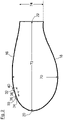
- the cross section of Fig. 2 lies within the longitudinal section 28 of the wind turbine rotor blade 10, close to the blade root 12.
- the aerodynamic profile has a relative thickness of about 40 %, calculated as the profile thickness 70 divided by the chord length 72, and a flat trailing edge 22 with a height 74 of about 20 % of the chord length 32.
- first fin 30 of a vortex generator of the first row 24 On the suction side 16, one can see a first fin 30 of a vortex generator of the first row 24.
- the first fin 30 has a trapezoidal shape with a leading end 34 formed by a short edge arranged approximately perpendicular to the surface of the suction side 16, and a trailing end 36 arranged approximately perpendicular to the surface of the suction side 16.
- second fin 32 of a vortex generator of the second row 26 has a trapezoidal shape with a leading end 38 formed by a short edge arranged approximately perpendicular to the surface of the suction side 16, and a trailing end 40 arranged approximately perpendicular to the surface of the suction side 16.
- the chordwise distance c is measured between the trailing ends 36 and 40 along the wind turbine rotor blade's surface.
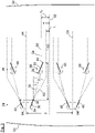
- FIG. 3 shows the positions of the vortex generators in greater detail, looking onto a section of the suction side 16 of the wind turbine rotor blade 10.
- the leading edge 20 is shown to the left, the trailing edge 22 is shown to the right of Fig. 3 .
- the first row 24 of vortex generators comprises a vortex generator having a first fin 30 and a further first fin 42 arranged symmetrically to a longitudinal axis 44 of this vortex generator.
- the distance d is indicated between the trailing end 36 of first fin 30 and the trailing end of first fin 42. It corresponds to a width of the vortex generator.
- Another, adjacent vortex generator of the first row 24 of vortex generators is arranged in a spanwise distance D. It comprises two fins 46, 48 and a longitudinal axis 50.
- the longitudinal axes 44, 50 of both vortex generators of the first row 24 of vortex generators are arranged in a generally chordwise direction. They define a centre line 52 arranged halfway between the longitudinal axes 44, 50.
- the spanwise distance D is measured between the longitudinal axes 44, 50.
- the second row 26 of vortex generators comprises a second fin 32 having a leading end 38 and a trailing end 40.
- the trailing end 40 is arranged in a spanwise distance x from the centre line 52, and in a chordwise distance c from the trailing end 36 of the first fin 30.
- the trailing end 40 is arranged in a specific surface area 54 shown with a shading.
- the range of spanwise positions x within the surface area 54 is defined by an upper limit xu given by a first line 56 and a second line 58 and by a lower limit X L given by a third line 60 and a fourth line 62.
- the first fin 30 When looking from the leading edge 20 at the air flow close to the suction side 16, the first fin 30 will generate a vortex rotating counter-clockwise and roughly covering the surface area 54 when flowing towards the trailing edge 22.
- the second fin 32 with its trailing end 40 arranged within this surface area 54 will not generate a new vortex, but will strengthen the vortex generated by the first fin 30.
- each of the second fins comprised in the second row 26 of vortex generators is arranged with reference to one of the first fins 30, 42, 46, 48 of the first row 24 of vortex generators, as has been explained in detail for the second fin 32, that is in a specific surface area shown with a shading.
- FIG. 3 also shows that the vortex generators of the first row 24 of vortex generators each comprise two first fins (30/42, and 46/48, respectively) connected to a common base plate 64, while each of the second fins of the vortex generators of the second row 26 of vortex generators is connected to a separate base plate 66.
Landscapes
- Engineering & Computer Science (AREA)
- Physics & Mathematics (AREA)
- Fluid Mechanics (AREA)
- Life Sciences & Earth Sciences (AREA)
- Sustainable Development (AREA)
- Sustainable Energy (AREA)
- Chemical & Material Sciences (AREA)
- Combustion & Propulsion (AREA)
- Mechanical Engineering (AREA)
- General Engineering & Computer Science (AREA)
- Wind Motors (AREA)
Abstract
• a first row of vortex generators comprising two adjacent vortex generators each having a longitudinal axis and two first fins having trailing ends arranged in a distance d from each other, wherein the two longitudinal axes define a centre line,
• a second row of vortex generators comprising a second fin having a trailing end arranged closer to the centre line than a leading end of the second fin,
• wherein the second fin is positioned with reference to the first fin that is arranged on the same side of the centre line as the second fin such that the trailing end of the second fin is arranged in a chordwise distance c from the trailing end of that first fin,
• wherein a distance x of the trailing end of the second fin from the centre line is within a certain defined range.
Description
- The invention relates to a wind turbine rotor blade with two rows of vortex generators.
- For optimum performance under various operating conditions, wind turbine rotor blades need to fulfil complex structural and aerodynamic requirements. With regard to the profile thickness, for example, a compromise has to be made between aerodynamic and structural performance. In an inner radius section of wind turbine rotor blades, structural requirements call for profiles having a large relative thickness of more than e.g. 30 %, while the strong curvature of these profiles may lead to flow separation. Flow separation has also been observed in various other surface regions of wind turbine rotor blades. To counteract such flow separation, it is well known to place vortex generators on the blade surface.
- The vortex generators are positioned obliquely, so that they have an angle of attack with respect to the local airflow, in order to create a vortex which draws energetic, rapidly moving outside air into the slow-moving boundary layer in contact with the blade surface. Vortex generators are used to trigger the transition from laminar flow to turbulent flow. A turbulent boundary layer is less likely to separate than a laminar one. As a consequence, a higher lift can be obtained. However, the vortex generators at the same time increase drag. For best results, vortex generators are generally positioned just before of an imaginary line where flow separation is expected.
- The document
EP 3 037 565 B1 discloses a wind turbine rotor blade having a main vortex generator configured to generate a main vortex and a secondary vortex generator configured to generate a second vortex, wherein the main vortex generator has a greater height than the secondary vortex generator. - The document
EP 2 129 908 B1 discloses a wind turbine rotor blade with two rows of vortex generators in accordance with the preamble of claim 1. The vortex generators of both rows have a relatively small height and for this reason are called micro vortex generators. - Starting therefrom, it is an object of the invention to improve the aerodynamic efficiency of a wind turbine rotor blade having two rows of vortex generators.
- This object is solved by the wind turbine rotor blade with the features of claim 1. Preferred aspects of the invention are given in the dependent claims.
- The wind turbine rotor blade has a blade root, a blade tip, a leading edge, a trailing edge, a first row of vortex generators and a second row of vortex generators,
• wherein the first row and the second row extend in a generally spanwise direction and the first row is arranged closer to the leading edge than the second row,
• wherein the first row comprises two adjacent vortex generators each having a longitudinal axis extending in a generally chordwise direction and two first fins arranged symmetrically to the longitudinal axis, wherein each of the two first fins has a leading end and a trailing end, wherein the trailing ends are arranged in a distance d from each other, wherein the distance d is larger than a distance between the leading ends, wherein the two longitudinal axes are arranged in a distance D from each other and define a centre line extending in a generally chordwise direction,
• wherein the second row of vortex generators comprises a second fin having a leading end and a trailing end, wherein the trailing end is arranged closer to the centre line than the leading end,
• wherein the second fin is positioned with reference to the first fin that is arranged on the same side of the centre line as the second fin and with its trailing end closer to the centre line than its leading end such that the trailing end of the second fin is arranged in a chordwise distance c from the trailing end of that first fin,
• wherein a distance x of the trailing end of the second fin from the centre line is within a range between
(i) an upper limit xu defined by:xu ≤ 0.30 D for c > 1.43 D - 3.57 d xu ≤ D/2 - d/2 - 0.14 c for c ≤ 1.43 D - 3.57 d and XL ≥ 0.07 D for c > 0.75 D - 0.87 d XL ≥ D/2 - d/2 - 0.58 c for c ≤ 0.75 D - 0.87 d - The wind turbine rotor blade in particular is designed for a wind turbine rotor with a horizontal axis. The blade root can be adapted for being fastened on a rotor hub. The spanwise direction generally extends from the blade root towards the blade tip, in particular parallel to a pitch axis or longitudinal axis of the wind turbine rotor blade. The wind turbine rotor blade has an aerodynamic profile with a suction side, a pressure side and a chord extending between a profile leading edge and a profile trailing edge. The chordwise direction corresponds to the direction of this chord, and is perpendicular to the longitudinal axis/pitch axis of the wind turbine rotor blade.
- The first row and the second row of vortex generators extend in a generally spanwise direction. In other words, the vortex generators of each row are placed along a line on the wind turbine rotor blade surface running from a first point closer to the blade root to a second point closer to the blade tip. These lines may be straight and/or parallel to the longitudinal axis/pitch axis of the wind turbine rotor blade. However, they may as well be inclined with regard to the longitudinal axis/pitch axis and/or comprise a curvature and/or one or more kinks. For example, the lines may be positioned at a fixed distance from the leading edge, either in absolute terms or in relation to the chord length varying in the spanwise direction. The distance from the leading edge may also vary in the spanwise direction, for example may it increase with increasing distance from the blade root. In this context, the feature that the first row is arranged closer to the leading edge than the second row means that a vortex generator of the first row at a given spanwise position is closer to the leading edge than a vortex generator of the second row at substantially the same spanwise position, so that the air flow reaches the second row only after having passed the first row.
- The first row comprises a plurality of vortex generators each having a longitudinal axis arranged in a generally chordwise direction. In other words, the vortex generators are aligned with a direction of the surrounding air flow, wherein some deviation between the direction of air flow, the longitudinal axis and/or the chordwise direction is possible.
- Each vortex generator of the first row comprises two first fins placed symmetrically with regard to its longitudinal axis. The first fins may be connected to each other via a base plate or via any other supporting structure mounted to the wind turbine rotor blade surface, but they may as well be mounted individually on the wind turbine rotor blade surface, without any other connecting member between the two first fins.
- The first fins as well as the second fin may be essentially planar, but they may also include some curvature. They are placed at an angle with reference to the longitudinal axis and hence to the direction of air flow. This angle may be in a range of about 10° to about 40°, for example. The fins may be placed generally perpendicular to a wind turbine rotor blade surface, in particular on the suction side. Each of the fins has a leading end and a trailing end, based upon where the air flow passes first. The leading end is the foremost part of the fin, the trailing end is the backmost part of the fin. As the fin may have any shape, e.g. rectangular, triangular, trapezoidal and/or including some curvature, the leading end may be a point or an edge. The same holds for the trailing end. The distance d is measured between the trailing ends of the first fins of a vortex generator of the first row of vortex generators. It corresponds to the overall width of these vortex generators.
- The longitudinal axes of two adjacent vortex generators of the first row define a centre line arranged halfway between the two longitudinal axes. If the longitudinal axes are exactly parallel, the centre line will be parallel to both of them. It is also possible that an angle is formed between the two longitudinal axes, should one or both of them deviate from the chordwise direction, e.g. by a few degrees. In this case, the centre line will be a bisecting line.
- The vortex generators of the second row comprise a second fin having a leading end and a trailing end, wherein the trailing end is arranged closer to the centre line. For defining the position of the trailing end of the second fin, reference is made to the position of the trailing end one of the first fins, namely of the first fin that is on the same side of the centre line and also has its trailing end closer to the centre line than its leading end. The chordwise distance between the trailing end of this first fin and the trailing end of the second fin is denoted distance c. It is measured along the wind turbine rotor blade surface, which may include some curvature. Hence, the chordwise distance c may not follow a straight line, but corresponds to an overall direction of air flow.
- In accordance with the invention, the spanwise position of the trailing end of the second fin lies in a specified area defined in terms of the spanwise distance x of this trailing end from the centre line. The spanwise distance x shall be measured along the wind turbine rotor blade surface as well, as has been explained for the chordwise distance c. The range of the spanwise distance x within the specified area is defined by upper and lower limits which depend on the chordwise distance c as indicated above. Both limits include a fixed value for the spanwise distance x which applies further away from the first row, and a value depending linearly on the chordwise distance c which applies closer to the first row. Together, the upper and lower limits define a strip-shaped surface area beginning at the trailing end of the specified first fin of the vortex generator of the first row, and then broadening with increasing distance from this trailing end.
- In operation, the area defined by the upper and lower limits corresponds to an extension of a vortex generated by the first fin. When the second fin has the same orientation with reference to the direction of air flow as the first fin, it tends to generate a vortex with the same rotation direction, either clockwise or counter-clockwise. Placing the trailing end of the second fin in the specified area therefore does not generate a new vortex, but rather strengthens or re-energises the vortex generated by the first fin. For this reason, it is believed that the second row of vortex generators helps avoiding flow separation while generating less additional drag than a second row of vortex generators placed outside of the specified area.
- In an aspect of the invention, the upper limit xu is defined by
xu ≤ 0.18 D for c > 1.19 D - 1.87 d xu ≤ D/2 - d/2 - 0.27 c for c ≤ 1.19 D - 1.87 d. Fig. 3 ). - In an aspect of the invention, the lower limit XL is defined by
XL ≥ 0.10 D for c > 0.85 D - 1.06 d XL ≥ D/2 - d/2 - 0.47 c for c ≤ 0.85 D - 1.06 d Fig. 3 ). - In an aspect of the invention, the chordwise distance c is larger than the distance d, in particular larger than twice the distance d. It has been found that the vortex strengthening effect works best when the distance c is at least as large as the distance d.
- In an aspect of the invention, the second row comprises a plurality of second fins, wherein each of the second fins is arranged with reference to one of the first fins as defined in claim 1. In this way, each of the second fins strengthens a vortex generated by one of the first fins.
- In an aspect of the invention, the two vortex generators of the first row are arranged in a longitudinal section of the wind turbine rotor blade in which the wind turbine rotor blade has an aerodynamic profile with a relative thickness of 0.35 or more. The relative thickness may also be 0.45 or larger. For this type of profiles, the second row of vortex generators is particularly useful.
- In an aspect of the invention, the aerodynamic profile has a flat trailing edge. The flat trailing edge helps limiting the curvature of the suction side and therefore avoiding flow separation. In combination with the inventive positioning of the second fin, optimal aerodynamic efficiency can be obtained.
- In an aspect of the invention, the flat trailing edge has a thickness of at least 2 % of a chord length of the aerodynamic profile. The thickness may also be at least 10 % or at least 15 % of the chord length.
- In an aspect of the invention, a vortex generator of the first row comprises a base plate mounted on a wind turbine rotor blade surface, wherein the two first fins of the vortex generator are connected to the base plate. This type of vortex generator is easy to install.
- In an aspect of the invention, a vortex generator of the second row comprises a base plate mounted on a wind turbine rotor blade surface, wherein a single second fin is connected to the base plate. In other words, each of the second fins of the second row of vortex generators is installed by means of a separate base plate. The defined spanwise positions of the second fins may include relatively large distances between adjacent second fins. Installing the second fins individually by means of separate, relatively small base plates instead of in pairs with relatively wide base plates can therefore lead to less disturbance of the air flow between adjacent second fins.
- In the following, the invention is explained in greater detail based on an embodiment shown in figures. The figures show:
- Fig. 1
- a wind turbine rotor blade in a schematic, perspective view,
- Fig. 2
- the wind turbine rotor blade of
Fig. 1 in cross section, - Fig. 3
- the wind turbine rotor blade of
Fig. 1 in a schematic view on a section of the suction side. - The wind
turbine rotor blade 10 ofFig. 1 has ablade root 12, ablade tip 14 and apitch axis 68. Thepitch axis 68 may also be referred to as longitudinal axis of the windturbine rotor blade 10. At theblade root 12, the windturbine rotor blade 10 has a cylindrical cross section and is adapted for attachment to a wind turbine rotor hub (not shown). The cross section with increasing distance from theblade root 12 transforms into an aerodynamic profile, as illustrated by the dotted lines. The surface of the windturbine rotor blade 10 facing the viewer forms asuction side 16, the opposite surface of the windturbine rotor blade 10 forms apressure side 18. Thepressure side 16 and thesuction side 18 both extend from a leadingedge 20 to a trailingedge 22. - A
first row 24 of vortex generators and asecond row 26 of vortex generators are arranged in a generally spanwise direction in alongitudinal section 28 of the windturbine rotor blade 10, on thesuction side 16. Thefirst row 24 of vortex generators is positioned closer to the leadingedge 20 than thesecond row 26 of vortex generators. In the embodiment ofFig. 1 , each vortex generator of thefirst row 24 and of thesecond row 26 comprises two fins. However, this is not mandatory in particular for thesecond row 26, in which one or more of the vortex generators may consist each of a single second fin only. - The cross section of
Fig. 2 lies within thelongitudinal section 28 of the windturbine rotor blade 10, close to theblade root 12. At this longitudinal position, the aerodynamic profile has a relative thickness of about 40 %, calculated as theprofile thickness 70 divided by thechord length 72, and aflat trailing edge 22 with aheight 74 of about 20 % of thechord length 32. - On the
suction side 16, one can see afirst fin 30 of a vortex generator of thefirst row 24. Thefirst fin 30 has a trapezoidal shape with aleading end 34 formed by a short edge arranged approximately perpendicular to the surface of thesuction side 16, and a trailingend 36 arranged approximately perpendicular to the surface of thesuction side 16. One can also see asecond fin 32 of a vortex generator of thesecond row 26. Thesecond fin 32 has a trapezoidal shape with aleading end 38 formed by a short edge arranged approximately perpendicular to the surface of thesuction side 16, and a trailingend 40 arranged approximately perpendicular to the surface of thesuction side 16. The chordwise distance c is measured between the trailing ends 36 and 40 along the wind turbine rotor blade's surface. -
Figure 3 shows the positions of the vortex generators in greater detail, looking onto a section of thesuction side 16 of the windturbine rotor blade 10. The leadingedge 20 is shown to the left, the trailingedge 22 is shown to the right ofFig. 3 . Thefirst row 24 of vortex generators comprises a vortex generator having afirst fin 30 and a furtherfirst fin 42 arranged symmetrically to alongitudinal axis 44 of this vortex generator. - The distance d is indicated between the trailing
end 36 offirst fin 30 and the trailing end offirst fin 42. It corresponds to a width of the vortex generator. - Another, adjacent vortex generator of the
first row 24 of vortex generators is arranged in a spanwise distance D. It comprises twofins longitudinal axis 50. Thelongitudinal axes first row 24 of vortex generators are arranged in a generally chordwise direction. They define acentre line 52 arranged halfway between thelongitudinal axes longitudinal axes - The
second row 26 of vortex generators comprises asecond fin 32 having a leadingend 38 and a trailingend 40. The trailingend 40 is arranged in a spanwise distance x from thecentre line 52, and in a chordwise distance c from the trailingend 36 of thefirst fin 30. The trailingend 40 is arranged in aspecific surface area 54 shown with a shading. The range of spanwise positions x within thesurface area 54 is defined by an upper limit xu given by afirst line 56 and asecond line 58 and by a lower limit XL given by athird line 60 and afourth line 62. - The
first line 56 is described by the term xu = D/2 - d/2 - 0.14 c and applies as an upper limit xu for the spanwise distance x where c ≤ 1.43 D - 3.57 d. The slope of -0.14 c corresponds to an angle α = 8°. Thesecond line 58 is described by the term xu = 0.30 D. - The
third line 60 is described by the term XL = D/2 - d/2 - 0.58 c and applies as a lower limit XL for the spanwise distance x where c ≤ 0.75 D - 0.87 d. The slope of -0.58 c corresponds to an angle β = 30°. Thefourth line 62 is described by the term XL = 0.07 D. - When looking from the leading
edge 20 at the air flow close to thesuction side 16, thefirst fin 30 will generate a vortex rotating counter-clockwise and roughly covering thesurface area 54 when flowing towards the trailingedge 22. Thesecond fin 32 with its trailingend 40 arranged within thissurface area 54 will not generate a new vortex, but will strengthen the vortex generated by thefirst fin 30. - One can see from
Fig. 3 that each of the second fins comprised in thesecond row 26 of vortex generators is arranged with reference to one of thefirst fins first row 24 of vortex generators, as has been explained in detail for thesecond fin 32, that is in a specific surface area shown with a shading. -
Figure 3 also shows that the vortex generators of thefirst row 24 of vortex generators each comprise two first fins (30/42, and 46/48, respectively) connected to acommon base plate 64, while each of the second fins of the vortex generators of thesecond row 26 of vortex generators is connected to aseparate base plate 66. -
- 10
- wind turbine rotor blade
- 12
- blade root
- 14
- blade tip
- 16
- suction side
- 18
- pressure side
- 20
- leading edge
- 22
- trailing edge
- 24
- first row of vortex generators
- 26
- second row of vortex generators
- 28
- longitudinal section
- 30
- first fin
- 32
- second fin
- 34
- leading end of
first fin 30 - 36
- trailing end of
first fin 30 - 38
- leading end of
second fin 32 - 40
- trailing end of
second fin 32 - 42
- first fin
- 44
- longitudinal axis
- 46
- first fin
- 48
- first fin
- 50
- longitudinal axis
- 52
- centre line
- 54
- surface area
- 56
- first line
- 58
- second line
- 60
- third line
- 62
- fourth line
- 64
- common base plate
- 66
- separate base plate
- 68
- pitch axis
- 70
- profile thickness
- 72
- chord length
- 74
- height
- α, β
- angles
- x
- distance of the trailing end of the second fin from the centre line
- xu
- upper limit of the value x
- XL
- lower limit of the value x
Claims (10)
- A wind turbine rotor blade (10) comprising a blade root (12), a blade tip (14), a leading edge (20), a trailing edge (22), a first row (24) of vortex generators and a second row (26) of vortex generators,• wherein the first row (24) and the second row (26) extend in a generally spanwise direction and the first row (24) is arranged closer to the leading edge (20) than the second row (26),• wherein the first row (24) comprises two adjacent vortex generators each having a longitudinal axis (44, 50) extending in a generally chordwise direction and two first fins (30, 42, 46, 48) arranged symmetrically to the longitudinal axis (44, 50), wherein each of the two first fins (30, 42, 46, 48) has a leading end (34) and a trailing end (36), wherein the trailing ends (36) are arranged in a distance d from each other, wherein the distance d is larger than a distance between the leading ends (34), wherein the two longitudinal axes (44, 50) are arranged in a distance D from each other and define a centre line (52) extending in a generally chordwise direction,• wherein the second row (24) of vortex generators comprises a second fin (32) having a leading end (38) and a trailing end (40), wherein the trailing end (40) is arranged closer to the centre line (52) than the leading end (38),• wherein the second fin (32) is positioned with reference to the first fin (30) that is arranged on the same side of the centre line (52) as the second fin (32) and with its trailing end (40) closer to the centre line (52) than its leading end (38) such that the trailing end (40) of the second fin (32) is arranged in a chordwise distance c from the trailing end (36) of that first fin (30),• characterised in that a distance x of the trailing end (40) of the second fin (32) from the centre line (52) is within the range between(i) an upper limit xu defined by:
xu ≤ 0.30 D for c > 1.43 D - 3.57 d xu ≤ D/2 - d/2 - 0.14 c for c ≤ 1.43 D - 3.57 d and (ii) a lower limit XL defined byXL ≥ 0.07 D for c > 0.75 D - 0.87 d XL ≥ D/2 - d/2 - 0.58 c for c ≤ 0.75 D - 0.87 d - The wind turbine rotor blade (10) of claim 1, characterised in that the upper limit xu is defined by
xu ≤ 0.18 D for c > 1.19 D - 1.87 d xu ≤ D/2 - d/2 - 0.27 c for c ≤ 1.19 D - 1.87 d. - The wind turbine rotor blade (10) of claim 1 or 2, characterised in that the lower limit XL is defined by
XL ≥ 0.10 D for c > 0.85 D - 1.06 d XL ≥ D/2 - d/2 - 0.47 c for c ≤ 0.85 D - 1.06 d - The wind turbine rotor blade (10) of any of the claims 1 to 3, characterised in that the chordwise distance c is larger than the distance d, in particular larger than twice the distance d.
- The wind turbine rotor blade (10) of any of the claims 1 to 4, characterised in that the second row (26) comprises a plurality of second fins (32), wherein each of the second fins (32) is arranged with reference to one of the first fins (30, 42, 46, 48) as defined in claim 1.
- The wind turbine rotor blade (10) of any of the claims 1 to 5, characterised in that the two vortex generators of the first row (24) are arranged in a longitudinal section (28) of the wind turbine rotor blade in which the wind turbine rotor blade (10) has an aerodynamic profile with a relative thickness of 0.35 or more.
- The wind turbine rotor blade (10) of any of the claims 1 to 6, characterised in that the aerodynamic profile has a flat trailing edge (22).
- The wind turbine rotor blade (10) of any of the claims 1 to 7, characterised in that the flat trailing edge (22) has a thickness of at least 2 % of a chord length (72) of the aerodynamic profile.
- The wind turbine rotor blade (10) of any of the claims 1 to 8, characterised in that a vortex generator of the first row (24) comprises a base plate (64) mounted on a wind turbine rotor blade surface, wherein the two first fins (30, 42) of the vortex generator are connected to the base plate (64).
- The wind turbine rotor blade (10) of any of the claims 1 to 9, characterised in that a vortex generator of the second row (26) comprises a base plate (66) mounted on a wind turbine rotor blade surface, wherein a single second fin (32) is connected to the base plate (66).
Priority Applications (5)
| Application Number | Priority Date | Filing Date | Title |
|---|---|---|---|
| ES21150476T ES3032399T3 (en) | 2021-01-07 | 2021-01-07 | A wind turbine rotor blade with two rows of vortex generators |
| EP21150476.6A EP4027006B1 (en) | 2021-01-07 | 2021-01-07 | A wind turbine rotor blade with two rows of vortex generators |
| PT211504766T PT4027006T (en) | 2021-01-07 | 2021-01-07 | A wind turbine rotor blade with two rows of vortex generators |
| DK21150476.6T DK4027006T3 (en) | 2021-01-07 | 2021-01-07 | WIND TURBINE ROTOR BLADE WITH TWO ROWS OF VORTEX GENERATORS |
| US17/563,868 US11525430B2 (en) | 2021-01-07 | 2021-12-28 | Wind turbine rotor blade with two rows of vortex generators |
Applications Claiming Priority (1)
| Application Number | Priority Date | Filing Date | Title |
|---|---|---|---|
| EP21150476.6A EP4027006B1 (en) | 2021-01-07 | 2021-01-07 | A wind turbine rotor blade with two rows of vortex generators |
Publications (2)
| Publication Number | Publication Date |
|---|---|
| EP4027006A1 true EP4027006A1 (en) | 2022-07-13 |
| EP4027006B1 EP4027006B1 (en) | 2025-03-05 |
Family
ID=74105883
Family Applications (1)
| Application Number | Title | Priority Date | Filing Date |
|---|---|---|---|
| EP21150476.6A Active EP4027006B1 (en) | 2021-01-07 | 2021-01-07 | A wind turbine rotor blade with two rows of vortex generators |
Country Status (5)
| Country | Link |
|---|---|
| US (1) | US11525430B2 (en) |
| EP (1) | EP4027006B1 (en) |
| DK (1) | DK4027006T3 (en) |
| ES (1) | ES3032399T3 (en) |
| PT (1) | PT4027006T (en) |
Families Citing this family (2)
| Publication number | Priority date | Publication date | Assignee | Title |
|---|---|---|---|---|
| EP4466184B1 (en) * | 2022-01-19 | 2025-12-10 | Power Curve ApS | Vortex generator |
| CN121593939A (en) * | 2025-12-26 | 2026-03-03 | 中材科技风电叶片股份有限公司 | Wind power blade and manufacturing method |
Citations (6)
| Publication number | Priority date | Publication date | Assignee | Title |
|---|---|---|---|---|
| EP2129908B1 (en) | 2007-03-20 | 2010-12-01 | Vestas Wind Systems A/S | Wind turbine blades with vortex generators |
| US20110229321A1 (en) * | 2008-12-02 | 2011-09-22 | Aerovortex Mills Ltd | Vortex dynamics turbine |
| US20150003985A1 (en) * | 2013-06-27 | 2015-01-01 | General Electric Company | Moveable surface features for wind turbine rotor blades |
| EP3037565B1 (en) | 2013-08-20 | 2017-11-29 | JFE Steel Corporation | Non-oriented electrical steel sheet having high magnetic flux density and motor |
| EP3473850A1 (en) * | 2017-10-20 | 2019-04-24 | Mitsubishi Heavy Industries, Ltd. | Method for determining arrangement position of vortex generator on wind turbine blade, method for producing wind turbine blade assembly, and wind turbine blade assembly |
| EP3473849A1 (en) * | 2017-10-20 | 2019-04-24 | Mitsubishi Heavy Industries, Ltd. | Wind turbine blade and method for determining arrangement of vortex generator on wind turbine blade |
Family Cites Families (8)
| Publication number | Priority date | Publication date | Assignee | Title |
|---|---|---|---|---|
| DK2007981T3 (en) * | 2006-04-02 | 2021-03-01 | Wobben Properties Gmbh | Windmill with slim wing |
| US8916795B2 (en) * | 2011-03-28 | 2014-12-23 | Lockheed Martin Corporation | Plasma actuated vortex generators |
| US9752559B2 (en) * | 2014-01-17 | 2017-09-05 | General Electric Company | Rotatable aerodynamic surface features for wind turbine rotor blades |
| US9476406B2 (en) | 2014-04-14 | 2016-10-25 | Siemens Aktiengesellschaft | Vortex generators aligned with trailing edge features on wind turbine blade |
| DK3037656T3 (en) | 2014-12-22 | 2017-03-13 | Siemens Ag | Rotor blade with vortex generators |
| US10400744B2 (en) * | 2016-04-28 | 2019-09-03 | General Electric Company | Wind turbine blade with noise reducing micro boundary layer energizers |
| JP6632553B2 (en) * | 2017-01-16 | 2020-01-22 | 三菱重工業株式会社 | Vortex generator and its installation method, windmill blade and wind power generator |
| EP3587799B1 (en) * | 2018-06-27 | 2025-06-18 | Siemens Gamesa Renewable Energy A/S | Aerodynamic structure |
-
2021
- 2021-01-07 PT PT211504766T patent/PT4027006T/en unknown
- 2021-01-07 EP EP21150476.6A patent/EP4027006B1/en active Active
- 2021-01-07 DK DK21150476.6T patent/DK4027006T3/en active
- 2021-01-07 ES ES21150476T patent/ES3032399T3/en active Active
- 2021-12-28 US US17/563,868 patent/US11525430B2/en active Active
Patent Citations (6)
| Publication number | Priority date | Publication date | Assignee | Title |
|---|---|---|---|---|
| EP2129908B1 (en) | 2007-03-20 | 2010-12-01 | Vestas Wind Systems A/S | Wind turbine blades with vortex generators |
| US20110229321A1 (en) * | 2008-12-02 | 2011-09-22 | Aerovortex Mills Ltd | Vortex dynamics turbine |
| US20150003985A1 (en) * | 2013-06-27 | 2015-01-01 | General Electric Company | Moveable surface features for wind turbine rotor blades |
| EP3037565B1 (en) | 2013-08-20 | 2017-11-29 | JFE Steel Corporation | Non-oriented electrical steel sheet having high magnetic flux density and motor |
| EP3473850A1 (en) * | 2017-10-20 | 2019-04-24 | Mitsubishi Heavy Industries, Ltd. | Method for determining arrangement position of vortex generator on wind turbine blade, method for producing wind turbine blade assembly, and wind turbine blade assembly |
| EP3473849A1 (en) * | 2017-10-20 | 2019-04-24 | Mitsubishi Heavy Industries, Ltd. | Wind turbine blade and method for determining arrangement of vortex generator on wind turbine blade |
Also Published As
| Publication number | Publication date |
|---|---|
| PT4027006T (en) | 2025-06-12 |
| US11525430B2 (en) | 2022-12-13 |
| EP4027006B1 (en) | 2025-03-05 |
| DK4027006T3 (en) | 2025-06-10 |
| ES3032399T3 (en) | 2025-07-18 |
| US20220213866A1 (en) | 2022-07-07 |
Similar Documents
| Publication | Publication Date | Title |
|---|---|---|
| EP2739528B1 (en) | A vortex generator arrangement for an airfoil | |
| US7914259B2 (en) | Wind turbine blades with vortex generators | |
| EP3348824B1 (en) | Vortex generator, installation method for the same, wind turbine blade, and wind turbine power generating apparatus | |
| AU2013213758B2 (en) | Wind turbine rotor blade | |
| EP2917571B1 (en) | A system and method for trailing edge noise reduction of a wind turbine blade | |
| CN104662287B (en) | Wind turbine blade with forming choked flow fence or flow diverter | |
| EP2815125B1 (en) | Wind turbine blade having a shaped stall fence or flow diverter | |
| EP2851553B1 (en) | Arrangement to reduce noise of a wind turbine rotor blade | |
| US10697427B2 (en) | Vortex generator and wind turbine blade assembly | |
| US20220186705A1 (en) | Wind turbine rotor blade configured for reduced trailing edge noise | |
| US11236722B2 (en) | Aerodynamic structure | |
| US11149707B2 (en) | Wind turbine blade and method for determining arrangement of vortex generator on wind turbine blade | |
| US20160177914A1 (en) | Rotor blade with vortex generators | |
| US10808676B2 (en) | Method for determining arrangement position of vortex generator on wind turbine blade, method for producing wind turbine blade assembly, and wind turbine blade assembly | |
| EP3390812B2 (en) | Splitter plate arrangement for a serrated wind turbine blade | |
| EP3696402A1 (en) | Noise reducer for a wind turbine rotor blade | |
| EP4027006B1 (en) | A wind turbine rotor blade with two rows of vortex generators | |
| US8226368B2 (en) | Wind turbine airfoil family | |
| US10907619B2 (en) | Lightning protection system for a rotor blade with a winglet | |
| CN114729619B (en) | Wind turbine rotor blade flow guide device and wind turbine rotor blade | |
| WO2013156479A1 (en) | A wind turbine blade having an angled stall fence |
Legal Events
| Date | Code | Title | Description |
|---|---|---|---|
| PUAI | Public reference made under article 153(3) epc to a published international application that has entered the european phase |
Free format text: ORIGINAL CODE: 0009012 |
|
| STAA | Information on the status of an ep patent application or granted ep patent |
Free format text: STATUS: THE APPLICATION HAS BEEN PUBLISHED |
|
| AK | Designated contracting states |
Kind code of ref document: A1 Designated state(s): AL AT BE BG CH CY CZ DE DK EE ES FI FR GB GR HR HU IE IS IT LI LT LU LV MC MK MT NL NO PL PT RO RS SE SI SK SM TR |
|
| STAA | Information on the status of an ep patent application or granted ep patent |
Free format text: STATUS: REQUEST FOR EXAMINATION WAS MADE |
|
| 17P | Request for examination filed |
Effective date: 20230109 |
|
| RBV | Designated contracting states (corrected) |
Designated state(s): AL AT BE BG CH CY CZ DE DK EE ES FI FR GB GR HR HU IE IS IT LI LT LU LV MC MK MT NL NO PL PT RO RS SE SI SK SM TR |
|
| GRAP | Despatch of communication of intention to grant a patent |
Free format text: ORIGINAL CODE: EPIDOSNIGR1 |
|
| STAA | Information on the status of an ep patent application or granted ep patent |
Free format text: STATUS: GRANT OF PATENT IS INTENDED |
|
| RIC1 | Information provided on ipc code assigned before grant |
Ipc: F03D 1/06 20060101AFI20240925BHEP |
|
| INTG | Intention to grant announced |
Effective date: 20241008 |
|
| GRAS | Grant fee paid |
Free format text: ORIGINAL CODE: EPIDOSNIGR3 |
|
| GRAA | (expected) grant |
Free format text: ORIGINAL CODE: 0009210 |
|
| STAA | Information on the status of an ep patent application or granted ep patent |
Free format text: STATUS: THE PATENT HAS BEEN GRANTED |
|
| AK | Designated contracting states |
Kind code of ref document: B1 Designated state(s): AL AT BE BG CH CY CZ DE DK EE ES FI FR GB GR HR HU IE IS IT LI LT LU LV MC MK MT NL NO PL PT RO RS SE SI SK SM TR |
|
| REG | Reference to a national code |
Ref country code: GB Ref legal event code: FG4D |
|
| REG | Reference to a national code |
Ref country code: CH Ref legal event code: EP |
|
| REG | Reference to a national code |
Ref country code: DE Ref legal event code: R096 Ref document number: 602021026974 Country of ref document: DE |
|
| REG | Reference to a national code |
Ref country code: IE Ref legal event code: FG4D |
|
| REG | Reference to a national code |
Ref country code: DK Ref legal event code: T3 Effective date: 20250604 |
|
| REG | Reference to a national code |
Ref country code: PT Ref legal event code: SC4A Ref document number: 4027006 Country of ref document: PT Date of ref document: 20250612 Kind code of ref document: T Free format text: AVAILABILITY OF NATIONAL TRANSLATION Effective date: 20250604 |
|
| PG25 | Lapsed in a contracting state [announced via postgrant information from national office to epo] |
Ref country code: RS Free format text: LAPSE BECAUSE OF FAILURE TO SUBMIT A TRANSLATION OF THE DESCRIPTION OR TO PAY THE FEE WITHIN THE PRESCRIBED TIME-LIMIT Effective date: 20250605 |
|
| PG25 | Lapsed in a contracting state [announced via postgrant information from national office to epo] |
Ref country code: FI Free format text: LAPSE BECAUSE OF FAILURE TO SUBMIT A TRANSLATION OF THE DESCRIPTION OR TO PAY THE FEE WITHIN THE PRESCRIBED TIME-LIMIT Effective date: 20250305 |
|
| REG | Reference to a national code |
Ref country code: NL Ref legal event code: MP Effective date: 20250305 |
|
| REG | Reference to a national code |
Ref country code: LT Ref legal event code: MG9D |
|
| PG25 | Lapsed in a contracting state [announced via postgrant information from national office to epo] |
Ref country code: NO Free format text: LAPSE BECAUSE OF FAILURE TO SUBMIT A TRANSLATION OF THE DESCRIPTION OR TO PAY THE FEE WITHIN THE PRESCRIBED TIME-LIMIT Effective date: 20250605 |
|
| PG25 | Lapsed in a contracting state [announced via postgrant information from national office to epo] |
Ref country code: HR Free format text: LAPSE BECAUSE OF FAILURE TO SUBMIT A TRANSLATION OF THE DESCRIPTION OR TO PAY THE FEE WITHIN THE PRESCRIBED TIME-LIMIT Effective date: 20250305 |
|
| PG25 | Lapsed in a contracting state [announced via postgrant information from national office to epo] |
Ref country code: LV Free format text: LAPSE BECAUSE OF FAILURE TO SUBMIT A TRANSLATION OF THE DESCRIPTION OR TO PAY THE FEE WITHIN THE PRESCRIBED TIME-LIMIT Effective date: 20250305 |
|
| REG | Reference to a national code |
Ref country code: ES Ref legal event code: FG2A Ref document number: 3032399 Country of ref document: ES Kind code of ref document: T3 Effective date: 20250718 |
|
| PG25 | Lapsed in a contracting state [announced via postgrant information from national office to epo] |
Ref country code: BG Free format text: LAPSE BECAUSE OF FAILURE TO SUBMIT A TRANSLATION OF THE DESCRIPTION OR TO PAY THE FEE WITHIN THE PRESCRIBED TIME-LIMIT Effective date: 20250305 Ref country code: GR Free format text: LAPSE BECAUSE OF FAILURE TO SUBMIT A TRANSLATION OF THE DESCRIPTION OR TO PAY THE FEE WITHIN THE PRESCRIBED TIME-LIMIT Effective date: 20250606 |
|
| REG | Reference to a national code |
Ref country code: AT Ref legal event code: MK05 Ref document number: 1773133 Country of ref document: AT Kind code of ref document: T Effective date: 20250305 |
|
| PG25 | Lapsed in a contracting state [announced via postgrant information from national office to epo] |
Ref country code: NL Free format text: LAPSE BECAUSE OF FAILURE TO SUBMIT A TRANSLATION OF THE DESCRIPTION OR TO PAY THE FEE WITHIN THE PRESCRIBED TIME-LIMIT Effective date: 20250305 |
|
| PG25 | Lapsed in a contracting state [announced via postgrant information from national office to epo] |
Ref country code: SE Free format text: LAPSE BECAUSE OF FAILURE TO SUBMIT A TRANSLATION OF THE DESCRIPTION OR TO PAY THE FEE WITHIN THE PRESCRIBED TIME-LIMIT Effective date: 20250305 |
|
| PG25 | Lapsed in a contracting state [announced via postgrant information from national office to epo] |
Ref country code: SM Free format text: LAPSE BECAUSE OF FAILURE TO SUBMIT A TRANSLATION OF THE DESCRIPTION OR TO PAY THE FEE WITHIN THE PRESCRIBED TIME-LIMIT Effective date: 20250305 |
|
| PG25 | Lapsed in a contracting state [announced via postgrant information from national office to epo] |
Ref country code: IT Free format text: LAPSE BECAUSE OF FAILURE TO SUBMIT A TRANSLATION OF THE DESCRIPTION OR TO PAY THE FEE WITHIN THE PRESCRIBED TIME-LIMIT Effective date: 20250305 Ref country code: PL Free format text: LAPSE BECAUSE OF FAILURE TO SUBMIT A TRANSLATION OF THE DESCRIPTION OR TO PAY THE FEE WITHIN THE PRESCRIBED TIME-LIMIT Effective date: 20250305 |
|
| PG25 | Lapsed in a contracting state [announced via postgrant information from national office to epo] |
Ref country code: AT Free format text: LAPSE BECAUSE OF FAILURE TO SUBMIT A TRANSLATION OF THE DESCRIPTION OR TO PAY THE FEE WITHIN THE PRESCRIBED TIME-LIMIT Effective date: 20250305 |
|
| PG25 | Lapsed in a contracting state [announced via postgrant information from national office to epo] |
Ref country code: CZ Free format text: LAPSE BECAUSE OF FAILURE TO SUBMIT A TRANSLATION OF THE DESCRIPTION OR TO PAY THE FEE WITHIN THE PRESCRIBED TIME-LIMIT Effective date: 20250305 Ref country code: EE Free format text: LAPSE BECAUSE OF FAILURE TO SUBMIT A TRANSLATION OF THE DESCRIPTION OR TO PAY THE FEE WITHIN THE PRESCRIBED TIME-LIMIT Effective date: 20250305 |
|
| PG25 | Lapsed in a contracting state [announced via postgrant information from national office to epo] |
Ref country code: RO Free format text: LAPSE BECAUSE OF FAILURE TO SUBMIT A TRANSLATION OF THE DESCRIPTION OR TO PAY THE FEE WITHIN THE PRESCRIBED TIME-LIMIT Effective date: 20250305 |
|
| PG25 | Lapsed in a contracting state [announced via postgrant information from national office to epo] |
Ref country code: SK Free format text: LAPSE BECAUSE OF FAILURE TO SUBMIT A TRANSLATION OF THE DESCRIPTION OR TO PAY THE FEE WITHIN THE PRESCRIBED TIME-LIMIT Effective date: 20250305 |
|
| PG25 | Lapsed in a contracting state [announced via postgrant information from national office to epo] |
Ref country code: IS Free format text: LAPSE BECAUSE OF FAILURE TO SUBMIT A TRANSLATION OF THE DESCRIPTION OR TO PAY THE FEE WITHIN THE PRESCRIBED TIME-LIMIT Effective date: 20250705 |
|
| REG | Reference to a national code |
Ref country code: DE Ref legal event code: R097 Ref document number: 602021026974 Country of ref document: DE |
|
| PLBE | No opposition filed within time limit |
Free format text: ORIGINAL CODE: 0009261 |
|
| STAA | Information on the status of an ep patent application or granted ep patent |
Free format text: STATUS: NO OPPOSITION FILED WITHIN TIME LIMIT |
|
| REG | Reference to a national code |
Ref country code: CH Ref legal event code: L10 Free format text: ST27 STATUS EVENT CODE: U-0-0-L10-L00 (AS PROVIDED BY THE NATIONAL OFFICE) Effective date: 20260114 |
|
| 26N | No opposition filed |
Effective date: 20251208 |
|
| PGFP | Annual fee paid to national office [announced via postgrant information from national office to epo] |
Ref country code: GB Payment date: 20260122 Year of fee payment: 6 |
|
| PGFP | Annual fee paid to national office [announced via postgrant information from national office to epo] |
Ref country code: ES Payment date: 20260217 Year of fee payment: 6 |
|
| PGFP | Annual fee paid to national office [announced via postgrant information from national office to epo] |
Ref country code: DK Payment date: 20260121 Year of fee payment: 6 Ref country code: DE Payment date: 20260120 Year of fee payment: 6 |
|
| PGFP | Annual fee paid to national office [announced via postgrant information from national office to epo] |
Ref country code: FR Payment date: 20260128 Year of fee payment: 6 |
|
| PGFP | Annual fee paid to national office [announced via postgrant information from national office to epo] |
Ref country code: TR Payment date: 20260106 Year of fee payment: 6 |
|
| PGFP | Annual fee paid to national office [announced via postgrant information from national office to epo] |
Ref country code: PT Payment date: 20251230 Year of fee payment: 6 |
|
| PG25 | Lapsed in a contracting state [announced via postgrant information from national office to epo] |
Ref country code: LT Free format text: LAPSE BECAUSE OF FAILURE TO SUBMIT A TRANSLATION OF THE DESCRIPTION OR TO PAY THE FEE WITHIN THE PRESCRIBED TIME-LIMIT Effective date: 20250305 |