EP4026759A1 - Truck or tractor vehicle with adjustable panhard bar and method for adjusting alignment of a truck or tractor vehicle cab relative to a truck or tractor vehicle frame - Google Patents
Truck or tractor vehicle with adjustable panhard bar and method for adjusting alignment of a truck or tractor vehicle cab relative to a truck or tractor vehicle frame Download PDFInfo
- Publication number
- EP4026759A1 EP4026759A1 EP21196516.5A EP21196516A EP4026759A1 EP 4026759 A1 EP4026759 A1 EP 4026759A1 EP 21196516 A EP21196516 A EP 21196516A EP 4026759 A1 EP4026759 A1 EP 4026759A1
- Authority
- EP
- European Patent Office
- Prior art keywords
- cab
- frame
- truck
- adjustable
- longitudinal centerline
- Prior art date
- Legal status (The legal status is an assumption and is not a legal conclusion. Google has not performed a legal analysis and makes no representation as to the accuracy of the status listed.)
- Granted
Links
Images




Classifications
-
- B—PERFORMING OPERATIONS; TRANSPORTING
- B62—LAND VEHICLES FOR TRAVELLING OTHERWISE THAN ON RAILS
- B62D—MOTOR VEHICLES; TRAILERS
- B62D33/00—Superstructures for load-carrying vehicles
- B62D33/06—Drivers' cabs
- B62D33/0604—Cabs insulated against vibrations or noise, e.g. with elastic suspension
-
- B—PERFORMING OPERATIONS; TRANSPORTING
- B62—LAND VEHICLES FOR TRAVELLING OTHERWISE THAN ON RAILS
- B62D—MOTOR VEHICLES; TRAILERS
- B62D33/00—Superstructures for load-carrying vehicles
- B62D33/08—Superstructures for load-carrying vehicles comprising adjustable means
-
- B—PERFORMING OPERATIONS; TRANSPORTING
- B62—LAND VEHICLES FOR TRAVELLING OTHERWISE THAN ON RAILS
- B62D—MOTOR VEHICLES; TRAILERS
- B62D33/00—Superstructures for load-carrying vehicles
- B62D33/08—Superstructures for load-carrying vehicles comprising adjustable means
- B62D33/10—Superstructures for load-carrying vehicles comprising adjustable means comprising means for the suspension of the superstructure on the frame
-
- B—PERFORMING OPERATIONS; TRANSPORTING
- B62—LAND VEHICLES FOR TRAVELLING OTHERWISE THAN ON RAILS
- B62D—MOTOR VEHICLES; TRAILERS
- B62D65/00—Designing, manufacturing, e.g. assembling, facilitating disassembly, or structurally modifying motor vehicles or trailers, not otherwise provided for
- B62D65/02—Joining sub-units or components to, or positioning sub-units or components with respect to, body shell or other sub-units or components
- B62D65/04—Joining preassembled modular units composed of sub-units performing diverse functions, e.g. engine and bonnet
Definitions
- the present invention relates to truck or tractor vehicles with an adjustable panhard bar and methods related to such vehicles.
- a cab When building trucks, a cab is typically mounted to a frame via a cab suspension that supports the cab proximate four corners of the cab.
- the suspension usually includes springs and dampers at each corner.
- a panhard bar is typically provided in connection with a rear portion of the suspension to resist lateral motion, provide stiffness to the cab suspension, and restrain the cab from detaching from the frame in the event of an accident.
- a cab may not be properly oriented relative to the frame.
- the cab and frame design is such that wind resistance is minimized and/or fuel economy is maximized by a particular cab and frame orientation, such as by having longitudinal centerlines of the cab and frame aligned, a misalignment may increase wind resistance and/or be detrimental to fuel economy.
- the cab and frame may move from a desired orientation to a less desirable orientation after a period of use, such as due to wear to springs or other components.
- a truck or tractor vehicle comprises a frame having a longitudinal centerline, an operator cab mounted relative to the frame via a cab suspension, the cab having a longitudinal centerline, the cab suspension comprising a front suspension and a rear suspension, the rear suspension comprising an adjustable panhard bar attached at a first end to the cab and attached at a second end to the frame, the adjustable panhard bar being adjustable in length to position the longitudinal centerline of the cab at a desired angle relative to the longitudinal centerline of the frame.
- a method for attaching a frame and an operator cab of a truck or tractor vehicle comprises mounting the cab relative to the frame via a cab suspension, the cab suspension comprising a front suspension and a rear suspension, the rear suspension comprising an adjustable panhard bar attached at a first end to the cab and attached at a second end to the frame, the adjustable panhard bar being adjustable in length, and adjusting a length of the adjustable panhard bar to position the longitudinal centerline of the cab at a desired angle relative to the longitudinal centerline of the frame.
- FIG. 1 A truck or tractor vehicle 21 according to an aspect of the present invention is shown in FIG. 1 and a frame 23 having a longitudinal centerline CF ( FIGS. 4 and 5 ) and an operator cab 25 mounted relative to the frame via a cab suspension 27, the cab having a longitudinal centerline CC ( FIGS. 4 and 5 ).
- the cab suspension 27 comprises a front suspension 29 and a rear suspension 31.
- the frame 23 typically comprises longitudinal portions (rails) 231 and transverse portions (cross members) 23t extending between the rails.
- the cab 25, likewise, typically comprises longitudinal portions (cab rails) 251 and transverse portions (cab cross members) 25t extending between the cab rails.
- the rear suspension 31 comprises an adjustable panhard bar 33 attached at a first end 35 to the cab 25 and attached at a second end 37 to a cross member 23t of the frame 23.
- the adjustable panhard bar 33 is adjustable in length to position the longitudinal centerline CC of the cab 25 at a desired angle relative to the longitudinal centerline CF of the frame 23 as seen in FIGS. 4 and 5 .
- the adjustable panhard bar 33 may be attached to one of the frame 23 and the cab 25 via a bracket or a suitable damping arrangement, such as the spring arrangement disclosed in U.S. Patent No. 6,758,294 , which is incorporated by reference.
- the front suspension 29 and the rear suspension 31 will ordinarily include spring and damping members, such as shown in U.S. Patent No. 6,758,294 , at at least the rear two and, ordinarily, at all four corners of the cab 25.
- the adjustable panhard bar 33 is ordinarily adjusted in length to position the longitudinal centerline CC of the cab 25 at a desired angle relative to the longitudinal centerline CF of the frame 23 so that wind resistance of the truck or tractor vehicle 21 is minimized and/or fuel economy is maximized. Ordinarily, wind resistance of the truck or tractor vehicle 21 is minimized and fuel economy is maximized by adjusting the adjustable panhard bar 33 in length to align the longitudinal centerline CC of the cab 25 and the longitudinal centerline CF of the frame 23.
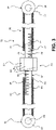
- the adjustable panhard bar 33 comprises a first bar component 39 having a first end attachable to the frame 23 and a threaded second end 41.
- the first end of the first bar component 39 is ordinarily the second end 37 of the adjustable panhard bar 33.
- the adjustable panhard bar 33 ordinarily further comprises a second bar component 43 having a first end attachable to the cab 25 and a threaded second end 45.
- the first end of the second bar component 43 is ordinarily the first end 35 of the adjustable panhard bar.
- the threaded second end 41 of the first bar component 39 ordinarily has a first thread 47 having a first hand (e.g., left-hand), and the threaded second end 45 of the second bar component 41 ordinarily has a second thread 49 having a second hand opposite the first hand (e.g., righthand).
- a linking member 51 is provided and ordinarily has a first threaded end 53 with a thread 55 that mates with the threaded second end 41 of the first bar component 39 and a second threaded end 57 with a thread 59 that mates with the threaded second end 45 of the second bar component 43.
- first and second threads 47 and 49 at the second threaded ends 41 and 45 of the first and second bar components 39 and 43, respectively, are internal, or female, threads and the threads 55 and 59 at the first and second threaded ends 53 and 57 of the linking member 51 are external, or male, threads.
- FIG. 6 it is, of course, also possible to provide a panhard bar 133 on which the first and second threads 147 and 149 at the second threaded ends 141 and 145 of the first and second bar components 139 and 143 are external threads and the first and second threads 155 and 159 at the first and second threaded ends 153 and 157 of the linking member 151 are internal threads.
- one of the first and second threads at the second threaded end of the first and second bar components be an external thread and the other an internal thread
- mating ones of the first and second threads at the first and second threaded ends of the linking member be an internal thread and the other an external thread
- the linking member 51 ordinarily further comprises a central, unthreaded portion 61.
- the central, unthreaded portion 61 ordinarily includes at least two opposite, longitudinally extending parallel surfaces 63, such as surfaces on a square or hexagonal shape, for facilitating gripping by a conventional wrench or automatic tool.
- the length of the panhard bar 33 will increase or decrease because of the provision of the first thread 47 and the second thread 49 on the first and second bar components (and because of the threads 55 and 59 on the linking member) having opposite hands.
- the first end of the first bar component 39 i.e. the second end 37 of the adjustable panhard bar 33
- the first end of the second bar component 43 i.e. the first end 35 of the adjustable panhard bar
- the second end 37 of the adjustable panhard bar 33 will ordinarily be attached to a suitable bracket arrangement 69 (such as the bracket arrangement shown in U.S. Patent No.
- the bracket arrangement need not include a damping component) on the frame 23 via a pin or bolt extending through the bushing 67 on the first end of the adjustable panhard bar and through a hole in a flange 73 on the bracket arrangement, and the first end 35 of the adjustable panhard bar 33 will be attached to a suitable bracket arrangement or frame portion 75 on the cab 25 via a pin or bolt through the bushing 67 on the second end of the adjustable panhard bar and through a hole in the bracket arrangement or frame portion on the cab.
- the adjustable panhard bar 33 further ordinarily comprises means, such as jam nuts 79, for locking the linking member 51 in position relative to the first bar component 39 and the second bar component 43.
- the front suspension 29 can comprise a first bracket arrangement 81 on a first (e.g., left) side of the cab 25 and a second bracket arrangement 83 on a second (e.g., right) side of the cab.
- the first bracket arrangement 81 can be configured to permit pivotal movement of the cab 25 relative to the frame 23 around an axis A
- the second bracket arrangement 83 can be configured to permit movement of the cab along an arc 85 of a circle relative to the frame, the circle having its center at the axis A.
- the cab 25 can pivot about the axis A.
- the panhard bar 33 will be adjustable in length only a small amount (e.g., about 1 ⁇ 2 inch or 10 mm) relative to the size of the frame 23 and cab 25, and the angle of the cab centerline CC relative to the frame centerline CF will also ordinarily only be adjustable a small amount, usually less than 1 degree.
- an angular adjustment of about 0.2 degrees of the cab centerline CC relative to the frame centerline CF will result in a lateral shift of about 10.5 mm of the rear end of the cab 25 relative to the frame 23.
- the panhard bar 33 can be constructed to permit substantially greater changes in length, and substantially greater angular adjustment.
- the second bracket arrangement 83 can comprise a first component 87 of the second bracket arrangement with a vertically extending elongated hole 89 therein.
- the first component 87 of the second bracket arrangement 83 will ordinarily be fixed to the frame 23 by any suitable means, such as welding, bolts, etc.
- the second bracket arrangement 83 can further comprise a second component 91 (shown in phantom) of the second bracket arrangement comprising a pin 93 (shown in phantom) fixed to the cab 25 by any suitable means (such as welding, bolts, etc.) and disposed in the elongated hole 89.
- the elongated hole 89 can be elongated to permit movement of the cab 23 along the arc 85 of the circle relative to the frame 25 as the length of the adjustable panhard bar 33 is changed.
- the elongated hole 89 may be in the shape of an arc.
- the first and second components 87 and 91 of the second bracket arrangement 83 will ordinarily be locked relative to each other, such as by a bolt on a threaded end of the pin 93 that fixes the pin relative to the elongated hole 89.
- the first bracket arrangement 81 comprises a first component 95 of the first bracket arrangement with a vertically extending hole 97 therein.
- the first component 95 of the first bracket arrangement 81 will ordinarily be fixed to the frame 23 by any suitable means, such as welding, bolts, etc.
- the first bracket arrangement 81 can further comprise a second component 99 of the first bracket arrangement comprising a pin 101 fixed to the cab 25 by any suitable means (such as welding, bolts, etc.) and disposed in the hole 97.
- the hole 97 will ordinarily be substantially circular and slightly larger in diameter than the pin 101 such that substantially only pivoting movement of the cab 25 relative to the frame 23 about the axis A centered in the hole 97 and pin 101 is permitted when the length of the adjustable panhard bar 33 is changed.
- the pin 101 will typically include a threaded end so that the first and second bracket components 95 and 99 can be bolted in place after the adjustable panhard bar 33 is adjusted so that the centerline CC of the cab 23 is at a desired angular orientation relative to the centerline CF of the frame.
- the frame has a longitudinal centerline CF and the cab has a longitudinal centerline CC.
- the cab 25 is mounted relative to the frame 23 via a cab suspension 27, the cab suspension comprising a front suspension 29 and a rear suspension 31.
- the rear suspension 31 comprises an adjustable panhard bar 33 attached at a first end 35 to the cab 25 and attached at a second end 37 to the frame 23, the adjustable panhard bar being adjustable in length.
- the method further comprises adjusting a length of the adjustable panhard bar 33 to position the longitudinal centerline CC of the cab 25 at a desired angle (usually but not necessarily a zero degree angle) relative to the longitudinal centerline CF of the frame 23.
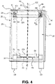
- FIG. 4 shows the centerline CF of the frame 23 and the centerline CC of the cab 25 (cab shown via solid lines) aligned when the panhard bar 33 is at a first length (shown via solid lines) and with the cab (shown via dashed lines) and the centerline of the cab rotated clockwise about the axis A and not aligned with the centerline of the frame when the panhard bar is at a longer second length (shown via dashed lines).
- FIG. 4 shows the centerline CF of the frame 23 and the centerline CC of the cab 25 (cab shown via solid lines) aligned when the panhard bar 33 is at a first length (shown via solid lines) and with the cab (shown via dashed lines) and the centerline of the
- FIG 5 shows the centerline CF of the frame 23 and the centerline CC of the cab 25 (cab shown via solid lines) aligned when the panhard bar 33 is at a first length (shown via solid lines) and with the cab (shown via dashed lines) and the centerline of the cab rotated counter-clockwise about the axis A and not aligned with the centerline of the frame when the panhard bar is at a shorter second length (shown via dashed lines).
- centerline CF of frame 23 and the centerline CC of the cab 25 will not necessarily be aligned when the pin 93 is in the center of the elongated hole 89 as illustrated and that aligning the centerlines may involve adjusting the panhard bar 33 to rotate the cab about the axis so that the pin is moved toward one end or the other of the elongated hole.
- the adjustable panhard bar 33 may be adjusted in length to position the longitudinal centerline CC of the cab 25 relative to the longitudinal centerline CF of the frame 23 so that wind resistance of the truck or tractor vehicle 21 is minimized. Minimizing wind resistance of the truck or tractor vehicle 21 will ordinarily be achieved by adjusting the adjustable panhard bar 33 in length to align the longitudinal centerline CC of the cab 25 relative to the longitudinal centerline CF of the frame 23.
- the adjustable panhard bar 33 may, alternatively or at the same time, be adjusted in length to position the longitudinal centerline CC of the cab 25 relative to the longitudinal centerline CF of the frame 23 so that fuel economy of the vehicle 21 is improved. Ordinarily, fuel economy will be improved as wind resistance is decreased.
- the truck or tractor vehicle and method according to the present invention facilitates correcting the positioning of a cab relative to a frame during manufacturing or after use. Because the correction can be accomplished via only a few bolt loosenings and tightenings, it can be achieved in a simple and inexpensive manner.
Landscapes
- Engineering & Computer Science (AREA)
- Chemical & Material Sciences (AREA)
- Combustion & Propulsion (AREA)
- Transportation (AREA)
- Mechanical Engineering (AREA)
- Manufacturing & Machinery (AREA)
- Body Structure For Vehicles (AREA)
Abstract
Description
- The present invention relates to truck or tractor vehicles with an adjustable panhard bar and methods related to such vehicles.
- When building trucks, a cab is typically mounted to a frame via a cab suspension that supports the cab proximate four corners of the cab. The suspension usually includes springs and dampers at each corner. A panhard bar is typically provided in connection with a rear portion of the suspension to resist lateral motion, provide stiffness to the cab suspension, and restrain the cab from detaching from the frame in the event of an accident.
- As a result of variations from standard dimensions in cabs and frames due to, for example, permissible manufacturing tolerances, it is possible that a cab may not be properly oriented relative to the frame. For example, if the cab and frame design is such that wind resistance is minimized and/or fuel economy is maximized by a particular cab and frame orientation, such as by having longitudinal centerlines of the cab and frame aligned, a misalignment may increase wind resistance and/or be detrimental to fuel economy.
- In addition to orientations of cab and frame that are less than optimal as the result of, e.g., manufacturing tolerances, the cab and frame may move from a desired orientation to a less desirable orientation after a period of use, such as due to wear to springs or other components.
- It is desirable to provide a way to correct the position a truck or tractor vehicle cab relative to a frame to place them in a desired angular orientation in spite of manufacturing tolerances, wear, or other factors that result in the cab and frame being oriented in a less than optimal manner. It is also desirable to be able to correct the position of the cab relative to the frame in a simple, inexpensive manner.
- According to an aspect of the present invention, a truck or tractor vehicle comprises a frame having a longitudinal centerline, an operator cab mounted relative to the frame via a cab suspension, the cab having a longitudinal centerline, the cab suspension comprising a front suspension and a rear suspension, the rear suspension comprising an adjustable panhard bar attached at a first end to the cab and attached at a second end to the frame, the adjustable panhard bar being adjustable in length to position the longitudinal centerline of the cab at a desired angle relative to the longitudinal centerline of the frame.
- According to another aspect of the present invention, a method for attaching a frame and an operator cab of a truck or tractor vehicle, the frame having a longitudinal centerline and the cab having a longitudinal centerline, comprises mounting the cab relative to the frame via a cab suspension, the cab suspension comprising a front suspension and a rear suspension, the rear suspension comprising an adjustable panhard bar attached at a first end to the cab and attached at a second end to the frame, the adjustable panhard bar being adjustable in length, and adjusting a length of the adjustable panhard bar to position the longitudinal centerline of the cab at a desired angle relative to the longitudinal centerline of the frame.
- The features and advantages of the present invention are well understood by reading the following detailed description in conjunction with the drawings in which like numerals indicate similar elements and in which:
-
FIG. 1 is a partial, side view of a truck or tractor vehicle according to an aspect of the invention;' -
FIG. 2 is partially cross-sectional view of the truck or tractor vehicle ofFIG. 1 taken at section 2-2; -
FIG. 3 is a partially cross-sectional view of an embodiment of an adjustable panhard bar according to an aspect of the present invention; -
FIG. 4 schematically shows adjustment of alignment of a truck or tractor vehicle cab relative to a truck or tractor vehicle frame; -
FIG. 5 schematically shows adjustment of alignment of a truck or tractor vehicle cab relative to a truck or tractor vehicle frame in a direction opposite to that shown inFIG. 4 ; and -
FIG. 6 is a partially cross-sectional view of another embodiment of an adjustable panhard bar according to an aspect of the present invention. - A truck or
tractor vehicle 21 according to an aspect of the present invention is shown inFIG. 1 and aframe 23 having a longitudinal centerline CF (FIGS. 4 and5 ) and anoperator cab 25 mounted relative to the frame via acab suspension 27, the cab having a longitudinal centerline CC (FIGS. 4 and5 ). Thecab suspension 27 comprises afront suspension 29 and arear suspension 31. As seen, for example, inFIG. 2 , theframe 23 typically comprises longitudinal portions (rails) 231 and transverse portions (cross members) 23t extending between the rails. Thecab 25, likewise, typically comprises longitudinal portions (cab rails) 251 and transverse portions (cab cross members) 25t extending between the cab rails. - As seen, for example, in
FIG. 2 , therear suspension 31 comprises anadjustable panhard bar 33 attached at afirst end 35 to thecab 25 and attached at asecond end 37 to across member 23t of theframe 23. Theadjustable panhard bar 33 is adjustable in length to position the longitudinal centerline CC of thecab 25 at a desired angle relative to the longitudinal centerline CF of theframe 23 as seen inFIGS. 4 and5 . Theadjustable panhard bar 33 may be attached to one of theframe 23 and thecab 25 via a bracket or a suitable damping arrangement, such as the spring arrangement disclosed inU.S. Patent No. 6,758,294 , which is incorporated by reference. In addition to theadjustable panhard bar 33, thefront suspension 29 and therear suspension 31 will ordinarily include spring and damping members, such as shown inU.S. Patent No. 6,758,294 , at at least the rear two and, ordinarily, at all four corners of thecab 25. - The
adjustable panhard bar 33 is ordinarily adjusted in length to position the longitudinal centerline CC of thecab 25 at a desired angle relative to the longitudinal centerline CF of theframe 23 so that wind resistance of the truck ortractor vehicle 21 is minimized and/or fuel economy is maximized. Ordinarily, wind resistance of the truck ortractor vehicle 21 is minimized and fuel economy is maximized by adjusting theadjustable panhard bar 33 in length to align the longitudinal centerline CC of thecab 25 and the longitudinal centerline CF of theframe 23. - As seen, for example, in
FIG. 3 , ordinarily, theadjustable panhard bar 33 comprises afirst bar component 39 having a first end attachable to theframe 23 and a threadedsecond end 41. The first end of thefirst bar component 39 is ordinarily thesecond end 37 of theadjustable panhard bar 33. Theadjustable panhard bar 33 ordinarily further comprises asecond bar component 43 having a first end attachable to thecab 25 and a threadedsecond end 45. The first end of thesecond bar component 43 is ordinarily thefirst end 35 of the adjustable panhard bar. - The threaded
second end 41 of thefirst bar component 39 ordinarily has afirst thread 47 having a first hand (e.g., left-hand), and the threadedsecond end 45 of thesecond bar component 41 ordinarily has asecond thread 49 having a second hand opposite the first hand (e.g., righthand). A linkingmember 51 is provided and ordinarily has a first threadedend 53 with athread 55 that mates with the threadedsecond end 41 of thefirst bar component 39 and a second threadedend 57 with athread 59 that mates with the threadedsecond end 45 of thesecond bar component 43. Ordinarily, the first andsecond threads ends second bar components threads ends member 51 are external, or male, threads. As seen inFIG. 6 , it is, of course, also possible to provide apanhard bar 133 on which the first andsecond threads ends second bar components second threads ends member 151 are internal threads. It is also possible to have one of the first and second threads at the second threaded end of the first and second bar components be an external thread and the other an internal thread, and mating ones of the first and second threads at the first and second threaded ends of the linking member be an internal thread and the other an external thread. - The linking
member 51 ordinarily further comprises a central, unthreadedportion 61. The central,unthreaded portion 61 ordinarily includes at least two opposite, longitudinally extendingparallel surfaces 63, such as surfaces on a square or hexagonal shape, for facilitating gripping by a conventional wrench or automatic tool. Depending upon which way the linkingmember 51 is turned relative to the stationaryfirst bar component 39 and the stationarysecond bar component 43, the length of thepanhard bar 33 will increase or decrease because of the provision of thefirst thread 47 and thesecond thread 49 on the first and second bar components (and because of thethreads - Ordinarily, the first end of the first bar component 39 (i.e. the
second end 37 of the adjustable panhard bar 33) and the first end of the second bar component 43 (i.e. thefirst end 35 of the adjustable panhard bar) each comprises ahole 65 and abushing 67 in the hole. As seen, for example, inFIG. 2 , thesecond end 37 of theadjustable panhard bar 33 will ordinarily be attached to a suitable bracket arrangement 69 (such as the bracket arrangement shown inU.S. Patent No. 6,758,294 that includes a damping component, however, the bracket arrangement need not include a damping component) on theframe 23 via a pin or bolt extending through thebushing 67 on the first end of the adjustable panhard bar and through a hole in aflange 73 on the bracket arrangement, and thefirst end 35 of theadjustable panhard bar 33 will be attached to a suitable bracket arrangement orframe portion 75 on thecab 25 via a pin or bolt through the bushing 67 on the second end of the adjustable panhard bar and through a hole in the bracket arrangement or frame portion on the cab. Theadjustable panhard bar 33 further ordinarily comprises means, such asjam nuts 79, for locking the linkingmember 51 in position relative to thefirst bar component 39 and thesecond bar component 43. - As seen, for example, in
FIGS. 4 and5 , thefront suspension 29 can comprise afirst bracket arrangement 81 on a first (e.g., left) side of thecab 25 and asecond bracket arrangement 83 on a second (e.g., right) side of the cab. Thefirst bracket arrangement 81 can be configured to permit pivotal movement of thecab 25 relative to theframe 23 around an axis A, and thesecond bracket arrangement 83 can be configured to permit movement of the cab along anarc 85 of a circle relative to the frame, the circle having its center at the axis A. In this way, as the length of the adjustable panhard bar changes, thecab 25 can pivot about the axis A. It will be appreciated thatFIGS. 4 and5 exaggerate the typical extent of adjustment that will be provided via theadjustable panhard bar 33. Ordinarily, thepanhard bar 33 will be adjustable in length only a small amount (e.g., about ½ inch or 10 mm) relative to the size of theframe 23 andcab 25, and the angle of the cab centerline CC relative to the frame centerline CF will also ordinarily only be adjustable a small amount, usually less than 1 degree. For example, in a presently preferred embodiment, an angular adjustment of about 0.2 degrees of the cab centerline CC relative to the frame centerline CF will result in a lateral shift of about 10.5 mm of the rear end of thecab 25 relative to theframe 23. Of course, if desired, thepanhard bar 33 can be constructed to permit substantially greater changes in length, and substantially greater angular adjustment. - The
second bracket arrangement 83 can comprise afirst component 87 of the second bracket arrangement with a vertically extendingelongated hole 89 therein. Thefirst component 87 of thesecond bracket arrangement 83 will ordinarily be fixed to theframe 23 by any suitable means, such as welding, bolts, etc. Thesecond bracket arrangement 83 can further comprise a second component 91 (shown in phantom) of the second bracket arrangement comprising a pin 93 (shown in phantom) fixed to thecab 25 by any suitable means (such as welding, bolts, etc.) and disposed in theelongated hole 89. Theelongated hole 89 can be elongated to permit movement of thecab 23 along thearc 85 of the circle relative to theframe 25 as the length of theadjustable panhard bar 33 is changed. Theelongated hole 89 may be in the shape of an arc. - After the
adjustable panhard bar 33 is adjusted so that the centerline CC of thecab 23 is at a desired angular orientation relative to the centerline CF of the frame, the first andsecond components second bracket arrangement 83 will ordinarily be locked relative to each other, such as by a bolt on a threaded end of thepin 93 that fixes the pin relative to theelongated hole 89. - The
first bracket arrangement 81 comprises afirst component 95 of the first bracket arrangement with a vertically extendinghole 97 therein. Thefirst component 95 of thefirst bracket arrangement 81 will ordinarily be fixed to theframe 23 by any suitable means, such as welding, bolts, etc. Thefirst bracket arrangement 81 can further comprise a second component 99 of the first bracket arrangement comprising apin 101 fixed to thecab 25 by any suitable means (such as welding, bolts, etc.) and disposed in thehole 97. Thehole 97 will ordinarily be substantially circular and slightly larger in diameter than thepin 101 such that substantially only pivoting movement of thecab 25 relative to theframe 23 about the axis A centered in thehole 97 andpin 101 is permitted when the length of theadjustable panhard bar 33 is changed. Thepin 101 will typically include a threaded end so that the first andsecond bracket components 95 and 99 can be bolted in place after theadjustable panhard bar 33 is adjusted so that the centerline CC of thecab 23 is at a desired angular orientation relative to the centerline CF of the frame. - In a method of the invention for attaching a
frame 23 and anoperator cab 25 of a truck ortractor vehicle 21, as seen inFIGS. 4 and5 , the frame has a longitudinal centerline CF and the cab has a longitudinal centerline CC. Thecab 25 is mounted relative to theframe 23 via acab suspension 27, the cab suspension comprising afront suspension 29 and arear suspension 31. Therear suspension 31 comprises anadjustable panhard bar 33 attached at afirst end 35 to thecab 25 and attached at asecond end 37 to theframe 23, the adjustable panhard bar being adjustable in length. - The method further comprises adjusting a length of the
adjustable panhard bar 33 to position the longitudinal centerline CC of thecab 25 at a desired angle (usually but not necessarily a zero degree angle) relative to the longitudinal centerline CF of theframe 23. For example,FIG. 4 shows the centerline CF of theframe 23 and the centerline CC of the cab 25 (cab shown via solid lines) aligned when thepanhard bar 33 is at a first length (shown via solid lines) and with the cab (shown via dashed lines) and the centerline of the cab rotated clockwise about the axis A and not aligned with the centerline of the frame when the panhard bar is at a longer second length (shown via dashed lines). Similarly,FIG. 5 shows the centerline CF of theframe 23 and the centerline CC of the cab 25 (cab shown via solid lines) aligned when thepanhard bar 33 is at a first length (shown via solid lines) and with the cab (shown via dashed lines) and the centerline of the cab rotated counter-clockwise about the axis A and not aligned with the centerline of the frame when the panhard bar is at a shorter second length (shown via dashed lines). It will be appreciated that the centerline CF offrame 23 and the centerline CC of thecab 25 will not necessarily be aligned when thepin 93 is in the center of theelongated hole 89 as illustrated and that aligning the centerlines may involve adjusting thepanhard bar 33 to rotate the cab about the axis so that the pin is moved toward one end or the other of the elongated hole. - The
adjustable panhard bar 33 may be adjusted in length to position the longitudinal centerline CC of thecab 25 relative to the longitudinal centerline CF of theframe 23 so that wind resistance of the truck ortractor vehicle 21 is minimized. Minimizing wind resistance of the truck ortractor vehicle 21 will ordinarily be achieved by adjusting theadjustable panhard bar 33 in length to align the longitudinal centerline CC of thecab 25 relative to the longitudinal centerline CF of theframe 23. Theadjustable panhard bar 33 may, alternatively or at the same time, be adjusted in length to position the longitudinal centerline CC of thecab 25 relative to the longitudinal centerline CF of theframe 23 so that fuel economy of thevehicle 21 is improved. Ordinarily, fuel economy will be improved as wind resistance is decreased. While it will ordinarily be desirable to align the longitudinal centerline CC of thecab 25 and the longitudinal centerline CF of theframe 23 to, inter alia, minimize wind resistance and improve fuel economy, there may be situations where it is desired to misalign the centerlines, and this is also possible via the present invention. - The truck or tractor vehicle and method according to the present invention facilitates correcting the positioning of a cab relative to a frame during manufacturing or after use. Because the correction can be accomplished via only a few bolt loosenings and tightenings, it can be achieved in a simple and inexpensive manner.
- In the present application, the use of terms such as "including" is open-ended and is intended to have the same meaning as terms such as "comprising" and not preclude the presence of other structure, material, or acts. Similarly, though the use of terms such as "can" or "may" is intended to be open-ended and to reflect that structure, material, or acts are not necessary, the failure to use such terms is not intended to reflect that structure, material, or acts are essential. To the extent that structure, material, or acts are presently considered to be essential, they are identified as such.
- While this invention has been illustrated and described in accordance with a preferred embodiment, it is recognized that variations and changes may be made therein without departing from the invention as set forth in the claims.
Claims (18)
- A truck or tractor vehicle, comprising:a frame having a longitudinal centerline;an operator cab mounted relative to the frame via a cab suspension, the cab having a longitudinal centerline;the cab suspension comprising a front suspension and a rear suspension, the rear suspension comprising an adjustable panhard bar attached at a first end to the cab and attached at a second end to the frame, the adjustable panhard bar being adjustable in length to position the longitudinal centerline of the cab at a desired angle relative to the longitudinal centerline of the frame.
- The truck or tractor vehicle as set forth in claim 1, wherein the adjustable panhard bar is adjusted in length to position the longitudinal centerline of the cab at a desired angle relative to the longitudinal centerline of the frame so that wind resistance of the truck or tractor vehicle is minimized.
- The truck or tractor vehicle as set forth in claim 2, wherein wind resistance of the truck or tractor vehicle is minimized by adjusting the adjustable panhard bar in length to align the longitudinal centerline of the cab and the longitudinal centerline of the frame.
- The truck or tractor vehicle as set forth in claim 1, wherein the adjustable panhard bar is adjusted in length to align the longitudinal centerline of the cab and the longitudinal centerline of the frame.
- The truck or tractor vehicle as set forth in claim 1, wherein the adjustable panhard bar comprisesa first bar component having a first end attachable to the frame and a threaded second end,a second bar component having a first end attachable to the cab and a threaded second end, the threaded second end of the first bar component having a first thread having a first hand, and the threaded second end of the second bar component having a second thread having a second hand opposite the first hand, anda linking member having a first threaded end that mates with the threaded second end of the first bar component and a second threaded end that mates with the threaded second end of the second bar component.
- The truck or tractor vehicle as set forth in claim 5, wherein the first threaded end and the second threaded end of the linking member are male threaded members.
- The truck or tractor vehicle as set forth in claim 5, wherein the linking member comprises a central, unthreaded portion.
- The truck or tractor vehicle as set forth in claim 7, wherein the central, unthreaded portion includes at least two opposite, longitudinally extending parallel surfaces.
- The truck or tractor vehicle as set forth in claim 5, wherein the first end of the first bar component and the first end of the second bar component each comprises a hole and a bushing in the hole.
- The truck or tractor vehicle as set forth in claim 5, wherein the adjustable panhard bar comprises means for locking the linking member in position relative to the first bar component and the second bar component.
- The truck or tractor vehicle as set forth in claim 1, wherein the front suspension comprises a first bracket arrangement on a first side of the cab and a second bracket arrangement on a second side of the cab, the first bracket arrangement being configured to permit pivotal movement of the cab relative to the frame around an axis, and the second bracket arrangement being configured to permit movement of the cab along an arc of a circle relative to the frame.
- The truck or tractor vehicle as set forth in claim 11, wherein the second bracket arrangement comprises a first component of the second bracket arrangement with a vertically extending hole therein, the first component of the second bracket arrangement being fixed to the frame, and a second component of the second bracket arrangement comprising a pin fixed to the cab and disposed in the hole, the hole being elongated to permit movement of the cab along the arc of the circle relative to the frame.
- The truck or tractor vehicle as set forth in claim 12, wherein the first bracket arrangement comprises a first component of the first bracket arrangement with a vertically extending hole therein, the first component of the first bracket arrangement being fixed to the frame, and a second component of the first bracket arrangement comprising a pin disposed in the hole, the hole being substantially circular such that substantially only pivoting movement of the cab relative to the frame is permitted.
- A method for attaching a frame and an operator cab of a truck or tractor vehicle, the frame having a longitudinal centerline and the cab having a longitudinal centerline, comprising:mounting the cab relative to the frame via a cab suspension, the cab suspension comprising a front suspension and a rear suspension, the rear suspension comprising an adjustable panhard bar attached at a first end to the cab and attached at a second end to the frame, the adjustable panhard bar being adjustable in length; andadjusting a length of the adjustable panhard bar to position the longitudinal centerline of the cab at a desired angle relative to the longitudinal centerline of the frame.
- The method as set forth in claim 14, comprising adjusting the adjustable panhard bar in length to position the longitudinal centerline of the cab relative to the longitudinal centerline of the frame so that wind resistance of the truck or tractor vehicle is minimized.
- The method as set forth in claim 15, comprising minimizing wind resistance of the truck or tractor vehicle by adjusting the adjustable panhard bar in length to align the longitudinal centerline of the cab and the longitudinal centerline of the frame.
- The method as set forth in claim 14, comprising adjusting the adjustable panhard bar in length to align the longitudinal centerline of the cab and the longitudinal centerline of the frame.
- The method as set forth in claim 14, comprising adjusting the adjustable panhard bar in length to position the longitudinal centerline of the cab relative to the longitudinal centerline of the frame so that fuel economy of the vehicle is improved.
Applications Claiming Priority (1)
| Application Number | Priority Date | Filing Date | Title |
|---|---|---|---|
| US17/085,163 US11639202B2 (en) | 2020-10-30 | 2020-10-30 | Truck or tractor vehicle with adjustable panhard bar and method for adjusting alignment of a truck or tractor vehicle cab relative to a truck or tractor vehicle frame |
Publications (2)
| Publication Number | Publication Date |
|---|---|
| EP4026759A1 true EP4026759A1 (en) | 2022-07-13 |
| EP4026759B1 EP4026759B1 (en) | 2025-08-06 |
Family
ID=77750118
Family Applications (1)
| Application Number | Title | Priority Date | Filing Date |
|---|---|---|---|
| EP21196516.5A Active EP4026759B1 (en) | 2020-10-30 | 2021-09-14 | Truck or tractor vehicle with adjustable panhard bar and method for adjusting alignment of a truck or tractor vehicle cab relative to a truck or tractor vehicle frame |
Country Status (4)
| Country | Link |
|---|---|
| US (1) | US11639202B2 (en) |
| EP (1) | EP4026759B1 (en) |
| CN (1) | CN114435494A (en) |
| AU (1) | AU2021240116A1 (en) |
Families Citing this family (2)
| Publication number | Priority date | Publication date | Assignee | Title |
|---|---|---|---|---|
| JP7728226B2 (en) * | 2022-04-20 | 2025-08-22 | 株式会社クボタ | Work vehicle |
| EP4635829A1 (en) * | 2024-04-16 | 2025-10-22 | Volvo Truck Corporation | A wind force adjustable panhard bar |
Citations (5)
| Publication number | Priority date | Publication date | Assignee | Title |
|---|---|---|---|---|
| US5553911A (en) * | 1994-12-15 | 1996-09-10 | Volvo Gm Heavy Truck Corporation | Heavy duty motor vehicle cab suspension |
| US6758294B2 (en) | 2002-06-10 | 2004-07-06 | Volvo Trucks North America, Inc. | Laterally damped panhard rod cab suspension |
| US20070267894A1 (en) * | 2005-05-19 | 2007-11-22 | Van Den Brink Joel D | Lateral control rod for a cab suspension system |
| US20120098227A1 (en) * | 2010-10-20 | 2012-04-26 | Christian Von Holst | Vehicle stabilization system |
| US20190100255A1 (en) * | 2017-10-02 | 2019-04-04 | CNH Industrial America, LLC | Suspension system for a work vehicle |
Family Cites Families (19)
| Publication number | Priority date | Publication date | Assignee | Title |
|---|---|---|---|---|
| US4053170A (en) | 1976-04-29 | 1977-10-11 | Westinghouse Air Brake Company | Panhard spring suspension arrangement for off-road vehicles |
| DE3817645C2 (en) * | 1988-05-25 | 1994-11-03 | Fraunhofer Ges Forschung | Driver's cabin with swivel system |
| GB2244745B (en) * | 1990-06-08 | 1995-02-15 | Schmidt Mfg & Equip | Cab mounting for a cleaning vehicle |
| EP0585774B1 (en) * | 1992-08-31 | 1996-04-24 | Deere & Company | Driver's cab suspension |
| GB2326137A (en) | 1997-06-06 | 1998-12-16 | New Holland Uk Ltd | Cab suspension for an agricultural vehicle |
| GB9719577D0 (en) * | 1997-09-16 | 1997-11-19 | Hendrickson Europ Limited | Suspension systems |
| AU2003262787A1 (en) | 2002-08-21 | 2004-03-11 | Delphi Technologies, Inc. | Controlled truck cab suspension |
| WO2004018242A2 (en) | 2002-08-21 | 2004-03-04 | Delphi Technologies, Inc. | Controlled truck cab suspension system |
| US6726272B1 (en) | 2002-10-24 | 2004-04-27 | International Truck Intellectual Property Company, Llc | Truck cab suspension system |
| US7648145B2 (en) * | 2007-06-27 | 2010-01-19 | Steve Wilson | Dynamically adjustable panhard bar |
| US7744149B2 (en) * | 2008-06-10 | 2010-06-29 | Agco Corporation | Cab suspension linkage system |
| US8459773B2 (en) | 2010-09-15 | 2013-06-11 | Electronics For Imaging, Inc. | Inkjet printer with dot alignment vision system |
| US8807633B2 (en) * | 2011-06-21 | 2014-08-19 | Cnh Industrial America Llc | Cab suspension system for an off-road vehicle |
| DE102012200670A1 (en) * | 2012-01-18 | 2013-07-18 | Zf Friedrichshafen Ag | Cab suspension system with roll stabilization |
| WO2013177288A1 (en) * | 2012-05-22 | 2013-11-28 | The Pullman Company | Driver's cab suspension |
| BR112015014717B1 (en) * | 2012-12-20 | 2021-12-14 | Cnh Industrial America Llc | WORK VEHICLE AND CAB SUSPENSION SYSTEM FOR ATTACHING A CAB FRAME TO A WORK VEHICLE CHASSIS FRAME |
| US8696002B1 (en) * | 2013-03-21 | 2014-04-15 | International Truck Intellectual Property Company, Llc | Roll center height variator |
| US9982413B2 (en) * | 2016-10-03 | 2018-05-29 | Cnh Industrial America Llc | Cab suspension system for a work vehicle |
| US10752298B2 (en) * | 2018-08-31 | 2020-08-25 | Cnh Industrial America Llc | Vibration dampening system for a work vehicle with elastomeric dampers |
-
2020
- 2020-10-30 US US17/085,163 patent/US11639202B2/en active Active
-
2021
- 2021-09-14 EP EP21196516.5A patent/EP4026759B1/en active Active
- 2021-09-23 CN CN202111114352.6A patent/CN114435494A/en active Pending
- 2021-09-27 AU AU2021240116A patent/AU2021240116A1/en active Pending
Patent Citations (5)
| Publication number | Priority date | Publication date | Assignee | Title |
|---|---|---|---|---|
| US5553911A (en) * | 1994-12-15 | 1996-09-10 | Volvo Gm Heavy Truck Corporation | Heavy duty motor vehicle cab suspension |
| US6758294B2 (en) | 2002-06-10 | 2004-07-06 | Volvo Trucks North America, Inc. | Laterally damped panhard rod cab suspension |
| US20070267894A1 (en) * | 2005-05-19 | 2007-11-22 | Van Den Brink Joel D | Lateral control rod for a cab suspension system |
| US20120098227A1 (en) * | 2010-10-20 | 2012-04-26 | Christian Von Holst | Vehicle stabilization system |
| US20190100255A1 (en) * | 2017-10-02 | 2019-04-04 | CNH Industrial America, LLC | Suspension system for a work vehicle |
Also Published As
| Publication number | Publication date |
|---|---|
| AU2021240116A1 (en) | 2022-05-19 |
| US11639202B2 (en) | 2023-05-02 |
| US20220135148A1 (en) | 2022-05-05 |
| EP4026759B1 (en) | 2025-08-06 |
| CN114435494A (en) | 2022-05-06 |
Similar Documents
| Publication | Publication Date | Title |
|---|---|---|
| US7942223B2 (en) | Vehicular radiator supporting apparatus | |
| KR100572264B1 (en) | Wheel angle adjuster of vehicle suspension system | |
| US8371596B2 (en) | Suspension system for heavy and vocational vehicles | |
| US7537225B2 (en) | Adjustable suspension leveling apparatus | |
| EP4026759B1 (en) | Truck or tractor vehicle with adjustable panhard bar and method for adjusting alignment of a truck or tractor vehicle cab relative to a truck or tractor vehicle frame | |
| US6659479B1 (en) | Adjustable suspension hanger assembly | |
| KR101338305B1 (en) | Cast Apex Adjustable V-type Torque Rod | |
| DE102010020816B4 (en) | Axis arrangement | |
| US5641175A (en) | Suspension system for automobile | |
| US8770602B1 (en) | Steering linkage and method for producing same | |
| US11130378B1 (en) | Adjustable control arm and method of using the same to adjust camber | |
| DE3925107A1 (en) | WHEEL SUSPENSION FOR A VEHICLE | |
| US8733768B1 (en) | Race car four link bar to chassis remotely adjustable brackets | |
| DE19743736A1 (en) | Motor vehicle front wheel suspension | |
| US6966567B2 (en) | One end adjustable torque rod | |
| DE102017201811B4 (en) | Rear axle suspension for a vehicle | |
| CA3241719A1 (en) | Adjustable control arm and ball joint assembly | |
| CA2312625C (en) | Adjustment mechanism for alignment of a pivot bushing, trailing beam and axle | |
| CN112124425B (en) | Wheel caster angle adjusts structure, suspension and vehicle | |
| EP1925470B1 (en) | Wheel suspension | |
| CA3239885A1 (en) | Adjustable control arm and ball joint assembly | |
| DE102023200676B3 (en) | Suspension strut, mounting system and motor vehicle | |
| CN213322543U (en) | Lower swing arm assembly | |
| US3104097A (en) | Torsion bar mounting construction | |
| DE102016111990B4 (en) | handlebar system |
Legal Events
| Date | Code | Title | Description |
|---|---|---|---|
| PUAI | Public reference made under article 153(3) epc to a published international application that has entered the european phase |
Free format text: ORIGINAL CODE: 0009012 |
|
| STAA | Information on the status of an ep patent application or granted ep patent |
Free format text: STATUS: THE APPLICATION HAS BEEN PUBLISHED |
|
| AK | Designated contracting states |
Kind code of ref document: A1 Designated state(s): AL AT BE BG CH CY CZ DE DK EE ES FI FR GB GR HR HU IE IS IT LI LT LU LV MC MK MT NL NO PL PT RO RS SE SI SK SM TR |
|
| STAA | Information on the status of an ep patent application or granted ep patent |
Free format text: STATUS: REQUEST FOR EXAMINATION WAS MADE |
|
| 17P | Request for examination filed |
Effective date: 20230110 |
|
| RBV | Designated contracting states (corrected) |
Designated state(s): AL AT BE BG CH CY CZ DE DK EE ES FI FR GB GR HR HU IE IS IT LI LT LU LV MC MK MT NL NO PL PT RO RS SE SI SK SM TR |
|
| GRAP | Despatch of communication of intention to grant a patent |
Free format text: ORIGINAL CODE: EPIDOSNIGR1 |
|
| STAA | Information on the status of an ep patent application or granted ep patent |
Free format text: STATUS: GRANT OF PATENT IS INTENDED |
|
| INTG | Intention to grant announced |
Effective date: 20250304 |
|
| GRAS | Grant fee paid |
Free format text: ORIGINAL CODE: EPIDOSNIGR3 |
|
| GRAA | (expected) grant |
Free format text: ORIGINAL CODE: 0009210 |
|
| STAA | Information on the status of an ep patent application or granted ep patent |
Free format text: STATUS: THE PATENT HAS BEEN GRANTED |
|
| AK | Designated contracting states |
Kind code of ref document: B1 Designated state(s): AL AT BE BG CH CY CZ DE DK EE ES FI FR GB GR HR HU IE IS IT LI LT LU LV MC MK MT NL NO PL PT RO RS SE SI SK SM TR |
|
| REG | Reference to a national code |
Ref country code: GB Ref legal event code: FG4D |
|
| REG | Reference to a national code |
Ref country code: CH Ref legal event code: EP |
|
| REG | Reference to a national code |
Ref country code: IE Ref legal event code: FG4D |
|
| REG | Reference to a national code |
Ref country code: DE Ref legal event code: R096 Ref document number: 602021035484 Country of ref document: DE |
|
| PGFP | Annual fee paid to national office [announced via postgrant information from national office to epo] |
Ref country code: DE Payment date: 20250926 Year of fee payment: 5 |
|
| PGFP | Annual fee paid to national office [announced via postgrant information from national office to epo] |
Ref country code: AT Payment date: 20251020 Year of fee payment: 5 |
|
| REG | Reference to a national code |
Ref country code: NL Ref legal event code: MP Effective date: 20250806 |
|
| PG25 | Lapsed in a contracting state [announced via postgrant information from national office to epo] |
Ref country code: IS Free format text: LAPSE BECAUSE OF FAILURE TO SUBMIT A TRANSLATION OF THE DESCRIPTION OR TO PAY THE FEE WITHIN THE PRESCRIBED TIME-LIMIT Effective date: 20251206 |
|
| PG25 | Lapsed in a contracting state [announced via postgrant information from national office to epo] |
Ref country code: NO Free format text: LAPSE BECAUSE OF FAILURE TO SUBMIT A TRANSLATION OF THE DESCRIPTION OR TO PAY THE FEE WITHIN THE PRESCRIBED TIME-LIMIT Effective date: 20251106 |
|
| REG | Reference to a national code |
Ref country code: LT Ref legal event code: MG9D |
|
| PG25 | Lapsed in a contracting state [announced via postgrant information from national office to epo] |
Ref country code: PT Free format text: LAPSE BECAUSE OF FAILURE TO SUBMIT A TRANSLATION OF THE DESCRIPTION OR TO PAY THE FEE WITHIN THE PRESCRIBED TIME-LIMIT Effective date: 20251209 |
|
| PG25 | Lapsed in a contracting state [announced via postgrant information from national office to epo] |
Ref country code: FI Free format text: LAPSE BECAUSE OF FAILURE TO SUBMIT A TRANSLATION OF THE DESCRIPTION OR TO PAY THE FEE WITHIN THE PRESCRIBED TIME-LIMIT Effective date: 20250806 |
|
| PG25 | Lapsed in a contracting state [announced via postgrant information from national office to epo] |
Ref country code: HR Free format text: LAPSE BECAUSE OF FAILURE TO SUBMIT A TRANSLATION OF THE DESCRIPTION OR TO PAY THE FEE WITHIN THE PRESCRIBED TIME-LIMIT Effective date: 20250806 Ref country code: NL Free format text: LAPSE BECAUSE OF FAILURE TO SUBMIT A TRANSLATION OF THE DESCRIPTION OR TO PAY THE FEE WITHIN THE PRESCRIBED TIME-LIMIT Effective date: 20250806 |
|
| PG25 | Lapsed in a contracting state [announced via postgrant information from national office to epo] |
Ref country code: GR Free format text: LAPSE BECAUSE OF FAILURE TO SUBMIT A TRANSLATION OF THE DESCRIPTION OR TO PAY THE FEE WITHIN THE PRESCRIBED TIME-LIMIT Effective date: 20251107 |
|
| PG25 | Lapsed in a contracting state [announced via postgrant information from national office to epo] |
Ref country code: SE Free format text: LAPSE BECAUSE OF FAILURE TO SUBMIT A TRANSLATION OF THE DESCRIPTION OR TO PAY THE FEE WITHIN THE PRESCRIBED TIME-LIMIT Effective date: 20250806 |
|
| PG25 | Lapsed in a contracting state [announced via postgrant information from national office to epo] |
Ref country code: LV Free format text: LAPSE BECAUSE OF FAILURE TO SUBMIT A TRANSLATION OF THE DESCRIPTION OR TO PAY THE FEE WITHIN THE PRESCRIBED TIME-LIMIT Effective date: 20250806 |
|
| PG25 | Lapsed in a contracting state [announced via postgrant information from national office to epo] |
Ref country code: BG Free format text: LAPSE BECAUSE OF FAILURE TO SUBMIT A TRANSLATION OF THE DESCRIPTION OR TO PAY THE FEE WITHIN THE PRESCRIBED TIME-LIMIT Effective date: 20250806 Ref country code: PL Free format text: LAPSE BECAUSE OF FAILURE TO SUBMIT A TRANSLATION OF THE DESCRIPTION OR TO PAY THE FEE WITHIN THE PRESCRIBED TIME-LIMIT Effective date: 20250806 |
|
| PG25 | Lapsed in a contracting state [announced via postgrant information from national office to epo] |
Ref country code: RS Free format text: LAPSE BECAUSE OF FAILURE TO SUBMIT A TRANSLATION OF THE DESCRIPTION OR TO PAY THE FEE WITHIN THE PRESCRIBED TIME-LIMIT Effective date: 20251106 |
|
| PG25 | Lapsed in a contracting state [announced via postgrant information from national office to epo] |
Ref country code: ES Free format text: LAPSE BECAUSE OF FAILURE TO SUBMIT A TRANSLATION OF THE DESCRIPTION OR TO PAY THE FEE WITHIN THE PRESCRIBED TIME-LIMIT Effective date: 20250806 |
|
| REG | Reference to a national code |
Ref country code: AT Ref legal event code: MK05 Ref document number: 1821544 Country of ref document: AT Kind code of ref document: T Effective date: 20250806 |
|
| PG25 | Lapsed in a contracting state [announced via postgrant information from national office to epo] |
Ref country code: RO Free format text: LAPSE BECAUSE OF FAILURE TO SUBMIT A TRANSLATION OF THE DESCRIPTION OR TO PAY THE FEE WITHIN THE PRESCRIBED TIME-LIMIT Effective date: 20250806 |
|
| PG25 | Lapsed in a contracting state [announced via postgrant information from national office to epo] |
Ref country code: SM Free format text: LAPSE BECAUSE OF FAILURE TO SUBMIT A TRANSLATION OF THE DESCRIPTION OR TO PAY THE FEE WITHIN THE PRESCRIBED TIME-LIMIT Effective date: 20250806 |
|
| PG25 | Lapsed in a contracting state [announced via postgrant information from national office to epo] |
Ref country code: DK Free format text: LAPSE BECAUSE OF FAILURE TO SUBMIT A TRANSLATION OF THE DESCRIPTION OR TO PAY THE FEE WITHIN THE PRESCRIBED TIME-LIMIT Effective date: 20250806 |
|
| PG25 | Lapsed in a contracting state [announced via postgrant information from national office to epo] |
Ref country code: AT Free format text: LAPSE BECAUSE OF FAILURE TO SUBMIT A TRANSLATION OF THE DESCRIPTION OR TO PAY THE FEE WITHIN THE PRESCRIBED TIME-LIMIT Effective date: 20250806 |
|
| PG25 | Lapsed in a contracting state [announced via postgrant information from national office to epo] |
Ref country code: IT Free format text: LAPSE BECAUSE OF FAILURE TO SUBMIT A TRANSLATION OF THE DESCRIPTION OR TO PAY THE FEE WITHIN THE PRESCRIBED TIME-LIMIT Effective date: 20250806 |
|
| PG25 | Lapsed in a contracting state [announced via postgrant information from national office to epo] |
Ref country code: CZ Free format text: LAPSE BECAUSE OF FAILURE TO SUBMIT A TRANSLATION OF THE DESCRIPTION OR TO PAY THE FEE WITHIN THE PRESCRIBED TIME-LIMIT Effective date: 20250806 |
|
| PG25 | Lapsed in a contracting state [announced via postgrant information from national office to epo] |
Ref country code: EE Free format text: LAPSE BECAUSE OF FAILURE TO SUBMIT A TRANSLATION OF THE DESCRIPTION OR TO PAY THE FEE WITHIN THE PRESCRIBED TIME-LIMIT Effective date: 20250806 Ref country code: SK Free format text: LAPSE BECAUSE OF FAILURE TO SUBMIT A TRANSLATION OF THE DESCRIPTION OR TO PAY THE FEE WITHIN THE PRESCRIBED TIME-LIMIT Effective date: 20250806 |
|
| REG | Reference to a national code |
Ref country code: CH Ref legal event code: H13 Free format text: ST27 STATUS EVENT CODE: U-0-0-H10-H13 (AS PROVIDED BY THE NATIONAL OFFICE) Effective date: 20260504 |