EP4026712A1 - Air outflow device, console and vehicle - Google Patents
Air outflow device, console and vehicle Download PDFInfo
- Publication number
- EP4026712A1 EP4026712A1 EP22150445.9A EP22150445A EP4026712A1 EP 4026712 A1 EP4026712 A1 EP 4026712A1 EP 22150445 A EP22150445 A EP 22150445A EP 4026712 A1 EP4026712 A1 EP 4026712A1
- Authority
- EP
- European Patent Office
- Prior art keywords
- air outflow
- air
- outlet
- section
- electric motor
- Prior art date
- Legal status (The legal status is an assumption and is not a legal conclusion. Google has not performed a legal analysis and makes no representation as to the accuracy of the status listed.)
- Withdrawn
Links
Images

Classifications
-
- B—PERFORMING OPERATIONS; TRANSPORTING
- B60—VEHICLES IN GENERAL
- B60H—ARRANGEMENTS OF HEATING, COOLING, VENTILATING OR OTHER AIR-TREATING DEVICES SPECIALLY ADAPTED FOR PASSENGER OR GOODS SPACES OF VEHICLES
- B60H1/00—Heating, cooling or ventilating devices
- B60H1/34—Nozzles; Air-diffusers
- B60H1/3414—Nozzles; Air-diffusers with means for adjusting the air stream direction
- B60H1/3421—Nozzles; Air-diffusers with means for adjusting the air stream direction using only pivoting shutters
-
- B—PERFORMING OPERATIONS; TRANSPORTING
- B60—VEHICLES IN GENERAL
- B60H—ARRANGEMENTS OF HEATING, COOLING, VENTILATING OR OTHER AIR-TREATING DEVICES SPECIALLY ADAPTED FOR PASSENGER OR GOODS SPACES OF VEHICLES
- B60H1/00—Heating, cooling or ventilating devices
- B60H1/34—Nozzles; Air-diffusers
- B60H1/3414—Nozzles; Air-diffusers with means for adjusting the air stream direction
-
- B—PERFORMING OPERATIONS; TRANSPORTING
- B60—VEHICLES IN GENERAL
- B60H—ARRANGEMENTS OF HEATING, COOLING, VENTILATING OR OTHER AIR-TREATING DEVICES SPECIALLY ADAPTED FOR PASSENGER OR GOODS SPACES OF VEHICLES
- B60H1/00—Heating, cooling or ventilating devices
- B60H1/00421—Driving arrangements for parts of a vehicle air-conditioning
- B60H1/00428—Driving arrangements for parts of a vehicle air-conditioning electric
-
- B—PERFORMING OPERATIONS; TRANSPORTING
- B60—VEHICLES IN GENERAL
- B60H—ARRANGEMENTS OF HEATING, COOLING, VENTILATING OR OTHER AIR-TREATING DEVICES SPECIALLY ADAPTED FOR PASSENGER OR GOODS SPACES OF VEHICLES
- B60H1/00—Heating, cooling or ventilating devices
- B60H1/34—Nozzles; Air-diffusers
- B60H2001/3471—Details of actuators
-
- B—PERFORMING OPERATIONS; TRANSPORTING
- B60—VEHICLES IN GENERAL
- B60H—ARRANGEMENTS OF HEATING, COOLING, VENTILATING OR OTHER AIR-TREATING DEVICES SPECIALLY ADAPTED FOR PASSENGER OR GOODS SPACES OF VEHICLES
- B60H1/00—Heating, cooling or ventilating devices
- B60H1/34—Nozzles; Air-diffusers
- B60H2001/3471—Details of actuators
- B60H2001/3478—Details of actuators acting on additional damper doors
-
- F—MECHANICAL ENGINEERING; LIGHTING; HEATING; WEAPONS; BLASTING
- F24—HEATING; RANGES; VENTILATING
- F24F—AIR-CONDITIONING; AIR-HUMIDIFICATION; VENTILATION; USE OF AIR CURRENTS FOR SCREENING
- F24F13/00—Details common to, or for air-conditioning, air-humidification, ventilation or use of air currents for screening
- F24F13/08—Air-flow control members, e.g. louvres, grilles, flaps or guide plates
- F24F13/10—Air-flow control members, e.g. louvres, grilles, flaps or guide plates movable, e.g. dampers
- F24F13/14—Air-flow control members, e.g. louvres, grilles, flaps or guide plates movable, e.g. dampers built up of tilting members, e.g. louvre
- F24F13/1426—Air-flow control members, e.g. louvres, grilles, flaps or guide plates movable, e.g. dampers built up of tilting members, e.g. louvre characterised by actuating means
Definitions
- the invention relates to the technical field of air outflow, and particularly provides an air outflow device, a console and a vehicle.
- the invention provides an air outflow device, in order to solve the above problem in the prior art whereby louvers in an air outflow device in a current vehicle needs to be manually turned to adjust an air outflow direction, bringing inconvenience in use.
- the air outflow device comprises a shell, wherein an air channel is formed in the shell, the air channel comprises an air inflow section and a first air outflow section and a second air outflow section separately in communication with the air inflow section, an opening/closing member and an air distribution member are rotatably disposed in the air inflow section, and an outlet of the first air outflow section and an outlet of the second air outflow section are respectively provided with a first louver structure and a second louver structure.
- the first driving member can not only adjust the longitudinal air outflow direction by driving the air distribution member, but also can drive the opening/closing member to control the opening/closing of the air inflow section, that is to say, the air distribution member and the opening/closing member are both controlled by means of one first driving member, thereby achieving two functions of adjusting the longitudinal air outflow direction and controlling the opening/closing of the air inflow section.
- an air outflow device In comparison with driving the air distribution member and the opening/closing member respectively by means of different driving members, such an air outflow device has a more compact structure, which is beneficial to a miniaturization design of the air outflow device.
- the first louver structure and the second louver structure can be both driven by means of one second driving member, such that the air outflow device has a more compact structure, which is more beneficial to the miniaturized design of the air outflow device.
- the transmission member is prevented from rotating due to its own weight or an external force when there is no need to rotate. Therefore, the situation is prevented that the first sliding structure and the second sliding structure cannot smoothly enter a slidable connection state due to the rotation of the transmission member, and the opening/closing member rotates is prevented from rotating due to the rotation of the transmission member, otherwise the air inflow section is mistakenly connected or disconnected.
- the first protrusion and the second protrusion can respectively enter the first helical groove and the second helical groove through the first auxiliary mounting groove and the second auxiliary mounting groove, facilitating assembly of the column sleeve and the connecting column.
- the first protrusion and the second protrusion can respectively enter the first helical groove and the second helical groove through the third auxiliary mounting groove and the fourth auxiliary mounting groove, facilitating assembly of the column sleeve and the connecting column.
- the first protrusion and the second protrusion can respectively either enter the first helical groove and the second helical groove through the first auxiliary mounting groove and the second auxiliary mounting groove or enter the first helical groove and the second helical groove through the third auxiliary mounting groove and the fourth auxiliary mounting groove, providing two ways of assembly, and further facilitating assembly of the column sleeve and the connecting column.
- the third sliding structure 50203 may be a sliding groove, a slider, etc.
- the fourth sliding structure 811 may accordingly be a slider, a sliding groove, etc.
- the shape of the outlet of the first air outflow section 12 is the same as that of the outlet of the second air outflow section 13 (for example, the outlet of the first air outflow section 12 and the outlet of the second air outflow section 13 shown in Fig. 1 are both rectangles with the same sizes), thereby providing a more favorable structural foundation for fluid design for the distribution of the air amount and the adjustment of the air outflow direction.
- the shape of the outlet of the first air outflow section 12 and the shape of the outlet of the second air outflow section 13 may also be different, which is not limited by the invention.
Landscapes
- Physics & Mathematics (AREA)
- Thermal Sciences (AREA)
- Engineering & Computer Science (AREA)
- Mechanical Engineering (AREA)
- Air-Flow Control Members (AREA)
Abstract
Description
- The invention relates to the technical field of air outflow, and particularly provides an air outflow device, a console and a vehicle.
- Vehicles are one of indispensable transportation means for people to go out. In order to improve comfort, an air outflow device is generally provided in a vehicle. In hot summer, the air outflow device can deliver cold air into the vehicle to reduce the temperature in the vehicle. In cold winter, the air outflow device can deliver warm air into the vehicle to increase the temperature in the vehicle. The configuration of the air outflow device enables a driver and a passenger to drive and ride the vehicle under appropriate temperature conditions regardless of freezing winter and sultry summer, greatly improving the comfort. Generally, in order to adjust an air outflow direction of the air outflow device, louvers are provided at an air outlet of the air outflow device, and when it is necessary to adjust the air outflow direction, the driver or the passenger needs to manually turn the louvers to adjust the air outflow direction, bringing inconvenience in use to the driver or the passenger.
- Therefore, there is a need in the art for a novel air outflow device, a console and a vehicle to solve the above problem.
- The invention provides an air outflow device, in order to solve the above problem in the prior art whereby louvers in an air outflow device in a current vehicle needs to be manually turned to adjust an air outflow direction, bringing inconvenience in use. The air outflow device comprises a shell, wherein an air channel is formed in the shell, the air channel comprises an air inflow section and a first air outflow section and a second air outflow section separately in communication with the air inflow section, an opening/closing member and an air distribution member are rotatably disposed in the air inflow section, and an outlet of the first air outflow section and an outlet of the second air outflow section are respectively provided with a first louver structure and a second louver structure. When air flows out of both the outlet of the first air outflow section and the outlet of the second air outflow section, an airflow flowing out of the outlet of the first air outflow section is capable of at least partially merging with an airflow flowing out of the outlet of the second air outflow section. A first driving member and a second driving member are disposed outside the air channel. The first driving member is capable of driving the opening/closing member to open/close the air inflow section so as to connect/disconnect the air inflow section, and is capable of driving the air distribution member to rotate so as to adjust an opening degree of an inlet of the first air outflow section or an inlet of the second air outflow section, adjusting an air outflow amount and a longitudinal air outflow direction. The second driving member is capable of driving the first louver structure and the second louver structure to swing together so as to adjust a transverse air outflow direction.
- With such a configuration, it is possible to change the longitudinal and transverse air outflow directions of the air outflow device by means of the first driving member and the second driving member without the need for manually turning the louvers to adjust the air outflow direction, such that the air outflow device is convenient to use. In addition, the first driving member can not only adjust the longitudinal air outflow direction by driving the air distribution member, but also can drive the opening/closing member to control the opening/closing of the air inflow section, that is to say, the air distribution member and the opening/closing member are both controlled by means of one first driving member, thereby achieving two functions of adjusting the longitudinal air outflow direction and controlling the opening/closing of the air inflow section. In comparison with driving the air distribution member and the opening/closing member respectively by means of different driving members, such an air outflow device has a more compact structure, which is beneficial to a miniaturization design of the air outflow device. Moreover, the first louver structure and the second louver structure can be both driven by means of one second driving member, such that the air outflow device has a more compact structure, which is more beneficial to the miniaturized design of the air outflow device.
- In a preferred technical solution of the air outflow device described above, the first driving member is a first electric motor, the air distribution member is fixedly connected to an output portion of the first electric motor, a first sliding structure and a stop member are further fixedly connected to the output portion of the first electric motor, a transmission member fixedly connected to the opening/closing member is disposed outside the air channel, and a second sliding structure is disposed on the transmission member; when the first sliding structure is not slidably connected to the second sliding structure, the stop member is capable of preventing the movement of the transmission member; and when the first sliding structure is slidably connected to the second sliding structure, the stop member is capable of disengaging from the transmission member to allow the movement of the transmission member under the action of the first sliding structure.
- With such a configuration, the transmission member is prevented from rotating due to its own weight or an external force when there is no need to rotate. Therefore, the situation is prevented that the first sliding structure and the second sliding structure cannot smoothly enter a slidable connection state due to the rotation of the transmission member, and the opening/closing member rotates is prevented from rotating due to the rotation of the transmission member, otherwise the air inflow section is mistakenly connected or disconnected.
- In a preferred technical solution of the air outflow device described above, the stop member is a stop block having an arc-shaped groove, and an arc-shaped edge slidably cooperating with the arc-shaped groove is formed on the transmission member.
- With such a configuration, it is possible to allow the stop member to restrict the movement of the transmission member in a timely manner by means of a relatively simple structure. In addition, such a structure is easy to machine, which is beneficial to improving the production efficiency.
- In a preferred technical solution of the air outflow device described above, the second driving member is a second electric motor, a connecting column is fixedly connected to an output portion of the second electric motor, a first protrusion and a second protrusion are formed on the connecting column, a column sleeve is fitted over the connecting column, a first helical groove and a second helical groove respectively corresponding to the first protrusion and the second protrusion are formed on the column sleeve, the first helical groove and the second helical groove have the same helical direction, and a first transmission rod and a second transmission rod are further fixed to the column sleeve; the first transmission rod is connected to the first louver structure by means of a first transmission assembly, and the second transmission rod is connected to the second louver structure by means of a second transmission assembly; a third sliding structure is disposed on the column sleeve, a fourth sliding structure slidably connected to the third sliding structure is further disposed in the shell, and the third sliding structure and the fourth sliding structure are relatively slidable only in an axial direction of the column sleeve; the second electric motor is capable of driving the column sleeve to rotate such that the first protrusion and the second protrusion respectively slide in the first helical groove and the second helical groove, the column sleeve moves in the axial direction, the first transmission rod and the second transmission rod then both move in the axial direction, and the first transmission assembly and the second transmission assembly are moved to drive the first louver structure and the second louver structure to swing together in the same direction.
- With such a configuration, it is possible that a structure of reversing the direction of movement between the output portion of the second electric motor and the first louver structure and between the output portion of the second electric motor and the second louver structure is convenient to maintain and has high transmission efficiency.
- In a preferred technical solution of the air outflow device described above, the first louver structure comprises a plurality of first louvers, and the first transmission assembly comprises a first mounting plate and at least one first connecting rod, wherein the first mounting plate is fixedly connected to the first transmission rod, the first connecting rods are equal in number to the first louvers and correspond to the first louvers on a one-to-one basis, a first end of each of the first connecting rods is hinged to the first mounting plate, and a second end of each of the first connecting rods is fixedly connected to the corresponding first louver; a first mounting frame is disposed in the outlet of the first air outflow section, and each of the first louvers is hinged to the first mounting frame; the second louver structure comprises a plurality of second louvers, the second transmission assembly comprises a second mounting plate and at least one second connecting rod, wherein the second mounting plate is fixedly connected to the second transmission rod, the second connecting rods are equal in number to the second louvers and correspond to the second louvers on a one-to-one basis, a first end of each of the second connecting rods is hinged to the second mounting plate, and a second end of each of the second connecting rods is fixedly connected to the corresponding second louver; a second mounting frame is disposed in the outlet of the second air outflow section, and each of the second louvers is hinged to the second mounting frame; and when the first transmission rod and the second transmission rod move in the same direction, the first mounting plate and the second mounting plate both move in the same direction and finally make all of the first louvers and all of the second louvers swing together in the same direction.
- With such a configuration, all the first louvers and all the second louvers can swing together in the same direction, that is to say, the outlet of the first air outflow section and the outlet of the second air outflow section have the same transverse air outflow direction, thereby facilitating adjustment of the air outflow direction in a longitudinal direction, avoiding adjustment of the longitudinal air outflow direction of part of the airflow due to the difference in the transverse air outflow directions of the outlet of the first air outflow section and the outlet of the second air outflow section.
- In a preferred technical solution of the air outflow device described above, a first auxiliary mounting groove and a second auxiliary mounting groove are formed in the end of the column sleeve close to the output portion of the second electric motor, the first auxiliary mounting groove is in communication with the end of the first helical groove close to the output portion of the second electric motor, and the second auxiliary mounting groove is in communication with the end of the second helical groove close to the output portion of the second electric motor; and/or a third auxiliary mounting groove and a fourth auxiliary mounting groove are formed in the end of the column sleeve remote from the output portion of the second electric motor, the third auxiliary mounting groove is in communication with the end of the first helical groove remote from the output portion of the second electric motor, and the fourth auxiliary mounting groove is in communication with the end of the second helical groove remote from the output portion of the second electric motor.
- With such a configuration, in the case where the first auxiliary mounting groove and the second auxiliary mounting groove are formed on the column sleeve, when the column sleeve and the connecting column are assembled, the first protrusion and the second protrusion can respectively enter the first helical groove and the second helical groove through the first auxiliary mounting groove and the second auxiliary mounting groove, facilitating assembly of the column sleeve and the connecting column.
- In the case where the third auxiliary mounting groove and the fourth auxiliary mounting groove are formed on the column sleeve, when the column sleeve and the connecting column are assembled, the first protrusion and the second protrusion can respectively enter the first helical groove and the second helical groove through the third auxiliary mounting groove and the fourth auxiliary mounting groove, facilitating assembly of the column sleeve and the connecting column.
- In the case where the first auxiliary mounting groove, the second auxiliary mounting groove, the third auxiliary mounting groove and the fourth auxiliary mounting groove are formed on the column sleeve, when the column sleeve and the connecting column are assembled, the first protrusion and the second protrusion can respectively either enter the first helical groove and the second helical groove through the first auxiliary mounting groove and the second auxiliary mounting groove or enter the first helical groove and the second helical groove through the third auxiliary mounting groove and the fourth auxiliary mounting groove, providing two ways of assembly, and further facilitating assembly of the column sleeve and the connecting column.
- In a preferred technical solution of the air outflow device described above, a rotation stop structure is disposed on the connecting column, a limiting structure is disposed on a mounting base of the second electric motor, and the limiting structure is capable of restricting a rotation stroke of the rotation stop structure to restrict a rotation stroke of the connecting column, thereby restricting swing ranges of the first louver structure and the second louver structure.
- With such a configuration, it is possible to restrict the swing ranges of the first louver structure and the second louver structure, and the structure is simple and is easy to machine.
- In a preferred technical solution of the air outflow device described above, a flow guiding structure is disposed between the outlet of the first air outflow section and the outlet of the second air outflow section, and the flow guiding structure comprises a first flow guiding portion and a second flow guiding portion, wherein a first end of the first flow guiding portion is connected to the outlet of the first air outflow section, and the first flow guiding portion is configured to be capable of guiding a flow in a tangential direction of the outlet of the first air outflow section; a first end of the second flow guiding portion is connected to the outlet of the second air outflow section, and the second flow guiding portion is configured to be capable of guiding a flow in a tangential direction of the outlet of the second air outflow section; and a second end of the first flow guiding portion is connected to a second end of the second flow guiding portion.
- In another aspect, the invention further provides a console. The console comprises a housing and the air outflow device as described above. The air outflow device is disposed in the housing, a covering portion is formed to extend on the housing, and the covering portion is capable of at least partially shielding the outlet of the first air outflow section and the outlet of the second air outflow section.
- With such a configuration, the console also has the beneficial effects of the foregoing air outflow device. Furthermore, the outlet of the first air outflow section and the outlet of the second air outflow section can be shielded to a certain extent, making the appearance more attractive.
- In a further aspect, the invention further provides a vehicle comprising the air outflow device as described above or the console as described above.
- With such a configuration, the vehicle also has the beneficial effects of the air outflow device or the console as described above.
-
-
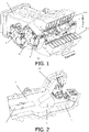
Fig. 1 is a schematic structural diagram of an air supply device of the invention, showing two air supply devices disposed together; -
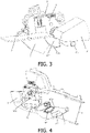
Fig. 2 is a schematic structural diagram of the air supply device of the invention, with part of a shell hidden; -
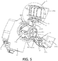
Fig. 3 is a schematic structural diagram of part of a structure of the air supply device of the invention, showing at least a stop member, a transmission member, a first driving member, and an opening/closing member; -
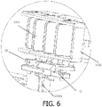
Fig. 4 is a schematic structural diagram of part of the structure of the air supply device of the invention, showing at least the shell, the stop member, and the transmission member; -
Fig. 5 is a schematic structural diagram of part of the structure of the air supply device of the invention, showing at least a first louver structure, a second louver structure, a connecting column, a column sleeve and a second driving member; -
Fig. 6 is an enlarged view of portion A inFig. 5 ; and -
Fig. 7 is an exploded view of the connecting column and the column sleeve in the air supply device of the invention. - 1. Shell; 11. Air inflow section; 12. First air outflow section; 1201. First louver structure; 1202. First mounting frame; 13. Second air outflow section; 1302. Second mounting frame; 1301. Second louver structure; 2. Opening/closing member; 3. Air distribution member; 4. First driving member; 401. First sliding structure; 402. Stop member; 5. Second driving member; 501. Connecting column; 5011. First protrusion; 5012. Second protrusion; 5013. Rotation stop structure; 502. Column sleeve; 50201. First transmission rod; 50202. Second transmission rod; 50203. Third sliding structure; 5021. First half column sleeve; 50211. First snap-fit portion; 5022. Second half column sleeve; 50221. Second snap-fit portion; 6. Transmission member; 601. Second sliding structure; 71. First mounting plate; 72. First connecting rod; 73. Second mounting plate; 74. Second connecting rod; 81. Mounting base of first electric motor; 811. Fourth sliding structure; 82. Mounting base of second electric motor; 821. Limiting structure; 822. Fourth sliding structure; 100. First helical groove; 200. Second helical groove; 300. First auxiliary mounting groove; 400. Second auxiliary mounting groove; 500. arc-shaped groove; 600. Arc-shaped edge.
- Preferred embodiments of the invention are described below with reference to the drawings. It should be understood by those skilled in the art that these embodiments are only for explaining the technical principles of the invention and are not intended to limit the scope of protection of the invention.
- It should be noted that, in the description of the invention, the terms that indicate the direction or positional relationship, such as "center", "upper", "lower", "left", "right", "vertical", "horizontal", "inner", "outer", "front", "rear", "transverse" and "longitudinal" are based on the direction or positional relationship shown in the figures, which is merely for ease of description instead of indicating or implying that the device or element must have a particular orientation and be constructed and operated in a particular orientation, and therefore, should not be construed as limiting the invention. In addition, the terms "first", "second", "third" and "fourth" are for descriptive purposes only and should not be construed as indicating or implying relative importance.
- In addition, it should also be noted that, in the description of the invention, the terms "dispose", "mount", "engage" and "connect" should be interpreted in a broad sense unless explicitly defined and limited otherwise, which, for example, may mean a fixed connection, a detachable connection or an integral connection; may mean a mechanical connection or an electrical connection; and may mean a direct connection, an indirect connection by means of an intermediary, or internal communication between two elements. For those skilled in the art, the specific meaning of the above-mentioned terms in the invention can be interpreted according to the specific situation.
- As shown in
Figs. 1 to 7 , the invention provides an air outflow device (two air outflow devices are shown inFig. 1 ). The air outflow device comprises a shell 1. An air channel is formed in the shell 1, the air channel comprises anair inflow section 11 and a firstair outflow section 12 and a secondair outflow section 13 respectively in communication with theair inflow section 11. An opening/closingmember 2 and anair distribution member 3 are rotatably disposed in theair inflow section 11, and an outlet of the firstair outflow section 12 and an outlet of the secondair outflow section 13 are respectively provided with afirst louver structure 1201 and asecond louver structure 1301. When air flows out of both the outlet of the firstair outflow section 12 and the outlet of the secondair outflow section 13, an airflow flowing out of the outlet of the firstair outflow section 12 can at least partially merge with an airflow flowing out of the outlet of the secondair outflow section 13. Afirst driving member 4 and asecond driving member 5 are disposed outside the air channel. Thefirst driving member 4 can drive the opening/closingmember 2 to open/close theair inflow section 11 so as to connect/disconnect theair inflow section 11 and can drive theair distribution member 3 to rotate so as to adjust an opening degree of an inlet of the firstair outflow section 12 or an inlet of the secondair outflow section 13, adjusting an air outflow amount and a longitudinal air outflow direction. Thesecond driving member 5 can drive thefirst louver structure 1201 and thesecond louver structure 1301 to swing together so as to adjust a transverse air outflow direction. - It should be noted that the air outflow device of the invention may be applied to a vehicle, or be applied to a household air conditioner or other equipment in which an airflow needs to be delivered. Such an adjustment of application objects of the air outflow device does not limit the invention, which shall be limited within the scope of protection of the invention. The
air inflow section 11 is in communication with an air source (for example, a fan and an air conditioning system of a vehicle). When the opening/closingmember 2 opens theair inflow section 11, the airflow from the air source can flow through theair inflow section 11, the air outflow device can deliver the airflow from the air source out of the outlet of the firstair outflow section 12 and the outlet of the secondair outflow section 13. When the opening/closingmember 2 closes theair inflow section 11, since theair inflow section 11 is disconnected, the airflow from the air source cannot flow through theair inflow section 11, and the outlet of the firstair outflow section 12 and the outlet of the secondair outflow section 13 in the air outflow device stop delivering the airflow. - The
air distribution member 3 rotates to adjust the opening degree of the inlet of the firstair outflow section 12 or the inlet of the secondair outflow section 13. That is to say, theair distribution member 3 can alternatively block the inlet of the firstair outflow section 12 or the inlet of the secondair outflow section 13. When the inlet of the firstair outflow section 12 is blocked, the inlet of the firstair outflow section 12 can be completely or partially blocked. When the inlet of the secondair outflow section 13 is blocked, the inlet of the secondair outflow section 13 can be completely or partially blocked. In the case where the firstair outflow section 12 is located above the second air outflow section 13 (it is the case shown inFig. 1 ), when theair distribution member 3 completely blocks the inlet of the firstair outflow section 12, all the air is distributed to the secondair outflow section 13, at this moment, the blown air will be blown downwards at the maximum limit angle, and the longitudinal air outflow direction is the air outflow direction of the secondair outflow section 13 in a longitudinal direction. When theair distribution member 3 completely blocks the inlet of the secondair outflow section 13, all the air is distributed to the firstair outflow section 12, at this moment, the blown air will be blown upwards at the maximum limit angle, and the longitudinal air outflow direction is the air outflow direction of the firstair outflow section 12 in the longitudinal direction. When theair distribution member 3 partially blocks the inlet of the firstair outflow section 12, most of the air is distributed to the secondair outflow section 13, and a small part of the air is distributed to the firstair outflow section 12, at this moment, the air blown out by the secondair outflow section 13 is partially offset by the air blown out by the firstair outflow section 12, thereby making the longitudinal air outflow direction slightly downward compared with the air outflow direction when theair distribution member 3 completely blocks the inlet of the firstair outflow section 12. When theair distribution member 3 partially blocks the inlet of the secondair outflow section 13, most of the air is distributed to the firstair outflow section 12, and a small part of the air is distributed to the secondair outflow section 13, at this moment, the air blown by the firstair outflow section 12 is partially offset by the air blown by the secondair outflow section 13, thereby making the longitudinal air outflow direction slightly upward compared with the air outflow direction when theair distribution member 3 completely blocks the inlet of the secondair outflow section 13. - In the above description, the opening/closing
member 2 may use an opening/closing plate, an opening/closing block, etc., and those skilled in the art would have been able to flexibly the specific structure of the opening/closingmember 2 in practical applications as long as the opening/closingmember 2 can open/close theair inflow section 11 under the drive of the first drivingmember 4 so as to connect/disconnect theair inflow section 11. Theair distribution member 3 may be a sector-shaped air distribution block, a circular air distribution block, etc., and those skilled in the art would have been able to flexibly the specific structure of theair distribution member 3 in practical applications as long as theair distribution member 3 can rotate under the drive of the first drivingmember 4 to adjust the opening degree of the inlet of the firstair outflow section 12 or the inlet of the secondair outflow section 13, adjusting the air outflow amount and the longitudinal air outflow direction. - Preferably, as shown in
Figs. 3 and 4 , the first drivingmember 4 is a first electric motor, theair distribution member 3 is fixedly connected to an output portion of the first electric motor, a first slidingstructure 401 and astop member 402 are further fixedly connected to the output portion of the first electric motor, atransmission member 6 fixedly connected to the opening/closingmember 2 is disposed outside the air channel, and a second slidingstructure 601 is disposed on thetransmission member 6. When the first slidingstructure 401 is not slidably connected to the second slidingstructure 601, thestop member 402 can prevent the movement of thetransmission member 6. When the first slidingstructure 401 is slidably connected to the second slidingstructure 601, thestop member 402 can disengage from thetransmission member 6 to allow the movement of thetransmission member 6 under the action of the first slidingstructure 401. In the case shown inFigs. 3 and 4 , the first slidingstructure 401 is a slider, and the second slidingstructure 601 is a sliding groove. During rotation of the output portion of the first electric motor in the counterclockwise direction, the slider is gradually slidably connected to the sliding groove. When the slider starts to be slidably connected to the sliding groove, thestop member 402 exactly disengages from thetransmission member 6. During relative sliding between the slider and the sliding groove, thetransmission member 6 rotates under the action of the slider. When the slider slides to the tail end of the sliding groove (at this moment, the slider cannot continue to slide along the sliding groove), the opening/closingmember 2 rotates to a position where theair inflow section 11 can be closed, so as to disconnect theair inflow section 11, such that the airflow from the air source cannot flow through theair inflow section 11. Later, the output portion of the first electric motor can rotate in the clockwise direction, at this moment, the slider slides out of the sliding groove. During the sliding, thetransmission member 6 rotates under the action of the slider such that the opening/closingmember 2 rotates to a position where theair inflow section 11 can be opened, so as to connect theair inflow section 11, and at the moment when the slider is separated from the sliding groove, thestop member 402 comes into contact with thetransmission member 6 again and prevents the movement of thetransmission member 6. - Instead of the electric motor, the first driving
member 4 may also be a combined structure of a gear, a rack and an air cylinder. Specifically, the air cylinder is directly connected to the rack, the rack meshes with the gear, and a shaft passes through a central hole of the gear to serve as an output shaft. Those skilled in the art would have been able to flexibly the specific structure of the first drivingmember 4 in practical applications, and such an adjustment and change in the specific structure of the first drivingmember 4 do not limit the invention, which shall be limited within the scope of protection of the invention. The first slidingstructure 401 may be a sliding groove, a slider, etc., the second slidingstructure 601 may accordingly be a slider, a sliding groove, etc., and thetransmission member 6 may be a transmission plate, a transmission rod, etc. Those skilled in the art would have been able to flexibly the specific structures of the first slidingstructure 401, the second slidingstructure 601 and thetransmission member 6 in practical applications, and such adjustments and changes in the specific structures of the first slidingstructure 401, the second slidingstructure 601 and thetransmission member 6 do not limit the invention, which shall be limited within the scope of protection of the invention. - Alternatively, instead of fixedly connecting the
stop member 402 to the output portion of the first electric motor, it is also possible that thetransmission member 6 is configured to be made of a magnetically attractable material such as iron and nickel or a magnet is fixed to thetransmission member 6, and an electromagnet is disposed in the shell 1. When it is necessary to prevent the movement of thetransmission member 6, the electromagnet is energized to prevent the movement of thetransmission member 6 by means of magnetic attraction. - Preferably, as shown in
Figs. 3 and 4 , thestop member 402 is a stop block having an arc-shapedgroove 500, and an arc-shapededge 600 slidably cooperating with the arc-shapedgroove 500 is formed on thetransmission member 6. In addition, it is also possible that an arc-shaped groove is formed on thetransmission member 6, thestop member 402 is a stop block having an arc-shaped block, and the arc-shaped block has the same curvature as the arc-shaped groove. When the arc-shaped block slides in the arc-shaped groove, thestop member 402 can also prevent the movement of thetransmission member 6. When the arc-shaped block completely slides out of the arc-shaped groove, that is to say, when thestop member 402 disengages from thetransmission member 6, thetransmission member 6 can move at this moment. Those skilled in the art would have been able to flexibly the specific structure of thestop member 402 in practical applications, as long as thestop member 402 can prevent the movement of thetransmission member 6 when the first slidingstructure 401 is not slidably connected to the second slidingstructure 601, and when the first slidingstructure 401 is slidably connected to the second slidingstructure 601, thestop member 402 can disengage from thetransmission member 6 to allow the movement of thetransmission member 6 under the action of the first slidingstructure 401. - Preferably, as shown in
Fig. 5 and7 , thesecond driving member 5 is a second electric motor, a connectingcolumn 501 is fixedly connected to an output portion of the second electric motor, afirst protrusion 5011 and asecond protrusion 5012 are formed on the connectingcolumn 501, acolumn sleeve 502 is fitted over the connectingcolumn 501, a firsthelical groove 100 and a secondhelical groove 200 respectively corresponding to thefirst protrusion 5011 and thesecond protrusion 5012 are formed on thecolumn sleeve 502, and the firsthelical groove 100 and the secondhelical groove 200 have the same helical direction. Afirst transmission rod 50201 and asecond transmission rod 50202 are further fixed to thecolumn sleeve 502, thefirst transmission rod 50201 is connected to thefirst louver structure 1201 by means of a first transmission assembly, and thesecond transmission rod 50202 is connected to thesecond louver structure 1301 by means of a second transmission assembly. A third slidingstructure 50203 is disposed on thecolumn sleeve 502, and a fourth sliding structure 811 slidably connected to the third slidingstructure 50203 is also disposed in the shell 1, and the third slidingstructure 50203 and the fourth sliding structure 811 can respectively slide only in an axial direction of thecylinder sleeve 502. The second electric motor can drive thecolumn sleeve 502 to rotate such that thefirst protrusion 5011 and thesecond protrusion 5012 respectively slide in the firsthelical groove 100 and the secondhelical groove 200, thecolumn sleeve 502 moves in the axial direction, thefirst transmission rod 50201 and thesecond transmission rod 50202 then both move in the axial direction, and the first transmission assembly and the second transmission assembly are moved to drive thefirst louver structure 1201 and thesecond louver structure 1301 to swing together in the same direction. - Instead of the electric motor, the
second driving member 5 may also be an air cylinder, which is directly connected to thecolumn sleeve 502 to drive thecolumn sleeve 502. Those skilled in the art would have been able to flexibly the specific structure of thesecond driving member 5 in practical applications, and such adjustments and changes in the specific structure of thesecond driving member 5 do not limit the invention, which shall be limited within the scope of protection of the invention. The connectingcolumn 501 may be a solid cylinder. If course, in a more preferred case, the connectingcolumn 501 comprises a cylindrical casing and a cross-shaped support rib (as shown inFig. 7 ) disposed in the cylindrical casing. With such a configuration, materials are saved, and it is also possible to ensure that the connectingcolumn 501 has a suitable strength. The third slidingstructure 50203 may be a sliding groove, a slider, etc., and the fourth sliding structure 811 may accordingly be a slider, a sliding groove, etc. Those skilled in the art would have been able to flexibly the specific structures of the third slidingstructure 50203 and the fourth sliding structure 811 in practical applications, and such adjustments and changes in the specific structures of the third slidingstructure 50203, the fourth sliding structure 811 and thetransmission member 6 do not limit the invention, which shall be limited within the scope of protection of the invention. It should be noted that the fourth sliding structure 811 disposed in the shell 1 may be connected to the shell 1 or may be connected to other components, for example, a mountingbase 81 of the first electric motor, and a mountingbase 82 of the second electric motor. Further preferably, as shown inFig. 7 , thecolumn sleeve 502 comprises a firsthalf column sleeve 5021 and a secondhalf column sleeve 5022, the firsthelical groove 100 is formed on the firsthalf column sleeve 5021, the secondhelical groove 200 is formed on the secondhalf column sleeve 5022, the firsthalf column sleeve 5021 is provided with a first snap-fit portion 50211, the secondhalf column sleeve 5022 is provided with a second snap-fit portion 50221, and the first snap-fit portion 50211 is snap-fitted with the second snap-fit portion 50221. The first snap-fit portion 50211 and the second snap-fit portion 50221 may be a snap hook and a snap slot, a snap slot and a snap button, etc. Those skilled in the art would have been able to flexibly the specific structures of the first snap-fit portion 50211 and the second snap-fit portion 50221 in practical applications, as long as the first snap-fit portion 50211 and the second snap-fit portion 50221 can be snap-fitted into each other. - Alternatively, the
column sleeve 502 may be configured to comprise a firsthalf column sleeve 5021 and a secondhalf column sleeve 5022 which are slidably connected to each other, the firsthelical groove 100 is formed in the firsthalf column sleeve 5021, the secondhelical groove 200 is formed in the secondhalf column sleeve 5022, and the firsthelical groove 100 and the secondhelical groove 200 have opposite helical directions. In this way, thefirst louver structure 1201 and thesecond louver structure 1301 can swing together in opposite directions, that is to say, thefirst louver structure 1201 and thesecond louver structure 1301 swing together in opposite directions. With such a configuration, air can flow out of thefirst louver structure 1201 and thesecond louver structure 1301 in different transverse directions at the same time, so that the use requirements for multi-directional air outflow can be met. - Preferably, as shown in
Figs. 5 and6 , thefirst louver structure 1201 comprises a plurality of first louvers, and the first transmission assembly comprises a first mountingplate 71 and at least one first connectingrod 72. The first mountingplate 71 is fixedly connected to thefirst transmission rod 50201, the first connectingrods 72 are equal in number to the first louvers and correspond to the first louvers on a one-to-one basis, a first end of each first connectingrod 72 is hinged to the first mountingplate 71, and a second end of each first connectingrod 72 is fixedly connected to the corresponding first louver. Afirst mounting frame 1202 is disposed in the outlet of the firstair outflow section 12, and each first louver is hinged to thefirst mounting frame 1202. Thesecond louver structure 1301 comprises a plurality of second louvers, and the second transmission assembly comprises a second mountingplate 73 and at least one second connectingrod 74. Thesecond mounting plate 73 is fixedly connected to thesecond transmission rod 50202, the second connectingrods 74 are equal in number to the second louvers and correspond to the second louvers on a one-to-one basis, a first end of each second connectingrod 74 is hinged to the second mountingplate 73, and a second end of each second connectingrod 74 is fixedly connected to the second louver corresponding thereto. Asecond mounting frame 1302 is disposed in the outlet of the secondair outflow section 13, and each second louver is hinged to thesecond mounting frame 1302. When thefirst transmission rod 50201 and thesecond transmission rod 50202 move in the same direction, the first mountingplate 71 and the second mountingplate 73 both move in the same direction and finally make all the first louvers and all the second louvers swing together in the same direction. - Alternatively, the first transmission assembly may be configured to comprise a gear and a rack that mesh with each other. The rack is fixedly connected to the
first transmission rod 50201, a connecting shaft is disposed on the first louvers, and the connecting shaft passes through a central hole of the gear and is fixedly connected to the gear. When thefirst transmission rod 50201 moves, the rack also moves therewith and drives the gear to rotate, thereby rotating the first louvers. Similarly, the second transmission assembly may use a gear and rack structure, which will not be described in detail. Those skilled in the art would have been able to flexibly the specific structures of the first transmission assembly and the second transmission assembly in practical applications, and such adjustments and changes in the specific structures of the first transmission assembly and the second transmission assembly do not limit the invention, which shall be limited within the scope of protection of the invention. - In a possible case, as shown in
Fig. 7 , a firstauxiliary mounting groove 300 and a secondauxiliary mounting groove 400 are formed in the end of thecolumn sleeve 502 close to the output portion of the second electric motor, the firstauxiliary mounting groove 300 is in communication with the end of the firsthelical groove 100 close to the output portion of the second electric motor, and the secondauxiliary mounting groove 400 is in communication with the end of the secondhelical groove 200 close to the output portion of the second electric motor. With such a configuration, when thecolumn sleeve 502 and the connectingcolumn 501 are assembled, thefirst protrusion 5011 and thesecond protrusion 5012 can respectively enter the firsthelical groove 100 and the secondhelical groove 200 through the firstauxiliary mounting groove 300 and the secondauxiliary mounting groove 400, facilitating assembly of thecolumn sleeve 502 and the connectingcolumn 501. - In another possible case, a third auxiliary mounting groove and a fourth auxiliary mounting groove are formed in the end of the
column sleeve 502 remote from the output portion of the second electric motor, the third auxiliary mounting groove is in communication with the end of the firsthelical groove 100 remote from the output portion of the second electric motor, and the fourth auxiliary mounting groove is in communication with the end of the secondhelical groove 200 remote from the output portion of the second electric motor. With such a configuration, when thecolumn sleeve 502 and the connectingcolumn 501 are assembled, thefirst protrusion 5011 and thesecond protrusion 5012 can respectively enter the firsthelical groove 100 and the secondhelical groove 200 through the third auxiliary mounting groove and the fourth auxiliary mounting groove, facilitating assembly of thecolumn sleeve 502 and the connectingcolumn 501. - In still another possible case, a first
auxiliary mounting groove 300 and a secondauxiliary mounting groove 400 are formed in the end of thecolumn sleeve 502 close to the output portion of the second electric motor, the firstauxiliary mounting groove 300 is in communication with the end of the firsthelical groove 100 close to the output portion of the second electric motor, and the secondauxiliary mounting groove 400 is in communication with the end of the secondhelical groove 200 close to the output portion of the second electric motor; and a third auxiliary mounting groove and a fourth auxiliary mounting groove are formed in the end of thecolumn sleeve 502 remote from the output portion of the second electric motor, the third auxiliary mounting groove is in communication with the end of the firsthelical groove 100 remote from the output portion of the second electric motor, and the fourth auxiliary mounting groove is in communication with the end of the secondhelical groove 200 remote from the output portion of the second electric motor. With such a configuration, when thecolumn sleeve 502 and the connectingcolumn 501 are assembled, thefirst protrusion 5011 and thesecond protrusion 5012 can respectively either enter the firsthelical groove 100 and the secondhelical groove 200 through the firstauxiliary mounting groove 300 and the secondauxiliary mounting groove 400, or enter the firsthelical groove 100 and the secondhelical groove 200 through the third auxiliary mounting groove and the fourth auxiliary mounting groove, providing two ways of assembly, and further facilitating assembly of thecolumn sleeve 502 and the connectingcolumn 501. - Preferably, as shown in
Fig. 4 , arotation stop structure 5013 is disposed on the connectingcolumn 501, a limiting structure is disposed on a mountingbase 82 of the second electric motor, and the limiting structure can restrict a rotation stroke of therotation stop structure 5013 to restrict a rotation stroke of the connectingcolumn 501, thereby restricting swing ranges of thefirst louver structure 1201 and thesecond louver structure 1301. In the case shown inFig. 4 , therotation stop structure 5013 is a rotation stop plate, and the limiting structure is two limiting blocks, and the rotation stop plate can only move between the two limiting blocks, namely, the rotation stroke of the rotation stop plate is restricted. Of course, therotation stop structure 5013 may also be configured as a slider, and the limiting structure may be configured as a limiting groove in which the slider slides. When sliding to two ends of the limiting groove, the slider is limited, thereby restricting the rotation stroke of the slider. Those skilled in the art would have been able to flexibly the specific structures of therotation stop structure 5013 and the limiting structure in practical applications, as long as the limiting structure can restrict the rotation stroke of therotation stop structure 5013 to restrict the rotation stroke of the connectingcolumn 501, thereby restricting the swing ranges of thefirst louver structure 1201 and thesecond louver structure 1301. - Preferably, a flow guiding structure is disposed between the outlet of the first
air outflow section 12 and the outlet of the secondair outflow section 13. The flow guiding structure comprises a first flow guiding portion and a second flow guiding portion. A first end of the first flow guiding portion is connected to the outlet of the firstair outflow section 12, and the first flow guiding portion is configured to be capable of guiding a flow in a tangential direction of the outlet of the firstair outflow section 12. A first end of the second flow guiding portion is connected to the outlet of the secondair outflow section 13, and the second flow guiding portion is configured to be capable of guiding a flow in a tangential direction of the outlet of the secondair outflow section 13. A second end of the first flow guiding portion is connected to a second end of the second flow guiding portion. - The "tangential direction" of the invention will be explained below by taking the first
air outflow section 12 and the first flow guiding portion as an example, which specifically means that the first flow guiding portion is connected to an edge of the outlet of the firstair outflow section 12, and an extension direction of the first flow guiding portion is substantially parallel to the air outflow direction of the firstair outflow section 12, thereby ensuring that the air coming out of the firstair outflow section 12 can be delivered by a longer distance under the action of the first flow guiding portion, and that the air straightly flows. - Further, the shape of the outlet of the first
air outflow section 12 may be a rectangle as illustrated inFig. 1 , or may be a circle, etc. Accordingly, the shape of the first flow guiding portion also needs to be adjusted adaptively according to the shape of the outlet of the firstair outflow section 12. Those skilled in the art would have been able to flexibly set the shape of the outlet of the firstair outflow section 12 and the shape of the first flow guiding portion, as long as long-distance straight delivery of the air discharged from the firstair outflow section 12 can be achieved under the action of the first flow guiding portion, and this adjustment of the shape does not limit the invention. Similarly, those skilled in the art would have been able to flexibly set the shape of the outlet of the secondair outflow section 13 and the shape of the second flow guiding portion, which will not be described in detail herein. - In a preferred case, the shape of the outlet of the first
air outflow section 12 is the same as that of the outlet of the second air outflow section 13 (for example, the outlet of the firstair outflow section 12 and the outlet of the secondair outflow section 13 shown inFig. 1 are both rectangles with the same sizes), thereby providing a more favorable structural foundation for fluid design for the distribution of the air amount and the adjustment of the air outflow direction. Of course, in practical applications, the shape of the outlet of the firstair outflow section 12 and the shape of the outlet of the secondair outflow section 13 may also be different, which is not limited by the invention. - Preferably, the outlet of the first
air outflow section 12 and the outlet of the secondair outflow section 13 are each provided with a grid, which can at least play a decorative role. - Furthermore, the invention further provides a console. The console is disposed between a driver seat and a co-driver seat, and comprises a housing and the air outflow device as described above. The air outflow device is disposed in the housing, a covering portion is formed to extend on the housing, and the covering portion is capable of at least partially shielding the outlet of the first
air outflow section 12 and the outlet of the secondair outflow section 13. - Preferably, two air outflow devices are disposed in the housing, the outlets of the first
air outflow sections 12 of the two air outflow devices are both located at the upper portion, the outlets of the secondair outflow sections 13 of the two air outflow devices are both located at the lower portion, and the outlets of the firstair outflow sections 12 of the two air outflow devices may share a grid or may separately use a grid. Similarly, the outlets of the secondair outflow sections 13 of the two air outflow devices may share a grid or may separately use a grid. When thefirst louver structures 1201 and thesecond louver structures 1301 of the air outflow devices swing in the same direction, by disposing two air outflow devices, air can be delivered in different transverse air outflow directions at the same time. For example, one of the air outflow devices delivers air to the left and the other of the air outflow devices delivers air to the right. - Finally, the invention further provides a vehicle, comprising the air outflow device as described above or the console as described above. It should be noted that if the vehicle comprises an air outflow device, the air outflow device may be disposed between any two adjacent seats, or may be disposed at an instrument panel, etc.
- Heretofore, the technical solutions of the invention have been described in conjunction with the preferred embodiments shown in the drawings, however, those skilled in the art can readily understand that the scope of protection of the invention is obviously not limited to these specific embodiments. Those skilled in the art could make equivalent changes or substitutions to the related technical features without departing from the principles of the invention, and all the technical solutions after the changes or the substitutions will fall within the scope of protection of the invention.
Claims (10)
- An air outflow device, comprising a shell, wherein an air channel is formed in the shell, the air channel comprises an air inflow section and a first air outflow section and a second air outflow section separately in communication with the air inflow section, an opening/closing member and an air distribution member are rotatably disposed in the air inflow section, and an outlet of the first air outflow section and an outlet of the second air outflow section are respectively provided with a first louver structure and a second louver structure; when air flows out of both the outlet of the first air outflow section and the outlet of the second air outflow section, an airflow flowing out of the outlet of the first air outflow section is capable of at least partially merging with an airflow flowing out of the outlet of the second air outflow section; a first driving member and a second driving member are disposed outside the air channel; and
the first driving member is capable of driving the opening/closing member to open/close the air inflow section so as to connect/disconnect the air inflow section, and is capable of driving the air distribution member to rotate so as to adjust an opening degree of an inlet of the first air outflow section or an inlet of the second air outflow section, adjusting an air outflow amount and a longitudinal air outflow direction, and the second driving member is capable of driving the first louver structure and the second louver structure to swing together so as to adjust a transverse air outflow direction. - The air outflow device according to claim 1, wherein the first driving member is a first electric motor, the air distribution member is fixedly connected to an output portion of the first electric motor, a first sliding structure and a stop member are further fixedly connected to the output portion of the first electric motor, a transmission member fixedly connected to the opening/closing member is disposed outside the air channel, and a second sliding structure is disposed on the transmission member; when the first sliding structure is not slidably connected to the second sliding structure, the stop member is capable of preventing the movement of the transmission member; and when the first sliding structure is slidably connected to the second sliding structure, the stop member is capable of disengaging from the transmission member to allow the movement of the transmission member under the action of the first sliding structure.
- The air outflow device according to claim 2, wherein the stop member is a stop block having an arc-shaped groove, and an arc-shaped edge slidably cooperating with the arc-shaped groove is formed on the transmission member.
- The air outflow device according to claim 1, wherein the second driving member is a second electric motor, a connecting column is fixedly connected to an output portion of the second electric motor, a first protrusion and a second protrusion are formed on the connecting column, a column sleeve is fitted over the connecting column, a first helical groove and a second helical groove respectively corresponding to the first protrusion and the second protrusion are formed on the column sleeve, the first helical groove and the second helical groove have the same helical direction, and a first transmission rod and a second transmission rod are further fixed to the column sleeve; the first transmission rod is connected to the first louver structure by means of a first transmission assembly, and the second transmission rod is connected to the second louver structure by means of a second transmission assembly; a third sliding structure is disposed on the column sleeve, a fourth sliding structure slidably connected to the third sliding structure is further disposed in the shell, and the third sliding structure and the fourth sliding structure are relatively slidable only in an axial direction of the column sleeve;
the second electric motor is capable of driving the column sleeve to rotate such that the first protrusion and the second protrusion respectively slide in the first helical groove and the second helical groove, the column sleeve moves in the axial direction, the first transmission rod and the second transmission rod then both move in the axial direction, and the first transmission assembly and the second transmission assembly are moved to drive the first louver structure and the second louver structure to swing together in the same direction. - The air outflow device according to claim 4, wherein the first louver structure comprises a plurality of first louvers, and the first transmission assembly comprises a first mounting plate and at least one first connecting rod, wherein the first mounting plate is fixedly connected to the first transmission rod, the first connecting rods are equal in number to the first louvers and correspond to the first louvers on a one-to-one basis, a first end of each of the first connecting rods is hinged to the first mounting plate, and a second end of each of the first connecting rods is fixedly connected to the corresponding first louver; a first mounting frame is disposed in the outlet of the first air outflow section, and each of the first louvers is hinged to the first mounting frame;the second louver structure comprises a plurality of second louvers, the second transmission assembly comprises a second mounting plate and at least one second connecting rod, wherein the second mounting plate is fixedly connected to the second transmission rod, the second connecting rods are equal in number to the second louvers and correspond to the second louvers on a one-to-one basis, a first end of each of the second connecting rods is hinged to the second mounting plate, and a second end of each of the second connecting rods is fixedly connected to the corresponding second louver; a second mounting frame is disposed in the outlet of the second air outflow section, and each of the second louvers is hinged to the second mounting frame; andwhen the first transmission rod and the second transmission rod move in the same direction, the first mounting plate and the second mounting plate both move in the same direction and finally make all of the first louvers and all of the second louvers swing together in the same direction.
- The air outflow device according to claim 4, wherein a first auxiliary mounting groove and a second auxiliary mounting groove are formed in the end of the column sleeve close to the output portion of the second electric motor, the first auxiliary mounting groove is in communication with the end of the first helical groove close to the output portion of the second electric motor, and the second auxiliary mounting groove is in communication with the end of the second helical groove close to the output portion of the second electric motor; and/or
a third auxiliary mounting groove and a fourth auxiliary mounting groove are formed in the end of the column sleeve remote from the output portion of the second electric motor, the third auxiliary mounting groove is in communication with the end of the first helical groove remote from the output portion of the second electric motor, and the fourth auxiliary mounting groove is in communication with the end of the second helical groove remote from the output portion of the second electric motor. - The air outflow device according to claim 4, wherein a rotation stop structure is disposed on the connecting column, a limiting structure is disposed on a mounting base of the second electric motor, and the limiting structure is capable of restricting a rotation stroke of the rotation stop structure to restrict a rotation stroke of the connecting column, thereby restricting swing ranges of the first louver structure and the second louver structure.
- The air outflow device according to claim 1, wherein a flow guiding structure is disposed between the outlet of the first air outflow section and the outlet of the second air outflow section, and the flow guiding structure comprises a first flow guiding portion and a second flow guiding portion, wherein a first end of the first flow guiding portion is connected to the outlet of the first air outflow section, and the first flow guiding portion is configured to be capable of guiding a flow in a tangential direction of the outlet of the first air outflow section; a first end of the second flow guiding portion is connected to the outlet of the second air outflow section, and the second flow guiding portion is configured to be capable of guiding a flow in a tangential direction of the outlet of the second air outflow section; and a second end of the first flow guiding portion is connected to a second end of the second flow guiding portion.
- A console, comprising a housing and the air outflow device according to claim 1, wherein the air outflow device is disposed in the housing, a covering portion is formed to extend on the housing, the covering portion is capable of at least partially shielding the outlet of the first air outflow section and the outlet of the second air outflow section.
- A vehicle, comprising the air outflow device according to claim 1or the console according to claim 9.
Applications Claiming Priority (1)
| Application Number | Priority Date | Filing Date | Title |
|---|---|---|---|
| CN202110018327.1A CN112706584B (en) | 2021-01-07 | 2021-01-07 | Air vents, dashboard and car |
Publications (1)
| Publication Number | Publication Date |
|---|---|
| EP4026712A1 true EP4026712A1 (en) | 2022-07-13 |
Family
ID=75548542
Family Applications (1)
| Application Number | Title | Priority Date | Filing Date |
|---|---|---|---|
| EP22150445.9A Withdrawn EP4026712A1 (en) | 2021-01-07 | 2022-01-06 | Air outflow device, console and vehicle |
Country Status (3)
| Country | Link |
|---|---|
| US (1) | US11912107B2 (en) |
| EP (1) | EP4026712A1 (en) |
| CN (1) | CN112706584B (en) |
Families Citing this family (1)
| Publication number | Priority date | Publication date | Assignee | Title |
|---|---|---|---|---|
| CN119239263B (en) * | 2024-10-18 | 2025-09-05 | 宁波均胜群英汽车系统股份有限公司 | Manual hidden air outlet |
Citations (4)
| Publication number | Priority date | Publication date | Assignee | Title |
|---|---|---|---|---|
| CN208376482U (en) * | 2018-06-20 | 2019-01-15 | 浙江智动汽车部件有限公司 | Air conditioning exhausting structure |
| CN209920991U (en) * | 2018-12-20 | 2020-01-10 | 宁波舜宇模具股份有限公司 | Semi-hidden automatic air outlet structure |
| CN111055653A (en) * | 2019-12-05 | 2020-04-24 | 浙江吉利汽车研究院有限公司 | A kind of vehicle air conditioning air outlet structure and air conditioning control system |
| CN111559227A (en) * | 2020-04-21 | 2020-08-21 | 重庆臻风科技有限公司 | Hidden air outlet device for automobile |
Family Cites Families (10)
| Publication number | Priority date | Publication date | Assignee | Title |
|---|---|---|---|---|
| JPH04349021A (en) * | 1990-08-02 | 1992-12-03 | Mazda Motor Corp | Car air conditioner |
| US5954579A (en) * | 1996-09-13 | 1999-09-21 | Denso Corporation Of Kariya | Device for automatically changing air direction |
| DE19820333C2 (en) * | 1998-05-07 | 2001-06-07 | Daimler Chrysler Ag | Ventilation nozzle for vehicles |
| ITTO20010223A1 (en) * | 2001-03-12 | 2002-09-12 | Fiat Ricerche | AIR DISTRIBUTION SYSTEM. |
| US6902474B2 (en) * | 2003-01-31 | 2005-06-07 | Collins & Aikman Products Co. | Air duct outlet with single vane air stream direction control |
| DE102017111011A1 (en) * | 2017-05-19 | 2017-07-27 | Dr. Schneider Kunststoffwerke Gmbh | air vents |
| KR200489979Y1 (en) * | 2018-01-15 | 2019-09-03 | 김충회 | Diffuser for air conditioning system |
| DE102018211057A1 (en) * | 2018-07-04 | 2020-01-09 | Faurecia Innenraum Systeme Gmbh | air vents |
| CN111976427B (en) * | 2020-08-12 | 2022-11-29 | 宁波四维尔汽车智能科技有限公司 | Hidden air outlet of automobile air conditioner |
| CN214728071U (en) * | 2021-01-07 | 2021-11-16 | 蔚来汽车科技(安徽)有限公司 | Air outlet device, sub-instrument panel and automobile |
-
2021
- 2021-01-07 CN CN202110018327.1A patent/CN112706584B/en active Active
-
2022
- 2022-01-06 US US17/570,000 patent/US11912107B2/en active Active
- 2022-01-06 EP EP22150445.9A patent/EP4026712A1/en not_active Withdrawn
Patent Citations (4)
| Publication number | Priority date | Publication date | Assignee | Title |
|---|---|---|---|---|
| CN208376482U (en) * | 2018-06-20 | 2019-01-15 | 浙江智动汽车部件有限公司 | Air conditioning exhausting structure |
| CN209920991U (en) * | 2018-12-20 | 2020-01-10 | 宁波舜宇模具股份有限公司 | Semi-hidden automatic air outlet structure |
| CN111055653A (en) * | 2019-12-05 | 2020-04-24 | 浙江吉利汽车研究院有限公司 | A kind of vehicle air conditioning air outlet structure and air conditioning control system |
| CN111559227A (en) * | 2020-04-21 | 2020-08-21 | 重庆臻风科技有限公司 | Hidden air outlet device for automobile |
Also Published As
| Publication number | Publication date |
|---|---|
| CN112706584B (en) | 2026-02-10 |
| US20220212523A1 (en) | 2022-07-07 |
| CN112706584A (en) | 2021-04-27 |
| US11912107B2 (en) | 2024-02-27 |
Similar Documents
| Publication | Publication Date | Title |
|---|---|---|
| EP3693675B1 (en) | Air-conditioning indoor unit and air conditioner having same | |
| CN114056057B (en) | Vent device for a vehicle | |
| US20190072295A1 (en) | Air-guiding structure and air conditioner | |
| US8074462B2 (en) | Indoor unit of an air conditioner having variable intake suction port | |
| WO2018192384A1 (en) | Indoor unit for air conditioner | |
| CN109882931B (en) | Wall-mounted air conditioner indoor unit and air conditioner | |
| US11912107B2 (en) | Air outflow device, console and vehicle | |
| CN214728071U (en) | Air outlet device, sub-instrument panel and automobile | |
| CN114484600A (en) | Air conditioner indoor unit and air conditioner | |
| KR101635420B1 (en) | A variable air volume control device on the venturi type | |
| CN107355916A (en) | Central air conditioning equipment | |
| CN109955678A (en) | Air-conditioner air outlet air-flow regulating mechanism | |
| CN116293910B (en) | Air conditioner indoor unit and air conditioner | |
| CN111076304A (en) | Air inlet and outlet device and air conditioner indoor unit with same | |
| CN216114334U (en) | Adjusting device and air conditioner | |
| CN211575298U (en) | Air inlet and outlet device and air conditioner indoor unit with same | |
| JP2008120209A (en) | Air conditioning operating device | |
| CN216620234U (en) | Air outlet structure and air conditioner | |
| CN215951724U (en) | Indoor unit and air conditioner | |
| CN109910562B (en) | Air conditioner air outlet duct air flow adjusting mechanism | |
| CN214688938U (en) | Vehicle air conditioner outlet structure and vehicle having the same | |
| CN212299361U (en) | Air conditioner air outlet assembly and air conditioner | |
| CN109649120B (en) | Automobile air conditioner air circuit control mechanism | |
| CN109720173B (en) | Automobile air conditioner air door control structure with spherical air outlet and control method | |
| CN209479354U (en) | Vehicle air conditioning gas control device |
Legal Events
| Date | Code | Title | Description |
|---|---|---|---|
| PUAI | Public reference made under article 153(3) epc to a published international application that has entered the european phase |
Free format text: ORIGINAL CODE: 0009012 |
|
| STAA | Information on the status of an ep patent application or granted ep patent |
Free format text: STATUS: THE APPLICATION HAS BEEN PUBLISHED |
|
| AK | Designated contracting states |
Kind code of ref document: A1 Designated state(s): AL AT BE BG CH CY CZ DE DK EE ES FI FR GB GR HR HU IE IS IT LI LT LU LV MC MK MT NL NO PL PT RO RS SE SI SK SM TR |
|
| STAA | Information on the status of an ep patent application or granted ep patent |
Free format text: STATUS: REQUEST FOR EXAMINATION WAS MADE |
|
| 17P | Request for examination filed |
Effective date: 20230113 |
|
| RBV | Designated contracting states (corrected) |
Designated state(s): AL AT BE BG CH CY CZ DE DK EE ES FI FR GB GR HR HU IE IS IT LI LT LU LV MC MK MT NL NO PL PT RO RS SE SI SK SM TR |
|
| STAA | Information on the status of an ep patent application or granted ep patent |
Free format text: STATUS: EXAMINATION IS IN PROGRESS |
|
| 17Q | First examination report despatched |
Effective date: 20250129 |
|
| STAA | Information on the status of an ep patent application or granted ep patent |
Free format text: STATUS: THE APPLICATION HAS BEEN WITHDRAWN |
|
| 18W | Application withdrawn |
Effective date: 20250728 |