EP4025848B1 - Refrigerant system operation sequences for leak prevention - Google Patents
Refrigerant system operation sequences for leak prevention Download PDFInfo
- Publication number
- EP4025848B1 EP4025848B1 EP20775115.7A EP20775115A EP4025848B1 EP 4025848 B1 EP4025848 B1 EP 4025848B1 EP 20775115 A EP20775115 A EP 20775115A EP 4025848 B1 EP4025848 B1 EP 4025848B1
- Authority
- EP
- European Patent Office
- Prior art keywords
- refrigeration system
- valve
- refrigerant
- compressor
- evaporator
- Prior art date
- Legal status (The legal status is an assumption and is not a legal conclusion. Google has not performed a legal analysis and makes no representation as to the accuracy of the status listed.)
- Active
Links
Images


Classifications
-
- F—MECHANICAL ENGINEERING; LIGHTING; HEATING; WEAPONS; BLASTING
- F25—REFRIGERATION OR COOLING; COMBINED HEATING AND REFRIGERATION SYSTEMS; HEAT PUMP SYSTEMS; MANUFACTURE OR STORAGE OF ICE; LIQUEFACTION SOLIDIFICATION OF GASES
- F25B—REFRIGERATION MACHINES, PLANTS OR SYSTEMS; COMBINED HEATING AND REFRIGERATION SYSTEMS; HEAT PUMP SYSTEMS
- F25B49/00—Arrangement or mounting of control or safety devices
- F25B49/02—Arrangement or mounting of control or safety devices for compression type machines, plants or systems
-
- F—MECHANICAL ENGINEERING; LIGHTING; HEATING; WEAPONS; BLASTING
- F25—REFRIGERATION OR COOLING; COMBINED HEATING AND REFRIGERATION SYSTEMS; HEAT PUMP SYSTEMS; MANUFACTURE OR STORAGE OF ICE; LIQUEFACTION SOLIDIFICATION OF GASES
- F25B—REFRIGERATION MACHINES, PLANTS OR SYSTEMS; COMBINED HEATING AND REFRIGERATION SYSTEMS; HEAT PUMP SYSTEMS
- F25B41/00—Fluid-circulation arrangements
- F25B41/20—Disposition of valves, e.g. of on-off valves or flow control valves
- F25B41/22—Disposition of valves, e.g. of on-off valves or flow control valves between evaporator and compressor
-
- F—MECHANICAL ENGINEERING; LIGHTING; HEATING; WEAPONS; BLASTING
- F25—REFRIGERATION OR COOLING; COMBINED HEATING AND REFRIGERATION SYSTEMS; HEAT PUMP SYSTEMS; MANUFACTURE OR STORAGE OF ICE; LIQUEFACTION SOLIDIFICATION OF GASES
- F25B—REFRIGERATION MACHINES, PLANTS OR SYSTEMS; COMBINED HEATING AND REFRIGERATION SYSTEMS; HEAT PUMP SYSTEMS
- F25B47/00—Arrangements for preventing or removing deposits or corrosion, not provided for in another subclass
- F25B47/02—Defrosting cycles
-
- F—MECHANICAL ENGINEERING; LIGHTING; HEATING; WEAPONS; BLASTING
- F25—REFRIGERATION OR COOLING; COMBINED HEATING AND REFRIGERATION SYSTEMS; HEAT PUMP SYSTEMS; MANUFACTURE OR STORAGE OF ICE; LIQUEFACTION SOLIDIFICATION OF GASES
- F25B—REFRIGERATION MACHINES, PLANTS OR SYSTEMS; COMBINED HEATING AND REFRIGERATION SYSTEMS; HEAT PUMP SYSTEMS
- F25B2400/00—Component parts or details not otherwise provided for in this subclass
- F25B2400/19—Pumping down refrigerant from one part of the cycle to another part of the cycle, e.g. when the cycle is changed from cooling to heating, or before a defrost cycle is started
-
- F—MECHANICAL ENGINEERING; LIGHTING; HEATING; WEAPONS; BLASTING
- F25—REFRIGERATION OR COOLING; COMBINED HEATING AND REFRIGERATION SYSTEMS; HEAT PUMP SYSTEMS; MANUFACTURE OR STORAGE OF ICE; LIQUEFACTION SOLIDIFICATION OF GASES
- F25B—REFRIGERATION MACHINES, PLANTS OR SYSTEMS; COMBINED HEATING AND REFRIGERATION SYSTEMS; HEAT PUMP SYSTEMS
- F25B2500/00—Problems to be solved
- F25B2500/22—Preventing, detecting or repairing leaks of refrigeration fluids
- F25B2500/221—Preventing leaks from developing
-
- F—MECHANICAL ENGINEERING; LIGHTING; HEATING; WEAPONS; BLASTING
- F25—REFRIGERATION OR COOLING; COMBINED HEATING AND REFRIGERATION SYSTEMS; HEAT PUMP SYSTEMS; MANUFACTURE OR STORAGE OF ICE; LIQUEFACTION SOLIDIFICATION OF GASES
- F25B—REFRIGERATION MACHINES, PLANTS OR SYSTEMS; COMBINED HEATING AND REFRIGERATION SYSTEMS; HEAT PUMP SYSTEMS
- F25B2500/00—Problems to be solved
- F25B2500/22—Preventing, detecting or repairing leaks of refrigeration fluids
- F25B2500/222—Detecting refrigerant leaks
-
- F—MECHANICAL ENGINEERING; LIGHTING; HEATING; WEAPONS; BLASTING
- F25—REFRIGERATION OR COOLING; COMBINED HEATING AND REFRIGERATION SYSTEMS; HEAT PUMP SYSTEMS; MANUFACTURE OR STORAGE OF ICE; LIQUEFACTION SOLIDIFICATION OF GASES
- F25B—REFRIGERATION MACHINES, PLANTS OR SYSTEMS; COMBINED HEATING AND REFRIGERATION SYSTEMS; HEAT PUMP SYSTEMS
- F25B2500/00—Problems to be solved
- F25B2500/27—Problems to be solved characterised by the stop of the refrigeration cycle
-
- F—MECHANICAL ENGINEERING; LIGHTING; HEATING; WEAPONS; BLASTING
- F25—REFRIGERATION OR COOLING; COMBINED HEATING AND REFRIGERATION SYSTEMS; HEAT PUMP SYSTEMS; MANUFACTURE OR STORAGE OF ICE; LIQUEFACTION SOLIDIFICATION OF GASES
- F25B—REFRIGERATION MACHINES, PLANTS OR SYSTEMS; COMBINED HEATING AND REFRIGERATION SYSTEMS; HEAT PUMP SYSTEMS
- F25B2600/00—Control issues
- F25B2600/25—Control of valves
- F25B2600/2519—On-off valves
-
- F—MECHANICAL ENGINEERING; LIGHTING; HEATING; WEAPONS; BLASTING
- F25—REFRIGERATION OR COOLING; COMBINED HEATING AND REFRIGERATION SYSTEMS; HEAT PUMP SYSTEMS; MANUFACTURE OR STORAGE OF ICE; LIQUEFACTION SOLIDIFICATION OF GASES
- F25B—REFRIGERATION MACHINES, PLANTS OR SYSTEMS; COMBINED HEATING AND REFRIGERATION SYSTEMS; HEAT PUMP SYSTEMS
- F25B2700/00—Sensing or detecting of parameters; Sensors therefor
- F25B2700/19—Pressures
- F25B2700/193—Pressures of the compressor
- F25B2700/1933—Suction pressures
-
- F—MECHANICAL ENGINEERING; LIGHTING; HEATING; WEAPONS; BLASTING
- F25—REFRIGERATION OR COOLING; COMBINED HEATING AND REFRIGERATION SYSTEMS; HEAT PUMP SYSTEMS; MANUFACTURE OR STORAGE OF ICE; LIQUEFACTION SOLIDIFICATION OF GASES
- F25B—REFRIGERATION MACHINES, PLANTS OR SYSTEMS; COMBINED HEATING AND REFRIGERATION SYSTEMS; HEAT PUMP SYSTEMS
- F25B49/00—Arrangement or mounting of control or safety devices
- F25B49/005—Arrangement or mounting of control or safety devices of safety devices
-
- F—MECHANICAL ENGINEERING; LIGHTING; HEATING; WEAPONS; BLASTING
- F25—REFRIGERATION OR COOLING; COMBINED HEATING AND REFRIGERATION SYSTEMS; HEAT PUMP SYSTEMS; MANUFACTURE OR STORAGE OF ICE; LIQUEFACTION SOLIDIFICATION OF GASES
- F25D—REFRIGERATORS; COLD ROOMS; ICE-BOXES; COOLING OR FREEZING APPARATUS NOT OTHERWISE PROVIDED FOR
- F25D29/00—Arrangement or mounting of control or safety devices
- F25D29/003—Arrangement or mounting of control or safety devices for movable devices
-
- F—MECHANICAL ENGINEERING; LIGHTING; HEATING; WEAPONS; BLASTING
- F25—REFRIGERATION OR COOLING; COMBINED HEATING AND REFRIGERATION SYSTEMS; HEAT PUMP SYSTEMS; MANUFACTURE OR STORAGE OF ICE; LIQUEFACTION SOLIDIFICATION OF GASES
- F25D—REFRIGERATORS; COLD ROOMS; ICE-BOXES; COOLING OR FREEZING APPARATUS NOT OTHERWISE PROVIDED FOR
- F25D29/00—Arrangement or mounting of control or safety devices
- F25D29/006—Safety devices
Definitions
- Exemplary embodiments pertain to the art of refrigerated systems. More specifically, transportation refrigeration units.
- Cargo may be shipped or stored within a conditioned space, such as a container, truck or trailer.
- conditioned spaces utilize a refrigeration unit that circulates cooled air inside the interior volume.
- the refrigeration unit uses a refrigeration cycle to cool the air. Refrigerant from the refrigeration unit may leak inside the conditioned space.
- WO 2018/225257 A1 discloses a heat pump utilizing device having a refrigerant circuit and a heat medium circuit.
- WO 2018/167820 A1 discloses a a method of shutting down a refrigeration system, comprising: initiating a shutdown process of the refrigeration system; closing a first valve within a refrigerant circuit of the refrigeration system; operating a compressor within the refrigerant circuit; detecting a suction pressure within the refrigerant circuit; closing a second valve within the refrigerant circuit of the refrigeration system when the suction pressure is below a threshold suction pressure; and stopping operation of the compressor.
- EP 2416095 A2 discloses a refrigerator in which a freezing compartment and a refrigerating compartment are respectively provided with evaporators to enable independent cooling of the freezing compartment and the refrigerating compartment.
- the present invention provides a method of shutting down or defrosting within a refrigeration system, comprising: initiating a shutdown process or a defrost process of the refrigeration system; closing a first valve within a refrigerant circuit of the refrigeration system, wherein the first valve is located within the refrigerant circuit between a condenser and an evaporator, and wherein closing the first valve stops flow of refrigerant from the condenser to the evaporator; operating a compressor within the refrigerant circuit; detecting a suction pressure within the refrigerant circuit; closing a second valve within the refrigerant circuit of the refrigeration system when the suction pressure is below a threshold suction pressure, wherein the second valve is located within the refrigerant circuit between the compressor and the condenser, and wherein closing the second valve stops flow of refrigerant from the compressor to the condenser; and stopping operation of the compressor.
- further embodiments may include: receiving a selection input from a user of a refrigeration system control input device indicating that the user desires to initiate a shutdown process of the refrigeration system.
- further embodiments may include: generating a graphical user interface on a display device of the refrigeration system control input device; and displaying a control icon representing initiation of the shutdown process, wherein the selection input is received at the control icon.
- further embodiments may include: stopping operation of the refrigeration system.
- further embodiments may include that the suction pressure is detected proximate a compressor inlet of the compressor.
- further embodiments may include that the first valve is located outside of a conditioned space of the refrigeration system.
- further embodiments may include that closing the first valve and the second valve maintains the suction pressure below the threshold suction pressure.
- further embodiments may include: receiving a selection input from a user of a refrigeration system control input device indicating that the user desires to initiate the defrost process of the refrigeration system.
- further embodiments may include: generating a graphical user interface on a display device of the refrigeration system control input device; and displaying a control icon representing initiation of the defrost process, wherein the selection input is received at the control icon.
- further embodiments may include: activating a heater of the refrigeration system.
- further embodiments may include that the heater is located proximate an evaporator of the refrigeration system.
- the transport systems 420 may include a tractor or vehicle 422, a conditioned space 112, and a refrigeration system 110.
- the conditioned space 112 may be pulled by a vehicle 422. It is understood that embodiments described herein may be applied to conditioned space that are shipped by rail, sea, air, or any other suitable container, thus the vehicle may be a truck, train, boat, airplane, helicopter, etc.
- the vehicle 422 may include an operator's compartment or cab 428 and a vehicle motor 442.
- the vehicle 422 may be driven by a driver located within the cab, driven by a driver remotely, driven autonomously, driven semi-autonomously, or any combination thereof.
- the vehicle motor 442 may be an electric or combustion engine powered by a combustible fuel.
- the vehicle motor 442 may also be part of the power train or drive system of the trailer system (i.e., conditioned space 112), thus the vehicle motor 442 is configured to propel the wheels of the vehicle 422 and/or the wheels of the conditioned space 112.
- the vehicle motor 442 may be mechanically connected to the wheels of the vehicle 422 and/or the wheels of the conditioned space 112.
- the conditioned space 112 may be coupled to the vehicle 422 and is thus pulled or propelled to desired destinations.
- the conditioned space 112 may include a top wall 430, a bottom wall 432 opposed to and spaced from the top wall 430, two side walls 434 spaced from and opposed to one-another, and opposing front and rear walls 436, 438 with the front wall 436 being closest to the vehicle 422.
- the conditioned space 112 may further include doors (not shown) at the rear wall 438, or any other wall.
- the walls 430, 432, 434, 436, 438 together define the boundaries of a refrigerated interior volume 114.
- transport systems 420 are used to transport and distribute cargo, such as, for example perishable goods and environmentally sensitive goods (herein referred to as perishable goods).
- the perishable goods may include but are not limited to fruits, vegetables, grains, beans, nuts, eggs, dairy, seed, flowers, meat, poultry, fish, ice, blood, pharmaceuticals, or any other suitable cargo requiring cold chain transport.
- the refrigeration system 110 is associated with a conditioned space 112 to provide desired environmental parameters, such as, for example temperature, pressure, humidity, carbon dioxide, ethylene, ozone, light exposure, vibration exposure, and other conditions to the refrigerated interior volume 114.
- the refrigeration system 110 is a refrigeration system capable of providing a desired temperature and humidity range.
- a refrigeration system 110 is illustrated, in accordance with an embodiment of the present disclosure.
- a refrigeration system 110 that provides conditioned air or cooled air to an interior volume 114 of the conditioned space 112 is illustrated in FIG. 2 .
- the conditioned space 112 may include but is not limited to a refrigerated trailer, a refrigerated truck, a refrigerated space, or a refrigerated container.
- the refrigeration system 110 may be adapted to operate using a refrigerant such as a low global warming potential refrigerant including A1, A2, A2L, A3, etc.
- the refrigerant may leak into the interior volume 114 and may present a hazard should the concentration of the leaked refrigerant within the interior volume 114 exceed a threshold level.
- the threshold level may be a lower flammability limit of the refrigerant.
- the evaporator 124, a portion of a refrigerant line 169 proximate an evaporator outlet 162, and a portion of a refrigerant line 164 proximate an evaporator inlet 160 may be located within the interior volume 114 of the conditioned space 112 and thus may be a potential source of a refrigerant leak into the interior volume 114.
- the refrigeration system 110 may be a transport refrigeration system such as a transportation refrigeration unit.
- the refrigeration system 110 includes a compressor 120, a condenser 122 and an evaporator 124.
- the refrigeration system 110 may optionally include a leak detection system 126 that is arranged to detect and mitigate the presence of refrigerant within an interior volume 114. Embodiments disclosed herein are also applicable to refrigeration systems 110 not including a leak detection system.
- the compressor 120 is powered by or driven by a power source 130.
- the power source 130 may be an internal combustion engine that drives a generator that is arranged to provide power to the compressor 120 and other components of the refrigeration system 110, or that drives the compressor via belt directly.
- the compressor 120 is arranged to receive refrigerant through a compressor inlet 140 from the evaporator 124.
- the compressor 120 is arranged to discharge refrigerant through a compressor outlet 142 to the condenser 122.
- the compressor 120 is configured to pump the refrigerant through a refrigerant circuit 116, which is composed of various components including but not limited to a refrigerant line 156, the refrigerant line 164, a refrigerant line 169, a first valve 166, a check valve 128, the evaporator 124, the condenser 122, and a second valve 176.
- the refrigerant line 156, the refrigerant line 164, the refrigerant line 169, the first valve 166, the check valve 128, the evaporator 124, the condenser 122, the second valve 176, and the compressor are located within the refrigerant circuit 116.
- the refrigerant circuit 116 is a closed circuit.
- the condenser 122 is arranged to receive a fluid flow of refrigerant from the compressor 120 through a condenser inlet 150 and is arranged to discharge a fluid flow of refrigerant through a condenser outlet 152 to the evaporator 124.
- the condenser inlet 150 is fluidly connected to the compressor outlet 142 through the refrigerant line 156.
- An oil separator 186 may be located within the refrigerant line 156 between the compressor 120 and the condenser 122 to remove oil from refrigerant leaving the compressor outlet 142 and direct the oil back to the suction line of the compressor 120 or back to body of compressor 120.
- a fan such as a condenser fan 158 may be associated with the condenser 122.
- the condenser fan 158 is disposed proximate the condenser 122.
- the evaporator 124 is arranged to receive a fluid flow of refrigerant from the condenser 122 through an evaporator inlet 160 and is arranged to discharge a fluid flow of refrigerant to the compressor 120 through an evaporator outlet 162.
- the evaporator inlet 160 is fluidly connected to the condenser outlet 152 through a refrigerant line 164.
- the evaporator outlet 162 is fluidly connected to the compressor inlet 140 through a refrigerant line 169.
- a fan such as an evaporator fan 168 may be associated with the evaporator 124.
- the evaporator fan 168 is disposed proximate the evaporator 124.
- a first valve 166 is located within the refrigerant line 164 between the condenser 122 and the evaporator 124.
- the first valve 166 is arranged to selectively facilitate a fluid flow between the condenser outlet 152 and the evaporator inlet 160.
- the first valve 166 may be an expansion valve such as an electronic expansion valve, a movable valve, a solenoid valve, or a thermal expansion valve.
- the first valve 166 is movable between an open position and a closed position to selectively facilitate and inhibit a fluid flow of refrigerant between the evaporator 124 and the condenser 122.
- the open position facilitates a fluid flow of refrigerant between the condenser outlet 152 and the evaporator inlet 160.
- the closed position inhibits a fluid flow of refrigerant between the condenser outlet 152 and the evaporator inlet 160 through the refrigerant line 164.
- a second valve 176 is located within the refrigerant line 156 between the compressor 120 and the condenser 122.
- the second valve 176 is arranged to selectively facilitate a fluid flow between the compressor outlet 142 and the condenser inlet 150.
- the second valve 176 may be a movable valve, a liquid service valve, a thermal expansion valve, or an electronic expansion valve, or a check valve.
- the second valve 176 is movable between an open position and a closed position. The open position facilitates a fluid flow of refrigerant between the compressor outlet 142 and the condenser inlet 150.
- the closed position inhibits a fluid flow of refrigerant between the compressor outlet 142 and the condenser inlet 150 to selectively facilitate a fluid flow between the evaporator outlet 162 and the compressor inlet 140.
- first valve 166 and the second valve 176 may be located outside of the conditioned space 112.
- the refrigeration system 110 may include a check valve 128 located within the refrigerant line 164 between the first valve 166 and the evaporator 124, as shown in FIG. 2 .
- the refrigeration system 110 may also include an expansion valve 184 located within the refrigerant line 164 between the check valve 128 and the evaporator 124, as shown in FIG. 2 .
- the refrigeration system 110 may additionally include a pressure sensor 190 located within the refrigerant line 169 interposed between the evaporator 124 and the compressor inlet 140.
- the leak detection system 126 comprises a leak sensor 182 and the controller 180.
- the leak sensor 182 may be configured to detect refrigerant, detect a selected concentration of the refrigerant, and/or calculate a concentration of refrigerant.
- the leak sensor 182 may be located within the conditioned space 112.
- the controller 180 may be a controller that is provided with the transport refrigeration unit or may be a separately provided controller.
- the controller 180 is provided with input communication channels that are arranged to receive information, data, or signals from, for example, at least one of the compressor 120, the power source 130, the condenser fan 158, the first valve 166, the evaporator fan 168, the second valve 176, and the leak sensor 182.
- the controller 180 is provided with output communication channels that are arranged to provide commands, signals, or data, for example, to the compressor 120, the power source 130, the condenser fan 158, the first valve 166, the evaporator fan 168, the pressure sensor 190, and the second valve 176.
- the controller 180 is provided with at least one processor that is programmed to execute a leak detection and/or leak mitigation strategy based on information, data, or signals provided via the input communication channels and output commands via the output communication channels.
- the leak sensor 182 is arranged to provide a signal indicative of a concentration, an amount or the presence of refrigerant within the interior volume 114 to the controller 180.
- the leak sensor 182 may be disposed proximate the evaporator 124 and/or may be disposed proximate the refrigerant line 169 or any other refrigerant line or component that could leak refrigerant into the conditioned space 112.
- the leak sensor 182 may also be located near a likely location where refrigerant may collect such as near a floor of the conditioned space 112.
- the controller 180 may perform leak mitigation as disclosed in U.S. Application No. 62/727,682 filed September 6, 2018 and Chinese Application No. 201910312955.3 .
- the refrigeration system 110 may also include a heater 148 associated with the evaporator 124.
- the heater 148 may be an electric resistance heater.
- the heater 148 may be selectively operated by the controller 180 whenever a control temperature within the temperature controlled a conditioned space 112 drops below a preset lower temperature limit, which may occur in a cold ambient environment. In such an event, the controller 180 would activate the heater 148 to heat air circulated over the heater 148 by the fan 168 associated with the evaporator 124.
- the heater 148 may also be selectively operated by the controller 180 to defrost the evaporator 124. For example, the heater 148 may melt ice off of coils of the evaporator 124.
- a suction modulation valve a main heat valve
- a hot gas valve a receiver
- a filter/dryer a filter/dryer circuit
- the refrigeration system 110 may be in electronic communication with a refrigeration system control input device 500 that may be located within the cab 428 of the vehicle 422.
- the refrigeration system control input device 500 may be an electronic controller including a processor and an associated memory comprising computer-executable instructions that, when executed by the processor, cause the processor to perform various operations.
- the processor may be, but is not limited to, a single-processor or multi-processor system of any of a wide array of possible architectures, including field programmable gate array (FPGA), central processing unit (CPU), application specific integrated circuits (ASIC), digital signal processor (DSP) or graphics processing unit (GPU) hardware arranged homogenously or heterogeneously.
- the memory may be but is not limited to a random access memory (RAM), read only memory (ROM), or other electronic, optical, magnetic or any other computer readable medium.
- the refrigeration system control input device 500 may be in wired and/or wireless communication with the refrigeration system 110.
- the refrigeration system control input device 500 may be a computing device located in the cab 428 operable to receive input commands from a user and transfer the input commands to the controller 180 of the refrigeration system 110.
- the refrigeration system control input device 500 may be securely attached to the cab 428 of the vehicle 422, such as, for example, to the dashboard or instrument panel of the vehicle 422.
- the refrigeration system control input device 500 may be a handheld or mobile computing device, such as, for example, a smart phone, a laptop, a tablet computer, a smart watch, or similar device known to one of skill in the art.
- the refrigeration system control input device 500 may include a display device 510 to convey data from the refrigeration system 110 to the user of the refrigeration system control input device 500.
- the refrigeration system control input device 500 may generate a graphical user interface 540 via the display device 510 for viewing and controlling operation of the refrigeration system 110.
- the refrigeration system control input device 500 also includes an input device 520, such as, example, a mouse, a touch screen, a scroll wheel, a scroll ball, a stylus pen, a microphone, a camera, or similar device known to one of skill in the art.
- the display device 510 is a touchscreen, thus the display device 510 also functions as the input device 520.
- FIG. 2 illustrates a graphical user interface 540 that may be generated on the display device 510 of the refrigeration system control input device 500.
- a user may interact with the graphical user interface 540 through a selection input, such as, for example, a "click”, “touch”, verbal command, gesture recognition, or any other input to the graphical user interface 540.
- the "click” or touch” may be via the input device 630.
- the graphical user interface 540 may display control icons 550A, 550B for a user to selected.
- the control icons 550A, 550B control actions that may be performed by the refrigeration system 110, thus when a user selects a control icon 550A, 550B via a selection input the refrigeration system 110 may be prompted to perform that action associated with the control icon selected.
- the selection input may be received at or on the control icon 550A, 550B.
- the control icon 550A may be associated with a shutdown of the refrigeration system 110 and thus the text "REFRIGERATION SYSTEM SHUTDOWN" may be displayed on the control icon 550A.
- a command is sent to the controller 180 and the controller 180 will initiate a shutdown process of the refrigeration system 110, as discussed further in method 600 herein. It is understood that the embodiments disclosed herein are also applicable to automatic shutdown of the refrigeration system 110 without the need for a selection input.
- the control icon 550B may be associated with a defrost of the refrigeration system 110 and thus the text "REFRIGERATION SYSTEM DEFROST ACTIVATION" may be displayed on the control icon 550B.
- a user selects the control icon 550B via a selection input using the input device 520 then a command is sent to the controller 180 and the controller 180 will initiate a defrost process of the refrigeration system 110, as discussed further in method 700 herein. It is understood that the embodiments disclosed herein are also applicable to automatic defrost of the refrigeration system 110 without the need for a selection input.
- a method 600 of shutting down the refrigeration system 110 is illustrated in accordance with an embodiment of the present disclosure.
- the method 600 may be performed by the controller 180 and/or the refrigeration system control input device 500.
- the shutdown process of the refrigeration system 110 is initiated.
- the shutdown process of the refrigeration system 110 may be initiated automatically or when a selection input is received from a user of a refrigeration system control input device 500 indicating that the user desires to initiate a shutdown process of the refrigeration system 110.
- Block 604 may include that a graphical user interface 540 is generated on a display device 510 of the refrigeration system control input device 500 and a control icon 550A representing initiation of the shutdown process is displayed. The selection input is received at the control icon 550A.
- a first valve 166 within a refrigerant circuit 116 of the refrigeration system 110 is closed.
- the first valve 166 is located within the refrigerant circuit 116 between the condenser 122 and the evaporator 124.
- closing the first valve 166 stops flow of refrigerant from the condenser 122 to the evaporator 124.
- the first valve 166 is located outside of a conditioned space 112 of the refrigeration system 110.
- a compressor 120 within the refrigerant circuit 116 is operated.
- a suction pressure within the refrigerant circuit 116 is detected. In an embodiment, the suction pressure is detected proximate a compressor 120 inlet of the compressor 120.
- a second valve 176 within the refrigerant circuit 116 of the refrigeration system 110 is closed when the suction pressure is below a threshold suction pressure. Closing the first valve 166 and the second valve 176 maintains the suction pressure below the threshold suction pressure.
- the second valve 176 is located within the refrigerant circuit 116 between the compressor 120 and the condenser 122. Thus, closing the second valve 176 stops flow of refrigerant from the compressor 120 to the condenser 122.
- the second valve 176 is located outside of a conditioned space 112 of the refrigeration system 110.
- the threshold suction pressure may be indicative that the refrigerant has been evacuated from the refrigerant circuit 116 between first valve 166 and the second valve 176.
- the threshold suction pressure may be indicative that the refrigerant has been evacuated from the refrigerant line 164 between the first valve 166 and the evaporator 124, the evaporator 124, the refrigerant line 169, the compressor 120, and the refrigerant line 156 between the compressor and the second valve 176.
- operation of the compressor 120 is stopped.
- the method 600 may also include stop operations of the refrigeration system 110.
- a method 700 of defrosting the refrigeration system 110 is illustrated in accordance with an embodiment of the present disclosure.
- the method 700 may be performed by the controller 180 and/or the refrigeration system control input device 500.
- the defrost process of the refrigeration system 110 is initiated.
- the defrost process of the refrigeration system 110 may be initiated automatically or when a selection input is received from a user of a refrigeration system control input device 500 indicating that the user desires to initiate a defrost process of the refrigeration system 110.
- Block 704 may include that a graphical user interface 540 is generated on a display device 510 of the refrigeration system control input device 500 and a control icon 550B representing initiation of the defrost process is displayed. The selection input is received at the control icon 550B.
- a first valve 166 within a refrigerant circuit 116 of the refrigeration system 110 is closed.
- the first valve 166 is located within the refrigerant circuit 116 between the condenser 122 and the evaporator 124.
- closing the first valve 166 stops flow of refrigerant from the condenser 122 to the evaporator 124.
- the first valve 166 is located outside of a conditioned space 112 of the refrigeration system 110.
- a compressor 120 within the refrigerant circuit 116 is operated.
- a suction pressure within the refrigerant circuit 116 is detected. In an embodiment, the suction pressure is detected proximate a compressor 120 inlet of the compressor 120.
- a second valve 176 within the refrigerant circuit 116 of the refrigeration system 110 is closed when the suction pressure is below a threshold suction pressure. Closing the first valve 166 and the second valve 176 maintains the suction pressure below the threshold suction pressure.
- the second valve 176 is located within the refrigerant circuit 116 between the compressor 120 and the condenser 122. Thus, closing the second valve 176 stops flow of refrigerant from the compressor 120 to the condenser 122.
- the second valve 176 is located outside of a conditioned space 112 of the refrigeration system 110.
- the threshold suction pressure may be indicative that the refrigerant has been evacuated from the refrigerant circuit 116 between first valve 166 and the second valve 176.
- the threshold suction pressure may be indicative that the refrigerant has been evacuated from the refrigerant line 164 between the first valve 166 and the evaporator 124, the evaporator 124, the refrigerant line 169, the compressor 120, and the refrigerant line 156 between the compressor and the second valve 176.
- the method 700 may further comprise that a heater 148 of the refrigeration system 110 is activated to prevent heating the refrigerant of the refrigeration system 110 during the defrost process.
- the heater 148 may be located proximate an evaporator 124 of the refrigeration system 110.
Landscapes
- Engineering & Computer Science (AREA)
- Physics & Mathematics (AREA)
- Mechanical Engineering (AREA)
- Thermal Sciences (AREA)
- General Engineering & Computer Science (AREA)
- Chemical & Material Sciences (AREA)
- Combustion & Propulsion (AREA)
- Devices That Are Associated With Refrigeration Equipment (AREA)
- Defrosting Systems (AREA)
Description
- Exemplary embodiments pertain to the art of refrigerated systems. More specifically, transportation refrigeration units.
- Cargo may be shipped or stored within a conditioned space, such as a container, truck or trailer. These conditioned spaces utilize a refrigeration unit that circulates cooled air inside the interior volume. In many cases, the refrigeration unit uses a refrigeration cycle to cool the air. Refrigerant from the refrigeration unit may leak inside the conditioned space.
-
WO 2018/225257 A1 discloses a heat pump utilizing device having a refrigerant circuit and a heat medium circuit. -
WO 2018/167820 A1 discloses a a method of shutting down a refrigeration system, comprising: initiating a shutdown process of the refrigeration system; closing a first valve within a refrigerant circuit of the refrigeration system; operating a compressor within the refrigerant circuit; detecting a suction pressure within the refrigerant circuit; closing a second valve within the refrigerant circuit of the refrigeration system when the suction pressure is below a threshold suction pressure; and stopping operation of the compressor. -
EP 2416095 A2 discloses a refrigerator in which a freezing compartment and a refrigerating compartment are respectively provided with evaporators to enable independent cooling of the freezing compartment and the refrigerating compartment. - In a first aspect, the present invention provides a method of shutting down or defrosting within a refrigeration system, comprising: initiating a shutdown process or a defrost process of the refrigeration system; closing a first valve within a refrigerant circuit of the refrigeration system, wherein the first valve is located within the refrigerant circuit between a condenser and an evaporator, and wherein closing the first valve stops flow of refrigerant from the condenser to the evaporator; operating a compressor within the refrigerant circuit; detecting a suction pressure within the refrigerant circuit; closing a second valve within the refrigerant circuit of the refrigeration system when the suction pressure is below a threshold suction pressure, wherein the second valve is located within the refrigerant circuit between the compressor and the condenser, and wherein closing the second valve stops flow of refrigerant from the compressor to the condenser; and stopping operation of the compressor.
- In addition to one or more of the features described above, or as an alternative, further embodiments may include: receiving a selection input from a user of a refrigeration system control input device indicating that the user desires to initiate a shutdown process of the refrigeration system.
- In addition to one or more of the features described above, or as an alternative, further embodiments may include: generating a graphical user interface on a display device of the refrigeration system control input device; and displaying a control icon representing initiation of the shutdown process, wherein the selection input is received at the control icon.
- In addition to one or more of the features described above, or as an alternative, further embodiments may include: stopping operation of the refrigeration system.
- In addition to one or more of the features described above, or as an alternative, further embodiments may include that the suction pressure is detected proximate a compressor inlet of the compressor.
- In addition to one or more of the features described above, or as an alternative, further embodiments may include that the first valve is located outside of a conditioned space of the refrigeration system.
- In addition to one or more of the features described above, or as an alternative, further embodiments may include that closing the first valve and the second valve maintains the suction pressure below the threshold suction pressure.
- In addition to one or more of the features described above, or as an alternative, further embodiments may include: receiving a selection input from a user of a refrigeration system control input device indicating that the user desires to initiate the defrost process of the refrigeration system.
- In addition to one or more of the features described above, or as an alternative, further embodiments may include: generating a graphical user interface on a display device of the refrigeration system control input device; and displaying a control icon representing initiation of the defrost process, wherein the selection input is received at the control icon.
- In addition to one or more of the features described above, or as an alternative, further embodiments may include: activating a heater of the refrigeration system.
- In addition to one or more of the features described above, or as an alternative, further embodiments may include that the heater is located proximate an evaporator of the refrigeration system.
- The following descriptions should not be considered limiting in any way. With reference to the accompanying drawings, like elements are numbered alike:
-
FIG. 1 is a perspective view of a transport system having a refrigeration system as one, non-limiting, according to an embodiment of the present disclosure; -
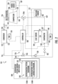
FIG. 2 is a schematic illustration of a refrigeration system, according to an embodiment of the present disclosure; -
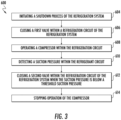
FIG. 3 is a flowchart illustrating a method of shutting down the refrigeration system ofFIG. 2 , according to an embodiment of the present disclosure; and -
FIG. 4 is a flowchart illustrating a method of defrosting the refrigeration system ofFIG. 2 , according to an embodiment of the present disclosure. - A detailed description of one or more embodiments of the invention are presented herein by way of exemplification and not limitation with reference to the Figures.
- Referring to
FIG. 1 , atransport system 420 of the present disclosure is illustrated. In the illustrated embodiment, thetransport systems 420 may include a tractor orvehicle 422, a conditionedspace 112, and arefrigeration system 110. The conditionedspace 112 may be pulled by avehicle 422. It is understood that embodiments described herein may be applied to conditioned space that are shipped by rail, sea, air, or any other suitable container, thus the vehicle may be a truck, train, boat, airplane, helicopter, etc. - The
vehicle 422 may include an operator's compartment orcab 428 and avehicle motor 442. Thevehicle 422 may be driven by a driver located within the cab, driven by a driver remotely, driven autonomously, driven semi-autonomously, or any combination thereof. Thevehicle motor 442 may be an electric or combustion engine powered by a combustible fuel. Thevehicle motor 442 may also be part of the power train or drive system of the trailer system (i.e., conditioned space 112), thus thevehicle motor 442 is configured to propel the wheels of thevehicle 422 and/or the wheels of the conditionedspace 112. Thevehicle motor 442 may be mechanically connected to the wheels of thevehicle 422 and/or the wheels of the conditionedspace 112. - The conditioned
space 112 may be coupled to thevehicle 422 and is thus pulled or propelled to desired destinations. The conditionedspace 112 may include atop wall 430, abottom wall 432 opposed to and spaced from thetop wall 430, twoside walls 434 spaced from and opposed to one-another, and opposing front andrear walls front wall 436 being closest to thevehicle 422. The conditionedspace 112 may further include doors (not shown) at therear wall 438, or any other wall. Thewalls interior volume 114. Typically,transport systems 420 are used to transport and distribute cargo, such as, for example perishable goods and environmentally sensitive goods (herein referred to as perishable goods). The perishable goods may include but are not limited to fruits, vegetables, grains, beans, nuts, eggs, dairy, seed, flowers, meat, poultry, fish, ice, blood, pharmaceuticals, or any other suitable cargo requiring cold chain transport. In the illustrated embodiment, therefrigeration system 110 is associated with a conditionedspace 112 to provide desired environmental parameters, such as, for example temperature, pressure, humidity, carbon dioxide, ethylene, ozone, light exposure, vibration exposure, and other conditions to the refrigeratedinterior volume 114. In further embodiments, therefrigeration system 110 is a refrigeration system capable of providing a desired temperature and humidity range. - Referring to
FIG. 2 , arefrigeration system 110 is illustrated, in accordance with an embodiment of the present disclosure. Arefrigeration system 110 that provides conditioned air or cooled air to aninterior volume 114 of the conditionedspace 112 is illustrated inFIG. 2 . The conditionedspace 112 may include but is not limited to a refrigerated trailer, a refrigerated truck, a refrigerated space, or a refrigerated container. Therefrigeration system 110 may be adapted to operate using a refrigerant such as a low global warming potential refrigerant including A1, A2, A2L, A3, etc. In some case the refrigerant may leak into theinterior volume 114 and may present a hazard should the concentration of the leaked refrigerant within theinterior volume 114 exceed a threshold level. The threshold level may be a lower flammability limit of the refrigerant. Theevaporator 124, a portion of arefrigerant line 169 proximate anevaporator outlet 162, and a portion of arefrigerant line 164 proximate anevaporator inlet 160 may be located within theinterior volume 114 of the conditionedspace 112 and thus may be a potential source of a refrigerant leak into theinterior volume 114. - The
refrigeration system 110 may be a transport refrigeration system such as a transportation refrigeration unit. Therefrigeration system 110 includes acompressor 120, acondenser 122 and anevaporator 124. Therefrigeration system 110 may optionally include aleak detection system 126 that is arranged to detect and mitigate the presence of refrigerant within aninterior volume 114. Embodiments disclosed herein are also applicable torefrigeration systems 110 not including a leak detection system. - The
compressor 120 is powered by or driven by apower source 130. Thepower source 130 may be an internal combustion engine that drives a generator that is arranged to provide power to thecompressor 120 and other components of therefrigeration system 110, or that drives the compressor via belt directly. - The
compressor 120 is arranged to receive refrigerant through acompressor inlet 140 from theevaporator 124. Thecompressor 120 is arranged to discharge refrigerant through acompressor outlet 142 to thecondenser 122. Thecompressor 120 is configured to pump the refrigerant through arefrigerant circuit 116, which is composed of various components including but not limited to arefrigerant line 156, therefrigerant line 164, arefrigerant line 169, afirst valve 166, acheck valve 128, theevaporator 124, thecondenser 122, and asecond valve 176. Therefrigerant line 156, therefrigerant line 164, therefrigerant line 169, thefirst valve 166, thecheck valve 128, theevaporator 124, thecondenser 122, thesecond valve 176, and the compressor are located within therefrigerant circuit 116. Therefrigerant circuit 116 is a closed circuit. - The
condenser 122 is arranged to receive a fluid flow of refrigerant from thecompressor 120 through acondenser inlet 150 and is arranged to discharge a fluid flow of refrigerant through acondenser outlet 152 to theevaporator 124. Thecondenser inlet 150 is fluidly connected to thecompressor outlet 142 through therefrigerant line 156. - An
oil separator 186 may be located within therefrigerant line 156 between thecompressor 120 and thecondenser 122 to remove oil from refrigerant leaving thecompressor outlet 142 and direct the oil back to the suction line of thecompressor 120 or back to body ofcompressor 120. - A fan such as a
condenser fan 158 may be associated with thecondenser 122. Thecondenser fan 158 is disposed proximate thecondenser 122. - The
evaporator 124 is arranged to receive a fluid flow of refrigerant from thecondenser 122 through anevaporator inlet 160 and is arranged to discharge a fluid flow of refrigerant to thecompressor 120 through anevaporator outlet 162. Theevaporator inlet 160 is fluidly connected to thecondenser outlet 152 through arefrigerant line 164. Theevaporator outlet 162 is fluidly connected to thecompressor inlet 140 through arefrigerant line 169. - A fan such as an
evaporator fan 168 may be associated with theevaporator 124. Theevaporator fan 168 is disposed proximate theevaporator 124. - A
first valve 166 is located within therefrigerant line 164 between thecondenser 122 and theevaporator 124. Thefirst valve 166 is arranged to selectively facilitate a fluid flow between thecondenser outlet 152 and theevaporator inlet 160. Thefirst valve 166 may be an expansion valve such as an electronic expansion valve, a movable valve, a solenoid valve, or a thermal expansion valve. Thefirst valve 166 is movable between an open position and a closed position to selectively facilitate and inhibit a fluid flow of refrigerant between theevaporator 124 and thecondenser 122. The open position facilitates a fluid flow of refrigerant between thecondenser outlet 152 and theevaporator inlet 160. The closed position inhibits a fluid flow of refrigerant between thecondenser outlet 152 and theevaporator inlet 160 through therefrigerant line 164. - A
second valve 176 is located within therefrigerant line 156 between thecompressor 120 and thecondenser 122. Thesecond valve 176 is arranged to selectively facilitate a fluid flow between thecompressor outlet 142 and thecondenser inlet 150. Thesecond valve 176 may be a movable valve, a liquid service valve, a thermal expansion valve, or an electronic expansion valve, or a check valve. Thesecond valve 176 is movable between an open position and a closed position. The open position facilitates a fluid flow of refrigerant between thecompressor outlet 142 and thecondenser inlet 150. The closed position inhibits a fluid flow of refrigerant between thecompressor outlet 142 and thecondenser inlet 150 to selectively facilitate a fluid flow between theevaporator outlet 162 and thecompressor inlet 140. - In an embodiment, the
first valve 166 and thesecond valve 176 may be located outside of the conditionedspace 112. - The
refrigeration system 110 may include acheck valve 128 located within therefrigerant line 164 between thefirst valve 166 and theevaporator 124, as shown inFIG. 2 . Therefrigeration system 110 may also include anexpansion valve 184 located within therefrigerant line 164 between thecheck valve 128 and theevaporator 124, as shown inFIG. 2 . Therefrigeration system 110 may additionally include apressure sensor 190 located within therefrigerant line 169 interposed between theevaporator 124 and thecompressor inlet 140. - The
leak detection system 126 comprises aleak sensor 182 and thecontroller 180. Theleak sensor 182 may be configured to detect refrigerant, detect a selected concentration of the refrigerant, and/or calculate a concentration of refrigerant. Theleak sensor 182 may be located within the conditionedspace 112. Thecontroller 180 may be a controller that is provided with the transport refrigeration unit or may be a separately provided controller. - The
controller 180 is provided with input communication channels that are arranged to receive information, data, or signals from, for example, at least one of thecompressor 120, thepower source 130, thecondenser fan 158, thefirst valve 166, theevaporator fan 168, thesecond valve 176, and theleak sensor 182. Thecontroller 180 is provided with output communication channels that are arranged to provide commands, signals, or data, for example, to thecompressor 120, thepower source 130, thecondenser fan 158, thefirst valve 166, theevaporator fan 168, thepressure sensor 190, and thesecond valve 176. Thecontroller 180 is provided with at least one processor that is programmed to execute a leak detection and/or leak mitigation strategy based on information, data, or signals provided via the input communication channels and output commands via the output communication channels. - The
leak sensor 182 is arranged to provide a signal indicative of a concentration, an amount or the presence of refrigerant within theinterior volume 114 to thecontroller 180. Theleak sensor 182 may be disposed proximate theevaporator 124 and/or may be disposed proximate therefrigerant line 169 or any other refrigerant line or component that could leak refrigerant into the conditionedspace 112. Theleak sensor 182 may also be located near a likely location where refrigerant may collect such as near a floor of the conditionedspace 112. - Responsive to the signal from the
leak sensor 182 being indicative of a concentration of refrigerant greater than a threshold concentration or the signal being indicative of the presence of refrigerant within theinterior volume 114, thecontroller 180 may perform leak mitigation as disclosed inU.S. Application No. 62/727,682 filed September 6, 2018 Chinese Application No. 201910312955.3 - The
refrigeration system 110 may also include aheater 148 associated with theevaporator 124. In an embodiment, theheater 148 may be an electric resistance heater. Theheater 148 may be selectively operated by thecontroller 180 whenever a control temperature within the temperature controlled a conditionedspace 112 drops below a preset lower temperature limit, which may occur in a cold ambient environment. In such an event, thecontroller 180 would activate theheater 148 to heat air circulated over theheater 148 by thefan 168 associated with theevaporator 124. Theheater 148 may also be selectively operated by thecontroller 180 to defrost theevaporator 124. For example, theheater 148 may melt ice off of coils of theevaporator 124. - It is to be understood that other components (not shown) may be incorporated into the refrigerant circuit as desired, including for example, but not limited to, a suction modulation valve, a main heat valve, a hot gas valve, a receiver, a filter/dryer, an economizer circuit.
- The
refrigeration system 110 may be in electronic communication with a refrigeration systemcontrol input device 500 that may be located within thecab 428 of thevehicle 422. The refrigeration systemcontrol input device 500 may be an electronic controller including a processor and an associated memory comprising computer-executable instructions that, when executed by the processor, cause the processor to perform various operations. The processor may be, but is not limited to, a single-processor or multi-processor system of any of a wide array of possible architectures, including field programmable gate array (FPGA), central processing unit (CPU), application specific integrated circuits (ASIC), digital signal processor (DSP) or graphics processing unit (GPU) hardware arranged homogenously or heterogeneously. The memory may be but is not limited to a random access memory (RAM), read only memory (ROM), or other electronic, optical, magnetic or any other computer readable medium. - The refrigeration system
control input device 500 may be in wired and/or wireless communication with therefrigeration system 110. The refrigeration systemcontrol input device 500 may be a computing device located in thecab 428 operable to receive input commands from a user and transfer the input commands to thecontroller 180 of therefrigeration system 110. The refrigeration systemcontrol input device 500 may be securely attached to thecab 428 of thevehicle 422, such as, for example, to the dashboard or instrument panel of thevehicle 422. Alternatively, the refrigeration systemcontrol input device 500 may be a handheld or mobile computing device, such as, for example, a smart phone, a laptop, a tablet computer, a smart watch, or similar device known to one of skill in the art. The refrigeration systemcontrol input device 500 may include adisplay device 510 to convey data from therefrigeration system 110 to the user of the refrigeration systemcontrol input device 500. - The refrigeration system
control input device 500 may generate agraphical user interface 540 via thedisplay device 510 for viewing and controlling operation of therefrigeration system 110. The refrigeration systemcontrol input device 500 also includes aninput device 520, such as, example, a mouse, a touch screen, a scroll wheel, a scroll ball, a stylus pen, a microphone, a camera, or similar device known to one of skill in the art. In the example shown inFIG. 2 , thedisplay device 510 is a touchscreen, thus thedisplay device 510 also functions as theinput device 520.FIG. 2 illustrates agraphical user interface 540 that may be generated on thedisplay device 510 of the refrigeration systemcontrol input device 500. A user may interact with thegraphical user interface 540 through a selection input, such as, for example, a "click", "touch", verbal command, gesture recognition, or any other input to thegraphical user interface 540. The "click" or touch" may be via the input device 630. - The
graphical user interface 540 may displaycontrol icons control icons refrigeration system 110, thus when a user selects acontrol icon refrigeration system 110 may be prompted to perform that action associated with the control icon selected. The selection input may be received at or on thecontrol icon - The
control icon 550A may be associated with a shutdown of therefrigeration system 110 and thus the text "REFRIGERATION SYSTEM SHUTDOWN" may be displayed on thecontrol icon 550A. When a user selects thecontrol icon 550A via a selection input using theinput device 520 then a command is sent to thecontroller 180 and thecontroller 180 will initiate a shutdown process of therefrigeration system 110, as discussed further inmethod 600 herein. It is understood that the embodiments disclosed herein are also applicable to automatic shutdown of therefrigeration system 110 without the need for a selection input. - The
control icon 550B may be associated with a defrost of therefrigeration system 110 and thus the text "REFRIGERATION SYSTEM DEFROST ACTIVATION" may be displayed on thecontrol icon 550B. When a user selects thecontrol icon 550B via a selection input using theinput device 520 then a command is sent to thecontroller 180 and thecontroller 180 will initiate a defrost process of therefrigeration system 110, as discussed further inmethod 700 herein. It is understood that the embodiments disclosed herein are also applicable to automatic defrost of therefrigeration system 110 without the need for a selection input. - Referring to
FIG. 3 , with continued reference toFIGS. 1 and2 , amethod 600 of shutting down therefrigeration system 110 is illustrated in accordance with an embodiment of the present disclosure. In an embodiment, themethod 600 may be performed by thecontroller 180 and/or the refrigeration systemcontrol input device 500. - At
block 604, the shutdown process of therefrigeration system 110 is initiated. The shutdown process of therefrigeration system 110 may be initiated automatically or when a selection input is received from a user of a refrigeration systemcontrol input device 500 indicating that the user desires to initiate a shutdown process of therefrigeration system 110.Block 604 may include that agraphical user interface 540 is generated on adisplay device 510 of the refrigeration systemcontrol input device 500 and acontrol icon 550A representing initiation of the shutdown process is displayed. The selection input is received at thecontrol icon 550A. - At block 606 a
first valve 166 within arefrigerant circuit 116 of therefrigeration system 110 is closed. Thefirst valve 166 is located within therefrigerant circuit 116 between thecondenser 122 and theevaporator 124. Thus, closing thefirst valve 166 stops flow of refrigerant from thecondenser 122 to theevaporator 124. In an embodiment, thefirst valve 166 is located outside of a conditionedspace 112 of therefrigeration system 110. - At
block 608, acompressor 120 within therefrigerant circuit 116 is operated. At block 610 a suction pressure within therefrigerant circuit 116 is detected. In an embodiment, the suction pressure is detected proximate acompressor 120 inlet of thecompressor 120. - At
block 612, asecond valve 176 within therefrigerant circuit 116 of therefrigeration system 110 is closed when the suction pressure is below a threshold suction pressure. Closing thefirst valve 166 and thesecond valve 176 maintains the suction pressure below the threshold suction pressure. Thesecond valve 176 is located within therefrigerant circuit 116 between thecompressor 120 and thecondenser 122. Thus, closing thesecond valve 176 stops flow of refrigerant from thecompressor 120 to thecondenser 122. In an embodiment, thesecond valve 176 is located outside of a conditionedspace 112 of therefrigeration system 110. The threshold suction pressure may be indicative that the refrigerant has been evacuated from therefrigerant circuit 116 betweenfirst valve 166 and thesecond valve 176. In other words, the threshold suction pressure may be indicative that the refrigerant has been evacuated from therefrigerant line 164 between thefirst valve 166 and theevaporator 124, theevaporator 124, therefrigerant line 169, thecompressor 120, and therefrigerant line 156 between the compressor and thesecond valve 176. - At
block 614, operation of thecompressor 120 is stopped. Themethod 600 may also include stop operations of therefrigeration system 110. - While the above description has described the flow process of
FIG. 3 in a particular order, it should be appreciated that unless otherwise specifically required in the attached claims that the ordering of the steps may be varied. - Referring to
FIG. 4 , with continued reference toFIGS. 1 and2 , amethod 700 of defrosting therefrigeration system 110 is illustrated in accordance with an embodiment of the present disclosure. In an embodiment, themethod 700 may be performed by thecontroller 180 and/or the refrigeration systemcontrol input device 500. - At
block 704, the defrost process of therefrigeration system 110 is initiated. The defrost process of therefrigeration system 110 may be initiated automatically or when a selection input is received from a user of a refrigeration systemcontrol input device 500 indicating that the user desires to initiate a defrost process of therefrigeration system 110.Block 704 may include that agraphical user interface 540 is generated on adisplay device 510 of the refrigeration systemcontrol input device 500 and acontrol icon 550B representing initiation of the defrost process is displayed. The selection input is received at thecontrol icon 550B. - At
block 706, afirst valve 166 within arefrigerant circuit 116 of therefrigeration system 110 is closed. Thefirst valve 166 is located within therefrigerant circuit 116 between thecondenser 122 and theevaporator 124. Thus, closing thefirst valve 166 stops flow of refrigerant from thecondenser 122 to theevaporator 124. In an embodiment, thefirst valve 166 is located outside of a conditionedspace 112 of therefrigeration system 110. - At
block 708, acompressor 120 within therefrigerant circuit 116 is operated. Atblock 710, a suction pressure within therefrigerant circuit 116 is detected. In an embodiment, the suction pressure is detected proximate acompressor 120 inlet of thecompressor 120. - At
block 712, asecond valve 176 within therefrigerant circuit 116 of therefrigeration system 110 is closed when the suction pressure is below a threshold suction pressure. Closing thefirst valve 166 and thesecond valve 176 maintains the suction pressure below the threshold suction pressure. Thesecond valve 176 is located within therefrigerant circuit 116 between thecompressor 120 and thecondenser 122. Thus, closing thesecond valve 176 stops flow of refrigerant from thecompressor 120 to thecondenser 122. In an embodiment, thesecond valve 176 is located outside of a conditionedspace 112 of therefrigeration system 110. The threshold suction pressure may be indicative that the refrigerant has been evacuated from therefrigerant circuit 116 betweenfirst valve 166 and thesecond valve 176. In other words, the threshold suction pressure may be indicative that the refrigerant has been evacuated from therefrigerant line 164 between thefirst valve 166 and theevaporator 124, theevaporator 124, therefrigerant line 169, thecompressor 120, and therefrigerant line 156 between the compressor and thesecond valve 176. - At
block 714, operation of thecompressor 120 is stopped. Atblock 716, the defrost process of therefrigeration system 110 is initiated. Themethod 700 may further comprise that aheater 148 of therefrigeration system 110 is activated to prevent heating the refrigerant of therefrigeration system 110 during the defrost process. Theheater 148 may be located proximate anevaporator 124 of therefrigeration system 110. - While the above description has described the flow process of
FIG. 4 in a particular order, it should be appreciated that unless otherwise specifically required in the attached claims that the ordering of the steps may be varied. - The term "about" is intended to include the degree of error associated with measurement of the particular quantity based upon the equipment available at the time of filing the application.
- The terminology used herein is for the purpose of describing particular embodiments only is not intended to be limiting of the present disclosure. As used herein, the singular forms "a", "an" and "the" are intended to include the plural forms as well, unless the context clearly indicates otherwise. It will be further understood that the terms "comprises" and/or "comprising," when used in this specification, specify the presence of stated features, integers, steps, operations, elements, and/or components, but do not preclude the presence or addition of one or more other features, integers, steps, operations, element components, and/or groups thereof.
- While the present disclosure has been described with reference to an exemplary embodiment or embodiments, it will be understood by those skilled in the art that various changes may be made and equivalents may be substituted for elements thereof without departing from the scope of the present disclosure. In addition, many modifications may be made to adapt a particular situation or material to the teachings of the present disclosure without departing from the essential scope thereof. Therefore, it is intended that the present disclosure not be limited to the particular embodiment disclosed as the best mode contemplated for carrying out this present disclosure, but that the present invention will include all embodiments falling within the scope of the claims.
Claims (9)
- A method (600) of shutting down or defrosting within a refrigeration system (110), comprising:initiating a shutdown process or a defrost process of the refrigeration system;closing a first valve (166) within a refrigerant circuit (116) of the refrigeration system, wherein the first valve is located within the refrigerant circuit between a condenser (122) and an evaporator (124), and wherein closing the first valve stops flow of refrigerant from the condenser to the evaporator;operating a compressor (120) within the refrigerant circuit;detecting a suction pressure within the refrigerant circuit;closing a second valve (176) within the refrigerant circuit of the refrigeration system when the suction pressure is below a threshold suction pressure, wherein the second valve is located within the refrigerant circuit between the compressor and the condenser (122), and wherein closing the second valve stops flow of refrigerant from the compressor to the condenser; andstopping operation of the compressor.
- The method of claim 1, further comprising:
receiving a selection input from a user of a refrigeration system control input device (500) indicating that the user desires to initiate the shutdown process or defrost process of the refrigeration system (110). - The method of claim 2, further comprising:generating a graphical user interface (540) on a display device (510) of the refrigeration system control input device (500); anddisplaying a control icon (550A) representing initiation of the shutdown process or defrost process,wherein the selection input is received at the control icon.
- The method of claim 1, wherein the method is a method of shutting down the refrigeration system, wherein the method comprises initiating the shutdown process of the refrigeration system, and wherein the method further comprises:
stopping operation of the refrigeration system (110). - The method of claim 1, wherein the suction pressure is detected proximate a compressor inlet of the compressor (120).
- The method of claim 1, wherein the first valve (166) is located outside of a conditioned space (112) of the refrigeration system (110).
- The method of claim 1, wherein closing the first valve (166) and the second valve (176) maintains the suction pressure below the threshold suction pressure.
- The method of claim 1, wherein the method is a method of defrosting within the refrigeration system, wherein the method comprises initiating the defrost process of the refrigeration system, and wherein the method further comprises:
activating a heater (148) of the refrigeration system. - The method of claim 8, wherein the heater is located proximate the evaporator (124) of the refrigeration system (110).
Applications Claiming Priority (3)
| Application Number | Priority Date | Filing Date | Title |
|---|---|---|---|
| CN201910312955 | 2019-04-18 | ||
| CN201910841812.1A CN111829218B (en) | 2019-04-18 | 2019-09-06 | Refrigerant system operating sequence for leak prevention |
| PCT/US2020/049034 WO2021046107A1 (en) | 2019-04-18 | 2020-09-02 | Refrigerant system operation sequences for leak prevention |
Publications (2)
| Publication Number | Publication Date |
|---|---|
| EP4025848A1 EP4025848A1 (en) | 2022-07-13 |
| EP4025848B1 true EP4025848B1 (en) | 2024-12-04 |
Family
ID=72912550
Family Applications (1)
| Application Number | Title | Priority Date | Filing Date |
|---|---|---|---|
| EP20775115.7A Active EP4025848B1 (en) | 2019-04-18 | 2020-09-02 | Refrigerant system operation sequences for leak prevention |
Country Status (4)
| Country | Link |
|---|---|
| US (1) | US11885543B2 (en) |
| EP (1) | EP4025848B1 (en) |
| CN (1) | CN111829218B (en) |
| WO (1) | WO2021046107A1 (en) |
Families Citing this family (5)
| Publication number | Priority date | Publication date | Assignee | Title |
|---|---|---|---|---|
| US11614091B2 (en) | 2020-06-30 | 2023-03-28 | Thermo King Llc | Systems and methods for protecting sealed compressor electrical feedthrough |
| US11554640B2 (en) | 2020-06-30 | 2023-01-17 | Thermo King Llc | Isolated evaporator coil for a transport climate control system |
| US11674726B2 (en) | 2020-06-30 | 2023-06-13 | Thermo King Llc | Systems and methods for transport climate control circuit management and isolation |
| US11565575B2 (en) | 2020-06-30 | 2023-01-31 | Thermo King Llc | Air management system for climate control unit of a transport climate control system |
| US11738623B2 (en) | 2021-03-31 | 2023-08-29 | Thermo King Llc | Transport climate control remote management |
Family Cites Families (8)
| Publication number | Priority date | Publication date | Assignee | Title |
|---|---|---|---|---|
| US7886550B2 (en) * | 2005-05-06 | 2011-02-15 | Panasonic Corporation | Refrigerating machine |
| KR20120012613A (en) | 2010-08-02 | 2012-02-10 | 삼성전자주식회사 | Refrigerator and its control method |
| US10501972B2 (en) * | 2015-03-31 | 2019-12-10 | Follett Corporation | Refrigeration system and control system therefor |
| CN108027185B (en) * | 2015-10-27 | 2020-06-05 | 株式会社电装 | Refrigeration cycle device |
| US20180187969A1 (en) * | 2017-01-03 | 2018-07-05 | Samsung Electronics Co., Ltd. | Refrigerator |
| EP3598037B1 (en) | 2017-03-13 | 2024-02-21 | Mitsubishi Electric Corporation | Refrigeration cycle device |
| CN110709650B (en) * | 2017-06-09 | 2021-10-15 | 三菱电机株式会社 | Heat pump utilization equipment |
| US12140334B2 (en) * | 2020-03-27 | 2024-11-12 | Tyco Fire & Security Gmbh | Systems and methods for communication in HVAC system |
-
2019
- 2019-09-06 CN CN201910841812.1A patent/CN111829218B/en active Active
-
2020
- 2020-09-02 US US15/734,219 patent/US11885543B2/en active Active
- 2020-09-02 WO PCT/US2020/049034 patent/WO2021046107A1/en not_active Ceased
- 2020-09-02 EP EP20775115.7A patent/EP4025848B1/en active Active
Also Published As
| Publication number | Publication date |
|---|---|
| EP4025848A1 (en) | 2022-07-13 |
| US11885543B2 (en) | 2024-01-30 |
| US20220196304A1 (en) | 2022-06-23 |
| WO2021046107A1 (en) | 2021-03-11 |
| CN111829218B (en) | 2024-12-06 |
| CN111829218A (en) | 2020-10-27 |
Similar Documents
| Publication | Publication Date | Title |
|---|---|---|
| US11885543B2 (en) | Refrigerant system operation sequences for leak prevention | |
| US11441820B2 (en) | Refrigerant leak detection system | |
| US11472265B2 (en) | Refrigerant leak detection system | |
| CN102328568B (en) | Electric transport refrigeration unit with temperature-based diesel operation | |
| EP3472542B1 (en) | Transport refrigeration system with a battery system and corresponding method | |
| EP3833914B1 (en) | Heated gas detector for a transportation refrigeration unit | |
| US6910341B2 (en) | Temperature control apparatus and method of operating the same | |
| CN109311389B (en) | Single point filling for self-contained refrigeration units driven by separate engines | |
| US11117449B2 (en) | Fuel system control for refrigeration unit engine | |
| US12138985B2 (en) | Trailer compartment transportation refrigeration unit operation visualization | |
| EP3669063B1 (en) | Natural gas tank pressure control for transport refrigeration unit | |
| CN113858907A (en) | System and method for management and isolation of transport climate control circuits | |
| EP3465102B1 (en) | Method for determining reduced airflow in transport refrigeration system | |
| US20210254881A1 (en) | Defrost system and method of defrosting an evaporator section of a temperature control unit | |
| EP4137761A2 (en) | Transport refrigeration unit and method of operating a transport refrigeration unit | |
| EP3833572B1 (en) | Crash detection system for transport refrigeration units |
Legal Events
| Date | Code | Title | Description |
|---|---|---|---|
| STAA | Information on the status of an ep patent application or granted ep patent |
Free format text: STATUS: UNKNOWN |
|
| STAA | Information on the status of an ep patent application or granted ep patent |
Free format text: STATUS: THE INTERNATIONAL PUBLICATION HAS BEEN MADE |
|
| PUAI | Public reference made under article 153(3) epc to a published international application that has entered the european phase |
Free format text: ORIGINAL CODE: 0009012 |
|
| STAA | Information on the status of an ep patent application or granted ep patent |
Free format text: STATUS: REQUEST FOR EXAMINATION WAS MADE |
|
| 17P | Request for examination filed |
Effective date: 20210125 |
|
| AK | Designated contracting states |
Kind code of ref document: A1 Designated state(s): AL AT BE BG CH CY CZ DE DK EE ES FI FR GB GR HR HU IE IS IT LI LT LU LV MC MK MT NL NO PL PT RO RS SE SI SK SM TR |
|
| DAV | Request for validation of the european patent (deleted) | ||
| DAX | Request for extension of the european patent (deleted) | ||
| GRAP | Despatch of communication of intention to grant a patent |
Free format text: ORIGINAL CODE: EPIDOSNIGR1 |
|
| STAA | Information on the status of an ep patent application or granted ep patent |
Free format text: STATUS: GRANT OF PATENT IS INTENDED |
|
| INTG | Intention to grant announced |
Effective date: 20240705 |
|
| GRAS | Grant fee paid |
Free format text: ORIGINAL CODE: EPIDOSNIGR3 |
|
| GRAA | (expected) grant |
Free format text: ORIGINAL CODE: 0009210 |
|
| STAA | Information on the status of an ep patent application or granted ep patent |
Free format text: STATUS: THE PATENT HAS BEEN GRANTED |
|
| AK | Designated contracting states |
Kind code of ref document: B1 Designated state(s): AL AT BE BG CH CY CZ DE DK EE ES FI FR GB GR HR HU IE IS IT LI LT LU LV MC MK MT NL NO PL PT RO RS SE SI SK SM TR |
|
| REG | Reference to a national code |
Ref country code: CH Ref legal event code: EP |
|
| REG | Reference to a national code |
Ref country code: NL Ref legal event code: FP |
|
| REG | Reference to a national code |
Ref country code: DE Ref legal event code: R096 Ref document number: 602020042559 Country of ref document: DE |
|
| REG | Reference to a national code |
Ref country code: IE Ref legal event code: FG4D |
|
| REG | Reference to a national code |
Ref country code: LT Ref legal event code: MG9D |
|
| PG25 | Lapsed in a contracting state [announced via postgrant information from national office to epo] |
Ref country code: HR Free format text: LAPSE BECAUSE OF FAILURE TO SUBMIT A TRANSLATION OF THE DESCRIPTION OR TO PAY THE FEE WITHIN THE PRESCRIBED TIME-LIMIT Effective date: 20241204 |
|
| PG25 | Lapsed in a contracting state [announced via postgrant information from national office to epo] |
Ref country code: FI Free format text: LAPSE BECAUSE OF FAILURE TO SUBMIT A TRANSLATION OF THE DESCRIPTION OR TO PAY THE FEE WITHIN THE PRESCRIBED TIME-LIMIT Effective date: 20241204 |
|
| PG25 | Lapsed in a contracting state [announced via postgrant information from national office to epo] |
Ref country code: BG Free format text: LAPSE BECAUSE OF FAILURE TO SUBMIT A TRANSLATION OF THE DESCRIPTION OR TO PAY THE FEE WITHIN THE PRESCRIBED TIME-LIMIT Effective date: 20241204 |
|
| PG25 | Lapsed in a contracting state [announced via postgrant information from national office to epo] |
Ref country code: ES Free format text: LAPSE BECAUSE OF FAILURE TO SUBMIT A TRANSLATION OF THE DESCRIPTION OR TO PAY THE FEE WITHIN THE PRESCRIBED TIME-LIMIT Effective date: 20241204 |
|
| PG25 | Lapsed in a contracting state [announced via postgrant information from national office to epo] |
Ref country code: NO Free format text: LAPSE BECAUSE OF FAILURE TO SUBMIT A TRANSLATION OF THE DESCRIPTION OR TO PAY THE FEE WITHIN THE PRESCRIBED TIME-LIMIT Effective date: 20250304 |
|
| PG25 | Lapsed in a contracting state [announced via postgrant information from national office to epo] |
Ref country code: GR Free format text: LAPSE BECAUSE OF FAILURE TO SUBMIT A TRANSLATION OF THE DESCRIPTION OR TO PAY THE FEE WITHIN THE PRESCRIBED TIME-LIMIT Effective date: 20250305 Ref country code: LV Free format text: LAPSE BECAUSE OF FAILURE TO SUBMIT A TRANSLATION OF THE DESCRIPTION OR TO PAY THE FEE WITHIN THE PRESCRIBED TIME-LIMIT Effective date: 20241204 |
|
| PG25 | Lapsed in a contracting state [announced via postgrant information from national office to epo] |
Ref country code: RS Free format text: LAPSE BECAUSE OF FAILURE TO SUBMIT A TRANSLATION OF THE DESCRIPTION OR TO PAY THE FEE WITHIN THE PRESCRIBED TIME-LIMIT Effective date: 20250304 |
|
| REG | Reference to a national code |
Ref country code: AT Ref legal event code: MK05 Ref document number: 1748568 Country of ref document: AT Kind code of ref document: T Effective date: 20241204 |
|
| PG25 | Lapsed in a contracting state [announced via postgrant information from national office to epo] |
Ref country code: SM Free format text: LAPSE BECAUSE OF FAILURE TO SUBMIT A TRANSLATION OF THE DESCRIPTION OR TO PAY THE FEE WITHIN THE PRESCRIBED TIME-LIMIT Effective date: 20241204 |
|
| PG25 | Lapsed in a contracting state [announced via postgrant information from national office to epo] |
Ref country code: PL Free format text: LAPSE BECAUSE OF FAILURE TO SUBMIT A TRANSLATION OF THE DESCRIPTION OR TO PAY THE FEE WITHIN THE PRESCRIBED TIME-LIMIT Effective date: 20241204 |
|
| PG25 | Lapsed in a contracting state [announced via postgrant information from national office to epo] |
Ref country code: IS Free format text: LAPSE BECAUSE OF FAILURE TO SUBMIT A TRANSLATION OF THE DESCRIPTION OR TO PAY THE FEE WITHIN THE PRESCRIBED TIME-LIMIT Effective date: 20250404 |
|
| PG25 | Lapsed in a contracting state [announced via postgrant information from national office to epo] |
Ref country code: PT Free format text: LAPSE BECAUSE OF FAILURE TO SUBMIT A TRANSLATION OF THE DESCRIPTION OR TO PAY THE FEE WITHIN THE PRESCRIBED TIME-LIMIT Effective date: 20250404 |
|
| PG25 | Lapsed in a contracting state [announced via postgrant information from national office to epo] |
Ref country code: EE Free format text: LAPSE BECAUSE OF FAILURE TO SUBMIT A TRANSLATION OF THE DESCRIPTION OR TO PAY THE FEE WITHIN THE PRESCRIBED TIME-LIMIT Effective date: 20241204 |
|
| PG25 | Lapsed in a contracting state [announced via postgrant information from national office to epo] |
Ref country code: AT Free format text: LAPSE BECAUSE OF FAILURE TO SUBMIT A TRANSLATION OF THE DESCRIPTION OR TO PAY THE FEE WITHIN THE PRESCRIBED TIME-LIMIT Effective date: 20241204 Ref country code: RO Free format text: LAPSE BECAUSE OF FAILURE TO SUBMIT A TRANSLATION OF THE DESCRIPTION OR TO PAY THE FEE WITHIN THE PRESCRIBED TIME-LIMIT Effective date: 20241204 |
|
| PG25 | Lapsed in a contracting state [announced via postgrant information from national office to epo] |
Ref country code: SK Free format text: LAPSE BECAUSE OF FAILURE TO SUBMIT A TRANSLATION OF THE DESCRIPTION OR TO PAY THE FEE WITHIN THE PRESCRIBED TIME-LIMIT Effective date: 20241204 |
|
| PG25 | Lapsed in a contracting state [announced via postgrant information from national office to epo] |
Ref country code: CZ Free format text: LAPSE BECAUSE OF FAILURE TO SUBMIT A TRANSLATION OF THE DESCRIPTION OR TO PAY THE FEE WITHIN THE PRESCRIBED TIME-LIMIT Effective date: 20241204 |
|
| PG25 | Lapsed in a contracting state [announced via postgrant information from national office to epo] |
Ref country code: IT Free format text: LAPSE BECAUSE OF FAILURE TO SUBMIT A TRANSLATION OF THE DESCRIPTION OR TO PAY THE FEE WITHIN THE PRESCRIBED TIME-LIMIT Effective date: 20241204 |
|
| REG | Reference to a national code |
Ref country code: DE Ref legal event code: R097 Ref document number: 602020042559 Country of ref document: DE |
|
| PG25 | Lapsed in a contracting state [announced via postgrant information from national office to epo] |
Ref country code: SE Free format text: LAPSE BECAUSE OF FAILURE TO SUBMIT A TRANSLATION OF THE DESCRIPTION OR TO PAY THE FEE WITHIN THE PRESCRIBED TIME-LIMIT Effective date: 20241204 |
|
| PG25 | Lapsed in a contracting state [announced via postgrant information from national office to epo] |
Ref country code: DK Free format text: LAPSE BECAUSE OF FAILURE TO SUBMIT A TRANSLATION OF THE DESCRIPTION OR TO PAY THE FEE WITHIN THE PRESCRIBED TIME-LIMIT Effective date: 20241204 |
|
| PGFP | Annual fee paid to national office [announced via postgrant information from national office to epo] |
Ref country code: DE Payment date: 20250820 Year of fee payment: 6 |
|
| PLBE | No opposition filed within time limit |
Free format text: ORIGINAL CODE: 0009261 |
|
| STAA | Information on the status of an ep patent application or granted ep patent |
Free format text: STATUS: NO OPPOSITION FILED WITHIN TIME LIMIT |
|
| REG | Reference to a national code |
Ref country code: CH Ref legal event code: L10 Free format text: ST27 STATUS EVENT CODE: U-0-0-L10-L00 (AS PROVIDED BY THE NATIONAL OFFICE) Effective date: 20251015 |
|
| PGFP | Annual fee paid to national office [announced via postgrant information from national office to epo] |
Ref country code: GB Payment date: 20250820 Year of fee payment: 6 |
|
| PGFP | Annual fee paid to national office [announced via postgrant information from national office to epo] |
Ref country code: FR Payment date: 20250820 Year of fee payment: 6 |
|
| 26N | No opposition filed |
Effective date: 20250905 |
|
| REG | Reference to a national code |
Ref country code: CH Ref legal event code: H13 Free format text: ST27 STATUS EVENT CODE: U-0-0-H10-H13 (AS PROVIDED BY THE NATIONAL OFFICE) Effective date: 20260425 |
|
| REG | Reference to a national code |
Ref country code: NL Ref legal event code: MM Effective date: 20251001 |