EP4025347B1 - Magnetic filter - Google Patents
Magnetic filter Download PDFInfo
- Publication number
- EP4025347B1 EP4025347B1 EP20742491.2A EP20742491A EP4025347B1 EP 4025347 B1 EP4025347 B1 EP 4025347B1 EP 20742491 A EP20742491 A EP 20742491A EP 4025347 B1 EP4025347 B1 EP 4025347B1
- Authority
- EP
- European Patent Office
- Prior art keywords
- magnet
- site
- separator
- fuel
- filter
- Prior art date
- Legal status (The legal status is an assumption and is not a legal conclusion. Google has not performed a legal analysis and makes no representation as to the accuracy of the status listed.)
- Active
Links
Images


Classifications
-
- B—PERFORMING OPERATIONS; TRANSPORTING
- B03—SEPARATION OF SOLID MATERIALS USING LIQUIDS OR USING PNEUMATIC TABLES OR JIGS; MAGNETIC OR ELECTROSTATIC SEPARATION OF SOLID MATERIALS FROM SOLID MATERIALS OR FLUIDS; SEPARATION BY HIGH-VOLTAGE ELECTRIC FIELDS
- B03C—MAGNETIC OR ELECTROSTATIC SEPARATION OF SOLID MATERIALS FROM SOLID MATERIALS OR FLUIDS; SEPARATION BY HIGH-VOLTAGE ELECTRIC FIELDS
- B03C1/00—Magnetic separation
- B03C1/02—Magnetic separation acting directly on the substance being separated
- B03C1/025—High gradient magnetic separators
- B03C1/031—Component parts; Auxiliary operations
- B03C1/033—Component parts; Auxiliary operations characterised by the magnetic circuit
- B03C1/0332—Component parts; Auxiliary operations characterised by the magnetic circuit using permanent magnets
-
- B—PERFORMING OPERATIONS; TRANSPORTING
- B01—PHYSICAL OR CHEMICAL PROCESSES OR APPARATUS IN GENERAL
- B01D—SEPARATION
- B01D35/00—Filtering devices having features not specifically covered by groups B01D24/00 - B01D33/00, or for applications not specifically covered by groups B01D24/00 - B01D33/00; Auxiliary devices for filtration; Filter housing constructions
- B01D35/06—Filters making use of electricity or magnetism
-
- B—PERFORMING OPERATIONS; TRANSPORTING
- B03—SEPARATION OF SOLID MATERIALS USING LIQUIDS OR USING PNEUMATIC TABLES OR JIGS; MAGNETIC OR ELECTROSTATIC SEPARATION OF SOLID MATERIALS FROM SOLID MATERIALS OR FLUIDS; SEPARATION BY HIGH-VOLTAGE ELECTRIC FIELDS
- B03C—MAGNETIC OR ELECTROSTATIC SEPARATION OF SOLID MATERIALS FROM SOLID MATERIALS OR FLUIDS; SEPARATION BY HIGH-VOLTAGE ELECTRIC FIELDS
- B03C1/00—Magnetic separation
- B03C1/02—Magnetic separation acting directly on the substance being separated
- B03C1/035—Open gradient magnetic separators, i.e. separators in which the gap is unobstructed, characterised by the configuration of the gap
-
- B—PERFORMING OPERATIONS; TRANSPORTING
- B03—SEPARATION OF SOLID MATERIALS USING LIQUIDS OR USING PNEUMATIC TABLES OR JIGS; MAGNETIC OR ELECTROSTATIC SEPARATION OF SOLID MATERIALS FROM SOLID MATERIALS OR FLUIDS; SEPARATION BY HIGH-VOLTAGE ELECTRIC FIELDS
- B03C—MAGNETIC OR ELECTROSTATIC SEPARATION OF SOLID MATERIALS FROM SOLID MATERIALS OR FLUIDS; SEPARATION BY HIGH-VOLTAGE ELECTRIC FIELDS
- B03C1/00—Magnetic separation
- B03C1/02—Magnetic separation acting directly on the substance being separated
- B03C1/28—Magnetic plugs and dipsticks
- B03C1/286—Magnetic plugs and dipsticks disposed at the inner circumference of a recipient, e.g. magnetic drain bolt
-
- B—PERFORMING OPERATIONS; TRANSPORTING
- B04—CENTRIFUGAL APPARATUS OR MACHINES FOR CARRYING-OUT PHYSICAL OR CHEMICAL PROCESSES
- B04C—APPARATUS USING FREE VORTEX FLOW, e.g. CYCLONES
- B04C3/00—Apparatus in which the axial direction of the vortex flow following a screw-thread type line remains unchanged ; Devices in which one of the two discharge ducts returns centrally through the vortex chamber, a reverse-flow vortex being prevented by bulkheads in the central discharge duct
-
- F—MECHANICAL ENGINEERING; LIGHTING; HEATING; WEAPONS; BLASTING
- F02—COMBUSTION ENGINES; HOT-GAS OR COMBUSTION-PRODUCT ENGINE PLANTS
- F02M—SUPPLYING COMBUSTION ENGINES IN GENERAL WITH COMBUSTIBLE MIXTURES OR CONSTITUENTS THEREOF
- F02M37/00—Apparatus or systems for feeding liquid fuel from storage containers to carburettors or fuel-injection apparatus; Arrangements for purifying liquid fuel specially adapted for, or arranged on, internal-combustion engines
- F02M37/22—Arrangements for purifying liquid fuel specially adapted for, or arranged on, internal-combustion engines, e.g. arrangements in the feeding system
- F02M37/32—Arrangements for purifying liquid fuel specially adapted for, or arranged on, internal-combustion engines, e.g. arrangements in the feeding system characterised by filters or filter arrangements
-
- F—MECHANICAL ENGINEERING; LIGHTING; HEATING; WEAPONS; BLASTING
- F02—COMBUSTION ENGINES; HOT-GAS OR COMBUSTION-PRODUCT ENGINE PLANTS
- F02M—SUPPLYING COMBUSTION ENGINES IN GENERAL WITH COMBUSTIBLE MIXTURES OR CONSTITUENTS THEREOF
- F02M37/00—Apparatus or systems for feeding liquid fuel from storage containers to carburettors or fuel-injection apparatus; Arrangements for purifying liquid fuel specially adapted for, or arranged on, internal-combustion engines
- F02M37/22—Arrangements for purifying liquid fuel specially adapted for, or arranged on, internal-combustion engines, e.g. arrangements in the feeding system
- F02M37/32—Arrangements for purifying liquid fuel specially adapted for, or arranged on, internal-combustion engines, e.g. arrangements in the feeding system characterised by filters or filter arrangements
- F02M37/34—Arrangements for purifying liquid fuel specially adapted for, or arranged on, internal-combustion engines, e.g. arrangements in the feeding system characterised by filters or filter arrangements by the filter structure, e.g. honeycomb, mesh or fibrous
-
- F—MECHANICAL ENGINEERING; LIGHTING; HEATING; WEAPONS; BLASTING
- F02—COMBUSTION ENGINES; HOT-GAS OR COMBUSTION-PRODUCT ENGINE PLANTS
- F02M—SUPPLYING COMBUSTION ENGINES IN GENERAL WITH COMBUSTIBLE MIXTURES OR CONSTITUENTS THEREOF
- F02M37/00—Apparatus or systems for feeding liquid fuel from storage containers to carburettors or fuel-injection apparatus; Arrangements for purifying liquid fuel specially adapted for, or arranged on, internal-combustion engines
- F02M37/22—Arrangements for purifying liquid fuel specially adapted for, or arranged on, internal-combustion engines, e.g. arrangements in the feeding system
- F02M37/32—Arrangements for purifying liquid fuel specially adapted for, or arranged on, internal-combustion engines, e.g. arrangements in the feeding system characterised by filters or filter arrangements
- F02M37/52—Arrangements for purifying liquid fuel specially adapted for, or arranged on, internal-combustion engines, e.g. arrangements in the feeding system characterised by filters or filter arrangements using magnetic means
-
- B—PERFORMING OPERATIONS; TRANSPORTING
- B03—SEPARATION OF SOLID MATERIALS USING LIQUIDS OR USING PNEUMATIC TABLES OR JIGS; MAGNETIC OR ELECTROSTATIC SEPARATION OF SOLID MATERIALS FROM SOLID MATERIALS OR FLUIDS; SEPARATION BY HIGH-VOLTAGE ELECTRIC FIELDS
- B03C—MAGNETIC OR ELECTROSTATIC SEPARATION OF SOLID MATERIALS FROM SOLID MATERIALS OR FLUIDS; SEPARATION BY HIGH-VOLTAGE ELECTRIC FIELDS
- B03C2201/00—Details of magnetic or electrostatic separation
- B03C2201/18—Magnetic separation whereby the particles are suspended in a liquid
-
- B—PERFORMING OPERATIONS; TRANSPORTING
- B03—SEPARATION OF SOLID MATERIALS USING LIQUIDS OR USING PNEUMATIC TABLES OR JIGS; MAGNETIC OR ELECTROSTATIC SEPARATION OF SOLID MATERIALS FROM SOLID MATERIALS OR FLUIDS; SEPARATION BY HIGH-VOLTAGE ELECTRIC FIELDS
- B03C—MAGNETIC OR ELECTROSTATIC SEPARATION OF SOLID MATERIALS FROM SOLID MATERIALS OR FLUIDS; SEPARATION BY HIGH-VOLTAGE ELECTRIC FIELDS
- B03C2201/00—Details of magnetic or electrostatic separation
- B03C2201/30—Details of magnetic or electrostatic separation for use in or with vehicles
-
- B—PERFORMING OPERATIONS; TRANSPORTING
- B04—CENTRIFUGAL APPARATUS OR MACHINES FOR CARRYING-OUT PHYSICAL OR CHEMICAL PROCESSES
- B04C—APPARATUS USING FREE VORTEX FLOW, e.g. CYCLONES
- B04C9/00—Combinations with other devices, e.g. fans, expansion chambers, diffusors, water locks
- B04C2009/004—Combinations with other devices, e.g. fans, expansion chambers, diffusors, water locks with internal filters, in the cyclone chamber or in the vortex finder
Definitions
- the invention concerns a magnetic filter for fuel and hydraulic systems to remove metallic impurities, in particular shavings, to be used in fuel systems in the automotive industry on common-rail systems and in hydraulic systems to the full extent of their industrial application.
- a majority of closed circuits filled with liquid are fitted with a mechanical or otherwise active filter through which the liquid flows and by which undesirable substances that could damage other components of the closed circuit are eliminated.
- Shavings can be generated, for example, in the fuel system of Diesel vehicles due to low-quality Diesel oil which then poorly lubricates the fuel feed pump in the fuel tank, which results in high friction.
- the fuel feed pump starts producing invisible metallic shavings which then wear the highpressure pump that will start generating other metallic particles as well.
- Such tiny metallic particles go through the fuel filter due to their miniature size and enter fuel injectors that will thus become irreversibly damaged.
- the injectors then fail to feed a sufficient quantity of fuel and the vehicle will become inoperable.
- the unfavourable consequences of impurities and sediments can be partially mitigated by the application of additives and products designed to clean the system that are able to dissolve solid deposits in the fuel system, carbon in the injection system and exhaust system without the necessity to dismantle any components of the motor.
- Mechanically inactive filters can also be found in hydraulic systems where among the most frequently used are strainer, slot or other porous filters.
- DE 17 94 280 B1 discloses a magnetic filter according to the preamble of the independent claim 1.
- the task of the inventor was to develop a solution that would be applicable in a demanding environment in terms of space, i.e. which would allow installation in already existing limited spatial conditions, in particular the fuel systems of vehicles, and which would also be able to clean the systems from the finest metallic impurities without requiring external power supply.
- the magnetic filter consisting of an external case, separator, and magnet according to the present invention, which is based on the fact that the separator has at least one spiral coil situated in its internal case and that a magnet site containing the magnet is situated in the centre of the separator.
- the magnet site comprises openings through which metallic impurities are entrapped by the magnet.
- the spiral coil surface is roughened by indenting.
- the magnetic filter according to the present invention has several advantages.
- the invention is characterized by low manufacturing costs compared to those related to the repair of damaged motor components and also by quick assembly onto the existing fuel systems.
- the principle behind the functioning and high efficiency of the invention is the rotational motion of liquid provided by the spiral coil around the magnet. Thanks to its rotation around the magnet, the flow of liquid is slowed down thus allowing magnetic force to act in a more efficient way over a longer period of time on the liquid and metallic shavings present in it.
- the magnet used in the invention and placed in the site reserved for magnets has its polarity distributed in a sandwich-like manner along its entire length. Therefore, it acts on the liquid over the entire period of its rotational motion through the separator and its spiral coil designed to entrap metallic shavings.
- Fig. 1 provides the exploded view of the magnetic filter if its individual components are viewed from the side
- Fig. 2 provides the assembled view of the magnetic filter if viewed from the side
- Fig. 3 shows the axonometric view of the magnetic filter in its assembled state
- Fig. 4 shows the axonometric view of the exploded magnetic filter.
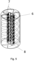
- Fig. 5 shows the separator with three spiral coils.
- the magnetic filter in the assembled state as per Fig. 2 consisting of the hose adapter 2 located at the inlet of the lid 12, external case 4, lid 3 of the external case 4 with the hose adapter 1 at the outlet.
- the case 4 contains the embedded separator 6, along the internal perimeter of which at least one spiral coil 7 is situated.
- the centre of the separator 6 includes one perforated site 8 of the magnet 9, in whose bed the magnet 9 is situated.
- the magnet 9 is closed in the site 8 of the magnet 9 by the lid 10 of the site 8 of the magnet 9.
- the separator 6 is positioned in the external case 4 in a manner delimited by the set spring 11 at the inlet of liquid on one side and by the spacer ring 5 at the outlet of liquid.
- the magnet 9 has its polarity distributed in a sandwich-like manner, i.e. the positive and negative poles extend along the entire length of the magnet 9.
- gas prior to passing the fixed fuel filter, flows through the hose adapter 2 at the inlet of the internal space of the stainless-steel case 4, where in the space of the set spring 11 it is divided into three spiral coils 7 forming the internals of the separator 6 made of ABS plastic material.
- the perforated site 8 of the magnet 9 inside which the neodymium magnet 9 is placed, is positioned.
- Gas flows through the three spiral coils 7 around the site 8 of the magnets 9. Thanks to the circular movement of the gas around the site 8 of the magnet 9 by the spiral coils 7, which are situated along the entire internal perimeter of the case of the circular separator 6, the magnetic force of the magnet 9 entraps metallic shavings present in the gas.
- Magnetic shavings are entrapped by the magnet 9 through the openings in the site 8 of the magnet 9. Some impurities are entrapped on the surface of the site 8, others go through the openings as far as the magnet 9.
- the purified gas after passing through the three spiral coils 7, is mixed again into one flow in the space of the spacer ring 5, leaves the magnetic filter through the hose adapter 1 at the outlet and flows further through the fuel system towards the solid paper filter and towards the motor.
- Diesel oil prior to passing the fixed fuel filter, flows through the hose adapter 2 at the inlet of the internal space of the external stainless-steel case 4, where in the space of the set spring 11 it is divided into two spiral coils 7 forming the internals of the separator 6 made of stainless steel.
- the perforated site 8 of the magnet 9, inside which the ferrite magnet 9 is placed is positioned.
- Diesel oil flows through the two spiral coils 7 around the site 8 of the magnets 9. Thanks to the circular movement of the Diesel oil around the site 8 of the magnet 9 in the spiral coils 7, which are situated along the entire internal perimeter of the case of the circular separator 6, the magnetic force of the magnet 9 entraps metallic shavings present in the Diesel oil.
- Magnetic shavings are entrapped by the magnet 9 through the openings in the site 8 of the magnet 9. Some impurities are entrapped on the surface of the site 8, others go through the openings as far as the magnet 9.
- the spiral coils 7 have indented surface that slows down the flow of Diesel oil through the separator and creates vortices, making it easier for metallic shavings to get entrapped in the site 8 of the magnet 9, or on the magnet 9 itself.
- the purified Diesel oil after passing through the two spiral coils 7 , is mixed again into one flow in the space of the spacer ring 5 , leaves the magnetic filter through the hose adapter 1 at the outlet and flows further through the fuel system towards the solid paper filter and towards the motor.
- Diesel oil prior to passing the fixed fuel filter, flows through the hose adapter 2 at the inlet of the internal space of the external stainless-steel case 4, where, after passing through the space of the set spring 11 , it flows into one spiral coil 7 forming the internals of the separator 6 made of ABS plastic material.
- the perforated site 8 of the magnet 9, inside which the neodymium magnet 9 is placed is positioned.
- Diesel oil flows through one spiral coil 7 around the site 8 of the magnets 9. Thanks to the circular movement of the Diesel oil around the site 8 of the magnet 9 in the spiral coil 7, which is situated along the entire internal perimeter of the case of the circular separator 6, the magnetic force of the magnet 9 entraps metallic shavings present in the Diesel oil.
- Magnetic shavings are entrapped by the magnet 9 through the openings in the site 8 of the magnet 9. Some impurities are entrapped on the surface of the site 8 of the magnet 9, others go through the openings as far as the magnet 9.
- the purified Diesel oil after passing through one spiral coil 7 after passing through the space of the spacer ring 5 , leaves the magnetic filter through the hose adapter 1 at the outlet and flows further through the fuel system towards the solid paper filter and towards the motor.
- the magnetic force of the magnet 9 entraps metallic shavings present in the oil.
- Magnetic shavings are entrapped by the magnet 9 through the openings in the site 8 of the magnet 9.
- Some impurities are entrapped on the surface of the site 8, others go through the openings as far as the magnet 9.
- the purified oil after passing through the three spiral coils 7 , is mixed again into one flow in the space of the spacer ring 5 , leaves the magnetic filter through the hose adapter 1 at the outlet and flows further towards the oil tank from where it is then pumped by the pump back to the system.
- the magnetic filter can be used in particular in the automotive or engineering industries where the elimination of metallic impurities from fuel systems of passenger as well as goods-carrying vehicles will prevent significant damage to the components of the motor, which work with accuracy in the order of millimetres, and with hydraulic systems, damage of the hydrostatic mechanism and its components will be eliminated.
Landscapes
- Engineering & Computer Science (AREA)
- Chemical & Material Sciences (AREA)
- Combustion & Propulsion (AREA)
- Mechanical Engineering (AREA)
- General Engineering & Computer Science (AREA)
- Water Supply & Treatment (AREA)
- Chemical Kinetics & Catalysis (AREA)
- Lubrication Details And Ventilation Of Internal Combustion Engines (AREA)
- Filtration Of Liquid (AREA)
Description
- The invention concerns a magnetic filter for fuel and hydraulic systems to remove metallic impurities, in particular shavings, to be used in fuel systems in the automotive industry on common-rail systems and in hydraulic systems to the full extent of their industrial application.
- A majority of closed circuits filled with liquid are fitted with a mechanical or otherwise active filter through which the liquid flows and by which undesirable substances that could damage other components of the closed circuit are eliminated.
- Within the framework of mechanical non-active filters, solutions restricting the free flow of liquid through the system that allow undesirable mechanical particles present in the liquid to be entrapped are concerned. In the segment of the automotive industry, a solution of the fuel filter in the fuel circuit system that filters fuel coming from the fuel tank is known to remove solid particles and sediments that would otherwise enter the motor that could thus be damaged. Such filters are found in a majority of motors with internal combustion. Such fuel filters have usually the shape of a cylindrical case with an insert made of paper material and they in particular prevent impurities present in the fuel from damaging the downstream components of the fuel system and consequently the entire motor. A disadvantage of this solution is an insufficient entrapment of metallic shavings that go through the paper filter either due to their small size or because they cut through the paper filter. Shavings can be generated, for example, in the fuel system of Diesel vehicles due to low-quality Diesel oil which then poorly lubricates the fuel feed pump in the fuel tank, which results in high friction. The fuel feed pump starts producing invisible metallic shavings which then wear the highpressure pump that will start generating other metallic particles as well. Such tiny metallic particles go through the fuel filter due to their miniature size and enter fuel injectors that will thus become irreversibly damaged. The injectors then fail to feed a sufficient quantity of fuel and the vehicle will become inoperable. The unfavourable consequences of impurities and sediments can be partially mitigated by the application of additives and products designed to clean the system that are able to dissolve solid deposits in the fuel system, carbon in the injection system and exhaust system without the necessity to dismantle any components of the motor. Mechanically inactive filters can also be found in hydraulic systems where among the most frequently used are strainer, slot or other porous filters.
- In addition, a number of technical solutions for active filters utilizing magnetic force are available. In a majority of cases, magnetic filters that are positioned onto heating and cooling systems with circulating water are concerned. Such filters are fitted with a strong permanent magnet separating impurities comprising in particular sand, rust particles and shavings and are also fitted with a filtering sieve to separate other impurities as well. This type of solution is able to capture metallic particles of smaller sizes and functions in environments comprising liquids of lower densities, i.e. for example in aqueous environments. In addition, there are industrial separators operating on the basis of neodymium magnets with/without a separation container representing solutions that can be utilized in hall-based technical plants, i.e. whose sizes are larger than one meter and a number of whom require external power supply.
- In the state-of-the-art area, for example, the following
Czech patent specifications have been found Nos. 76117 162391 116387 135161 JP 2007-75808A - Devices using a spiral and magnets are known, e.g.
DE 17 94 280 B1 andUS 2012/255519 A1 , but disadvantage ofDE 17 94 280 B1 is risk of damage of car engine due to design flaws.DE1794280B1 discloses a magnetic filter according to the preamble of theindependent claim 1. -
US 2012/255519 A1 works as fuel safe application with no function to catch any particles from fuel. - The task of the inventor was to develop a solution that would be applicable in a demanding environment in terms of space, i.e. which would allow installation in already existing limited spatial conditions, in particular the fuel systems of vehicles, and which would also be able to clean the systems from the finest metallic impurities without requiring external power supply.
- These above mentioned drawbacks are eliminated by the magnetic filter consisting of an external case, separator, and magnet according to the present invention, which is based on the fact that the separator has at least one spiral coil situated in its internal case and that a magnet site containing the magnet is situated in the centre of the separator. The magnet site comprises openings through which metallic impurities are entrapped by the magnet.
- the spiral coil surface is roughened by indenting.
- Compared to the state of the art, the magnetic filter according to the present invention has several advantages. In addition to the high efficiency in cleaning liquids from metallic impurities, in particular small dimensions of the technical solution itself and the resulting low demands for installation space are concerned. The invention is characterized by low manufacturing costs compared to those related to the repair of damaged motor components and also by quick assembly onto the existing fuel systems.
- The principle behind the functioning and high efficiency of the invention is the rotational motion of liquid provided by the spiral coil around the magnet. Thanks to its rotation around the magnet, the flow of liquid is slowed down thus allowing magnetic force to act in a more efficient way over a longer period of time on the liquid and metallic shavings present in it. The magnet used in the invention and placed in the site reserved for magnets has its polarity distributed in a sandwich-like manner along its entire length. Therefore, it acts on the liquid over the entire period of its rotational motion through the separator and its spiral coil designed to entrap metallic shavings.
- The invention will be explained in detail by the drawing where
Fig. 1 provides the exploded view of the magnetic filter if its individual components are viewed from the side,Fig. 2 provides the assembled view of the magnetic filter if viewed from the side,Fig. 3 shows the axonometric view of the magnetic filter in its assembled state, andFig. 4 shows the axonometric view of the exploded magnetic filter.Fig. 5 shows the separator with three spiral coils. - The magnetic filter in the assembled state as per
Fig. 2 consisting of thehose adapter 2 located at the inlet of thelid 12,external case 4,lid 3 of theexternal case 4 with thehose adapter 1 at the outlet. In the assembled state, thecase 4 contains the embeddedseparator 6, along the internal perimeter of which at least onespiral coil 7 is situated. The centre of theseparator 6 includes oneperforated site 8 of themagnet 9, in whose bed themagnet 9 is situated. Themagnet 9 is closed in thesite 8 of themagnet 9 by thelid 10 of thesite 8 of themagnet 9. Theseparator 6 is positioned in theexternal case 4 in a manner delimited by theset spring 11 at the inlet of liquid on one side and by thespacer ring 5 at the outlet of liquid.
Themagnet 9 has its polarity distributed in a sandwich-like manner, i.e. the positive and negative poles extend along the entire length of themagnet 9. - In the fuel system, gas, prior to passing the fixed fuel filter, flows through the
hose adapter 2 at the inlet of the internal space of the stainless-steel case 4, where in the space of theset spring 11 it is divided into threespiral coils 7 forming the internals of theseparator 6 made of ABS plastic material. In the middle of theseparator 6, theperforated site 8 of themagnet 9, inside which theneodymium magnet 9 is placed, is positioned. Gas flows through the threespiral coils 7 around thesite 8 of themagnets 9. Thanks to the circular movement of the gas around thesite 8 of themagnet 9 by thespiral coils 7, which are situated along the entire internal perimeter of the case of thecircular separator 6, the magnetic force of themagnet 9 entraps metallic shavings present in the gas. Magnetic shavings are entrapped by themagnet 9 through the openings in thesite 8 of themagnet 9. Some impurities are entrapped on the surface of thesite 8, others go through the openings as far as themagnet 9. The purified gas, after passing through the threespiral coils 7, is mixed again into one flow in the space of thespacer ring 5, leaves the magnetic filter through thehose adapter 1 at the outlet and flows further through the fuel system towards the solid paper filter and towards the motor. - In the fuel system, Diesel oil, prior to passing the fixed fuel filter, flows through the
hose adapter 2 at the inlet of the internal space of the external stainless-steel case 4, where in the space of theset spring 11 it is divided into twospiral coils 7 forming the internals of theseparator 6 made of stainless steel. In the middle of theseparator 6, theperforated site 8 of themagnet 9, inside which theferrite magnet 9 is placed, is positioned. Diesel oil flows through the twospiral coils 7 around thesite 8 of themagnets 9. Thanks to the circular movement of the Diesel oil around thesite 8 of themagnet 9 in the spiral coils 7, which are situated along the entire internal perimeter of the case of thecircular separator 6, the magnetic force of themagnet 9 entraps metallic shavings present in the Diesel oil. Magnetic shavings are entrapped by themagnet 9 through the openings in thesite 8 of themagnet 9. Some impurities are entrapped on the surface of thesite 8, others go through the openings as far as themagnet 9. The spiral coils 7 have indented surface that slows down the flow of Diesel oil through the separator and creates vortices, making it easier for metallic shavings to get entrapped in thesite 8 of themagnet 9, or on themagnet 9 itself. The purified Diesel oil, after passing through the twospiral coils 7, is mixed again into one flow in the space of thespacer ring 5, leaves the magnetic filter through thehose adapter 1 at the outlet and flows further through the fuel system towards the solid paper filter and towards the motor. - In the fuel system, Diesel oil, prior to passing the fixed fuel filter, flows through the
hose adapter 2 at the inlet of the internal space of the external stainless-steel case 4, where, after passing through the space of theset spring 11, it flows into onespiral coil 7 forming the internals of theseparator 6 made of ABS plastic material. In the middle of theseparator 6, theperforated site 8 of themagnet 9, inside which theneodymium magnet 9 is placed, is positioned. Diesel oil flows through onespiral coil 7 around thesite 8 of themagnets 9. Thanks to the circular movement of the Diesel oil around thesite 8 of themagnet 9 in thespiral coil 7, which is situated along the entire internal perimeter of the case of thecircular separator 6, the magnetic force of themagnet 9 entraps metallic shavings present in the Diesel oil. Magnetic shavings are entrapped by themagnet 9 through the openings in thesite 8 of themagnet 9. Some impurities are entrapped on the surface of thesite 8 of themagnet 9, others go through the openings as far as themagnet 9. The purified Diesel oil, after passing through onespiral coil 7 after passing through the space of thespacer ring 5, leaves the magnetic filter through thehose adapter 1 at the outlet and flows further through the fuel system towards the solid paper filter and towards the motor. - In the hydraulic circuit, excessive oil flows through the safety by-pass valve to the manifold, where, along its way back to the oil tank, it flows through the
hose adapter 2 at the inlet of the internal space of the external stainless-steel case 4, where in the space of theset spring 11 it is divided into threespiral coils 7 forming the internals of theseparator 6 made of ABS plastic material. In the middle of theseparator 6, theperforated site 8 of themagnet 9, inside which theneodymium magnet 9 is placed, is positioned. Oil flows through the threespiral coils 7 around thesite 8 of themagnets 9. Thanks to the circular movement of the oil around thesite 8 of themagnet 9 in the spiral coils 7, which are situated along the entire internal perimeter of the case of thecircular separator 6, the magnetic force of themagnet 9 entraps metallic shavings present in the oil. Magnetic shavings are entrapped by themagnet 9 through the openings in thesite 8 of themagnet 9. Some impurities are entrapped on the surface of thesite 8, others go through the openings as far as themagnet 9. The purified oil, after passing through the threespiral coils 7, is mixed again into one flow in the space of thespacer ring 5, leaves the magnetic filter through thehose adapter 1 at the outlet and flows further towards the oil tank from where it is then pumped by the pump back to the system. - The magnetic filter can be used in particular in the automotive or engineering industries where the elimination of metallic impurities from fuel systems of passenger as well as goods-carrying vehicles will prevent significant damage to the components of the motor, which work with accuracy in the order of millimetres, and with hydraulic systems, damage of the hydrostatic mechanism and its components will be eliminated.
-
- 1 hose adapter at the outlet
- 2 hose adapter at the inlet
- 3 lid of the case at the outlet
- 4 external case
- 5 spacer ring
- 6 separator
- 7 spiral coil
- 8 site of the magnet
- 9 magnet
- 10 lid of the site of the magnet
- 11 set spring
- 12 lid of the case at the inlet
Claims (2)
- Magnetic filter for removing metallic impurities, the magnetic filter consisting of an external case (4), a separator (6), and a magnet (9), wherein the separator (6) is fitted in its internal case with at least one spiral coil (7), wherein a magnet site (8) containing the magnet (9) is situated in the centre of the separator (6) characterized in that the magnet site (8) comprises openings through which metallic impurities are entrapped by the magnet (9).
- Magnetic filter according to claim 1, characterized in that the spiral coil (7) has its surface roughened by indenting.
Applications Claiming Priority (2)
| Application Number | Priority Date | Filing Date | Title |
|---|---|---|---|
| CZ2019-567A CZ2019567A3 (en) | 2019-09-05 | 2019-09-05 | Magnetic filter |
| PCT/IB2020/056296 WO2021044225A1 (en) | 2019-09-05 | 2020-07-03 | Magnetic filter |
Publications (3)
| Publication Number | Publication Date |
|---|---|
| EP4025347A1 EP4025347A1 (en) | 2022-07-13 |
| EP4025347B1 true EP4025347B1 (en) | 2025-02-19 |
| EP4025347C0 EP4025347C0 (en) | 2025-02-19 |
Family
ID=72147142
Family Applications (1)
| Application Number | Title | Priority Date | Filing Date |
|---|---|---|---|
| EP20742491.2A Active EP4025347B1 (en) | 2019-09-05 | 2020-07-03 | Magnetic filter |
Country Status (5)
| Country | Link |
|---|---|
| EP (1) | EP4025347B1 (en) |
| CZ (1) | CZ2019567A3 (en) |
| ES (1) | ES3021811T3 (en) |
| PL (1) | PL4025347T3 (en) |
| WO (1) | WO2021044225A1 (en) |
Families Citing this family (1)
| Publication number | Priority date | Publication date | Assignee | Title |
|---|---|---|---|---|
| US11786913B2 (en) * | 2021-05-14 | 2023-10-17 | Saudi Arabian Oil Company | Y-shaped magnetic filtration device |
Family Cites Families (9)
| Publication number | Priority date | Publication date | Assignee | Title |
|---|---|---|---|---|
| DE1794280B1 (en) * | 1968-05-14 | 1971-02-11 | Stelzner & Co | Magnetic filter device |
| IT1217933B (en) * | 1988-06-27 | 1990-03-30 | Dario Beruto | DEVICE AND METHOD FOR THE MODIFICATION OF ACTIVITIES OF MICROORGANISMS CONTAINED IN LIQUIDS WITHOUT ADDITION OF CHEMICAL REAGENTS |
| CN2145876Y (en) * | 1992-11-29 | 1993-11-10 | 丁黔 | Magnetic filter |
| US5882514A (en) * | 1996-08-22 | 1999-03-16 | Fletcher; Charles J. | Apparatus for magnetically treating fluids |
| US6210572B1 (en) * | 1999-10-18 | 2001-04-03 | Technology Commercialization Corp. | Filter and method for purifying liquids containing magnetic particles |
| JP3911516B2 (en) * | 2005-08-18 | 2007-05-09 | 隆 篠崎 | oil filter |
| CN101922327A (en) * | 2010-08-30 | 2010-12-22 | 四平大吉强磁滤清器有限公司 | Magnetic filter of engine |
| CA2736337A1 (en) * | 2011-04-05 | 2012-10-05 | Claude L. Hebert | Fuel treatment |
| CN207142827U (en) * | 2017-05-23 | 2018-03-27 | 鸿洋集团有限公司 | A kind of Magnetic filtration device oil sight device |
-
2019
- 2019-09-05 CZ CZ2019-567A patent/CZ2019567A3/en unknown
-
2020
- 2020-07-03 ES ES20742491T patent/ES3021811T3/en active Active
- 2020-07-03 PL PL20742491.2T patent/PL4025347T3/en unknown
- 2020-07-03 WO PCT/IB2020/056296 patent/WO2021044225A1/en not_active Ceased
- 2020-07-03 EP EP20742491.2A patent/EP4025347B1/en active Active
Also Published As
| Publication number | Publication date |
|---|---|
| CZ308457B6 (en) | 2020-08-26 |
| ES3021811T3 (en) | 2025-05-27 |
| WO2021044225A1 (en) | 2021-03-11 |
| PL4025347T3 (en) | 2025-06-09 |
| EP4025347A1 (en) | 2022-07-13 |
| CZ2019567A3 (en) | 2020-08-26 |
| EP4025347C0 (en) | 2025-02-19 |
Similar Documents
| Publication | Publication Date | Title |
|---|---|---|
| US5089129A (en) | Fluid contaminate filtration system including a filter, a contaminate particle trap, and a cold start fluid circulation system | |
| US6210572B1 (en) | Filter and method for purifying liquids containing magnetic particles | |
| JP2006242180A (en) | Fluid housing used for fluid containing particulate, transmission system using it, sheet installed in it, and method and system for catching particulate contained in fluid in it | |
| EP4025347B1 (en) | Magnetic filter | |
| US7922005B2 (en) | Removable shield in an engine oil strainer | |
| US20130105379A1 (en) | Magnetic Fluid Filter | |
| CN1919467B (en) | Oil filter | |
| US5389252A (en) | Magnetic filter aid | |
| CN103089751A (en) | Modified oil filter | |
| CN210509325U (en) | Oil filter with magnetic ring | |
| KR100666134B1 (en) | Diesel fuel filtering device | |
| CN203515726U (en) | Engine and magnetic filter thereof | |
| RU197879U1 (en) | Magneto-hydrodynamic filter | |
| KR100933941B1 (en) | Automatic Liquid Fuel Filter | |
| CN108019617B (en) | Grease filter | |
| CN202360515U (en) | Improved oil filter | |
| JP4402748B2 (en) | Separation device for magnetic particles in transmission lubricant | |
| WO1996022461A1 (en) | Magnetic fuel treatment device and method | |
| US11007459B2 (en) | Fuel pre-filtering element | |
| US10751650B2 (en) | Bypass filter method and device | |
| CN208545254U (en) | Sewage disposal system | |
| CN215609877U (en) | Lubricating oil filtering and purifying system | |
| CN221169691U (en) | Engine oil filter element and ultrahigh-pressure fuel injection pump with same | |
| CN103511023B (en) | Engine and magnetic filter thereof | |
| RU2232622C2 (en) | Device for cleaning filtering surface, deaeration of dispersed system being filtered and desorption of it from liquid dispersed medium of gases and/or foreign liquid admixtures |
Legal Events
| Date | Code | Title | Description |
|---|---|---|---|
| STAA | Information on the status of an ep patent application or granted ep patent |
Free format text: STATUS: UNKNOWN |
|
| STAA | Information on the status of an ep patent application or granted ep patent |
Free format text: STATUS: THE INTERNATIONAL PUBLICATION HAS BEEN MADE |
|
| PUAI | Public reference made under article 153(3) epc to a published international application that has entered the european phase |
Free format text: ORIGINAL CODE: 0009012 |
|
| STAA | Information on the status of an ep patent application or granted ep patent |
Free format text: STATUS: REQUEST FOR EXAMINATION WAS MADE |
|
| 17P | Request for examination filed |
Effective date: 20220405 |
|
| AK | Designated contracting states |
Kind code of ref document: A1 Designated state(s): AL AT BE BG CH CY CZ DE DK EE ES FI FR GB GR HR HU IE IS IT LI LT LU LV MC MK MT NL NO PL PT RO RS SE SI SK SM TR |
|
| DAV | Request for validation of the european patent (deleted) | ||
| DAX | Request for extension of the european patent (deleted) | ||
| GRAP | Despatch of communication of intention to grant a patent |
Free format text: ORIGINAL CODE: EPIDOSNIGR1 |
|
| STAA | Information on the status of an ep patent application or granted ep patent |
Free format text: STATUS: GRANT OF PATENT IS INTENDED |
|
| INTG | Intention to grant announced |
Effective date: 20241009 |
|
| GRAS | Grant fee paid |
Free format text: ORIGINAL CODE: EPIDOSNIGR3 |
|
| GRAA | (expected) grant |
Free format text: ORIGINAL CODE: 0009210 |
|
| STAA | Information on the status of an ep patent application or granted ep patent |
Free format text: STATUS: THE PATENT HAS BEEN GRANTED |
|
| AK | Designated contracting states |
Kind code of ref document: B1 Designated state(s): AL AT BE BG CH CY CZ DE DK EE ES FI FR GB GR HR HU IE IS IT LI LT LU LV MC MK MT NL NO PL PT RO RS SE SI SK SM TR |
|
| REG | Reference to a national code |
Ref country code: GB Ref legal event code: FG4D |
|
| REG | Reference to a national code |
Ref country code: CH Ref legal event code: EP |
|
| REG | Reference to a national code |
Ref country code: DE Ref legal event code: R096 Ref document number: 602020046315 Country of ref document: DE |
|
| REG | Reference to a national code |
Ref country code: IE Ref legal event code: FG4D |
|
| U01 | Request for unitary effect filed |
Effective date: 20250310 |
|
| U07 | Unitary effect registered |
Designated state(s): AT BE BG DE DK EE FI FR IT LT LU LV MT NL PT RO SE SI Effective date: 20250318 |
|
| REG | Reference to a national code |
Ref country code: ES Ref legal event code: FG2A Ref document number: 3021811 Country of ref document: ES Kind code of ref document: T3 Effective date: 20250527 |
|
| PG25 | Lapsed in a contracting state [announced via postgrant information from national office to epo] |
Ref country code: RS Free format text: LAPSE BECAUSE OF FAILURE TO SUBMIT A TRANSLATION OF THE DESCRIPTION OR TO PAY THE FEE WITHIN THE PRESCRIBED TIME-LIMIT Effective date: 20250519 |
|
| PGFP | Annual fee paid to national office [announced via postgrant information from national office to epo] |
Ref country code: PL Payment date: 20250317 Year of fee payment: 6 |
|
| PG25 | Lapsed in a contracting state [announced via postgrant information from national office to epo] |
Ref country code: IS Free format text: LAPSE BECAUSE OF FAILURE TO SUBMIT A TRANSLATION OF THE DESCRIPTION OR TO PAY THE FEE WITHIN THE PRESCRIBED TIME-LIMIT Effective date: 20250619 Ref country code: NO Free format text: LAPSE BECAUSE OF FAILURE TO SUBMIT A TRANSLATION OF THE DESCRIPTION OR TO PAY THE FEE WITHIN THE PRESCRIBED TIME-LIMIT Effective date: 20250519 |
|
| PG25 | Lapsed in a contracting state [announced via postgrant information from national office to epo] |
Ref country code: HR Free format text: LAPSE BECAUSE OF FAILURE TO SUBMIT A TRANSLATION OF THE DESCRIPTION OR TO PAY THE FEE WITHIN THE PRESCRIBED TIME-LIMIT Effective date: 20250219 |
|
| PG25 | Lapsed in a contracting state [announced via postgrant information from national office to epo] |
Ref country code: GR Free format text: LAPSE BECAUSE OF FAILURE TO SUBMIT A TRANSLATION OF THE DESCRIPTION OR TO PAY THE FEE WITHIN THE PRESCRIBED TIME-LIMIT Effective date: 20250520 |
|
| PGFP | Annual fee paid to national office [announced via postgrant information from national office to epo] |
Ref country code: TR Payment date: 20250409 Year of fee payment: 6 |
|
| U20 | Renewal fee for the european patent with unitary effect paid |
Year of fee payment: 6 Effective date: 20250731 |
|
| PG25 | Lapsed in a contracting state [announced via postgrant information from national office to epo] |
Ref country code: SM Free format text: LAPSE BECAUSE OF FAILURE TO SUBMIT A TRANSLATION OF THE DESCRIPTION OR TO PAY THE FEE WITHIN THE PRESCRIBED TIME-LIMIT Effective date: 20250219 |
|
| PGFP | Annual fee paid to national office [announced via postgrant information from national office to epo] |
Ref country code: ES Payment date: 20250801 Year of fee payment: 6 |
|
| PG25 | Lapsed in a contracting state [announced via postgrant information from national office to epo] |
Ref country code: CZ Free format text: LAPSE BECAUSE OF FAILURE TO SUBMIT A TRANSLATION OF THE DESCRIPTION OR TO PAY THE FEE WITHIN THE PRESCRIBED TIME-LIMIT Effective date: 20250219 |
|
| PG25 | Lapsed in a contracting state [announced via postgrant information from national office to epo] |
Ref country code: SK Free format text: LAPSE BECAUSE OF FAILURE TO SUBMIT A TRANSLATION OF THE DESCRIPTION OR TO PAY THE FEE WITHIN THE PRESCRIBED TIME-LIMIT Effective date: 20250219 |
|
| PLBE | No opposition filed within time limit |
Free format text: ORIGINAL CODE: 0009261 |
|
| STAA | Information on the status of an ep patent application or granted ep patent |
Free format text: STATUS: NO OPPOSITION FILED WITHIN TIME LIMIT |
|
| REG | Reference to a national code |
Ref country code: CH Ref legal event code: L10 Free format text: ST27 STATUS EVENT CODE: U-0-0-L10-L00 (AS PROVIDED BY THE NATIONAL OFFICE) Effective date: 20251231 |
|
| 26N | No opposition filed |
Effective date: 20251120 |
|
| REG | Reference to a national code |
Ref country code: CH Ref legal event code: H13 Free format text: ST27 STATUS EVENT CODE: U-0-0-H10-H13 (AS PROVIDED BY THE NATIONAL OFFICE) Effective date: 20260224 |
|
| GBPC | Gb: european patent ceased through non-payment of renewal fee |
Effective date: 20250703 |
|
| PG25 | Lapsed in a contracting state [announced via postgrant information from national office to epo] |
Ref country code: GB Free format text: LAPSE BECAUSE OF NON-PAYMENT OF DUE FEES Effective date: 20250703 |
|
| PG25 | Lapsed in a contracting state [announced via postgrant information from national office to epo] |
Ref country code: CH Free format text: LAPSE BECAUSE OF NON-PAYMENT OF DUE FEES Effective date: 20250731 |