EP4025139B1 - Sleeve for rotary surgical instrument - Google Patents
Sleeve for rotary surgical instrument Download PDFInfo
- Publication number
- EP4025139B1 EP4025139B1 EP20768714.6A EP20768714A EP4025139B1 EP 4025139 B1 EP4025139 B1 EP 4025139B1 EP 20768714 A EP20768714 A EP 20768714A EP 4025139 B1 EP4025139 B1 EP 4025139B1
- Authority
- EP
- European Patent Office
- Prior art keywords
- sleeve
- lumen
- shield
- irrigation
- distal
- Prior art date
- Legal status (The legal status is an assumption and is not a legal conclusion. Google has not performed a legal analysis and makes no representation as to the accuracy of the status listed.)
- Active
Links
Images





Classifications
-
- A—HUMAN NECESSITIES
- A61—MEDICAL OR VETERINARY SCIENCE; HYGIENE
- A61B—DIAGNOSIS; SURGERY; IDENTIFICATION
- A61B17/00—Surgical instruments, devices or methods
- A61B17/32—Surgical cutting instruments
- A61B17/320016—Endoscopic cutting instruments, e.g. arthroscopes, resectoscopes
- A61B17/32002—Endoscopic cutting instruments, e.g. arthroscopes, resectoscopes with continuously rotating, oscillating or reciprocating cutting instruments
-
- A—HUMAN NECESSITIES
- A61—MEDICAL OR VETERINARY SCIENCE; HYGIENE
- A61B—DIAGNOSIS; SURGERY; IDENTIFICATION
- A61B17/00—Surgical instruments, devices or methods
- A61B17/16—Instruments for performing osteoclasis; Drills or chisels for bones; Trepans
- A61B17/1644—Instruments for performing osteoclasis; Drills or chisels for bones; Trepans using fluid other than turbine drive fluid
-
- A—HUMAN NECESSITIES
- A61—MEDICAL OR VETERINARY SCIENCE; HYGIENE
- A61B—DIAGNOSIS; SURGERY; IDENTIFICATION
- A61B17/00—Surgical instruments, devices or methods
- A61B17/16—Instruments for performing osteoclasis; Drills or chisels for bones; Trepans
- A61B17/1613—Component parts
- A61B17/1633—Sleeves, i.e. non-rotating parts surrounding the bit shaft, e.g. the sleeve forming a single unit with the bit shaft
-
- A—HUMAN NECESSITIES
- A61—MEDICAL OR VETERINARY SCIENCE; HYGIENE
- A61B—DIAGNOSIS; SURGERY; IDENTIFICATION
- A61B17/00—Surgical instruments, devices or methods
- A61B17/34—Trocars; Puncturing needles
- A61B17/3417—Details of tips or shafts, e.g. grooves, expandable, bendable; Multiple coaxial sliding cannulas, e.g. for dilating
- A61B17/3421—Cannulas
- A61B2017/3443—Cannulas with means for adjusting the length of a cannula
-
- A—HUMAN NECESSITIES
- A61—MEDICAL OR VETERINARY SCIENCE; HYGIENE
- A61B—DIAGNOSIS; SURGERY; IDENTIFICATION
- A61B90/00—Instruments, implements or accessories specially adapted for surgery or diagnosis and not covered by any of the groups A61B1/00 - A61B50/00, e.g. for luxation treatment or for protecting wound edges
- A61B90/06—Measuring instruments not otherwise provided for
- A61B2090/062—Measuring instruments not otherwise provided for penetration depth
-
- A—HUMAN NECESSITIES
- A61—MEDICAL OR VETERINARY SCIENCE; HYGIENE
- A61B—DIAGNOSIS; SURGERY; IDENTIFICATION
- A61B90/00—Instruments, implements or accessories specially adapted for surgery or diagnosis and not covered by any of the groups A61B1/00 - A61B50/00, e.g. for luxation treatment or for protecting wound edges
- A61B90/08—Accessories or related features not otherwise provided for
- A61B2090/0801—Prevention of accidental cutting or pricking
-
- A—HUMAN NECESSITIES
- A61—MEDICAL OR VETERINARY SCIENCE; HYGIENE
- A61B—DIAGNOSIS; SURGERY; IDENTIFICATION
- A61B2217/00—General characteristics of surgical instruments
- A61B2217/002—Auxiliary appliance
- A61B2217/007—Auxiliary appliance with irrigation system
Definitions
- US 2017/0042528 A1 discloses an ultrasonic aspirator which includes a body, a shield, an endoscope, a headpiece to vibrate and destroy tissue and an irrigation tube adapted to provide fluid to the body and the headpiece via an irrigation port for removing destroyed tissue.
- the shield is adapted to carry fluid for aspiration of sonicated tissue.
- An endoscope tube extends from the endoscope toward the headpiece and has an endoscope opening proximal of the headpiece to the body.
- the irrigation sleeve is for use with a surgical system comprising an irrigation source, a rotary instrument having a tube extending to a distal tube end, and a cutting accessory having a head and a shank adapted to be rotatably supported by the tube of the rotary instrument, wherein the irrigation sleeve includes a sleeve body extending between a proximal sleeve portion and a distal sleeve portion; a first lumen formed in the sleeve body for receiving at least a portion of the tube of the rotary instrument; a second lumen formed in the sleeve body and spaced out of fluid communication with the first lumen; a shield extension coupled to the sleeve body and extending between a proximal shield portion and a distal shield portion, the proximal shield portion engaged with the
- the method further comprises a step of and inserting the cutting accessory 52 through the lumen 118 and engaging the shank 66 with the rotary instrument 44.
- a close up section view of the cutting accessory 52 inserted through the lumen 118 with the head 64 arranged adjacent to the distal shield portion 144 is shown.
- the weakened segment 176 has been removed from the distal shield portion 144 and is spaced from the irrigation sleeve 100 showing where the head 64 of the cutting accessory 52 would otherwise interfere with the irrigation sleeve 100.
- the surgical system 40 comprises the rotary instrument 44, the cutting accessory 52, and the irrigation sleeve 100, which is installed on the rotary instrument 44.
- the rotary instrument of Figures 3 and 17 comprises a tube 60 that is longer.
- the scope of the invention is defined by the appended claims.
- the irrigation sleeve 100 is shown removed from the rotary instrument 44 and the cutting accessory 52 in Figures 18 and 19 .
- both the first end 102 and the working end 104 of the irrigation sleeve 100 can be seen, showing the increased length of the sleeve body 106.
- the increased length of the sleeve body 106 allows the first lumen 118 to be correspondingly increased in size to accommodate the longer tube 60.
- different lengths of the proximal sleeve portion 130 and the distal sleeve portion 132 can be provided to suit different rotary instruments 44 within the scope of the present disclosure.
- the lengths of the shield extension 128 and to the sleeve body 106 can be supplied in standard increments to facilitate customization of the irrigation sleeve 100 to lengths falling between each standard increment.
- Figures 20-25 show two alternative implementations of the irrigation lumen of the irrigation sleeve.
- the irrigation sleeve 100', 100" may be similar to that previously described with like numerals (plus a prime or double prim symbol e.g. 100' and 100") corresponding to like components, and any disclosure common to the corresponding components may be considered omitted in the interest of brevity should not be construed as limiting.
- Figures 20-22 show a punched feature 202' and Figures 23-25 show a skived feature 204".
- the skived feature 204" is arranged near the distal sleeve end 110" of the sleeve body 106" and modifies the outer surface 114" of the sleeve body 106" by locally reducing a thickness of the sleeve body 106" such that the outlet surface 206" is defined adjacent to the outer surface 114".
- the outlet surface 206" is generally perpendicular to the fluid jet FJ (see Figure 4 ) such that fluid is directed out of the lumen outlet 124" toward the desired location.
- the fluid jet FJ may be approximately parallel to the longitudinal axis A1 (see Figure 18 ) extending through the sleeve body 106', as the case may be.
- irrigation sleeve 100 refers to one type of instrument sleeve, which is capable of providing irrigation to a location near the surgical site.
Landscapes
- Health & Medical Sciences (AREA)
- Surgery (AREA)
- Life Sciences & Earth Sciences (AREA)
- Biomedical Technology (AREA)
- Medical Informatics (AREA)
- Orthopedic Medicine & Surgery (AREA)
- Veterinary Medicine (AREA)
- Engineering & Computer Science (AREA)
- Public Health (AREA)
- Heart & Thoracic Surgery (AREA)
- Nuclear Medicine, Radiotherapy & Molecular Imaging (AREA)
- Molecular Biology (AREA)
- Animal Behavior & Ethology (AREA)
- General Health & Medical Sciences (AREA)
- Dentistry (AREA)
- Oral & Maxillofacial Surgery (AREA)
- Surgical Instruments (AREA)
Description
- The subject patent application claims priority to and all the benefits of United States Provisional
Patent Application Nº 62/896,056, filed on 05 September, 2019. - Conventional medical procedures routinely involve the use of surgical tools to assist medical professionals in approaching, viewing, manipulating, or otherwise effecting treatment at localized surgical sites. Some of these medical procedures may involve surgical techniques such as drilling, shaping, or decortication of bone using a rotary instrument, where a cutting accessory, such as a high-speed bur, rotates at speeds in excess of 75k rpm to remove tissue. During use, contact between non-cutting portions of the bur (e.g., a shank) and soft tissue can result in tissue wrap, in which friction between the rotating shank and the soft tissue causes the soft tissue to be pulled around the shank. Surgeons must be mindful to avoid unexpected tissue wrap.
-
US 2017/0042528 A1 discloses an ultrasonic aspirator which includes a body, a shield, an endoscope, a headpiece to vibrate and destroy tissue and an irrigation tube adapted to provide fluid to the body and the headpiece via an irrigation port for removing destroyed tissue. The shield is adapted to carry fluid for aspiration of sonicated tissue. An endoscope tube extends from the endoscope toward the headpiece and has an endoscope opening proximal of the headpiece to the body. - An irrigation sleeve with the features of claim 1 is provided. Further, optional features of the irrigation sleeve are defined in the dependent claims. In particular, the irrigation sleeve is for use with a surgical system comprising an irrigation source, a rotary instrument having a tube extending to a distal tube end, and a cutting accessory having a head and a shank adapted to be rotatably supported by the tube of the rotary instrument, wherein the irrigation sleeve includes a sleeve body extending between a proximal sleeve portion and a distal sleeve portion; a first lumen formed in the sleeve body for receiving at least a portion of the tube of the rotary instrument; a second lumen formed in the sleeve body and spaced out of fluid communication with the first lumen; a shield extension coupled to the sleeve body and extending between a proximal shield portion and a distal shield portion, the proximal shield portion engaged with the distal sleeve portion, the shield extension adapted to minimize tissue wrap about the cutting accessory shank; and a third lumen formed in the shield extension and in communication with the first lumen.
- Advantages of the present disclosure will be readily appreciated as the same becomes better understood by reference to the following detailed description when considered in connection with the accompanying drawings.
-
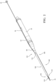
Figure 1 is a schematic view of a surgical system comprising a console, an irrigation source, and a rotary instrument with a cutting accessory, shown with an irrigation sleeve coupled to the rotary instrument. -
Figure 2 is a perspective view of the rotary instrument, the cutting accessory, and the irrigation sleeve ofFigure 1 . -
Figure 3 is an enlarged perspective view of the rotary instrument, the cutting accessory, and the irrigation sleeve according to one embodiment. -
Figure 4 is a partial perspective view of the rotary instrument, the cutting accessory, and the irrigation sleeve ofFigure 2 , shown with a jet of fluid projecting next to and beyond the cutting accessory towards an illustrative surgical site comprising vertebral bone. -
Figure 5 is an exploded perspective view of the rotary instrument, the cutting accessory, and the irrigation sleeve ofFigure 4 , the rotary instrument comprising a tube. -
Figure 6 is an enlarged, partial perspective view of a distal portion of the irrigation sleeve ofFigures 3-5 . -
Figure 7 is an enlarged, perspective view of a proximal portion of the irrigation sleeve ofFigure 6 . -
Figure 8 is a partial section view through a vertical plane on line 8-8 inFigure 7 showing the irrigation sleeve comprising a pilot member, the pilot member being spaced from a distal tube end of the rotary instrument tube. -
Figure 9 is a partial section view through a vertical plane on line 8-8 inFigure 7 showing the irrigation sleeve and the rotary instrument tube according to another embodiment, shown with a first alternative cutting accessory. -
Figure 10 is a partial section view through a vertical plane on line 8-8 ofFigure 7 showing the irrigation sleeve and the rotary instrument tube ofFigure 9 , shown with a second alternative cutting accessory. -
Figure 11 is a partial section view through a vertical plane on line 8-8 ofFigure 7 showing the irrigation sleeve and the rotary instrument tube ofFigure 9 , shown with a portion of the irrigation sleeve removed and a third alternative cutting accessory. -
Figure 12 is an exploded perspective view of the rotary instrument, the cutting accessory, and the irrigation sleeve ofFigure 5 , shown with the irrigation sleeve assembled on the rotary instrument. -
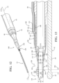
Figure 13 is a partial section view through a vertical plane on line 13-13 ofFigure 12 showing the rotary instrument, the cutting accessory, and the irrigation sleeve and showing a severing line. -
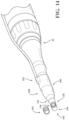
Figure 14 is a partial perspective view of the rotary instrument and the irrigation sleeve ofFigures 12 and 13 , shown with a distal portion of the irrigation sleeve in a pre- and post-removed position. -
Figure 15 is a partial section view through a vertical plane on line 15-15 ofFigure 16 showing the rotary instrument and the irrigation sleeve ofFigures 12-14 , shown with the cutting accessory installed in the rotary instrument and showing the removed distal portion of the irrigation sleeve. -
Figure 16 is a partial perspective view of the rotary instrument, the cutting accessory, and the irrigation sleeve ofFigures 12-15 . -
Figure 17 is a partial perspective view of the distal portion of the irrigation sleeve and the cutting accessory, according to another embodiment. -
Figure 18 is a perspective view of the proximal portion of the irrigation sleeve ofFigure 17 . -
Figure 19 is a split section-view through a vertical plane on line 19-19 ofFigure 18 showing the irrigation sleeve ofFigures 17 and 18 . -
Figure 20 is a perspective view of another embodiment of the irrigation sleeve shown with a punched feature defined in a distal body portion. -
Figure 21 is an enlarged, partial perspective view of a distal end of the irrigation sleeve with the punched feature ofFigure 20 . -
Figure 22 is a cross-sectional view taken along line 22-22 inFigure 21 of the distal end of the irrigation sleeve with the punched feature. -
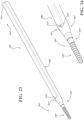
Figure 23 is a perspective view of another embodiment of the irrigation sleeve shown with a skived feature defined in a distal body portion. -
Figure 24 is an enlarged, partial perspective view of a distal end of the irrigation sleeve with the skived feature ofFigure 23 . -
Figure 25 is a cross-sectional view taken along line 25-25 inFigure 24 of the distal end of the irrigation sleeve with the skived feature. - With reference to the Figures, wherein like numerals indicate like parts throughout the several views, a
surgical system 40 is shown inFigure 1 . Thesurgical system 40 generally comprises anirrigation system 42 and a surgical tool, each of which will be described in greater detail below. In the representative embodiment illustrated herein, the surgical tool is realized as arotary instrument 44. Aconsole 46 is employed to control both theirrigation system 42 and the surgical tool via afootswitch 48. However, as will be appreciated from the subsequent description below, both theirrigation system 42 and the surgical tool could be configured and controlled in a number of different ways. By way of non-limiting example, the surgical tool and theirrigation system 42 could be controlled independently, such as by discrete consoles or input devices. Suitable construction and operation of several subsystems of thesurgical system 40 andirrigation system 42 are disclosed in commonly owned International Publication No.WO 2019/022791, filed on February 05, 2018 . - The use of high-speed drills, rotating burs, open-window shavers, and the like necessarily results in the accumulation of debris at the
surgical site 86. Here, thesurgical system 40 employs theirrigation system 42 to direct fluid towards thesurgical site 86 to loosen, float, or displace debris for subsequent removal (for example, by suction). Theirrigation system 42 may also be used to ensure proper operation of surgical tools during procedures by clearing debris from endoscopes, cooling cutting accessories, preventing the accumulation of debris on cutting accessories, and the like. - Referring to
Figures 2-5 , the surgical tool is configured as therotary instrument 44, which drives a cutting accessory, generally indicated at 52. Here, thecutting accessory 52 is adapted to assist a medical professional in approaching or manipulating asurgical site 86 by effecting the removal of tissue, bone, and the like. To this end, thecutting accessory 52 is depicted throughout the drawings as a bur. Thecutting accessory 52 could be of a number of different types or configurations, such as shavers, rasps, ultrasonic cutting tools, etc. As will be discussed below, several cutting accessories 52 (seeFigures 9-11 ) are available to suit the needs associated with varioussurgical sites 86. Specifically, differentlength cutting accessories rotary instrument 44. While the representative surgical tool illustrated herein is realized as arotary instrument 44, the surgical tool could be configured in a number of different ways, including but not limited to an endoscope, a reciprocating tool, un ultrasonic tool, and the like, from any number of components controlled in any suitable way and operable to power thecutting accessory 52. - The
rotary instrument 44 generally comprises ahousing 54, which supports acoupler 56 and a motor 58 therein (depicted schematically inFigure 1 ). The motor 58 generates rotational torque that is translated to thecoupler 56 which, in turn, is configured to releasably secure thecutting accessory 52 for concurrent rotation with the motor 58. Therotary instrument 44 further comprises a tube, generally indicated at 60, which extends from thehousing 54 to adistal tube end 62. Thecutting accessory 52, in turn, comprises ahead 64 and ashank 66 extending from thehead 64. Theshank 66 is adapted to be rotatably supported by thetube 60 of therotary instrument 44, and is secured axially to therotary instrument 44 via the coupler 56 (not shown in detail). In the exemplary cuttingaccessory 52 illustrated herein, thehead 64 is realized as a bur, but could be of any suitable type or configuration, as noted above. - In the
exemplary rotary instrument 44 illustrated inFigure 1 , the motor 58 is powered via a wired electrical connection with theconsole 46 and is controlled via thefootswitch 48, which is similarly disposed in electrical communication with theconsole 46. However, therotary instrument 44 could be configured with or without a wired motor 58 controlled by aconsole 46. By way of non-limiting example, therotary instrument 44 could be powered pneumatically or could be driven by a motor disposed within the console. Similarly, while thefootswitch 48 is employed to effect control of the motor 58 via theconsole 46, other types of user inputs are contemplated. For example, hand switches could be operatively attached to thehousing 54 of therotary instrument 44 to control rotation of the motor 58, or theconsole 46 could control rotation of the motor 58 without thefootswitch 48. - The
irrigation system 42 of thesurgical system 40 is configured to direct fluid from anirrigation source 68 towards thesurgical site 86. InFigure 1 , theirrigation source 68 comprises afluid reservoir 70 realized as a bag of saline solution disposed in fluid communication with a motor-drivenpump cassette 72 which, in turn, is disposed in fluid communication with aline 74. Here, thepump cassette 72 is operatively attached to theconsole 46, is controlled via thefootswitch 48, and is configured to direct fluid from thefluid reservoir 70 to theline 74. Theline 74, in turn, is adapted to releasably attach to an irrigation sleeve assembly, generally indicated at 100, to direct fluid towards thesurgical site 86 as described in greater detail below in connection withFigure 2 . An irrigation sleeve suitable for certain implementations of the irrigation system is disclosed in aforementioned commonly owned International Publication No.WO 2019/022791 . - The
irrigation sleeve 100 is adapted to be coupled to thetube 60 of therotary instrument 44 and, in certain configurations, is configured to project a fluid jet FJ next to and beyond thehead 64 of the cuttingaccessory 52 towards the surgical site 86 (seeFigure 4 ). To this end, the illustratedirrigation system 42 may further comprise afeeder tube 80, aconnector 82, and anadhesive member 84. Thefeeder tube 80 is interposed in fluid communication between theconnector 82 and theirrigation sleeve 100, and theconnector 82 is adapted for attachment to theline 74 of theirrigation system 42. Thus, fluid displaced by thepump cassette 72 flows from theirrigation source 68, through theline 74 and thefeeder tube 80, to theirrigation sleeve 100 which, in turn, projects the fluid jet FJ, as noted above, and as described in greater detail below. - The
feeder tube 80 can be coupled to theirrigation sleeve 100 and to theconnector 82 in a number of different ways, such as via ultraviolet bonding, gluing, a barbed connection, and the like. While theconnector 82 is adapted for releasable attachment to theline 74 described above, other configurations are contemplated. For example, thefeeder tube 80 could be of various lengths and may be adapted for attachment directly to theirrigation source 68, directly to thepump cassette 72, to a valve interface, and the like. Theadhesive member 84 is coupled to thefeeder tube 80 and is configured to secure thefeeder tube 80 to thehousing 54 of therotary instrument 44 during use. -
Conventional irrigation systems 42 can be used in connection with a number of different types of surgical tools. As such,irrigation systems 42 are generally adjustable in terms of fluid flowrate or pump speed. Thus, depending on the type of medical or surgical procedure, the specific configuration of the surgical tool being used, or the preferences of the medical professional, theirrigation system 42 may be configured to supply fluid at a particular, adjustable flowrate (for example, by selecting a certain pump speed). Theirrigation systems 42 can be configured and controlled in a number of different ways. Specifically, theirrigation system 42 could be controlled via a discrete console, as noted above. Moreover, while thepump cassette 72 is advantageously driven with an electric motor via theconsole 46, other arrangements ofirrigation sources 68 are contemplated herein. For example, displacement of fluid from thefluid reservoir 70 towards theirrigation sleeve 100 could be achieved via a manually-actuated pump. Furthermore, theirrigation system 42 and/or the surgical tool could incorporate, or otherwise cooperate with, a suction system or other systems, tools, and the like utilized in connection with medical or surgical procedures. - Furthermore, certain elements of the
irrigation system 42 may be supplied individually or combined as a sub-assembly. For example,irrigation sleeve 100 may be further defined as an irrigation assembly wherein thefeeder tube 80, theconnector 82, and theadhesive member 84 are pre-assembled with theirrigation sleeve 100 as a single-use disposable. Alternatively, each of the components may be available as a kit to be assembled by the user. Some or all of these components may also be reusable owing to construction comprising a sterilizable material, as will be discussed in further detail below. - Referring now to
Figures 1-19 , the illustrated embodiments of theirrigation sleeve 100 are adapted to be coupled to thetube 60 of therotary instrument 44, as noted above. Theirrigation sleeve 100 has a generally elongated shape with two ends, afirst end 102 and a second or workingend 104, which are spaced along a longitudinal axis A1. Generally speaking, thefirst end 102 is arranged proximal to the user (surgeon) and the workingend 104 is arranged distal to the user (surgeon). Thefirst end 102 is configured to receive therotary instrument 44 and the workingend 104 is configured to receive the cuttingaccessory 52, i.e. the workingend 104 is nearer to thehead 64 of the cuttingaccessory 52, which performs the tissue removal procedure. - In one configuration, shown in
Figures 3-8 , theirrigation sleeve 100 comprises asleeve body 106 that extends between aproximal sleeve end 108 and adistal sleeve end 110 to define alength 112. Thesleeve body 106 has anouter surface 114 and aninner surface 116, and defines a generally annular profile. Theinner surface 116 is accessible through afirst lumen 118 formed in theproximal sleeve end 108 of thesleeve body 106. Thefirst lumen 118 receives at least a portion of thetube 60 of therotary instrument 44, such that thehead 64 of the cuttingaccessory 52 is arranged at the workingend 104 of theirrigation sleeve 100 when the cuttingaccessory 52 is installed in therotary instrument 44. As will be appreciated from the subsequent description below, theirrigation sleeve 100 may be first positioned onto thetube 60 of therotary instrument 44, and then the cuttingaccessory 52 may be subsequently secured to therotary instrument 44. Anirrigation lumen 120, spaced from thefirst lumen 118, is also formed in thesleeve body 106 and is isolated from thefirst lumen 118 such that no fluid communication occurs between thefirst lumen 118 and theirrigation lumen 120. Best shown in the cross-sectional view ofFigure 8 , both thefirst lumen 118 and theirrigation lumen 120 are defined in thesleeve body 106. - Best shown in
Figures 6 and 7 , theirrigation lumen 120 comprises anirrigation lumen inlet 122 and anirrigation lumen outlet 124. Theirrigation lumen inlet 122 is adapted for fluid communication with theirrigation source 68 via thefeeder tube 80 and the line 74 (seeFigure 1 ). Theirrigation lumen inlet 122 is defined in alumen support 126, which protrudes from thesleeve body 106 near theproximal sleeve end 108. - The
irrigation lumen 120 extends from theirrigation lumen inlet 122 to theirrigation lumen outlet 124, which is defined in thesleeve body 106. Theirrigation lumen outlet 124 is arranged to direct fluid adjacent to thehead 64 of the cuttingaccessory 52. In certain configurations, theirrigation lumen outlet 124 promotes projecting the fluid jet FJ away from theshank 66 of the cuttingaccessory 52. In certain other configurations, theirrigation lumen outlet 124 promotes projecting the fluid jet FJ substantially parallel with theshank 66 of the cuttingaccessory 52. As noted above, thesleeve body 106 could have other profiles, configurations, and the like (see, for example,Figures 20-25 ) - Throughout the specification, the
term irrigation sleeve 100 is used to refer to one type of instrument sleeve that is capable of providing irrigation to a location near thesurgical site 86. Irrigation may be implemented into thesurgical system 40 by providing anirrigation lumen 120, which may be integrated with, or separate from, the instrument sleeve so as to enable the instrument sleeve to direct fluid toward thesurgical site 86. In this way, the irrigation sleeve is realized as an instrument sleeve used in combination with anirrigation lumen 120. Alternative configurations of an instrument sleeve combining aspects of thesleeve body 106 andshield extension 128 discussed herein may be realized without the irrigation lumen described above. Instrument sleeves without an irrigation lumen may be provided for use in procedures where irrigation is not used or wherealternative irrigation systems 42 are used. - The
irrigation sleeve 100 comprises thesleeve body 106 and further comprises ashield extension 128 coupled to thesleeve body 106. When removing tissue with the cuttingaccessory 52, loose material may adhere to theshank 66 and cause tissue wrap. Specifically, when theshank 66 is spinning and contacts tissue, surface friction causes the loose tissue to adhere to theshank 66. Due to the high rotational speed of theshank 66 loose tissue that adheres to theshank 66 has a tendency to wrap around theshank 66. When the loose tissue wraps around theshank 66 tension between the loose tissue and theshank 66 increases. This increase in tension between the loose tissue and theshank 66 may continue until theshank 66 experiences adverse effects. Therefore, in order to minimize tissue wrap, unintended contact between theshank 66 and the tissue should be minimized. By decreasing the amount of theshank 66 that is exposed between thedistal tube end 62 and thehead 64, theshank 66 is less likely to contact loose tissue, which may bind or adhere to theshank 66. In other words, in such a configuration, there is a much smaller portion of theshank 66 that is exposed to tissue because the portion of theshank 66 that is between thehead 64 and thedistal tube end 62 is surrounded by theshield extension 128. This makes theshank 66, and thus the cuttingaccessory 52 more reliable and reduces potential trauma during use. - As used throughout the specification the terms proximal and distal refer to the arrangement of a first portion relative to a second portion of the respective element. Accordingly, the
irrigation sleeve 100 has aproximal sleeve portion 130 and adistal sleeve portion 132. Theproximal sleeve portion 130 is nearer to thefirst end 102 than thedistal sleeve portion 132. Said differently, thedistal sleeve portion 132 is nearer to the workingend 104 than theproximal sleeve portion 130. The spatial relationships used to describe of the various elements of theirrigation sleeve 100 refer only to the configuration of their respective element. Specifically, both thesleeve body 106 and theshield extension 128 have respective proximal and distal portions, the distal portion being associated with the workingend 104 and the proximal portion being associated with thefirst end 102 only in relation to the corresponding portion of the respective element. - More specifically, the
sleeve body 106 has aproximal body portion 134 and adistal body portion 136. Theproximal body portion 134 is nearer to thefirst end 102 than thedistal body portion 136. Said differently, thedistal body portion 136 is nearer to the workingend 104 than theproximal body portion 134. - In the same way, the
shield extension 128 has aproximal shield portion 142 and adistal shield portion 144. Theproximal shield portion 142 is nearer to thefirst end 102 than thedistal shield portion 144. Said differently, thedistal shield portion 144 is nearer to the workingend 104 than theproximal shield portion 142. Theshield extension 128 further has anouter shield surface 150 and defines ashield lumen 152 that extends between theproximal shield portion 142 and thedistal shield portion 144. Theouter shield surface 150 and theshield lumen 152 cooperate to define an annular profile of theshield extension 128, theouter shield surface 150 having a shieldouter diameter 154 and theshield lumen 152 having ashield lumen diameter 156, the shieldouter diameter 154 being greater than theshield lumen diameter 156. - As mentioned above, the shield
outer diameter 154 is greater than theshield lumen diameter 156, however as can be seen inFigure 8 , the shieldouter diameter 154 in theproximal shield portion 142 is greater than the shieldouter diameter 154 in thedistal shield portion 144. That is to say that the shieldouter diameter 154 is tapered along theshield extension 128 from theproximal shield portion 142 to thedistal shield portion 144. When theshield lumen diameter 156 is constant, the tapered shieldouter diameter 154 has the effect of reducing a thickness of theshield extension 128 along theshield extension 128. Alternatively, it is contemplated that theshield lumen diameter 156 could increase along the shield extension from theproximal shield portion 142 to thedistal shield portion 144 while the shieldouter diameter 154 is constant, which would similarly reduce the thickness of theshield extension 128 nearer to the workingend 104. - Cooperation between the
sleeve body 106 and theshield extension 128 aligns theouter surface 114 of thesleeve body 106 adjacent to theouter shield surface 150 such that a continuous exterior surface of theirrigation sleeve 100 is formed. Alength indicia 158 is arranged on the exterior surface for indicating a length of theirrigation sleeve 100. Specifically, theshield extension 128 comprises thelength indicia 158, which is arranged on theouter shield surface 150 spaced at a predetermined distance from theproximal shield portion 142. The length indicia 158 may beradial scores 160 arranged along the longitudinal axis A1 concentric with theouter shield surface 150 of theshield extension 128. The radial scores 160 provide a groove that can be used to guide a scalpel or other cutting instrument for severing the shield extension at thelength indicia 158. - As will be discussed in further detail below, each of the
length indicia 158 indicates one or more predetermined lengths that facilitate use ofdifferent cutting accessories length indicia 158 and aproximal reference 194 of thesleeve body 106. Afrangible segment 164 is defined between each length indicia 158 and thedistal shield portion 144 that is configured to be removed from theshield extension 128. By removing the frangible segment 164 a cutting accessory 52C having ashorter shank 66C may be engaged with therotary instrument 44 such that thehead 64C is arranged adjacent to thedistal shield portion 144. - In some configurations the
length indicia 158 may define a plurality of weakenedsegments 166, which are arranged along thedistal sleeve portion 132 at predetermined intervals for facilitating customization of thelength 112 of thesleeve body 106. Thelength 112 of thesleeve body 106 may be customized by removing at least one of the plurality of weakenedsegments 166 from thesleeve body 106. According to one method, the user may remove a weakenedsegment 166 by applying a force, which exceeds the material's strength, to a weakenedsegment 166, thereby causing thesleeve body 106 to break where the force is concentrated. The user may use their hands to snap the weakenedsegments 166 or a tool to increase the force applied. - While the
length indicia 158 are illustrated throughout the various figures asradial scores 160 formed in thesleeve body 106,alternative length indicia 158 are contemplated. For example, thelength indicia 158 may take the form of a ruler scale printed on theouter shield surface 150, which provides a visual reference of a distance from thedistal tube end 62 when theirrigation sleeve 100 installed on therotary instrument 44. The length indicia 158 may be printed using screen printing techniques, engraved using laser engraving techniques, etched via a chemical process, or applied via an adhesive label. Further, thelength indicia 158 may be integrally formed with theshield extension 128 raised from theouter shield surface 150 or sunk into theouter shield surface 150. It is further contemplated that theirrigation sleeve 100 may be used in combination with a jig (not shown) having a length indicia to transfer predetermined measurements to the exterior surface in furtherance of customizing thelength 112 of theirrigation sleeve 100. - The
shield extension 128 may be manufactured from a polymer material in various processes known in the art. The polymer may be chosen for its specific properties, which may a thermoplastic polymer that is resilient and durable in order to resist abrasion from the cuttingaccessory 52 during use. In one configuration, theshield extension 128 is constructed from a polyether ether ketone (PEEK) thermoplastic polymer. Similarly, some or all of theshield extension 128 may be provided with a smooth coating to further resist abrasion. In one example, theshield lumen 152 may be provided with a slippery or low coefficient of friction coating, such as polytetrafluoroethylene. Alternatively or additionally, a biocompatible material may be deposited on theshield extension 128. In one configuration, theshield extension 128 is manufactured from a sterilizable material. In other configurations, theshield extension 128 may be manufactured from a transparent or semi-transparent material so as to promote visibility of therotary instrument 44 during use. However, theshield extension 128 could be manufactured from any suitable material or combination or materials. - While the
sleeve body 106 and theshield extension 128 are shown throughout the figures as separate components, theirrigation sleeve 100 may be realized by a unitary, one-piece construction whereby thesleeve body 106 and theshield extension 128 are formed in an integral manner. Here, thedistal sleeve portion 132 is attached to theproximal sleeve portion 130 by manufacturing theirrigation sleeve 100 as a singular body with thedistal sleeve portion 132 protruding from theproximal sleeve portion 130. In these realizations, the combinedproximal sleeve portion 130 and thedistal sleeve portion 132 each define proximal and distal sub-portions that are associated with the corresponding proximal and distal portions of either thesleeve body 106 or theshield extension 128. - Referring specifically to
Figures 6-8 , further details of theirrigation sleeve 100 are shown. The view facing thefirst end 102 of theirrigation sleeve 100 ofFigure 7 depicts theinner surface 116 of thesleeve body 106. Theinner surface 116 is accessible through thefirst lumen 118 defined in theproximal sleeve end 108 for receiving at least a portion of thetube 60 of therotary instrument 44.Figure 8 shows theirrigation sleeve 100 slid over thetube 60 into a partially installed position. Thedistal tube end 62 and a portion of thetube 60 of therotary instrument 44 have been partially inserted into thefirst lumen 118 such that further insertion of thetube 60 into thefirst lumen 118 will cause thedistal tube end 62 to move toward thedistal sleeve end 110 until theirrigation sleeve 100 reaches a fully installed position, shown inFigures 9-11 . - Shown in
Figure 8 , thefirst lumen 118 has aproximal region 168, atransition region 170, and afirst lumen apex 172. Thefirst lumen 118 extends from theproximal sleeve end 108, through theproximal region 168 and proceeds distally through thetransition region 170 to thefirst lumen apex 172. Theproximal region 168 is arranged nearest to theproximal sleeve end 108 and thetransition region 170 is immediately distal to theproximal region 168. In this way, thefirst lumen 118 defines theinner surface 116 of thesleeve body 106, which extends between theproximal sleeve end 108 and thefirst lumen apex 172. - The
proximal region 168 of thefirst lumen 118 defines afirst lumen diameter 174, which is sized to accommodate thetube 60 of therotary instrument 44. In the transition region 170 asecond lumen diameter 176 is defined at thefirst lumen apex 172, which is smaller than thefirst lumen diameter 174. In order for theinner surface 116 to extend between theproximal sleeve end 108 and thefirst lumen apex 172, thetransition region 170 of thefirst lumen 118 is tapered toward thefirst lumen apex 172 betweenfirst lumen diameter 174 and thesecond lumen diameter 176. Depending on the material from which thesleeve body 106 is constructed thefirst lumen diameter 174 may range from slightly smaller than thetube 60 to slightly larger than thetube 60. Specifically, materials that exhibit more elastic properties may be sized slightly smaller than thetube 60 such that upon assembly of theirrigation sleeve 100 and therotary instrument 44 thesleeve body 106 is stretched, which creates a compressive force on thetube 60 thereby promoting secure attachment of theirrigation sleeve 100 to therotary instrument 44. - The
proximal shield portion 142 of theshield extension 128 further comprises ashoulder portion 178, which defines ashoulder diameter 180. Theshoulder diameter 180 is less than thefirst lumen diameter 174 such that theshoulder portion 178 can be engaged with thedistal body portion 136 of thesleeve body 106 near thefirst lumen apex 172. Theshield extension 128 is assembled to thesleeve body 106 by inserting theshoulder portion 178 into thedistal body portion 136 and thefirst lumen 118. To this end theshoulder diameter 180 is approximately equal to thesecond lumen diameter 176 such that theshoulder portion 178 is an interference fit with thesleeve body 106, which retains theshield extension 128 to thesleeve body 106. - As seen here, the
shield extension 128 further comprises apilot member 182 coupled to theproximal shield portion 142 and extending into thefirst lumen 118 in a proximal direction toward thefirst end 102. Thepilot member 182 is configured for engagement with a portion of thetube 60 of therotary instrument 44 to provide rigidity to thesleeve body 106. Thepilot member 182 has a generally annular profile with an inner surface defined by theshield lumen 152 and apilot surface 184, which defines apilot diameter 186. Thepilot diameter 186 is greater than theshield lumen diameter 156 and less than thefirst lumen diameter 174. In the embodiment illustrated herein thepilot diameter 186 is also less than theshoulder diameter 180 to provide a limit stop for engagement with thedistal tube end 62. However, other configurations are contemplated where theshoulder diameter 180 and thepilot diameter 186 are equal such that thelumen apex 172 functions as the limit stop for engagement with thedistal tube end 62. Theshield lumen 152 extends through thepilot member 182 into communication with thefirst lumen 118 such that the cuttingaccessory 52 can be inserted into thedistal sleeve end 110, through theshield lumen 152 and received by thetube 60 in thefirst lumen 118. - The
pilot member 182 is arranged with the annular profile protruding from theshoulder portion 178, near thefirst lumen apex 172, into thefirst lumen 118 such that thepilot surface 184 extends between thefirst lumen apex 172 and aproximal pilot end 188. When theproximal pilot end 188 is received in thedistal tube end 62 thepilot member 182 provides rigidity to thesleeve body 106 by urging theshield lumen 152 into alignment with thetube 60 of therotary instrument 44, which constrains movement of the workingend 104. In some configurations not forming part of the present invention theirrigation sleeve 100 may be constructed such that theshield extension 128 does not protrude into thefirst lumen 118, i.e. does not have apilot member 182. - The location of the
proximal reference 194 of thesleeve body 106 may vary between different configurations of theirrigation sleeve 100. In one configuration theproximal reference 194 may be the position of thedistal tube end 62 when theirrigation sleeve 100 is assembled to therotary instrument 44 so that the shield length 192 may be determined relative to the distance that the cuttingaccessory 52 protrudes from thedistal tube end 62. Alternatively, theproximal reference 194 may be the position of a structural element of theirrigation sleeve 100 itself, such as thelumen apex 172, theproximal pilot end 188, theshoulder portion 178, theproximal sleeve end 108, and the like. - Alignment of the
tube 60 within thefirst lumen 118 is facilitated by thetransition region 170 of thefirst lumen 118. When thetube 60 is inserted into thefirst lumen 118 thedistal tube end 62 will engage theinner surface 116 of thesleeve body 106, which guides thedistal tube end 62 toward thelumen apex 172 as thetube 60 is moved in a proximal to distal direction. In addition to the tapered shape of thetransition region 170, theproximal pilot end 188 may be tapered near theproximal pilot end 188 to further aid in alignment of theirrigation sleeve 100 on therotary instrument 44. - The
sleeve body 106 may be manufactured from a transparent or semi-transparent material so as to promote visibility of therotary instrument 44 during use. In one configuration, thesleeve body 106 is manufactured from a resilient, compliant, or otherwise expandable material, such as a soft plastic or rubber, to help theirrigation sleeve 100 conform to the shape of thetube 60 of therotary instrument 44. To this end, thefirst lumen 118 is advantageously sized and dimensioned to closely fit over thetube 60 of therotary instrument 44. Here, theinner surface 116 in thefirst lumen 118 may be provided with a non-slip or high coefficient of friction coating (for example, a co-extruded and tacky thermoplastic elastomer) to prevent inadvertent movement between theirrigation sleeve 100 and thetube 60 of therotary instrument 44. Conversely, theouter surface 114 of thesleeve body 106 may be provided with a smooth coating (for example, polytetrafluoroethylene), or may be covered with a water-activated lubricant, to help theirrigation sleeve 100 move towards thesurgical site 86. In one configuration, thesleeve body 106 is manufactured from a sterilizable material. Thesleeve body 106 could be manufactured from any other suitable material or combination or materials. - In alternative or addition to the interference fit, the
sleeve body 106 and theshield extension 128 may be bonded using an adhesive (not shown). The adhesive may be applied to a portion of at least one of theshoulder portion 178 and thetransition region 170 of thefirst lumen 118 prior to insertion of theshield extension 128 into thesleeve body 106. Different types of adhesive may be utilized depending on the materials chosen for both theshield extension 128 and thesleeve body 106, for example, the adhesive may facilitate a mechanical bond by hardening to interlock each part and resist separation. Alternatively, the adhesive may facilitate a chemical bond between each part. Coupling of thesleeve body 106 and theshield extension 128 may be further accomplished by other bonding processes including, but not limited to, friction welding, ultrasonic welding, laser welding, heat staking, and the like. - In configurations where the
irrigation sleeve 100 is constructed with a unitary, one-piece construction, whereby thesleeve body 106 and theshield extension 128 are formed in an integral manner, thesleeve body 106 and theshield extension 128 are formed from the same material. Here, the material chosen may be the same or similar material as described above in connection with either thesleeve body 106 of theshield extension 128. Alternatively, other materials that combine properties of either of these materials may also be used. In another configuration theirrigation sleeve 100 may be formed using a co-molding process, in which thesleeve body 106 and theshield extension 128 are integrally formed from separate materials. - Referring again to
Figures 9-11 , each figure shows different exemplary combinations of elements of thesurgical system 40. Specifically,Figure 9 shows therotary instrument 44 fitted with afirst irrigation sleeve 100A and a first cuttingaccessory 52A having a head 64A and ashank 66A.Figure 10 shows therotary instrument 44 fitted with asecond irrigation sleeve 100B and asecond cutting accessory 52B having ahead 64B and ashank 66B.Figure 11 shows therotary instrument 44 fitted with a third irrigation sleeve 100C and a third cutting accessory 52C having ahead 64C and ashank 66C. - As is shown in
Figures 9-11 , each of the cuttingaccessories surgical system 40. Specifically, each cuttingaccessory different length shank first shank 66A is longer than both thesecond shank 66B and thethird shank 66C, and thesecond shank 66B is longer than the third shank 66C. Said differently, thefirst shank 66A is the longest and thethird shank 66C is the shortest. The length of eachshank rotary instrument 44 shown between the figures is the same, thehead accessory distal tube end 62 at a distance that corresponds with the length of theshank rotary instrument 44. - In much the same way, the particular surgical procedure or the preferences of the surgeon may influence an exposed
shank distance head accessory distal sleeve end 110, i.e. how much of theshank irrigation sleeve shank distance shank shield length 192A, 192B, 192C. Here, the first andsecond irrigation sleeves same shield length 192A, 192B, but thefirst shank 66A is longer than thesecond shank 66B, which results in the first cuttingaccessory 52A having a largerexposed shank distance 190A than the exposedshank distance 190B of the second cuttingaccessory 52B. Similarly, the third irrigation sleeve 100C has a shorter shield length 192C than either of the first andsecond irrigation sleeves shank 66C of the third cutting accessory 52C is shorter than theshank accessories shank distance 190C of the third cutting accessory 52C is shorter than the exposedshank distance accessories exposed shank distance 190A ofFigure 9 is greater than both the secondexposed shank distance 190B ofFigure 10 and the thirdexposed shank distance 190C ofFigure 11 , and the secondexposed shank distance 190B is greater than the third exposed shank distance 190C. Said differently, the firstexposed shank distance 190A is the longest and the thirdexposed shank distance 190C is the shortest. - As mentioned above, the particular surgical procedure or the preferences of the surgeon may influence the desired length of the
shank 66 as well as the exposed shank distance 190. In order to encompass the greatest number of shank length and exposed shank distances theirrigation sleeve 100 can be customized to suit the preferences of the surgeon or the availability of a particular cuttingaccessory 52. Specifically, anirrigation sleeve 100 with a relativelylong shield extension 128 is provided, which is capable of receiving a cuttingaccessory 52 with ashank 66 that is likewise relatively long, and providing a relatively short exposed shank distance 190. The ability of theirrigation sleeve 100 to be customized shortening theshield extension 128 affords theirrigation sleeve 100 the capability of receiving a cuttingaccessory 52 having a relativelyshort shank 66, which if used with alonger shield extension 128 would otherwise be too short to fully engage therotary instrument 44. - A method for customizing a
surgical system 40 in connection with theirrigation sleeve 100 is provided. InFigure 12 , therotary instrument 44 having the tube extending to adistal tube end 62 is shown. The cuttingaccessory 52 is shown disengaged and spaced from both theirrigation sleeve 100 and therotary instrument 44 along the longitudinal axis A1. The method comprises a step of providing theirrigation sleeve 100 having thesleeve body 106, thelumen 118 formed in thesleeve body 106, and theshield extension 128 having at least onelength indicia 158 coupled to thesleeve body 106. - The method further includes a step of coupling the
irrigation sleeve 100 to therotary instrument 44 such that at least a portion of thetube 60 is disposed in thelumen 118. Theirrigation sleeve 100 is slid over thetube 60 until thepilot member 182 is received in thedistal tube end 62. In this embodiment theirrigation sleeve 100 is provided separately from therotary instrument 44. Alternatively, theirrigation sleeve 100 may be provided installed on therotary instrument 44, as will be discussed in further detail below. In this step the method may further comprise a step of fluidly coupling theirrigation lumen 120 to theirrigation source 68. Fluidly coupling theirrigation lumen 120 to theirrigation source 68 may be accomplished by coupling thefeeder tube 80 to theline 74 via the connector, by inserting thefeeder tube 80 into theirrigation lumen inlet 122, by coupling apre-assembled feeder tube 80 directly to thepump cassette 72, and the like. - In
Figure 13 , a close-up section view of therotary instrument 44 with theirrigation sleeve 100 installed and the cuttingaccessory 52 spaced beneath therotary instrument 44 in a position that corresponds to a fully installed position of the cuttingaccessory 52. Here, in this view the shield length 192 is shown relative to the exposed shank distance 190 that would result from assembly of thissurgical system 40. It can be seen that thehead 64 would limit insertion of the cuttingaccessory 52 into thetube 60. Said differently, theshank 66 of the cuttingaccessory 52 is too short to fully engage therotary instrument 44 due to interference between thehead 64 and theshield extension 128. - In order to assemble the
surgical system 40, the method further comprises a step of severing theshield extension 128 at one of the at least onelength indicia 158, as shown inFigure 14 . Here, one of thefrangible segments 164 has been removed from thedistal shield portion 144 and is spaced from theirrigation sleeve 100. Thefrangible segment 164 is shown in phantom prior to the step of severing theshield extension 128. - An alternative method for customizing the
surgical system 40 in connection with theirrigation sleeve 100 is also provided. The method comprises a step of providing theirrigation sleeve 100 comprising thesleeve body 106 having a plurality of weakenedsegments 166, thelumen 118 formed in thesleeve body 106, and thepilot member 182 disposed in thefirst lumen 118. The method further comprises a step of sliding thesleeve body 106 over therotary instrument 44 such that thetube 60 is received by thelumen 118. A step of engaging thepilot member 182 with thedistal tube end 62 ensures that theirrigation sleeve 100 is fully engaged with thetube 60. - Best shown in
Figure 13 , the method further comprises a step of removing at least one of the weakenedsegments 166 from thesleeve body 106 such that when the cuttingaccessory 52 is rotatably supported by thetube 60 of therotary instrument 44 theshank 66 engages therotary instrument 44 and thehead 64 is spaced from thelumen 118. As mentioned above, the irrigation sleeve may be supplied installed on therotary instrument 44 prior to removing one of the weakenedsegments 166. In this way the step of providing theirrigation sleeve 100 and the step of sliding thesleeve body 106 over therotary instrument 44 are combined to be performed prior to severing theshield extension 128. However, in the event that theirrigation sleeve 100 is supplied separately from therotary instrument 44 it should be appreciated that the step of inserting thetube 60 of therotary instrument 44 into thelumen 118 can be performed before, as well as after, a step of severing theshield extension 128 using the weakenedsegments 166 at one of thelength indicia 158 in order to remove one of thefrangible segments 164. - Best shown in
Figures 15 and 16 , the method further comprises a step of and inserting the cuttingaccessory 52 through thelumen 118 and engaging theshank 66 with therotary instrument 44. InFigure 15 a close up section view of the cuttingaccessory 52 inserted through thelumen 118 with thehead 64 arranged adjacent to thedistal shield portion 144 is shown. The weakenedsegment 176 has been removed from thedistal shield portion 144 and is spaced from theirrigation sleeve 100 showing where thehead 64 of the cuttingaccessory 52 would otherwise interfere with theirrigation sleeve 100. - Referring now to
Figure 3 and17 , an alternative embodiment of thesurgical system 40 is shown. This embodiment is similar to the first embodiment of thesurgical system 40 described above in connection withFigures 4-16 . As such, the components and structural features of this embodiment of thesurgical system 40 that are the same as or that otherwise correspond to the first embodiment of thesurgical system 40 are provided with the same reference numerals. While the specific differences between these embodiments will be described in detail, for the purposes of clarity and consistency, only certain structural features and components common between these embodiments will be discussed and depicted in the drawing(s) of the second embodiment of thesurgical system 40. Here, unless otherwise indicated, the above description of the first embodiment of thesurgical system 40 may be incorporated by reference with respect to the second embodiment of thesurgical system 40 without limitation. With this background in mind, thesurgical system 40 comprises therotary instrument 44, the cuttingaccessory 52, and theirrigation sleeve 100, which is installed on therotary instrument 44. In comparison to therotary instrument 44 shown inFigures 2 and4-16 , the rotary instrument ofFigures 3 and17 comprises atube 60 that is longer. The scope of the invention is defined by the appended claims. - The
irrigation sleeve 100 according to this embodiment is shown removed from therotary instrument 44 and the cuttingaccessory 52 inFigures 18 and19 . Here both thefirst end 102 and the workingend 104 of theirrigation sleeve 100 can be seen, showing the increased length of thesleeve body 106. The increased length of thesleeve body 106 allows thefirst lumen 118 to be correspondingly increased in size to accommodate thelonger tube 60. It should be appreciated that different lengths of theproximal sleeve portion 130 and thedistal sleeve portion 132 can be provided to suit differentrotary instruments 44 within the scope of the present disclosure. Likewise, the lengths of theshield extension 128 and to thesleeve body 106 can be supplied in standard increments to facilitate customization of theirrigation sleeve 100 to lengths falling between each standard increment. -
Figures 20-25 show two alternative implementations of the irrigation lumen of the irrigation sleeve. In many respects, theirrigation sleeve 100', 100" may be similar to that previously described with like numerals (plus a prime or double prim symbol e.g. 100' and 100") corresponding to like components, and any disclosure common to the corresponding components may be considered omitted in the interest of brevity should not be construed as limiting. Specifically,Figures 20-22 show a punched feature 202' andFigures 23-25 show askived feature 204". - As shown in
Figure 22 , the punched feature 202' is arranged near the distal sleeve end 110' of the sleeve body 106' and extends through the sleeve body 106' from the outer surface 114' to the inner surface 116'. The punched feature 202' defines an outlet surface 206' and the lumen outlet 124', with the lumen outlet 124' arranged on the outlet surface 206'. The outlet surface 206' is generally perpendicular to the fluid jet FJ (seeFigure 4 ) such that fluid is directed out of the lumen outlet 124' toward the desired location. The fluid jet FJ may be approximately parallel to the longitudinal axis A1 (seeFigure 18 ) extending through the sleeve body 106', as the case may be. - Similar to above and as shown in
Figure 25 , the skivedfeature 204" is arranged near thedistal sleeve end 110" of thesleeve body 106" and modifies theouter surface 114" of thesleeve body 106" by locally reducing a thickness of thesleeve body 106" such that theoutlet surface 206" is defined adjacent to theouter surface 114". Theoutlet surface 206" is generally perpendicular to the fluid jet FJ (seeFigure 4 ) such that fluid is directed out of thelumen outlet 124" toward the desired location. The fluid jet FJ may be approximately parallel to the longitudinal axis A1 (seeFigure 18 ) extending through the sleeve body 106', as the case may be. - As discussed above, the
term irrigation sleeve 100 refers to one type of instrument sleeve, which is capable of providing irrigation to a location near the surgical site. - Several examples have been discussed in the foregoing description. However, the examples discussed herein are not intended to be exhaustive or limit the invention to any particular form. The terminology that has been used is intended to be in the nature of words of description rather than of limitation. Many modifications and variations are possible in light of the above teachings and the invention may be practiced otherwise than as specifically described. The scope of the invention is defined only by the wording of the appended claims.
Claims (10)
- An irrigation sleeve (100, 100', 100") for use with a surgical system (40) comprising an irrigation source (68), a rotary instrument (44) having a tube (60) extending to a distal tube end (62), and a cutting accessory (52) having a head (64) and a shank (66) adapted to be rotatably supported by the tube (60) of the rotary instrument (44), the irrigation sleeve (100, 100', 100") comprising:a sleeve body (106) extending between a proximal body portion (134) and a distal body portion (136);a first lumen (118) formed in said sleeve body (106) for receiving at least a portion of the tube (60) of the rotary instrument (44);a second lumen (120) formed in said sleeve body (106) and spaced out of fluid communication with said first lumen (118);a shield extension (128) coupled to said sleeve body (106) and having a proximal shield portion (142) and a distal shield portion (144), said proximal shield portion (142) engaged with said distal body portion (136), said shield extension (128) adapted to minimize tissue wrap about the cutting accessory shank (66), wherein said shield extension (128) further comprises a pilot member (182) coupled to said proximal shield portion (142) and at least partially disposed in said first lumen (118) and configured for engagement with a portion of the tube (60); anda third lumen (152) formed in said shield extension (128) and in communication with said first lumen (118).
- The irrigation sleeve (100, 100', 100") as set forth in claim 1, wherein said first lumen (118) defines a first lumen diameter (174), said third lumen (152) defines a third lumen diameter (156), and said pilot member (182) defines a pilot diameter (186), said pilot diameter (186) being greater than said third lumen diameter (156) and less than said first lumen diameter (174).
- The irrigation sleeve (100, 100', 100") as set forth in claim 2, wherein said shield extension (128) further comprises a shoulder portion (178) adjacent to said pilot member (182), said shoulder portion (178) defining a shoulder diameter (180) greater than said pilot diameter (186) and less than said first lumen diameter (174).
- The irrigation sleeve (100, 100', 100") as set forth in claim 3, wherein said shield extension (128) further comprises a tapered portion arranged between said shoulder portion (178) and said distal shield portion (144).
- The irrigation sleeve (100, 100', 100") as set forth in claim 4, wherein said tapered portion comprises an outer surface (150) having a length indicia (158) arranged a predetermined distance from said proximal shield portion (142) for indicating a distance between said length indicia (158) and said proximal shield portion (142).
- The irrigation sleeve (100, 100', 100") as set forth in claim 5, wherein said length indicia (158) comprises a radial score (160) in said outer surface (150).
- The irrigation sleeve (100, 100', 100") as set forth in claims 5 or 6, wherein a frangible segment (164) is defined between said length indicia (158) and said distal shield portion (144), wherein said frangible segment (164) is configured to be removed from said shield extension (128) such that the head (64) of a cutting accessory (52) having a shorter shank (66) may be arranged adjacent to said distal shield portion (144).
- The irrigation sleeve (100, 100', 100") as set forth in any preceding claim, wherein said shield extension (128) is bonded to said sleeve body (106) by an adhesive.
- The irrigation sleeve (100, 100', 100") as set forth in any preceding claim, wherein said shield extension (128) is constructed from a PEEK material.
- The irrigation sleeve (100, 100', 100") as set forth in any preceding claim, wherein said proximal shield portion (142) defines a proximal shield portion diameter (154) and said distal shield portion (144) defines a distal shield portion diameter (154), said distal shield portion diameter (154) less than said proximal shield portion diameter (154).
Applications Claiming Priority (2)
| Application Number | Priority Date | Filing Date | Title |
|---|---|---|---|
| US201962896056P | 2019-09-05 | 2019-09-05 | |
| PCT/IB2020/058223 WO2021044347A1 (en) | 2019-09-05 | 2020-09-03 | Sleeve for rotary surgical instrument |
Publications (2)
| Publication Number | Publication Date |
|---|---|
| EP4025139A1 EP4025139A1 (en) | 2022-07-13 |
| EP4025139B1 true EP4025139B1 (en) | 2025-07-02 |
Family
ID=72432973
Family Applications (1)
| Application Number | Title | Priority Date | Filing Date |
|---|---|---|---|
| EP20768714.6A Active EP4025139B1 (en) | 2019-09-05 | 2020-09-03 | Sleeve for rotary surgical instrument |
Country Status (6)
| Country | Link |
|---|---|
| US (1) | US12558108B2 (en) |
| EP (1) | EP4025139B1 (en) |
| JP (1) | JP7637128B2 (en) |
| AU (1) | AU2020341178B2 (en) |
| CA (1) | CA3153240A1 (en) |
| WO (1) | WO2021044347A1 (en) |
Families Citing this family (1)
| Publication number | Priority date | Publication date | Assignee | Title |
|---|---|---|---|---|
| US20250120728A1 (en) * | 2023-10-17 | 2025-04-17 | Medtronic Xomed, LLC | Surgical bur with controlled pooling |
Family Cites Families (16)
| Publication number | Priority date | Publication date | Assignee | Title |
|---|---|---|---|---|
| AU7047694A (en) | 1993-06-03 | 1995-01-03 | Xomed, Inc | Disposable endoscope sheath |
| WO1995002988A2 (en) | 1993-07-22 | 1995-02-02 | Xomed-Treace, Inc. | Disposable endoscope sheath |
| US5709698A (en) * | 1996-02-26 | 1998-01-20 | Linvatec Corporation | Irrigating/aspirating shaver blade assembly |
| US6238400B1 (en) * | 1998-05-01 | 2001-05-29 | Medtronic Xomed, Inc. | Method and apparatus for trephination and irrigation of the frontal sinus cavity |
| US6511493B1 (en) | 2000-01-10 | 2003-01-28 | Hydrocision, Inc. | Liquid jet-powered surgical instruments |
| US20060200155A1 (en) * | 2002-09-27 | 2006-09-07 | Harp Richard J | Surgical file instrument |
| US7811228B2 (en) | 2004-07-26 | 2010-10-12 | Medtronic Xomed, Inc. | Disposable endoscope sheath having adjustable length |
| CN100394897C (en) * | 2004-08-03 | 2008-06-18 | 张毓笠 | Ultrasonic Bone Surgical Instrument with Compound Vibration |
| DE202005018372U1 (en) | 2005-09-14 | 2006-01-19 | Unitronic Elektronische Steuergeräte GmbH | Electrically powered tool kit for e.g. foot care, has mounting plate into which one tool is struck in exchangeable manner for removing treatment, and nozzle adjacent to mounting plate is exchangably attached to inlet for aqueous liquid |
| US8911460B2 (en) | 2007-03-22 | 2014-12-16 | Ethicon Endo-Surgery, Inc. | Ultrasonic surgical instruments |
| WO2011031448A2 (en) | 2009-08-25 | 2011-03-17 | Entrigue Surgical, Inc. | Apparatus and methods for removing tissue |
| CA2788337C (en) * | 2010-04-05 | 2018-05-01 | DePuy Synthes Products, Inc. | A bone fixation system |
| JP2017513689A (en) | 2014-04-24 | 2017-06-01 | ディランタ・ビー・エルガラ | Improved ultrasonic suction device for use in and around critical body structures |
| WO2015168176A2 (en) * | 2014-04-28 | 2015-11-05 | Ahluwalia Prabhat | Surgical morcellator |
| WO2017168707A1 (en) * | 2016-03-31 | 2017-10-05 | オリンパス株式会社 | Ultrasound surgical instrument and treatment method using ultrasound surgical device |
| CN116327310A (en) | 2017-07-25 | 2023-06-27 | 史赛克欧洲运营有限责任公司 | Irrigation Sleeves for Use with Surgical Systems |
-
2020
- 2020-09-03 US US17/640,982 patent/US12558108B2/en active Active
- 2020-09-03 AU AU2020341178A patent/AU2020341178B2/en active Active
- 2020-09-03 JP JP2022515043A patent/JP7637128B2/en active Active
- 2020-09-03 CA CA3153240A patent/CA3153240A1/en active Pending
- 2020-09-03 EP EP20768714.6A patent/EP4025139B1/en active Active
- 2020-09-03 WO PCT/IB2020/058223 patent/WO2021044347A1/en not_active Ceased
Also Published As
| Publication number | Publication date |
|---|---|
| AU2020341178B2 (en) | 2026-03-05 |
| WO2021044347A1 (en) | 2021-03-11 |
| JP7637128B2 (en) | 2025-02-27 |
| AU2020341178A1 (en) | 2022-04-21 |
| JP2022546842A (en) | 2022-11-09 |
| US20220330951A1 (en) | 2022-10-20 |
| CA3153240A1 (en) | 2021-03-11 |
| EP4025139A1 (en) | 2022-07-13 |
| US12558108B2 (en) | 2026-02-24 |
Similar Documents
| Publication | Publication Date | Title |
|---|---|---|
| CN112312828B (en) | Blocking crossing device | |
| US6958071B2 (en) | Surgical tool system | |
| US11612407B2 (en) | Surgical tool arrangement and surgical cutting accessory for use therewith | |
| EP3721820B1 (en) | Cutting assembly for a surgical instrument having a drive assembly | |
| US12121242B2 (en) | Surgical instrument system and irrigation sleeve | |
| EP3851057B1 (en) | Surgical instrument having cutting assembly with grip | |
| US8105346B2 (en) | Medical handpiece | |
| US9636131B2 (en) | Surgical tool arrangement and surgical cutting accessory for use therewith | |
| US20180256174A1 (en) | Diamond tip bur | |
| US12558108B2 (en) | Sleeve for rotary surgical instrument | |
| US12629167B2 (en) | Surgical tool arrangement and surgical cutting accessory for use therewith | |
| CA3070544C (en) | Irrigation sleeves for use with surgical systems |
Legal Events
| Date | Code | Title | Description |
|---|---|---|---|
| STAA | Information on the status of an ep patent application or granted ep patent |
Free format text: STATUS: UNKNOWN |
|
| STAA | Information on the status of an ep patent application or granted ep patent |
Free format text: STATUS: THE INTERNATIONAL PUBLICATION HAS BEEN MADE |
|
| PUAI | Public reference made under article 153(3) epc to a published international application that has entered the european phase |
Free format text: ORIGINAL CODE: 0009012 |
|
| STAA | Information on the status of an ep patent application or granted ep patent |
Free format text: STATUS: REQUEST FOR EXAMINATION WAS MADE |
|
| 17P | Request for examination filed |
Effective date: 20220324 |
|
| AK | Designated contracting states |
Kind code of ref document: A1 Designated state(s): AL AT BE BG CH CY CZ DE DK EE ES FI FR GB GR HR HU IE IS IT LI LT LU LV MC MK MT NL NO PL PT RO RS SE SI SK SM TR |
|
| DAV | Request for validation of the european patent (deleted) | ||
| DAX | Request for extension of the european patent (deleted) | ||
| GRAP | Despatch of communication of intention to grant a patent |
Free format text: ORIGINAL CODE: EPIDOSNIGR1 |
|
| STAA | Information on the status of an ep patent application or granted ep patent |
Free format text: STATUS: GRANT OF PATENT IS INTENDED |
|
| INTG | Intention to grant announced |
Effective date: 20250227 |
|
| GRAS | Grant fee paid |
Free format text: ORIGINAL CODE: EPIDOSNIGR3 |
|
| GRAA | (expected) grant |
Free format text: ORIGINAL CODE: 0009210 |
|
| STAA | Information on the status of an ep patent application or granted ep patent |
Free format text: STATUS: THE PATENT HAS BEEN GRANTED |
|
| P01 | Opt-out of the competence of the unified patent court (upc) registered |
Free format text: CASE NUMBER: APP_23789/2025 Effective date: 20250519 |
|
| AK | Designated contracting states |
Kind code of ref document: B1 Designated state(s): AL AT BE BG CH CY CZ DE DK EE ES FI FR GB GR HR HU IE IS IT LI LT LU LV MC MK MT NL NO PL PT RO RS SE SI SK SM TR |
|
| REG | Reference to a national code |
Ref country code: GB Ref legal event code: FG4D |
|
| REG | Reference to a national code |
Ref country code: CH Ref legal event code: EP |
|
| REG | Reference to a national code |
Ref country code: DE Ref legal event code: R096 Ref document number: 602020053841 Country of ref document: DE |
|
| REG | Reference to a national code |
Ref country code: IE Ref legal event code: FG4D |
|
| PGFP | Annual fee paid to national office [announced via postgrant information from national office to epo] |
Ref country code: DE Payment date: 20250916 Year of fee payment: 6 |
|
| PGFP | Annual fee paid to national office [announced via postgrant information from national office to epo] |
Ref country code: GB Payment date: 20250911 Year of fee payment: 6 |
|
| PGFP | Annual fee paid to national office [announced via postgrant information from national office to epo] |
Ref country code: FR Payment date: 20250922 Year of fee payment: 6 |
|
| REG | Reference to a national code |
Ref country code: NL Ref legal event code: MP Effective date: 20250702 |
|
| PG25 | Lapsed in a contracting state [announced via postgrant information from national office to epo] |
Ref country code: PT Free format text: LAPSE BECAUSE OF FAILURE TO SUBMIT A TRANSLATION OF THE DESCRIPTION OR TO PAY THE FEE WITHIN THE PRESCRIBED TIME-LIMIT Effective date: 20251103 |
|
| PG25 | Lapsed in a contracting state [announced via postgrant information from national office to epo] |
Ref country code: NL Free format text: LAPSE BECAUSE OF FAILURE TO SUBMIT A TRANSLATION OF THE DESCRIPTION OR TO PAY THE FEE WITHIN THE PRESCRIBED TIME-LIMIT Effective date: 20250702 |
|
| REG | Reference to a national code |
Ref country code: AT Ref legal event code: MK05 Ref document number: 1808355 Country of ref document: AT Kind code of ref document: T Effective date: 20250702 |
|
| PG25 | Lapsed in a contracting state [announced via postgrant information from national office to epo] |
Ref country code: IS Free format text: LAPSE BECAUSE OF FAILURE TO SUBMIT A TRANSLATION OF THE DESCRIPTION OR TO PAY THE FEE WITHIN THE PRESCRIBED TIME-LIMIT Effective date: 20251102 |
|
| PG25 | Lapsed in a contracting state [announced via postgrant information from national office to epo] |
Ref country code: NO Free format text: LAPSE BECAUSE OF FAILURE TO SUBMIT A TRANSLATION OF THE DESCRIPTION OR TO PAY THE FEE WITHIN THE PRESCRIBED TIME-LIMIT Effective date: 20251002 |
|
| REG | Reference to a national code |
Ref country code: LT Ref legal event code: MG9D |
|
| PG25 | Lapsed in a contracting state [announced via postgrant information from national office to epo] |
Ref country code: AT Free format text: LAPSE BECAUSE OF FAILURE TO SUBMIT A TRANSLATION OF THE DESCRIPTION OR TO PAY THE FEE WITHIN THE PRESCRIBED TIME-LIMIT Effective date: 20250702 |
|
| PG25 | Lapsed in a contracting state [announced via postgrant information from national office to epo] |
Ref country code: FI Free format text: LAPSE BECAUSE OF FAILURE TO SUBMIT A TRANSLATION OF THE DESCRIPTION OR TO PAY THE FEE WITHIN THE PRESCRIBED TIME-LIMIT Effective date: 20250702 |
|
| PG25 | Lapsed in a contracting state [announced via postgrant information from national office to epo] |
Ref country code: HR Free format text: LAPSE BECAUSE OF FAILURE TO SUBMIT A TRANSLATION OF THE DESCRIPTION OR TO PAY THE FEE WITHIN THE PRESCRIBED TIME-LIMIT Effective date: 20250702 |
|
| PG25 | Lapsed in a contracting state [announced via postgrant information from national office to epo] |
Ref country code: GR Free format text: LAPSE BECAUSE OF FAILURE TO SUBMIT A TRANSLATION OF THE DESCRIPTION OR TO PAY THE FEE WITHIN THE PRESCRIBED TIME-LIMIT Effective date: 20251003 |
|
| PG25 | Lapsed in a contracting state [announced via postgrant information from national office to epo] |
Ref country code: CZ Free format text: LAPSE BECAUSE OF FAILURE TO SUBMIT A TRANSLATION OF THE DESCRIPTION OR TO PAY THE FEE WITHIN THE PRESCRIBED TIME-LIMIT Effective date: 20250702 Ref country code: SE Free format text: LAPSE BECAUSE OF FAILURE TO SUBMIT A TRANSLATION OF THE DESCRIPTION OR TO PAY THE FEE WITHIN THE PRESCRIBED TIME-LIMIT Effective date: 20250702 |
|
| PG25 | Lapsed in a contracting state [announced via postgrant information from national office to epo] |
Ref country code: LV Free format text: LAPSE BECAUSE OF FAILURE TO SUBMIT A TRANSLATION OF THE DESCRIPTION OR TO PAY THE FEE WITHIN THE PRESCRIBED TIME-LIMIT Effective date: 20250702 |
|
| PG25 | Lapsed in a contracting state [announced via postgrant information from national office to epo] |
Ref country code: BG Free format text: LAPSE BECAUSE OF FAILURE TO SUBMIT A TRANSLATION OF THE DESCRIPTION OR TO PAY THE FEE WITHIN THE PRESCRIBED TIME-LIMIT Effective date: 20250702 Ref country code: PL Free format text: LAPSE BECAUSE OF FAILURE TO SUBMIT A TRANSLATION OF THE DESCRIPTION OR TO PAY THE FEE WITHIN THE PRESCRIBED TIME-LIMIT Effective date: 20250702 |
|
| PG25 | Lapsed in a contracting state [announced via postgrant information from national office to epo] |
Ref country code: RS Free format text: LAPSE BECAUSE OF FAILURE TO SUBMIT A TRANSLATION OF THE DESCRIPTION OR TO PAY THE FEE WITHIN THE PRESCRIBED TIME-LIMIT Effective date: 20251002 |
|
| PG25 | Lapsed in a contracting state [announced via postgrant information from national office to epo] |
Ref country code: ES Free format text: LAPSE BECAUSE OF FAILURE TO SUBMIT A TRANSLATION OF THE DESCRIPTION OR TO PAY THE FEE WITHIN THE PRESCRIBED TIME-LIMIT Effective date: 20250702 |
|
| PG25 | Lapsed in a contracting state [announced via postgrant information from national office to epo] |
Ref country code: RO Free format text: LAPSE BECAUSE OF FAILURE TO SUBMIT A TRANSLATION OF THE DESCRIPTION OR TO PAY THE FEE WITHIN THE PRESCRIBED TIME-LIMIT Effective date: 20250702 |
|
| PG25 | Lapsed in a contracting state [announced via postgrant information from national office to epo] |
Ref country code: SM Free format text: LAPSE BECAUSE OF FAILURE TO SUBMIT A TRANSLATION OF THE DESCRIPTION OR TO PAY THE FEE WITHIN THE PRESCRIBED TIME-LIMIT Effective date: 20250702 |
|
| PG25 | Lapsed in a contracting state [announced via postgrant information from national office to epo] |
Ref country code: DK Free format text: LAPSE BECAUSE OF FAILURE TO SUBMIT A TRANSLATION OF THE DESCRIPTION OR TO PAY THE FEE WITHIN THE PRESCRIBED TIME-LIMIT Effective date: 20250702 |
|
| PG25 | Lapsed in a contracting state [announced via postgrant information from national office to epo] |
Ref country code: IT Free format text: LAPSE BECAUSE OF FAILURE TO SUBMIT A TRANSLATION OF THE DESCRIPTION OR TO PAY THE FEE WITHIN THE PRESCRIBED TIME-LIMIT Effective date: 20250702 |
|
| PG25 | Lapsed in a contracting state [announced via postgrant information from national office to epo] |
Ref country code: EE Free format text: LAPSE BECAUSE OF FAILURE TO SUBMIT A TRANSLATION OF THE DESCRIPTION OR TO PAY THE FEE WITHIN THE PRESCRIBED TIME-LIMIT Effective date: 20250702 Ref country code: SK Free format text: LAPSE BECAUSE OF FAILURE TO SUBMIT A TRANSLATION OF THE DESCRIPTION OR TO PAY THE FEE WITHIN THE PRESCRIBED TIME-LIMIT Effective date: 20250702 |
|
| REG | Reference to a national code |
Ref country code: CH Ref legal event code: H13 Free format text: ST27 STATUS EVENT CODE: U-0-0-H10-H13 (AS PROVIDED BY THE NATIONAL OFFICE) Effective date: 20260504 |
|
| PLBE | No opposition filed within time limit |
Free format text: ORIGINAL CODE: 0009261 |
|
| STAA | Information on the status of an ep patent application or granted ep patent |
Free format text: STATUS: NO OPPOSITION FILED WITHIN TIME LIMIT |