EP4025028A2 - Cooling apparatus and method - Google Patents
Cooling apparatus and method Download PDFInfo
- Publication number
- EP4025028A2 EP4025028A2 EP22170244.2A EP22170244A EP4025028A2 EP 4025028 A2 EP4025028 A2 EP 4025028A2 EP 22170244 A EP22170244 A EP 22170244A EP 4025028 A2 EP4025028 A2 EP 4025028A2
- Authority
- EP
- European Patent Office
- Prior art keywords
- channel
- sub
- fluid
- channels
- fluid channel
- Prior art date
- Legal status (The legal status is an assumption and is not a legal conclusion. Google has not performed a legal analysis and makes no representation as to the accuracy of the status listed.)
- Withdrawn
Links
- 238000001816 cooling Methods 0.000 title claims abstract description 110
- 238000000034 method Methods 0.000 title claims abstract description 10
- 239000012530 fluid Substances 0.000 claims abstract description 257
- 125000006850 spacer group Chemical group 0.000 claims abstract description 51
- 239000007788 liquid Substances 0.000 claims description 92
- 238000012216 screening Methods 0.000 claims description 3
- 230000005540 biological transmission Effects 0.000 abstract description 2
- 238000005057 refrigeration Methods 0.000 abstract description 2
- 239000007789 gas Substances 0.000 description 45
- 230000000694 effects Effects 0.000 description 23
- 239000007921 spray Substances 0.000 description 22
- 239000002826 coolant Substances 0.000 description 14
- 238000010586 diagram Methods 0.000 description 14
- 239000012535 impurity Substances 0.000 description 4
- 238000012986 modification Methods 0.000 description 3
- 230000004048 modification Effects 0.000 description 3
- 238000005507 spraying Methods 0.000 description 3
- XLYOFNOQVPJJNP-UHFFFAOYSA-N water Substances O XLYOFNOQVPJJNP-UHFFFAOYSA-N 0.000 description 3
- 230000003247 decreasing effect Effects 0.000 description 2
- 238000006467 substitution reaction Methods 0.000 description 2
- 230000005484 gravity Effects 0.000 description 1
- 239000000203 mixture Substances 0.000 description 1
Images



Classifications
-
- H—ELECTRICITY
- H05—ELECTRIC TECHNIQUES NOT OTHERWISE PROVIDED FOR
- H05K—PRINTED CIRCUITS; CASINGS OR CONSTRUCTIONAL DETAILS OF ELECTRIC APPARATUS; MANUFACTURE OF ASSEMBLAGES OF ELECTRICAL COMPONENTS
- H05K7/00—Constructional details common to different types of electric apparatus
- H05K7/20—Modifications to facilitate cooling, ventilating, or heating
- H05K7/20218—Modifications to facilitate cooling, ventilating, or heating using a liquid coolant without phase change in electronic enclosures
- H05K7/20281—Thermal management, e.g. liquid flow control
-
- H—ELECTRICITY
- H05—ELECTRIC TECHNIQUES NOT OTHERWISE PROVIDED FOR
- H05K—PRINTED CIRCUITS; CASINGS OR CONSTRUCTIONAL DETAILS OF ELECTRIC APPARATUS; MANUFACTURE OF ASSEMBLAGES OF ELECTRICAL COMPONENTS
- H05K7/00—Constructional details common to different types of electric apparatus
- H05K7/20—Modifications to facilitate cooling, ventilating, or heating
- H05K7/20709—Modifications to facilitate cooling, ventilating, or heating for server racks or cabinets; for data centers, e.g. 19-inch computer racks
- H05K7/20718—Forced ventilation of a gaseous coolant
- H05K7/20745—Forced ventilation of a gaseous coolant within rooms for removing heat from cabinets, e.g. by air conditioning device
-
- F—MECHANICAL ENGINEERING; LIGHTING; HEATING; WEAPONS; BLASTING
- F28—HEAT EXCHANGE IN GENERAL
- F28D—HEAT-EXCHANGE APPARATUS, NOT PROVIDED FOR IN ANOTHER SUBCLASS, IN WHICH THE HEAT-EXCHANGE MEDIA DO NOT COME INTO DIRECT CONTACT
- F28D3/00—Heat-exchange apparatus having stationary conduit assemblies for one heat-exchange medium only, the media being in contact with different sides of the conduit wall, in which the other heat-exchange medium flows in a continuous film, or trickles freely, over the conduits
-
- F—MECHANICAL ENGINEERING; LIGHTING; HEATING; WEAPONS; BLASTING
- F28—HEAT EXCHANGE IN GENERAL
- F28D—HEAT-EXCHANGE APPARATUS, NOT PROVIDED FOR IN ANOTHER SUBCLASS, IN WHICH THE HEAT-EXCHANGE MEDIA DO NOT COME INTO DIRECT CONTACT
- F28D9/00—Heat-exchange apparatus having stationary plate-like or laminated conduit assemblies for both heat-exchange media, the media being in contact with different sides of a conduit wall
- F28D9/0093—Multi-circuit heat-exchangers, e.g. integrating different heat exchange sections in the same unit or heat-exchangers for more than two fluids
-
- F—MECHANICAL ENGINEERING; LIGHTING; HEATING; WEAPONS; BLASTING
- F28—HEAT EXCHANGE IN GENERAL
- F28F—DETAILS OF HEAT-EXCHANGE AND HEAT-TRANSFER APPARATUS, OF GENERAL APPLICATION
- F28F25/00—Component parts of trickle coolers
- F28F25/02—Component parts of trickle coolers for distributing, circulating, and accumulating liquid
- F28F25/06—Spray nozzles or spray pipes
-
- H—ELECTRICITY
- H05—ELECTRIC TECHNIQUES NOT OTHERWISE PROVIDED FOR
- H05K—PRINTED CIRCUITS; CASINGS OR CONSTRUCTIONAL DETAILS OF ELECTRIC APPARATUS; MANUFACTURE OF ASSEMBLAGES OF ELECTRICAL COMPONENTS
- H05K7/00—Constructional details common to different types of electric apparatus
- H05K7/20—Modifications to facilitate cooling, ventilating, or heating
- H05K7/20009—Modifications to facilitate cooling, ventilating, or heating using a gaseous coolant in electronic enclosures
-
- H—ELECTRICITY
- H05—ELECTRIC TECHNIQUES NOT OTHERWISE PROVIDED FOR
- H05K—PRINTED CIRCUITS; CASINGS OR CONSTRUCTIONAL DETAILS OF ELECTRIC APPARATUS; MANUFACTURE OF ASSEMBLAGES OF ELECTRICAL COMPONENTS
- H05K7/00—Constructional details common to different types of electric apparatus
- H05K7/20—Modifications to facilitate cooling, ventilating, or heating
- H05K7/20218—Modifications to facilitate cooling, ventilating, or heating using a liquid coolant without phase change in electronic enclosures
- H05K7/20272—Accessories for moving fluid, for expanding fluid, for connecting fluid conduits, for distributing fluid, for removing gas or for preventing leakage, e.g. pumps, tanks or manifolds
-
- H—ELECTRICITY
- H05—ELECTRIC TECHNIQUES NOT OTHERWISE PROVIDED FOR
- H05K—PRINTED CIRCUITS; CASINGS OR CONSTRUCTIONAL DETAILS OF ELECTRIC APPARATUS; MANUFACTURE OF ASSEMBLAGES OF ELECTRICAL COMPONENTS
- H05K7/00—Constructional details common to different types of electric apparatus
- H05K7/20—Modifications to facilitate cooling, ventilating, or heating
- H05K7/20709—Modifications to facilitate cooling, ventilating, or heating for server racks or cabinets; for data centers, e.g. 19-inch computer racks
- H05K7/20763—Liquid cooling without phase change
- H05K7/2079—Liquid cooling without phase change within rooms for removing heat from cabinets
Definitions
- the present disclosure relates to the field of data center, specifically relates to the technical field of refrigeration device, and in particular to a cooling apparatus and method.
- a cooling apparatus is generally used to cool a fluid to be cooled, and the cooling apparatus includes, for example, an air-to-air heat exchanger.
- the cooling apparatus includes, for example, an air-to-air heat exchanger.
- a cooling efficiency of the cooling apparatus in the related art is relatively low, and the cooling effect is not good.
- requirements for the spray liquid are relatively high.
- the sprayer will be blocked, thereby decreasing a cooling effect on the cooling apparatus.
- a cooling apparatus including: a main body; a plurality of first fluid channels provided in the main body; at least one second fluid channel provided in the main body, wherein each second fluid channel is provided between two adjacent first fluid channels of the plurality of first fluid channels, and adjoins the two adjacent first fluid channels; and a spacer provided in each second fluid channel, wherein the spacer is configured to divide each second fluid channel into a plurality of sub-channels.
- a cooling method implemented by a cooling apparatus includes: a main body; a plurality of first fluid channels provided in the main body; at least one second fluid channel provided in the main body, each second fluid channel of the at least one second fluid channel being provided between two adjacent first fluid channels of the plurality of first fluid channels, and adjoining the two adjacent first fluid channels; and a spacer provided in each second fluid channel, the spacer being configured to divide each second fluid channel into a plurality of sub-channels; the method includes: introducing a fluid into at least one of the plurality of sub-channels.
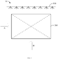
- FIG. 1 schematically shows an application scene of a cooling apparatus according to an embodiment of the present disclosure.
- the application scene 10 includes a sprayer 100 and a cooling apparatus 200.
- the sprayer 100 includes, for example, a spray head for spraying a spray liquid.
- the cooling apparatus 200 includes, for example, an air-to-air heat exchanger.
- a fluid to be cooled enters the cooling apparatus 200 in a direction A.
- the fluid to be cooled may be, for example, indoor hot air.
- the fluid to be cooled may be hot air from a data center.
- the data center may be used for transmission of data under application scenes such as cloud computing, cloud services, etc..
- a cooling medium enters the cooling apparatus 200 in a direction B, and the cooling medium includes, for example, a cold air from the external environment. Heat exchange is performed between the cooling medium and the fluid to be cooled in the cooling apparatus 200, so as to achieve a cooling treatment of the fluid to be cooled with the cooling medium.
- the cooled fluid may return to the data center to take away heat generated in the data center.
- the sprayer 100 may, for example, spray the spray liquid to the cooling apparatus 200, so as to cool the cooling apparatus 200 through the spray liquid.
- FIG. 2 schematically shows an application scene of a cooling apparatus according to another embodiment of the present disclosure.
- the cooling apparatus 200 includes, for example, a plurality of first fluid channels and a plurality of second fluid channels.
- a fluid to be cooled passes through a first fluid channel, and a flow direction of the fluid to be cooled may be, for example, a direction A.
- a cooling medium passes through a second fluid channel, and a flow direction of the cooling medium may be a direction B.
- the first fluid channel and the second fluid channel are independent of each other. That is, the fluid to be cooled in the first fluid channel does not mix with the cooling medium in the second fluid channel.
- the spray liquid may pass through a second fluid channel, and cool a cooling medium in the second fluid channel.
- the spray liquid may fall into a bottom of the cooling apparatus 200 after passing through the second fluid channel from up to down.
- the spray liquid at the bottom may be pumped into the sprayer 100 by a water pump, so as to be sprayed out again.
- the cooling medium may be outside air
- the spray liquid may be a liquid. Since the spray liquid mixes with the cooling medium, impurities in the outside air enters into the spray liquid, which may cause a nozzle of the sprayer to be easily blocked, and the sprayed spray liquid may be uneven, thereby decreasing a cooling effect of the sprayer on the cooling apparatus.
- the cooling apparatuses shown in FIG. 1 and FIG. 2 have a problem of poor cooling effect.
- the embodiments of the present disclosure provide an optimized cooling apparatus.
- the cooling apparatus includes: a main body, a plurality of first fluid channels, at least one second fluid channel, and a spacer.
- the plurality of first fluid channels are provided in the main body.
- the at least one second fluid channel is provided in the main body.
- Each second fluid channel is provided between two adjacent first fluid channels of the plurality of first fluid channels, and adjoins the two adjacent first fluid channels.
- the spacer is provided in each second fluid channel, and is used to divide each second fluid channel into a plurality of sub-channels.
- FIG. 3 schematically shows a schematic diagram of a cooling apparatus according to an embodiment of the present disclosure.
- the cooling apparatus 200 includes: a main body 210, a plurality of first fluid channels, at least one second fluid channel, and a spacer 240.
- the plurality of first fluid channels and the at least one second fluid channel are provided in, for example, the main body 210.
- Each second fluid channel is provided between two adjacent first fluid channels of the plurality of first fluid channels, and adjoins the two adjacent first fluid channels.
- the first fluid channels and the second fluid channels are arranged in sequence.
- the "adjoin" includes a contact or a connection.
- the plurality of first fluid channels includes, for example, a first fluid channel 220A, a first fluid channel 220B, and a first fluid channel 220C.
- the at least one second fluid channel includes, for example, a second fluid channel 230A and a second fluid channel 230B. It should be understood that a second fluid channel is provided between two adjacent first fluid channels, for example, the second fluid channel 230A is provided between two adjacent first fluid channels 220A and 220B.
- the number of the second fluid channel according to an embodiment of the present disclosure is, for example, one.
- the spacer 240 is, for example, provided in each second fluid channel.
- the spacer 240 is used to divide each second fluid channel into a plurality of sub-channels.
- the fluid to be cooled may pass through each first fluid channel.
- the cooling medium may pass through each second fluid channel, and the cooling medium is used to cool the fluid to be cooled.
- the cooling medium includes a liquid or a gas.
- the cooling medium may pass through each sub-channel of the second fluid channel.
- liquids may pass through some of the plurality of sub-channels, and gases may pass through others of the plurality of sub-channels.
- the liquids or the gases may be used to cool fluids to be cooled in the first fluid channels. Heat may be exchanged between the liquids and the gases in different sub-channels, so as to cool the liquids by using the gases, or cool the gases by using the liquids.
- the second fluid channel is generally used to cool a fluid to be cooled in a first fluid channel by using a gas.
- the cooling efficiency by using the gas is relatively low. Therefore, in the embodiments of the present disclosure, the second fluid channel is divided into a plurality of sub-channels by using the spacer, and a liquid and a gas may pass through different sub-channels. The liquid and the gas passing through the plurality of sub-channels may be used to cool fluids to be cooled in the first fluid channels, thereby improving the cooling effect on the fluids to be cooled.
- the sprayer is generally used to spray the spray liquid to the cooling apparatus so as to cool a fluid to be cooled.
- the nozzle of the sprayer may be easily blocked.
- the spacer is used to divide the second fluid channel into a plurality of sub-channels. Instead of spraying the spray liquid for cooling by using an external sprayer, some of the plurality of sub-channels are used for cooling the fluids to be cooled through liquids, thereby avoiding the problem that the impurities in the spray liquid may block the nozzle of the sprayer.
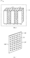
- FIG. 4 schematically shows a schematic diagram of a spacer according to an embodiment of the present disclosure.
- the spacer 240 includes, for example, a through hole 241. Any two adjacent sub-channels of the plurality of sub-channels communicate with each other through the through hole 241. The cooling mediums in different sub-channels may contact each other through the through hole for heat exchange.
- the spacer includes, for example, a first surface 242 and a second surface 243. Each through hole passes through, for example, the first surface 242 and the second surface 243.
- the spacer 240 may be, for example, a mesh screening. The mesh screening may cause a liquid passing through a sub-channel to disperse and flow, and the fluid to be cooled may be fully cooled by the dispersed liquid.
- heat may be exchanged between the liquid and the gas in different sub-channels.
- a liquid in a sub-channel cools a fluid to be cooled in a first fluid channel
- a temperature of the liquid in the sub-channel increases, while a gas in another sub-channel may be used to cool the liquid, so that the cooling effect of the liquid improves, thereby ensuring the cooling effect of the liquid on the fluid to be cooled.
- the spacer is provided between the sub-channel through which the liquid passes and the sub-channel through which the gas passes.
- the spacer is provided with the through hole communicating the plurality of sub-channels, so that the liquid and the gas in different sub-channels may be in contact with each other, thereby improving the heat exchange effect of the liquid and the gas in different sub-channels.
- FIG. 5 schematically shows a schematic diagram of a cooling apparatus according to another embodiment of the present disclosure.
- the cooling apparatus 200 includes: a main body 210, a plurality of first fluid channels, at least one second fluid channel, and a plurality of spacers.
- two spacers are provided in each second fluid channel, and are used to divide the second fluid channel into three sub-channels.
- a spacer 240A and a spacer 240B divide the second fluid channel 230A into three sub-channels.
- the three sub-channels include, for example, a first sub-channel 231, a second sub-channel 232 and a third sub-channel 233.
- the second fluid channel 230A adjoins, for example, two adjacent first fluid channels.
- the two adjacent first fluid channels include, for example, the first fluid channel 220A and the first fluid channel 220B.
- the first sub-channel 231 adjoins, for example, one of the two adjacent first fluid channels.
- the first sub-channel 231 adjoins the first fluid channel 220A.
- the second sub-channel 232 adjoins, for example, the other one of the two adjacent first fluid channels.
- the second sub-channel 232 adjoins the first fluid channel 220B.
- the third sub-channel 233 is, for example, provided between the first sub-channel 231 and the second sub-channel 232.
- cooling mediums may pass through, for example, the first sub-channel 231, the second sub-channel 232 and the third sub-channel 233, so that the cooling mediums are used to cool the fluids to be cooled in the first fluid channels.
- the cooling mediums may include a liquid or a gas.
- the first sub-channel 231 and the second sub-channel 232 may be used, for example, for liquids to pass through. Since the cooling effect of the liquid is relatively good, the first sub-channel 231 and the second sub-channel 232 adjoining the first fluid channels are used for liquids to pass through, so that the liquids may be used to cool the fluids to be cooled in the first fluid channels, thereby improving the cooling efficiency and the cooling effect.
- the third sub-channel 233 may be used, for example, for a gas to pass through.
- the gas may be used to cool the liquid in the first sub-channel 231 and the liquid in the second sub-channel 232.
- the first sub-channel 231 and the third sub-channel 233 are separated by the spacer 240A provided with a through hole, and the second sub-channel 232 and the third sub-channel 233 are separated by the spacer 240B provided with a through hole. Therefore, the gas may be in contact with the liquids through the through holes for heat exchange, thereby improving the cooling effect of the liquids, and further improving the cooling effect of the liquids on the fluids to be cooled.
- any one or more of the first sub-channel 231 and the second sub-channel 232 includes a curved structure.
- the first sub-channel 231 and the second sub-channel 232 may be provided as curved return channels.
- the first sub-channel 231 and the second sub-channel 232 may include curved grooves inside.
- the curved structure may cause a contact area between the liquid and the first fluid channel to increase, thereby improving the cooling efficiency of the liquid on the fluid to be cooled in the first fluid channel.
- the curved structure may cause a flow speed of the liquid to reduce, thereby increasing a cooling time of the liquid on the fluid to be cooled in the first fluid channel, and improving the cooling efficiency.
- the curved structure may also cause the liquid to form an evenly distributed water film in the channel, thereby improving the cooling effect.
- no liquid passes through the first sub-channel 231 and the second sub-channel 232, and a gas may pass through the third sub-channel 233.
- the gas in the third sub-channel 233 may enter the first sub-channel 231 and the second sub-channel 232 via the through hole in the spacer, so that the gas may be in contact with the first fluid channel, thereby cooling the fluid to be cooled in the first fluid channel by using the gas.
- FIG. 6 schematically shows a schematic diagram of a cooling apparatus according to another embodiment of the present disclosure.
- the cooling apparatus 200 includes: a main body 210, a plurality of first fluid channels, at least one second fluid channel, and a spacer.
- the plurality of first fluid channels include, for example, a first fluid channel 220A, a first fluid channel 220B, and a first fluid channel 220C.
- the at least one second fluid channel includes, for example, a second fluid channel 230A and a second fluid channel 230B.
- one spacer is provided in each second fluid channel and used to divide the second fluid channel into two sub-channels.
- a spacer 240C divides the second fluid channel 230A into two sub-channels.
- the two sub-channels include, for example, a fourth sub-channel 234 and a fifth sub-channel 235.
- the second fluid channel 230A adjoins, for example, two adjacent first fluid channels.
- the two adjacent first fluid channels include, for example, the first fluid channel 220A and the first fluid channel 220B.
- the fourth sub-channel 234 adjoins, for example, one of the two adjacent first fluid channels.
- the fourth sub-channel 234 adjoins the first fluid channel 220A.
- the fifth sub-channel 235 adjoins, for example, the other one of the two adjacent first fluid channels.
- the fifth sub-channel 235 adjoins the first fluid channel 220B.
- the fourth sub-channel 234 and the fifth sub-channel 235 are used, for example, for cooling mediums to pass through, so that the cooling mediums are used to cool the fluids to be cooled in the first fluid channels.
- the cooling mediums may include a liquid or a gas.
- the fourth sub-channel 234 may be used, for example, for a liquid to pass through, and the liquid may be used to cool a fluid to be cooled in the first fluid channel 220A.
- the fifth sub-channel 235 may be used, for example, for a gas to pass through, and the gas may be used to cool a fluid to be cooled in the first fluid channel 220B. Since the cooling effect of the liquid is relatively good, a temperature of the liquid in the fourth sub-channel 234 is generally higher.
- the gas in the fifth sub-channel 235 may be further used to cool the liquid in the fourth sub-channel 234.
- the fourth sub-channel 234 and the fifth sub-channel 235 are separated by a spacer provided with a through hole.
- the gas may be in contact with the liquid through the through hole for heat exchange, thereby improving the cooling effect of the liquid, and further improving the cooling effect of the liquid on the fluid to be cooled. Both the liquid and the gas are used to cool the fluid to be cooled, thereby improving the cooling efficiency and the cooling effect.
- the fourth sub-channel 234 used for the liquid to pass through includes a curved structure.
- the fourth sub-channel 234 may be provided as a curved return channel.
- the fourth sub-channel 234 may include a curved groove inside.
- the curved structure may cause a contact area between the liquid and the first fluid channel to improve, thereby improving the cooling efficiency of the liquid on the fluid to be cooled in the first fluid channel.
- the curved structure may reduce a flow speed of the liquid, thereby increasing a cooling time of the liquid on the fluid to be cooled in the first fluid channel, and improving the cooling efficiency.
- the curved structure may also cause the liquid to form an evenly distributed water film in the channel, thereby improving the cooling effect.
- no liquid passes through the fourth sub-channel 234, and a gas may pass through the fifth sub-channel 235.
- the gas in the fifth sub-channel 235 may enter the fourth sub-channel 234 via the through hole in the spacer, so that the gas may be in contact with the first fluid channel 220A, thereby cooling the fluid to be cooled in the first fluid channel 220A and the fluid to be cooled in the first fluid channel 220B by using the gas.
- FIG. 7 schematically shows a schematic diagram of a direction of a channel according to an embodiment of the present disclosure.
- the cooling apparatus 200 includes: a main body 210, a plurality of first fluid channels, at least one second fluid channel, and a spacer.
- the plurality of first fluid channels include, for example, a first fluid channel 220A, a first fluid channel 220B, and a first fluid channel 220C.
- the at least one second fluid channel includes, for example, a second fluid channel 230A and a second fluid channel 230B.
- each first fluid channel includes a first inlet and a first outlet, and a direction from the first inlet to the first outlet is a first direction.
- the first direction is direction A.
- each second fluid channel includes a second inlet and a second outlet, and a direction from the second inlet to the second outlet is a second direction.
- the second direction is direction B.
- the second direction is different from the first direction.
- the first direction is a horizontal direction
- a second direction is a vertical direction.
- a second inlet of the sub-channel is located, for example, in an upper part, and a second outlet of the sub-channel is located, for example, in an lower part, so that when the liquid passes through the sub-channel, the liquid may flow from up to down under gravity.
- a second inlet of the sub-channel is located, for example, in an lower part, and a second outlet of the sub-channel is located, for example, in an upper part, so that when the gas passes through the sub-channel, the fluid may flow from bottom to up. There may be a more fully contact between the gas flowing bottom-to-up and the liquid, thereby improving a heat exchange effect between the gas and the liquid.
- FIG. 8 schematically shows a schematic diagram of a distribution of a spacer according to an embodiment of the present disclosure.
- the embodiment of the present disclosure provides a first fluid channel 220B, a second fluid channel 230A, and a second fluid channel 230B.
- a spacer 240C is used, for example, to divide the second fluid channel 230A into a plurality of sub-channels
- a spacer 240D is used, for example, to divide the second fluid channel 230B into a plurality of sub-channels.
- a flow direction of the fluid to be cooled in the first fluid channel 220B is, for example, direction A.
- a flow direction of the liquid in the sub-channel is, for example, direction B 1 .
- a flow direction of the gas in the sub-channel is, for example, direction B 2 .
- FIG. 9 schematically shows a schematic diagram of a cooling apparatus according to an embodiment of the present disclosure.
- the cooling apparatus includes, for example, a main body, a plurality of first fluid channels, at least one second fluid channel, and a plurality of spacers.
- first fluid channel and the second fluid channel may be provided in various shapes. Taking the plurality of first fluid channels including a first fluid channel 220A and a first fluid channel 220B, and the at least one second fluid channel including, for example, the second fluid channel 230A as an example, for description.
- a spacer 240A and a spacer 240B divide the second fluid channel 230A into three sub-channels.
- the three sub-channels include, for example, a first sub-channel 231, a second sub-channel 232 and a third sub-channel 233.
- the first sub-channel 231 and the second sub-channel 232 may be used, for example, for liquids to pass through. Since the cooling effect of the liquid is relative good, the first sub-channel 231 and the second sub-channel 232 adjoining the first fluid channels are provided for the flow of the liquids, so that the liquids may be used to cool the fluids to be cooled in the first fluid channels, thereby improving the cooling efficiency and the cooling effect.
- the third sub-channel 233 may be used, for example, for a gas to pass through.
- the gas may be used to cool the liquid in the first sub-channel 231 and the liquid in the second sub-channel 232.
- the first sub-channel 231 and the third sub-channel 233 are separated by a spacer 240A provided with a through hole, and the second sub-channel 232 and the third sub-channel 233 are separated by a spacer 240B provided with a through hole. Therefore, the gas may contact the liquids via the through hole for heat exchange, which may improve the cooling effect of the liquids, and further improving the cooling effect of the liquids on the fluids to be cooled.
- the present disclosure provides a cooling method implemented by the cooling apparatus 200 according to above-mentioned embodiments of the present disclosure.
- a gas is introduced into the third sub-channel 233, and no liquid or gas is introduced into the first sub-channel 231 and the second sub-channel 232.
- the present disclosure provides a cooling method implemented by the cooling apparatus 200 according to above-mentioned embodiments of the present disclosure.
- a gas is introduced into the third sub-channel 233 and liquids are introduced into the first sub-channel 231 and the second sub-channel 232.
Landscapes
- Engineering & Computer Science (AREA)
- Physics & Mathematics (AREA)
- Thermal Sciences (AREA)
- Microelectronics & Electronic Packaging (AREA)
- General Engineering & Computer Science (AREA)
- Mechanical Engineering (AREA)
- Computer Hardware Design (AREA)
- Cooling Or The Like Of Electrical Apparatus (AREA)
- Heat-Exchange Devices With Radiators And Conduit Assemblies (AREA)
Abstract
Description
- The present disclosure relates to the field of data center, specifically relates to the technical field of refrigeration device, and in particular to a cooling apparatus and method.
- In the related art, a cooling apparatus is generally used to cool a fluid to be cooled, and the cooling apparatus includes, for example, an air-to-air heat exchanger. However, a cooling efficiency of the cooling apparatus in the related art is relatively low, and the cooling effect is not good. In addition, when spraying a spray liquid to the cooling apparatus through a sprayer to cool the cooling apparatus, requirements for the spray liquid are relatively high. When the spray liquid is mixed with various impurities, the sprayer will be blocked, thereby decreasing a cooling effect on the cooling apparatus.
- According to the embodiments of the present disclosure, a cooling apparatus is provided, including: a main body; a plurality of first fluid channels provided in the main body; at least one second fluid channel provided in the main body, wherein each second fluid channel is provided between two adjacent first fluid channels of the plurality of first fluid channels, and adjoins the two adjacent first fluid channels; and a spacer provided in each second fluid channel, wherein the spacer is configured to divide each second fluid channel into a plurality of sub-channels.
- According to the embodiments of the present disclosure, a cooling method implemented by a cooling apparatus is provided, wherein the cooling apparatus includes: a main body; a plurality of first fluid channels provided in the main body; at least one second fluid channel provided in the main body, each second fluid channel of the at least one second fluid channel being provided between two adjacent first fluid channels of the plurality of first fluid channels, and adjoining the two adjacent first fluid channels; and a spacer provided in each second fluid channel, the spacer being configured to divide each second fluid channel into a plurality of sub-channels; the method includes: introducing a fluid into at least one of the plurality of sub-channels.
- It should be understood that, the content described in this section is not intended to characterize the key or vital features of the embodiments of the present disclosure, and is not used to limit the scope of the present disclosure. With the following description, other features of the present disclosure will become easily understood.
- The accompanying drawings are used for a better understanding of the present disclosure, rather than limiting the present disclosure, in which:
-
FIG. 1 schematically shows an application scene of a cooling apparatus according to an embodiment of the present disclosure; -
FIG. 2 schematically shows an application scene of a cooling apparatus according to another embodiment of the present disclosure; -
FIG. 3 schematically shows a schematic diagram of a cooling apparatus according to an embodiment of the present disclosure; -
FIG. 4 schematically shows a schematic diagram of a spacer according to an embodiment of the present disclosure; -
FIG. 5 schematically shows a schematic diagram of a cooling apparatus according to another embodiment of the present disclosure; -
FIG. 6 schematically shows a schematic diagram of a cooling apparatus according to another embodiment of the present disclosure; -
FIG. 7 schematically shows a schematic diagram of a direction of a channel according to an embodiment of the present disclosure; -
FIG. 8 schematically shows a schematic diagram of a distribution of a spacer according to an embodiment of the present disclosure; and -
FIG. 9 schematically shows a schematic diagram of a cooling apparatus according to another embodiment of the present disclosure - In the following, exemplary embodiments of the present disclosure will be described with reference to the accompanying drawings, wherein various details of the present disclosure are included for understanding, and they should be considered as merely illustrative. Therefore, those of ordinary skilled in the art should recognize that various changes and modifications may be made to the embodiments described herein, without departing from the scope and the spirit of the present disclosure. Also, for clarity and conciseness, descriptions of well-known functions and structures are omitted in the following descriptions.
- The terms used herein are for describing specific embodiments only, and is not intended to limit the present disclosure. The terms "including", "comprising", etc. used herein indicate the presence of features, steps, operations and/or components, but do not exclude the presence or addition of one or more other features, steps, operations or components.
- Unless otherwise defined, all the terms (including the scientific terms and technical terms) used herein have the meanings generally understood by those of ordinary skilled in the art. It should be noted that, the terms used herein should be construed as having the meanings consistent with the context of the present disclosure, and should be explained in an idealized or overly rigid manner.
-
FIG. 1 schematically shows an application scene of a cooling apparatus according to an embodiment of the present disclosure. - As shown in
FIG. 1 , theapplication scene 10 according to the embodiment of the present disclosure includes asprayer 100 and acooling apparatus 200. Thesprayer 100 includes, for example, a spray head for spraying a spray liquid. Thecooling apparatus 200 includes, for example, an air-to-air heat exchanger. - In an example, a fluid to be cooled enters the
cooling apparatus 200 in a direction A. The fluid to be cooled may be, for example, indoor hot air. For example, the fluid to be cooled may be hot air from a data center. The data center may be used for transmission of data under application scenes such as cloud computing, cloud services, etc.. - A cooling medium enters the
cooling apparatus 200 in a direction B, and the cooling medium includes, for example, a cold air from the external environment. Heat exchange is performed between the cooling medium and the fluid to be cooled in thecooling apparatus 200, so as to achieve a cooling treatment of the fluid to be cooled with the cooling medium. The cooled fluid may return to the data center to take away heat generated in the data center. - In an example, the
sprayer 100 may, for example, spray the spray liquid to thecooling apparatus 200, so as to cool thecooling apparatus 200 through the spray liquid. -
FIG. 2 schematically shows an application scene of a cooling apparatus according to another embodiment of the present disclosure. - As shown in
FIG. 2 , thecooling apparatus 200 includes, for example, a plurality of first fluid channels and a plurality of second fluid channels. A fluid to be cooled passes through a first fluid channel, and a flow direction of the fluid to be cooled may be, for example, a direction A. A cooling medium passes through a second fluid channel, and a flow direction of the cooling medium may be a direction B. The first fluid channel and the second fluid channel are independent of each other. That is, the fluid to be cooled in the first fluid channel does not mix with the cooling medium in the second fluid channel. - When the
sprayer 100 sprays the spray liquid to thecooling apparatus 200, the spray liquid may pass through a second fluid channel, and cool a cooling medium in the second fluid channel. The spray liquid may fall into a bottom of thecooling apparatus 200 after passing through the second fluid channel from up to down. The spray liquid at the bottom may be pumped into thesprayer 100 by a water pump, so as to be sprayed out again. - In an example, the cooling medium may be outside air, and the spray liquid may be a liquid. Since the spray liquid mixes with the cooling medium, impurities in the outside air enters into the spray liquid, which may cause a nozzle of the sprayer to be easily blocked, and the sprayed spray liquid may be uneven, thereby decreasing a cooling effect of the sprayer on the cooling apparatus.
- The cooling apparatuses shown in
FIG. 1 andFIG. 2 have a problem of poor cooling effect. In view of this, the embodiments of the present disclosure provide an optimized cooling apparatus. The cooling apparatus includes: a main body, a plurality of first fluid channels, at least one second fluid channel, and a spacer. The plurality of first fluid channels are provided in the main body. The at least one second fluid channel is provided in the main body. Each second fluid channel is provided between two adjacent first fluid channels of the plurality of first fluid channels, and adjoins the two adjacent first fluid channels. The spacer is provided in each second fluid channel, and is used to divide each second fluid channel into a plurality of sub-channels. The cooling apparatus according to the embodiments of the present disclosure will be described with reference toFIGS. 3 to 9 . -
FIG. 3 schematically shows a schematic diagram of a cooling apparatus according to an embodiment of the present disclosure. - As shown in
FIG. 3 , thecooling apparatus 200 according to the embodiment of the present disclosure includes: amain body 210, a plurality of first fluid channels, at least one second fluid channel, and aspacer 240. - The plurality of first fluid channels and the at least one second fluid channel are provided in, for example, the
main body 210. Each second fluid channel is provided between two adjacent first fluid channels of the plurality of first fluid channels, and adjoins the two adjacent first fluid channels. The first fluid channels and the second fluid channels are arranged in sequence. The "adjoin" includes a contact or a connection. - In an example, the plurality of first fluid channels includes, for example, a first
fluid channel 220A, a firstfluid channel 220B, and a firstfluid channel 220C. The at least one second fluid channel includes, for example, a secondfluid channel 230A and a secondfluid channel 230B. It should be understood that a second fluid channel is provided between two adjacent first fluid channels, for example, the secondfluid channel 230A is provided between two adjacent firstfluid channels - The
spacer 240 is, for example, provided in each second fluid channel. Thespacer 240 is used to divide each second fluid channel into a plurality of sub-channels. - For example, the fluid to be cooled may pass through each first fluid channel. For example, the cooling medium may pass through each second fluid channel, and the cooling medium is used to cool the fluid to be cooled. The cooling medium includes a liquid or a gas. The cooling medium may pass through each sub-channel of the second fluid channel.
- For example, for the plurality of sub-channels of each second fluid channel, liquids may pass through some of the plurality of sub-channels, and gases may pass through others of the plurality of sub-channels. The liquids or the gases may be used to cool fluids to be cooled in the first fluid channels. Heat may be exchanged between the liquids and the gases in different sub-channels, so as to cool the liquids by using the gases, or cool the gases by using the liquids.
- It should be understood that in the related art, the second fluid channel is generally used to cool a fluid to be cooled in a first fluid channel by using a gas. However, the cooling efficiency by using the gas only is relatively low. Therefore, in the embodiments of the present disclosure, the second fluid channel is divided into a plurality of sub-channels by using the spacer, and a liquid and a gas may pass through different sub-channels. The liquid and the gas passing through the plurality of sub-channels may be used to cool fluids to be cooled in the first fluid channels, thereby improving the cooling effect on the fluids to be cooled.
- In addition, in the related art, the sprayer is generally used to spray the spray liquid to the cooling apparatus so as to cool a fluid to be cooled. However, since there may be impurities in the spray liquid, the nozzle of the sprayer may be easily blocked. In the embodiments of the present disclosure, the spacer is used to divide the second fluid channel into a plurality of sub-channels. Instead of spraying the spray liquid for cooling by using an external sprayer, some of the plurality of sub-channels are used for cooling the fluids to be cooled through liquids, thereby avoiding the problem that the impurities in the spray liquid may block the nozzle of the sprayer.
-
FIG. 4 schematically shows a schematic diagram of a spacer according to an embodiment of the present disclosure. - As shown in
FIG. 4 , thespacer 240 according to the embodiment of the present disclosure includes, for example, a throughhole 241. Any two adjacent sub-channels of the plurality of sub-channels communicate with each other through the throughhole 241. The cooling mediums in different sub-channels may contact each other through the through hole for heat exchange. - In an example, the spacer includes, for example, a
first surface 242 and asecond surface 243. Each through hole passes through, for example, thefirst surface 242 and thesecond surface 243. In an example, thespacer 240 may be, for example, a mesh screening. The mesh screening may cause a liquid passing through a sub-channel to disperse and flow, and the fluid to be cooled may be fully cooled by the dispersed liquid. - It should be understood that, heat may be exchanged between the liquid and the gas in different sub-channels. After a liquid in a sub-channel cools a fluid to be cooled in a first fluid channel, a temperature of the liquid in the sub-channel increases, while a gas in another sub-channel may be used to cool the liquid, so that the cooling effect of the liquid improves, thereby ensuring the cooling effect of the liquid on the fluid to be cooled. The spacer is provided between the sub-channel through which the liquid passes and the sub-channel through which the gas passes. The spacer is provided with the through hole communicating the plurality of sub-channels, so that the liquid and the gas in different sub-channels may be in contact with each other, thereby improving the heat exchange effect of the liquid and the gas in different sub-channels.
-
FIG. 5 schematically shows a schematic diagram of a cooling apparatus according to another embodiment of the present disclosure. - As shown in
FIG. 5 , thecooling apparatus 200 according to the embodiment of the present disclosure includes: amain body 210, a plurality of first fluid channels, at least one second fluid channel, and a plurality of spacers. - The plurality of first fluid channels include, for example, a first
fluid channel 220A, a firstfluid channel 220B, and a firstfluid channel 220C. The at least one second fluid channel includes, for example, a secondfluid channel 230A and a secondfluid channel 230B. - In an example, two spacers are provided in each second fluid channel, and are used to divide the second fluid channel into three sub-channels. Taking the second
fluid channel 230A as an example, aspacer 240A and aspacer 240B divide the secondfluid channel 230A into three sub-channels. The three sub-channels include, for example, afirst sub-channel 231, asecond sub-channel 232 and athird sub-channel 233. - In an example, the second
fluid channel 230A adjoins, for example, two adjacent first fluid channels. The two adjacent first fluid channels include, for example, the firstfluid channel 220A and the firstfluid channel 220B. - The
first sub-channel 231 adjoins, for example, one of the two adjacent first fluid channels. For example, thefirst sub-channel 231 adjoins the firstfluid channel 220A. - The
second sub-channel 232 adjoins, for example, the other one of the two adjacent first fluid channels. For example, thesecond sub-channel 232 adjoins the firstfluid channel 220B. - The
third sub-channel 233 is, for example, provided between thefirst sub-channel 231 and thesecond sub-channel 232. - In an example, cooling mediums may pass through, for example, the
first sub-channel 231, thesecond sub-channel 232 and thethird sub-channel 233, so that the cooling mediums are used to cool the fluids to be cooled in the first fluid channels. The cooling mediums may include a liquid or a gas. - In an example, the
first sub-channel 231 and thesecond sub-channel 232 may be used, for example, for liquids to pass through. Since the cooling effect of the liquid is relatively good, thefirst sub-channel 231 and thesecond sub-channel 232 adjoining the first fluid channels are used for liquids to pass through, so that the liquids may be used to cool the fluids to be cooled in the first fluid channels, thereby improving the cooling efficiency and the cooling effect. - In an example, the
third sub-channel 233 may be used, for example, for a gas to pass through. The gas may be used to cool the liquid in thefirst sub-channel 231 and the liquid in thesecond sub-channel 232. Thefirst sub-channel 231 and thethird sub-channel 233 are separated by thespacer 240A provided with a through hole, and thesecond sub-channel 232 and thethird sub-channel 233 are separated by thespacer 240B provided with a through hole. Therefore, the gas may be in contact with the liquids through the through holes for heat exchange, thereby improving the cooling effect of the liquids, and further improving the cooling effect of the liquids on the fluids to be cooled. - In an example, any one or more of the
first sub-channel 231 and thesecond sub-channel 232 includes a curved structure. For example, thefirst sub-channel 231 and thesecond sub-channel 232 may be provided as curved return channels. Alternatively, thefirst sub-channel 231 and thesecond sub-channel 232 may include curved grooves inside. It should be understood that the curved structure may cause a contact area between the liquid and the first fluid channel to increase, thereby improving the cooling efficiency of the liquid on the fluid to be cooled in the first fluid channel. In addition, the curved structure may cause a flow speed of the liquid to reduce, thereby increasing a cooling time of the liquid on the fluid to be cooled in the first fluid channel, and improving the cooling efficiency. The curved structure may also cause the liquid to form an evenly distributed water film in the channel, thereby improving the cooling effect. - In another example, no liquid passes through the
first sub-channel 231 and thesecond sub-channel 232, and a gas may pass through thethird sub-channel 233. The gas in thethird sub-channel 233 may enter thefirst sub-channel 231 and thesecond sub-channel 232 via the through hole in the spacer, so that the gas may be in contact with the first fluid channel, thereby cooling the fluid to be cooled in the first fluid channel by using the gas. -
FIG. 6 schematically shows a schematic diagram of a cooling apparatus according to another embodiment of the present disclosure. - As shown in
FIG. 6 , thecooling apparatus 200 according to the embodiment of the present disclosure includes: amain body 210, a plurality of first fluid channels, at least one second fluid channel, and a spacer. - The plurality of first fluid channels include, for example, a first
fluid channel 220A, a firstfluid channel 220B, and a firstfluid channel 220C. The at least one second fluid channel includes, for example, a secondfluid channel 230A and a secondfluid channel 230B. - In an example, one spacer is provided in each second fluid channel and used to divide the second fluid channel into two sub-channels. Taking the second
fluid channel 230A as an example, aspacer 240C divides the secondfluid channel 230A into two sub-channels. The two sub-channels include, for example, afourth sub-channel 234 and afifth sub-channel 235. - In an example, the second
fluid channel 230A adjoins, for example, two adjacent first fluid channels. The two adjacent first fluid channels include, for example, the firstfluid channel 220A and the firstfluid channel 220B. - The
fourth sub-channel 234 adjoins, for example, one of the two adjacent first fluid channels. For example, thefourth sub-channel 234 adjoins the firstfluid channel 220A. - The
fifth sub-channel 235 adjoins, for example, the other one of the two adjacent first fluid channels. For example, thefifth sub-channel 235 adjoins the firstfluid channel 220B. - In an example, the
fourth sub-channel 234 and thefifth sub-channel 235 are used, for example, for cooling mediums to pass through, so that the cooling mediums are used to cool the fluids to be cooled in the first fluid channels. The cooling mediums may include a liquid or a gas. - The
fourth sub-channel 234 may be used, for example, for a liquid to pass through, and the liquid may be used to cool a fluid to be cooled in the firstfluid channel 220A. Thefifth sub-channel 235 may be used, for example, for a gas to pass through, and the gas may be used to cool a fluid to be cooled in the firstfluid channel 220B. Since the cooling effect of the liquid is relatively good, a temperature of the liquid in thefourth sub-channel 234 is generally higher. In addition to cooling the fluid to be cooled in the firstfluid channel 220B, the gas in thefifth sub-channel 235 may be further used to cool the liquid in thefourth sub-channel 234. For example, thefourth sub-channel 234 and thefifth sub-channel 235 are separated by a spacer provided with a through hole. The gas may be in contact with the liquid through the through hole for heat exchange, thereby improving the cooling effect of the liquid, and further improving the cooling effect of the liquid on the fluid to be cooled. Both the liquid and the gas are used to cool the fluid to be cooled, thereby improving the cooling efficiency and the cooling effect. - In an example, the
fourth sub-channel 234 used for the liquid to pass through includes a curved structure. For example, thefourth sub-channel 234 may be provided as a curved return channel. Alternatively, thefourth sub-channel 234 may include a curved groove inside. It should be understood that the curved structure may cause a contact area between the liquid and the first fluid channel to improve, thereby improving the cooling efficiency of the liquid on the fluid to be cooled in the first fluid channel. In addition, the curved structure may reduce a flow speed of the liquid, thereby increasing a cooling time of the liquid on the fluid to be cooled in the first fluid channel, and improving the cooling efficiency. The curved structure may also cause the liquid to form an evenly distributed water film in the channel, thereby improving the cooling effect. - In another example, no liquid passes through the
fourth sub-channel 234, and a gas may pass through thefifth sub-channel 235. The gas in thefifth sub-channel 235 may enter thefourth sub-channel 234 via the through hole in the spacer, so that the gas may be in contact with the firstfluid channel 220A, thereby cooling the fluid to be cooled in the firstfluid channel 220A and the fluid to be cooled in the firstfluid channel 220B by using the gas. -
FIG. 7 schematically shows a schematic diagram of a direction of a channel according to an embodiment of the present disclosure. - As shown in
FIG. 7 , thecooling apparatus 200 according to the embodiment of the present disclosure includes: amain body 210, a plurality of first fluid channels, at least one second fluid channel, and a spacer. - The plurality of first fluid channels include, for example, a first
fluid channel 220A, a firstfluid channel 220B, and a firstfluid channel 220C. The at least one second fluid channel includes, for example, a secondfluid channel 230A and a secondfluid channel 230B. - In an example, each first fluid channel includes a first inlet and a first outlet, and a direction from the first inlet to the first outlet is a first direction. Taking the first
fluid channel 220A as an example, the first direction is direction A. - In an example, each second fluid channel includes a second inlet and a second outlet, and a direction from the second inlet to the second outlet is a second direction. Taking the second
fluid channel 230A as an example, the second direction is direction B. - The second direction is different from the first direction. For example, the first direction is a horizontal direction, and a second direction is a vertical direction.
- In an example, for a sub-channel used for a liquid to pass through in the second
fluid channel 230A, a second inlet of the sub-channel is located, for example, in an upper part, and a second outlet of the sub-channel is located, for example, in an lower part, so that when the liquid passes through the sub-channel, the liquid may flow from up to down under gravity. - In an example, for a sub-channel used for a gas to pass through in the second
fluid channel 230A, a second inlet of the sub-channel is located, for example, in an lower part, and a second outlet of the sub-channel is located, for example, in an upper part, so that when the gas passes through the sub-channel, the fluid may flow from bottom to up. There may be a more fully contact between the gas flowing bottom-to-up and the liquid, thereby improving a heat exchange effect between the gas and the liquid. -
FIG. 8 schematically shows a schematic diagram of a distribution of a spacer according to an embodiment of the present disclosure. - As shown in
FIG. 8 , the embodiment of the present disclosure provides a firstfluid channel 220B, a secondfluid channel 230A, and a secondfluid channel 230B. - A
spacer 240C is used, for example, to divide the secondfluid channel 230A into a plurality of sub-channels, and aspacer 240D is used, for example, to divide the secondfluid channel 230B into a plurality of sub-channels. - A flow direction of the fluid to be cooled in the first
fluid channel 220B is, for example, direction A. For a sub-channel used for a liquid to pass through, a flow direction of the liquid in the sub-channel is, for example, direction B1. For a sub-channel used for a gas to pass through, a flow direction of the gas in the sub-channel is, for example, direction B2. -
FIG. 9 schematically shows a schematic diagram of a cooling apparatus according to an embodiment of the present disclosure. - As shown in
FIG.9 , the cooling apparatus according to the embodiment of the present disclosure includes, for example, a main body, a plurality of first fluid channels, at least one second fluid channel, and a plurality of spacers. - In an example, the first fluid channel and the second fluid channel may be provided in various shapes. Taking the plurality of first fluid channels including a first
fluid channel 220A and a firstfluid channel 220B, and the at least one second fluid channel including, for example, the secondfluid channel 230A as an example, for description. - A
spacer 240A and aspacer 240B divide the secondfluid channel 230A into three sub-channels. The three sub-channels include, for example, afirst sub-channel 231, asecond sub-channel 232 and athird sub-channel 233. - The
first sub-channel 231 and thesecond sub-channel 232 may be used, for example, for liquids to pass through. Since the cooling effect of the liquid is relative good, thefirst sub-channel 231 and thesecond sub-channel 232 adjoining the first fluid channels are provided for the flow of the liquids, so that the liquids may be used to cool the fluids to be cooled in the first fluid channels, thereby improving the cooling efficiency and the cooling effect. - The
third sub-channel 233 may be used, for example, for a gas to pass through. The gas may be used to cool the liquid in thefirst sub-channel 231 and the liquid in thesecond sub-channel 232. Thefirst sub-channel 231 and thethird sub-channel 233 are separated by aspacer 240A provided with a through hole, and thesecond sub-channel 232 and thethird sub-channel 233 are separated by aspacer 240B provided with a through hole. Therefore, the gas may contact the liquids via the through hole for heat exchange, which may improve the cooling effect of the liquids, and further improving the cooling effect of the liquids on the fluids to be cooled. - The present disclosure provides a cooling method implemented by the
cooling apparatus 200 according to above-mentioned embodiments of the present disclosure. In the method, a gas is introduced into thethird sub-channel 233, and no liquid or gas is introduced into thefirst sub-channel 231 and thesecond sub-channel 232. - The present disclosure provides a cooling method implemented by the
cooling apparatus 200 according to above-mentioned embodiments of the present disclosure. In the method, a gas is introduced into thethird sub-channel 233 and liquids are introduced into thefirst sub-channel 231 and thesecond sub-channel 232. - The above-mentioned embodiments do not limit the protection scope of the present disclosure. Those skilled in the art should understand that, various modifications, combinations, sub-combinations and substitutions may be made according to design requirements and other factors. Any modifications, equivalent substitutions and improvements made within the scope and the principle of the present disclosure should all fall within the protection scope of the present disclosure.
Claims (15)
- A cooling apparatus (200), comprising:a main body (210);a plurality of first fluid channels (220A, 220B, 220C) provided in the main body (210);at least one second fluid channel (230A, 230B) provided in the main body (210), each second fluid channel of the at least one second fluid channel (230A, 230B) being provided between two adjacent first fluid channels of the plurality of first fluid channels (220A, 220B, 220C), and adjoining the two adjacent first fluid channels; anda spacer (240A, 240B, 240C) provided in each second fluid channel, the spacer (240A, 240B, 240C) being configured to divide each second fluid channel into a plurality of sub-channels (231, 232, 233, 234, 235).
- The cooling apparatus (200) according to claim 1, wherein the spacer (240A, 240B, 240C) comprises a through hole (241), and any two adjacent sub-channels of the plurality of sub-channels (231, 232, 233, 234, 235) are configured to communicate with each other through the through hole (241).
- The cooling apparatus (200) according to claim 1, wherein two spacers are provided in each second fluid channel, and configured to divide the second fluid channel into three sub-channels.
- The cooling apparatus (200) according to claim 3, wherein the three sub-channels comprise:a first sub-channel (231), wherein the first sub-channel (231) adjoins one first fluid channel of the two adjacent first fluid channels;a second sub-channel (232), wherein the second sub-channel (232) adjoins the other one of the two adjacent first fluid channels; anda third sub-channel (233) provided between the first sub-channel (231) and the second sub-channel (232).
- The cooling apparatus (200) according to claim 4, wherein any one or more of the first sub-channel (231) and the second sub-channel (232) comprises a curved structure.
- The cooling apparatus (200) according to claim 1, wherein one spacer is provided in each second fluid channel, and configured to divide the second fluid channel (230A, 230B) into two sub-channels.
- The cooling apparatus (200) according to claim 6, wherein any one of the two sub-channels comprises a curved structure.
- The cooling apparatus (200) according to claim 1, wherein each first fluid channel comprises a first inlet and a first outlet, and a direction from the first inlet to the first outlet is a first direction (A).
- The cooling apparatus (200) according to claim 8, wherein each second fluid channel comprises a second inlet and a second outlet, a direction from the second inlet to the second outlet is a second direction (B), and the first direction (A) is different from the second direction (B).
- The cooling apparatus (200) according to claim 9, wherein the first direction (A) comprises a horizontal direction, and the second direction (B) comprises a vertical direction.
- The cooling apparatus (200) according to any one of claims 1 to 10, wherein the spacer (240A, 240B, 240C) comprises a mesh screening.
- A cooling method implemented by a cooling apparatus (200), wherein the cooling apparatus comprises:a main body (210);a plurality of first fluid channels (220A, 220B, 220C) provided in the main body (210);at least one second fluid channel (230A, 230B) provided in the main body (210), each second fluid channel of the at least one second fluid channel (230A, 230B) being provided between two adjacent first fluid channels of the plurality of first fluid channels (220A, 220B, 220C), and adjoining the two adjacent first fluid channels; anda spacer (240A, 240B, 240C) provided in each second fluid channel, the spacer (240A, 240B, 240C) being configured to divide each second fluid channel into a plurality of sub-channels (231, 232, 233, 234, 235);the method comprises:
introducing a fluid into at least one of the plurality of sub-channels (231, 232, 233, 234, 235). - The method according to claim 12, wherein two spacers are provided in each second fluid channel, and configured to divide the second fluid channel into three sub-channels;
wherein the three sub-channels comprise:a first sub-channel (231), wherein the first sub-channel (231) adjoins one first fluid channel of the two adjacent first fluid channels;a second sub-channel (232), wherein the second sub-channel (232) adjoins the other one of the two adjacent first fluid channels; anda third sub-channel (233) provided between the first sub-channel (231) and the second sub-channel (232). - The method according to claim 13, wherein the fluid comprises a gas, and the introducing a fluid into at least one of the plurality of sub-channels (231, 232, 233, 234, 235) comprises:
introducing the gas into the third sub-channel (233). - The method according to claim 14, wherein the fluid further comprises a liquid, and the introducing a fluid into at least one of the plurality of sub-channels (231, 232, 233, 234, 235) further comprises:
introducing liquids into the first sub-channel (231) and the second sub-channel (232).
Applications Claiming Priority (1)
| Application Number | Priority Date | Filing Date | Title |
|---|---|---|---|
| CN202110477595.XA CN113163693B (en) | 2021-04-29 | 2021-04-29 | Cooling device |
Publications (2)
| Publication Number | Publication Date |
|---|---|
| EP4025028A2 true EP4025028A2 (en) | 2022-07-06 |
| EP4025028A3 EP4025028A3 (en) | 2022-11-02 |
Family
ID=76872701
Family Applications (1)
| Application Number | Title | Priority Date | Filing Date |
|---|---|---|---|
| EP22170244.2A Withdrawn EP4025028A3 (en) | 2021-04-29 | 2022-04-27 | Cooling apparatus and method |
Country Status (2)
| Country | Link |
|---|---|
| EP (1) | EP4025028A3 (en) |
| CN (1) | CN113163693B (en) |
Family Cites Families (12)
| Publication number | Priority date | Publication date | Assignee | Title |
|---|---|---|---|---|
| US5704763A (en) * | 1990-08-01 | 1998-01-06 | General Electric Company | Shear jet cooling passages for internally cooled machine elements |
| US8191615B2 (en) * | 2006-11-24 | 2012-06-05 | Dana Canada Corporation | Linked heat exchangers having three fluids |
| EP2694899B1 (en) * | 2011-04-01 | 2017-08-02 | Ingersoll-Rand Company | Heat exchanger for a refrigerated air dryer |
| EP2515064B1 (en) * | 2011-04-20 | 2014-06-04 | Senior Uk Limited | Heat exchanger |
| CN203908124U (en) * | 2014-05-27 | 2014-10-29 | 北汽福田汽车股份有限公司 | Vehicle and heat exchange device, condenser assembly and refrigerating system of vehicle |
| US10408511B2 (en) * | 2015-02-25 | 2019-09-10 | Zhejiang Sanhua Automotive Components Co., Ltd. | Heat exchange device |
| US20170003039A1 (en) * | 2015-07-02 | 2017-01-05 | Schneider Electric It Corporation | Cooling system and method having micro-channel coil with countercurrent circuit |
| EP3168561A1 (en) * | 2015-11-11 | 2017-05-17 | Air To Air Sweden AB | A device for exchange of heat and/or mass transfer between fluid flows |
| NL2016901B1 (en) * | 2016-06-06 | 2017-12-13 | Switch Datacenter Group B V | Data center and method for cooling such a data center |
| CN206410372U (en) * | 2016-10-17 | 2017-08-15 | 重庆伟柯斯汽车系统有限公司 | Carbon dioxide air cooler |
| CN111172514A (en) * | 2018-11-13 | 2020-05-19 | 东泰高科装备科技有限公司 | Cooling device and exhaust gas treatment system |
| CN112543575B (en) * | 2019-09-23 | 2022-03-04 | 上海微电子装备(集团)股份有限公司 | Board card plug-in module and electric control box |
-
2021
- 2021-04-29 CN CN202110477595.XA patent/CN113163693B/en active Active
-
2022
- 2022-04-27 EP EP22170244.2A patent/EP4025028A3/en not_active Withdrawn
Also Published As
| Publication number | Publication date |
|---|---|
| EP4025028A3 (en) | 2022-11-02 |
| CN113163693A (en) | 2021-07-23 |
| CN113163693B (en) | 2022-09-23 |
Similar Documents
| Publication | Publication Date | Title |
|---|---|---|
| US10028410B2 (en) | Cold plate with combined inclined impingement and ribbed channels | |
| US8118084B2 (en) | Heat exchanger and method for use in precision cooling systems | |
| US9215832B2 (en) | Liquid-cooling module and electronic device using the same | |
| CA2929710C (en) | Heat exchanger | |
| US9848515B1 (en) | Multi-compartment computing device with shared cooling device | |
| TWM634899U (en) | Electronic apparatus having immersion cooling system | |
| WO2023116491A1 (en) | Immersion-type liquid-cooling device and immersion-type liquid-cooling system | |
| CN107124853A (en) | Liquid cooling apparatus and its electronic equipment of application | |
| CN114144034A (en) | Spider-web-imitated shunting type microchannel liquid cooling device | |
| CN206077919U (en) | A kind of heat abstractor of heat radiation ability | |
| KR20180080022A (en) | Apparatus of Cold and Hot Mat | |
| CN113163693B (en) | Cooling device | |
| CN109890186A (en) | A cooler flow path with a symmetrical topology and a liquid cold plate with double cooling surfaces | |
| CN222281176U (en) | Multi-channel water-cooled radiator and water-cooled heat dissipation device | |
| CN106870112A (en) | Engine radiator | |
| CN218352962U (en) | Air cooling and liquid cooling combined refrigerating system and data center | |
| CN118507439A (en) | CPU/GPU phase-change liquid cooling radiator | |
| CN221881394U (en) | Radiating assembly and constant temperature control system | |
| CN109068539A (en) | A kind of segmented air duct partition apparatus | |
| EP4170272A1 (en) | Heat exchanger flat tube and heat exchanger having same | |
| US9968007B2 (en) | Rack assembly | |
| KR20180080019A (en) | Apparatus of Cold and Hot Mat | |
| CN215257140U (en) | A hydraulic cooling device and its heat exchanger | |
| US12575069B1 (en) | Computer component cooling systems | |
| CN206533665U (en) | A kind of airborne power supply liquid cooling plate |
Legal Events
| Date | Code | Title | Description |
|---|---|---|---|
| PUAI | Public reference made under article 153(3) epc to a published international application that has entered the european phase |
Free format text: ORIGINAL CODE: 0009012 |
|
| STAA | Information on the status of an ep patent application or granted ep patent |
Free format text: STATUS: REQUEST FOR EXAMINATION WAS MADE |
|
| 17P | Request for examination filed |
Effective date: 20220427 |
|
| AK | Designated contracting states |
Kind code of ref document: A2 Designated state(s): AL AT BE BG CH CY CZ DE DK EE ES FI FR GB GR HR HU IE IS IT LI LT LU LV MC MK MT NL NO PL PT RO RS SE SI SK SM TR |
|
| PUAL | Search report despatched |
Free format text: ORIGINAL CODE: 0009013 |
|
| AK | Designated contracting states |
Kind code of ref document: A3 Designated state(s): AL AT BE BG CH CY CZ DE DK EE ES FI FR GB GR HR HU IE IS IT LI LT LU LV MC MK MT NL NO PL PT RO RS SE SI SK SM TR |
|
| RIC1 | Information provided on ipc code assigned before grant |
Ipc: F28D 9/00 20060101ALI20220926BHEP Ipc: H05K 7/20 20060101AFI20220926BHEP |
|
| STAA | Information on the status of an ep patent application or granted ep patent |
Free format text: STATUS: THE APPLICATION IS DEEMED TO BE WITHDRAWN |
|
| 18D | Application deemed to be withdrawn |
Effective date: 20230503 |