EP4025014A1 - Carbon nanotube (cnt) or carbon allotrobe based induction heating for aircraft ice protection - Google Patents
Carbon nanotube (cnt) or carbon allotrobe based induction heating for aircraft ice protection Download PDFInfo
- Publication number
- EP4025014A1 EP4025014A1 EP21218197.8A EP21218197A EP4025014A1 EP 4025014 A1 EP4025014 A1 EP 4025014A1 EP 21218197 A EP21218197 A EP 21218197A EP 4025014 A1 EP4025014 A1 EP 4025014A1
- Authority
- EP
- European Patent Office
- Prior art keywords
- cnt yarn
- cnt
- outer layer
- conductive outer
- coil
- Prior art date
- Legal status (The legal status is an assumption and is not a legal conclusion. Google has not performed a legal analysis and makes no representation as to the accuracy of the status listed.)
- Granted
Links
Images



Classifications
-
- H—ELECTRICITY
- H05—ELECTRIC TECHNIQUES NOT OTHERWISE PROVIDED FOR
- H05B—ELECTRIC HEATING; ELECTRIC LIGHT SOURCES NOT OTHERWISE PROVIDED FOR; CIRCUIT ARRANGEMENTS FOR ELECTRIC LIGHT SOURCES, IN GENERAL
- H05B6/00—Heating by electric, magnetic or electromagnetic fields
- H05B6/02—Induction heating
- H05B6/10—Induction heating apparatus, other than furnaces, for specific applications
- H05B6/105—Induction heating apparatus, other than furnaces, for specific applications using a susceptor
-
- B—PERFORMING OPERATIONS; TRANSPORTING
- B64—AIRCRAFT; AVIATION; COSMONAUTICS
- B64D—EQUIPMENT FOR FITTING IN OR TO AIRCRAFT; FLIGHT SUITS; PARACHUTES; ARRANGEMENT OR MOUNTING OF POWER PLANTS OR PROPULSION TRANSMISSIONS IN AIRCRAFT
- B64D15/00—De-icing or preventing icing on exterior surfaces of aircraft
- B64D15/12—De-icing or preventing icing on exterior surfaces of aircraft by electric heating
-
- C—CHEMISTRY; METALLURGY
- C01—INORGANIC CHEMISTRY
- C01B—NON-METALLIC ELEMENTS; COMPOUNDS THEREOF; METALLOIDS OR COMPOUNDS THEREOF NOT COVERED BY SUBCLASS C01C
- C01B32/00—Carbon; Compounds thereof
- C01B32/15—Nano-sized carbon materials
- C01B32/158—Carbon nanotubes
- C01B32/168—After-treatment
-
- D—TEXTILES; PAPER
- D02—YARNS; MECHANICAL FINISHING OF YARNS OR ROPES; WARPING OR BEAMING
- D02G—CRIMPING OR CURLING FIBRES, FILAMENTS, THREADS, OR YARNS; YARNS OR THREADS
- D02G3/00—Yarns or threads, e.g. fancy yarns; Processes or apparatus for the production thereof, not otherwise provided for
- D02G3/02—Yarns or threads characterised by the material or by the materials from which they are made
- D02G3/16—Yarns or threads made from mineral substances
-
- H—ELECTRICITY
- H01—ELECTRIC ELEMENTS
- H01B—CABLES; CONDUCTORS; INSULATORS; SELECTION OF MATERIALS FOR THEIR CONDUCTIVE, INSULATING OR DIELECTRIC PROPERTIES
- H01B1/00—Conductors or conductive bodies characterised by the conductive materials; Selection of materials as conductors
- H01B1/20—Conductive material dispersed in non-conductive organic material
- H01B1/24—Conductive material dispersed in non-conductive organic material the conductive material comprising carbon-silicon compounds, carbon or silicon
-
- H—ELECTRICITY
- H05—ELECTRIC TECHNIQUES NOT OTHERWISE PROVIDED FOR
- H05B—ELECTRIC HEATING; ELECTRIC LIGHT SOURCES NOT OTHERWISE PROVIDED FOR; CIRCUIT ARRANGEMENTS FOR ELECTRIC LIGHT SOURCES, IN GENERAL
- H05B6/00—Heating by electric, magnetic or electromagnetic fields
- H05B6/02—Induction heating
- H05B6/36—Coil arrangements
-
- B—PERFORMING OPERATIONS; TRANSPORTING
- B82—NANOTECHNOLOGY
- B82Y—SPECIFIC USES OR APPLICATIONS OF NANOSTRUCTURES; MEASUREMENT OR ANALYSIS OF NANOSTRUCTURES; MANUFACTURE OR TREATMENT OF NANOSTRUCTURES
- B82Y30/00—Nanotechnology for materials or surface science, e.g. nanocomposites
-
- B—PERFORMING OPERATIONS; TRANSPORTING
- B82—NANOTECHNOLOGY
- B82Y—SPECIFIC USES OR APPLICATIONS OF NANOSTRUCTURES; MEASUREMENT OR ANALYSIS OF NANOSTRUCTURES; MANUFACTURE OR TREATMENT OF NANOSTRUCTURES
- B82Y40/00—Manufacture or treatment of nanostructures
-
- C—CHEMISTRY; METALLURGY
- C01—INORGANIC CHEMISTRY
- C01B—NON-METALLIC ELEMENTS; COMPOUNDS THEREOF; METALLOIDS OR COMPOUNDS THEREOF NOT COVERED BY SUBCLASS C01C
- C01B2202/00—Structure or properties of carbon nanotubes
- C01B2202/20—Nanotubes characterized by their properties
- C01B2202/22—Electronic properties
-
- C—CHEMISTRY; METALLURGY
- C01—INORGANIC CHEMISTRY
- C01B—NON-METALLIC ELEMENTS; COMPOUNDS THEREOF; METALLOIDS OR COMPOUNDS THEREOF NOT COVERED BY SUBCLASS C01C
- C01B2202/00—Structure or properties of carbon nanotubes
- C01B2202/20—Nanotubes characterized by their properties
- C01B2202/24—Thermal properties
-
- D—TEXTILES; PAPER
- D10—INDEXING SCHEME ASSOCIATED WITH SUBLASSES OF SECTION D, RELATING TO TEXTILES
- D10B—INDEXING SCHEME ASSOCIATED WITH SUBLASSES OF SECTION D, RELATING TO TEXTILES
- D10B2101/00—Inorganic fibres
- D10B2101/10—Inorganic fibres based on non-oxides other than metals
- D10B2101/12—Carbon; Pitch
- D10B2101/122—Nanocarbons
-
- D—TEXTILES; PAPER
- D10—INDEXING SCHEME ASSOCIATED WITH SUBLASSES OF SECTION D, RELATING TO TEXTILES
- D10B—INDEXING SCHEME ASSOCIATED WITH SUBLASSES OF SECTION D, RELATING TO TEXTILES
- D10B2401/00—Physical properties
- D10B2401/16—Physical properties antistatic; conductive
-
- D—TEXTILES; PAPER
- D10—INDEXING SCHEME ASSOCIATED WITH SUBLASSES OF SECTION D, RELATING TO TEXTILES
- D10B—INDEXING SCHEME ASSOCIATED WITH SUBLASSES OF SECTION D, RELATING TO TEXTILES
- D10B2505/00—Industrial
- D10B2505/12—Vehicles
-
- H—ELECTRICITY
- H05—ELECTRIC TECHNIQUES NOT OTHERWISE PROVIDED FOR
- H05B—ELECTRIC HEATING; ELECTRIC LIGHT SOURCES NOT OTHERWISE PROVIDED FOR; CIRCUIT ARRANGEMENTS FOR ELECTRIC LIGHT SOURCES, IN GENERAL
- H05B2214/00—Aspects relating to resistive heating, induction heating and heating using microwaves, covered by groups H05B3/00, H05B6/00
- H05B2214/04—Heating means manufactured by using nanotechnology
-
- Y—GENERAL TAGGING OF NEW TECHNOLOGICAL DEVELOPMENTS; GENERAL TAGGING OF CROSS-SECTIONAL TECHNOLOGIES SPANNING OVER SEVERAL SECTIONS OF THE IPC; TECHNICAL SUBJECTS COVERED BY FORMER USPC CROSS-REFERENCE ART COLLECTIONS [XRACs] AND DIGESTS
- Y10—TECHNICAL SUBJECTS COVERED BY FORMER USPC
- Y10T—TECHNICAL SUBJECTS COVERED BY FORMER US CLASSIFICATION
- Y10T428/00—Stock material or miscellaneous articles
- Y10T428/30—Self-sustaining carbon mass or layer with impregnant or other layer
Definitions
- the present disclosure relates to systems and methods for heating aircraft components and surfaces using inductive heating.
- Various aircraft components may be subjected to relatively cold temperatures (e.g., below freezing) as well as moisture. This combination may result in ice formation on the components. In that regard, it is desirable to reduce any ice that has formed and to reduce the likelihood of ice forming.
- Various types of heaters have been attempted to reduce or prevent such ice formation.
- the system includes a conductive outer layer configured to be located on an outer portion of the aircraft surface.
- the system further includes a carbon nanotube (CNT) yarn or another type of carbon allotrope configured to receive and conduct electrical current.
- the system further includes an insulator located between the conductive outer layer and the CNT yarn such that the electrical current flowing through the CNT yarn generates induction heating on the conductive outer layer.
- CNT carbon nanotube
- the CNT yarn is wound into a first CNT yarn coil and functions as an inductor.
- any of the foregoing embodiments may further include a second CNT yarn coil located adjacent to the first CNT yarn coil such that the first CNT yarn coil generates induction heating on a first portion of the conductive outer layer and the second CNT yarn coil generates induction heating on a second portion of the conductive outer layer that is different than the first portion.
- Any of the foregoing embodiments may further include a second CNT yarn coil that at least partially overlaps the first CNT yarn coil such that a portion of the first CNT yarn coil and a portion of the second CNT yarn coil are aligned with a same portion of the conductive outer layer.
- any of the foregoing embodiments may further include a second CNT yarn coil, wherein the first CNT yarn coil is configured to function as an anti-ice feature and the second CNT yarn coil is located closer to a first outer edge of the aircraft surface and configured to function as a deice feature.
- Any of the foregoing embodiments may further include a third CNT yarn coil located closer to a second outer edge of the aircraft surface and configured to function as a second de-ice feature, wherein the first CNT yarn coil is located between the second CNT yarn coil and the third CNT yarn coil.
- the conductive outer layer includes a metal or other material and functions as an erosion shield.
- the conductive outer layer includes a conductive composite material and functions as an erosion shield.
- the conductive composite material includes at least one of a thermoplastic, a Polyether Ether Ketone (PEEK), a carbon fabric, a conductive filler or fabric, fibers, powder, or a CNT.
- the conductive composite material includes at least one of a thermoset, an epoxy, a carbon fabric, or a CNT.
- the insulator includes an adhesive configured to couple the conductive outer layer to the CNT yarn and to insulate the conductive outer layer from the CNT yarn.
- the CNT yarn is removably coupled to the conductive outer layer to facilitate repair or replacement of at least one of the conductive outer layer or the CNT yarn.
- the CNT yarn is bonded with a dielectric polymer.
- the component includes an outer portion.
- the component further includes a conductive outer layer configured to be located on the outer portion.
- the component further includes a carbon nanotube (CNT) yarn configured to receive and conduct electrical current.
- the component further includes an insulator located between the conductive outer layer and the CNT yarn such that the electrical current flowing through the CNT yarn generates induction heating on the conductive outer layer.
- CNT carbon nanotube
- the CNT yarn is wound into a first CNT yarn coil and functions as an inductor.
- the insulator includes an adhesive configured to couple the conductive outer layer to the CNT yarn and to insulate the conductive outer layer from the CNT yarn.
- the method includes providing a carbon nanotube (CNT) yarn on the aircraft surface such that the CNT yarn is separated from a conductive outer layer by an insulator.
- the method further includes providing a first electrical current to the CNT yarn to generate induction heating on the conductive outer layer.
- CNT carbon nanotube
- the CNT yarn is wound into a first CNT yarn coil and functions as an inductor.
- Any of the foregoing embodiments may further include providing a second CNT yarn coil separated from the conductive outer layer by the insulator or a second insulator; and providing a second electrical current to the second CNT yarn coil to generate additional inductive heating on the conductive outer layer.
- Any of the foregoing embodiments may further include coupling the CNT yarn to the conductive outer layer via the insulator such that the insulator functions as an adhesive.
- any reference to singular includes plural embodiments, and any reference to more than one component or step may include a singular embodiment or step.
- any reference to attached, fixed, connected or the like may include permanent, removable, temporary, partial, full and/or any other possible attachment option.
- any reference to without contact (or similar phrases) may also include reduced contact or minimal contact. Surface shading lines may be used throughout the figures to denote different parts but not necessarily to denote the same or different materials.
- CNT carbon nanotube
- induction conductor inherently resembles multi-strand litz wires which are suitable for being used at high frequencies without suffering from a skin effect.
- CNT yarn also has a higher maximum current density than copper wire, resulting in fewer turns than a copper coil, making CNT fabric yarn a more efficient and lower loss inductor than conventional inductors.
- CNT yarn materials also allow manufacturing of lightweight and strong electrical induction conductors.
- the density (for example, between 0.5 grams per milliliter (g/ml) and 2.5 g/ml, between 1 g/ml and 2 g/ml, or about 1.5 g/ml) of CNT fiber yarn is about one sixth the density of copper.
- CNT yarns are conformable and easier to be integrated in to composite ply for different shape of airfoils.
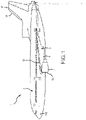
- the aircraft 1 may include multiple aircraft components 2 which may be susceptible to ice formation thereon.
- these aircraft components 2 may include a nacelle 4, a wing 6, a tail wing 8, or the like.
- a system 10 for inductive deicing or anti-icing features using CNT yarn may be located on areas of the aircraft components 2 that are most susceptible to ice formation (e.g., leading edges of the components 2).
- a system 10 may be located on a leading edge of the nacelle 4, a system 12 may be located on a leading edge of the wing 6, and a system 14 may be located on a leading edge of the tail wing 8.
- an exemplary system 100 for inductive heating of an aircraft surface (e.g., the nacelle 4, wing 6, tail wing 8, or the like) is shown.
- the system 100 may be used as any of the systems 10, 12, 14.
- the system 100 may be incorporated into, or installed onto, an aircraft component 102, such as at a leading edge 102 of the aircraft component 102.
- the aircraft component 102 may include an aircraft surface 104 which may include an outer portion 106.
- the system 100 may be installed on the outer portion 106 of the aircraft surface 104.
- the system 100 may include a conductive outer layer 108.
- the conductive outer layer 108 may be conductive and may further function as an erosion shield.
- the conductive outer layer 108 may include a metal (e.g., aluminum, titanium, stainless steel or the like), or a composite material (e.g., a thermoplastic, for example, Polyether Ether Ketone (PEEK), or thermoset such as epoxy, a carbon fabric or fibers or powders, or a CNT fabric or powders; e.g., the composite material may include PEEK or epoxy with CNT or another conductor integrated therein).
- the conductive outer layer 108 may further function as a lightning strike layer to reduce the likelihood or effect of a lightning strike.
- the conductive outer layer 108 may provide a conductive path to a ground so any lightning strike may follow the conductive path towards ground rather than flowing through and damaging non-conductive components.
- the system 100 may further include a CNT yarn 110.
- the CNT yarn 110 may be wound or otherwise formed into a CNT yarn coil 112.
- a CNT yarn coil may include any flat or three-dimensional coil that includes CNT yarn.
- a CNT yarn coil may include flat turns, a traditional coil shape, or the like.
- the CNT yarn 110 may be conductive.
- the CNT yarn coil 112 may include a first terminal 114 and a second terminal 116. Electrical current may flow from the first terminal 114 to the second terminal 116 (or vice versa) to generate an electric field from the CNT yarn coil 112, causing the CNT yarn coil 112 to operate as an inductor.
- the CNT yarn 110 may be coated and/or bonded with a dielectric polymer.
- the system 100 may also include an insulator 118.
- the insulator 118 may be located between the CNT yarn 110 and the conductive outer layer 108, electrically isolating the CNT yarn 110 from the conductive outer layer 108. In that regard and in response to current flowing through the CNT yarn coil 112, current may be applied to the conductive outer layer 108 via induction from the CNT yarn coil 112.
- the insulator 118 may be an adhesive capable of removably or permanently coupling the CNT yarn 110 to the conductive outer layer 108.
- the insulator 118 may include one or more of a thermoset (e.g., epoxy), thermoplastic (e.g., PEEK), glass fiber, fabric reinforced dielectric composite plies.
- two or more of the conductive outer layer 108, the insulator 118, and the CNT yarn 118 may be removably coupled together using a method other than an adhesive. This may provide additional ability to remove one or more of the components from the system 100 for replacement or repair.
- the CNT yarn 118 may be removably coupled to the aircraft surface 104 or may be permanently coupled to the aircraft surface 104.
- the coupling may be via epoxy, fasteners, or the like.
- another system 200 may have similar features as the system 100 of FIG. 1 .
- the system 200 may be included in, or added to, an aircraft component 201.
- the system 200 may include a CNT yarn 210 formed into a CNT yarn coil 212.
- the CNT yarn coil 212 may be similar to the CNT yarn coil 112 of FIG. 1 .
- the system 200 may further include an insulator 218.
- the insulator may include similar features as the insulator 118 of FIG. 1 .
- the system 200 may further include a conductive outer layer 208.
- the conductive outer layer 208 may include more than one plies.
- the conductive outer layer 208 may include a first ply 209 and a second ply 211.
- the first ply 209 and second ply 211 may be coupled together using any known technique.
- the plies 209, 211 may include the same or different material. Use of more than one plies 209, 211 may provide the benefit of improved erosion protection.
- an exemplary CNT yarn coil 402 is formed from a CNT yarn 400. As shown, the CNT yarn coil 402 may be a single, standalone coil.
- a system 400 may include multiple coils.
- the system 400 may include the first CNT yarn coil 402 and a second CNT yarn coil 406 located adjacent to the first CNT yarn coil 402.
- the coils 402, 406 may receive electrical power from a single power source or multiple power sources.
- the coils 402, 406 may be spaced apart to provide inductive heating to separate areas on an conductive outer layer.
- the coils 402, 406 may be interleaved in any pattern.
- the design 500 may include a first CNT yarn 502 that forms a first CNT yarn coil 504, and a second CNT yarn 506 that forms a second CNT yarn coil 508.
- the first coil 504 may be stacked on the second coil 508 (or vice versa).
- Current provided to the first coil 504 may be out-of-phase with the current provided to the second coil 508.
- This design may provide improved distribution of induction heating relative to single-phase designs.
- the first coil 504 and the second coil 508 may be interleaved with each other (and electrically isolated) to provide a two-phase design.
- any quantity of coils may be stacked or interleaved to provide any quantity of phases.
- the system 550 includes the two-phase CNT yarn coil design 500 and a second (potentially identical) two-phase CNT yarn coil design 552 located adjacent to the first two-phase CNT yarn coil design 500.
- This provides two-phase inductive heating over a greater surface area, thus heating a greater area of a conductive outer surface.
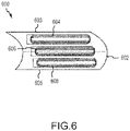
- a CNT yarn coil may be used to provide anti-ice features or deice features.
- an aircraft component 600 includes a leading edge 602, a first outer surface 603, and a second outer surface 605.
- a first CNT yarn coil 604 may be located proximate to the first outer surface 603 and may provide deicing capabilities.
- a third CNT yarn coil 608 may be located proximate to the second outer surface 605 and may also provide deicing capabilities.
- a second CNT yarn coil 606 may be located between the first outer surface 603 and the second outer surface 605 (and between the first CNT yarn coil 604 and the third CNT yarn coil 608) and may provide anti-icing capabilities.
- a method 700 for inductive heating of an aircraft surface is shown.
- a CNT yarn such as a CNT yarn coil
- An insulator may be positioned on the CNT yarn coil on a surface opposite the aircraft surface.
- a conductive outer layer may be positioned on the insulator. In that regard, the insulator may be located between the conductive outer layer and the CNT yarn coil.
- a second CNT yarn coil may be provided, e.g., on the aircraft surface or on the first CNT yarn coil.
- a second insulator or the first insulator may be positioned on the CNT yarn coil.
- the conductive outer layer may be in contact with the first or second insulator such that the insulator separates the conductive outer layer from the CNT yarn coil(s).
- electrical current may be provided to the CNT yarn coils.
- the electrical current may create an electric field around the CNT yarn coils, thus generating inductive heating on the conductive outer layer.
- references to "various embodiments”, “one embodiment”, “an embodiment”, “an example embodiment”, etc. indicate that the embodiment described may include a particular feature, structure, or characteristic, but every embodiment may not necessarily include the particular feature, structure, or characteristic. Moreover, such phrases are not necessarily referring to the same embodiment. Further, when a particular feature, structure, or characteristic is described in connection with an embodiment, it is submitted that it is within the knowledge of one skilled in the art to affect such feature, structure, or characteristic in connection with other embodiments whether or not explicitly described. After reading the description, it will be apparent to one skilled in the relevant art(s) how to implement the disclosure in alternative embodiments.
Landscapes
- Engineering & Computer Science (AREA)
- Chemical & Material Sciences (AREA)
- Physics & Mathematics (AREA)
- Nanotechnology (AREA)
- Organic Chemistry (AREA)
- Materials Engineering (AREA)
- Aviation & Aerospace Engineering (AREA)
- Electromagnetism (AREA)
- Inorganic Chemistry (AREA)
- Mechanical Engineering (AREA)
- Textile Engineering (AREA)
- Dispersion Chemistry (AREA)
- Spectroscopy & Molecular Physics (AREA)
- General Induction Heating (AREA)
Abstract
Description
- The present disclosure relates to systems and methods for heating aircraft components and surfaces using inductive heating.
- Various aircraft components (such as an airfoil, nacelle, wing, stabilizers, or the like) may be subjected to relatively cold temperatures (e.g., below freezing) as well as moisture. This combination may result in ice formation on the components. In that regard, it is desirable to reduce any ice that has formed and to reduce the likelihood of ice forming. Various types of heaters have been attempted to reduce or prevent such ice formation.
- Disclosed herein is a system for inductive heating of an aircraft surface. The system includes a conductive outer layer configured to be located on an outer portion of the aircraft surface. The system further includes a carbon nanotube (CNT) yarn or another type of carbon allotrope configured to receive and conduct electrical current. The system further includes an insulator located between the conductive outer layer and the CNT yarn such that the electrical current flowing through the CNT yarn generates induction heating on the conductive outer layer.
- In any of the foregoing embodiments, the CNT yarn is wound into a first CNT yarn coil and functions as an inductor.
- Any of the foregoing embodiments may further include a second CNT yarn coil located adjacent to the first CNT yarn coil such that the first CNT yarn coil generates induction heating on a first portion of the conductive outer layer and the second CNT yarn coil generates induction heating on a second portion of the conductive outer layer that is different than the first portion.
- Any of the foregoing embodiments may further include a second CNT yarn coil that at least partially overlaps the first CNT yarn coil such that a portion of the first CNT yarn coil and a portion of the second CNT yarn coil are aligned with a same portion of the conductive outer layer.
- Any of the foregoing embodiments may further include a second CNT yarn coil, wherein the first CNT yarn coil is configured to function as an anti-ice feature and the second CNT yarn coil is located closer to a first outer edge of the aircraft surface and configured to function as a deice feature.
- Any of the foregoing embodiments may further include a third CNT yarn coil located closer to a second outer edge of the aircraft surface and configured to function as a second de-ice feature, wherein the first CNT yarn coil is located between the second CNT yarn coil and the third CNT yarn coil.
- In any of the foregoing embodiments, the conductive outer layer includes a metal or other material and functions as an erosion shield.
- In any of the foregoing embodiments, the conductive outer layer includes a conductive composite material and functions as an erosion shield.
- In any of the foregoing embodiments, the conductive composite material includes at least one of a thermoplastic, a Polyether Ether Ketone (PEEK), a carbon fabric, a conductive filler or fabric, fibers, powder, or a CNT.
- In any of the foregoing embodiments, the conductive composite material includes at least one of a thermoset, an epoxy, a carbon fabric, or a CNT.
- In any of the foregoing embodiments, the insulator includes an adhesive configured to couple the conductive outer layer to the CNT yarn and to insulate the conductive outer layer from the CNT yarn.
- In any of the foregoing embodiments, the CNT yarn is removably coupled to the conductive outer layer to facilitate repair or replacement of at least one of the conductive outer layer or the CNT yarn.
- In any of the foregoing embodiments, the CNT yarn is bonded with a dielectric polymer.
- Also disclosed is an induction-heated aircraft component. The component includes an outer portion. The component further includes a conductive outer layer configured to be located on the outer portion. The component further includes a carbon nanotube (CNT) yarn configured to receive and conduct electrical current. The component further includes an insulator located between the conductive outer layer and the CNT yarn such that the electrical current flowing through the CNT yarn generates induction heating on the conductive outer layer.
- In any of the foregoing embodiments, the CNT yarn is wound into a first CNT yarn coil and functions as an inductor.
- In any of the foregoing embodiments, the insulator includes an adhesive configured to couple the conductive outer layer to the CNT yarn and to insulate the conductive outer layer from the CNT yarn.
- Also disclosed is a method for inductive heating of an aircraft surface. The method includes providing a carbon nanotube (CNT) yarn on the aircraft surface such that the CNT yarn is separated from a conductive outer layer by an insulator. The method further includes providing a first electrical current to the CNT yarn to generate induction heating on the conductive outer layer.
- In any of the foregoing embodiments, the CNT yarn is wound into a first CNT yarn coil and functions as an inductor.
- Any of the foregoing embodiments may further include providing a second CNT yarn coil separated from the conductive outer layer by the insulator or a second insulator; and providing a second electrical current to the second CNT yarn coil to generate additional inductive heating on the conductive outer layer.
- Any of the foregoing embodiments may further include coupling the CNT yarn to the conductive outer layer via the insulator such that the insulator functions as an adhesive.
- The foregoing features and elements may be combined in various combinations without exclusivity, unless expressly indicated otherwise. These features and elements as well as the operation thereof will become more apparent in light of the following description and the accompanying drawings. It should be understood, however, the following description and drawings are intended to be exemplary in nature and non-limiting.
- The subject matter of the present disclosure is particularly pointed out and distinctly claimed in the concluding portion of the specification. A more complete understanding of the present disclosure, however, may best be obtained by referring to the detailed description and claims when considered in connection with the figures, wherein like numerals denote like elements.
-
FIG. 1 illustrates an aircraft including various components, in accordance with various embodiments; -
FIG. 2 illustrates a system for providing inductive heating of an aircraft component, in accordance with various embodiments; -
FIG. 3 illustrates a system for providing inductive heating of an aircraft component, in accordance with various embodiments; -
FIG. 4A illustrates an exemplary carbon nanotube (CNT) yarn, in accordance with various embodiments; -
FIG. 4B illustrates multiple exemplary CNT yarns, in accordance with various embodiments; -
FIG. 5A illustrates a two-phase CNT yarn coil design, in accordance with various embodiments; -
FIG. 5B illustrates a system using multiple two-phase CNT yarn coil designs, in accordance with various embodiments; -
FIG. 6 illustrates an airfoil using CNT yarn coil designs to provide deicing and anti-icing functions, in accordance with various embodiments; and -
FIG. 7 is a flowchart illustrating a method for providing inductive heating of an aircraft component, in accordance with various embodiments. - The detailed description of exemplary embodiments herein makes reference to the accompanying drawings, which show exemplary embodiments by way of illustration. While these exemplary embodiments are described in sufficient detail to enable those skilled in the art to practice the exemplary embodiments of the disclosure, it should be understood that other embodiments may be realized and that logical changes and adaptations in design and construction may be made in accordance with this disclosure and the teachings herein. Thus, the detailed description herein is presented for purposes of illustration only and not limitation. The steps recited in any of the method or process descriptions may be executed in any order and are not necessarily limited to the order presented.
- Furthermore, any reference to singular includes plural embodiments, and any reference to more than one component or step may include a singular embodiment or step. Also, any reference to attached, fixed, connected or the like may include permanent, removable, temporary, partial, full and/or any other possible attachment option. Additionally, any reference to without contact (or similar phrases) may also include reduced contact or minimal contact. Surface shading lines may be used throughout the figures to denote different parts but not necessarily to denote the same or different materials.
- The present disclosure describes a system in which carbon nanotube (CNT) yarn is used as an induction conductor. CNT inherently resembles multi-strand litz wires which are suitable for being used at high frequencies without suffering from a skin effect. CNT yarn also has a higher maximum current density than copper wire, resulting in fewer turns than a copper coil, making CNT fabric yarn a more efficient and lower loss inductor than conventional inductors. Furthermore, CNT yarn materials also allow manufacturing of lightweight and strong electrical induction conductors. The density (for example, between 0.5 grams per milliliter (g/ml) and 2.5 g/ml, between 1 g/ml and 2 g/ml, or about 1.5 g/ml) of CNT fiber yarn is about one sixth the density of copper. CNT yarns are conformable and easier to be integrated in to composite ply for different shape of airfoils.
- Referring now to
FIG. 1 , an aircraft 1 is shown. The aircraft 1 may includemultiple aircraft components 2 which may be susceptible to ice formation thereon. For example, theseaircraft components 2 may include anacelle 4, awing 6, atail wing 8, or the like. Asystem 10 for inductive deicing or anti-icing features using CNT yarn may be located on areas of theaircraft components 2 that are most susceptible to ice formation (e.g., leading edges of the components 2). For example, asystem 10 may be located on a leading edge of thenacelle 4, asystem 12 may be located on a leading edge of thewing 6, and asystem 14 may be located on a leading edge of thetail wing 8. - Referring now to
FIG. 2 , anexemplary system 100 for inductive heating of an aircraft surface (e.g., thenacelle 4,wing 6,tail wing 8, or the like) is shown. Thesystem 100 may be used as any of thesystems system 100 may be incorporated into, or installed onto, anaircraft component 102, such as at aleading edge 102 of theaircraft component 102. Theaircraft component 102 may include anaircraft surface 104 which may include anouter portion 106. Thesystem 100 may be installed on theouter portion 106 of theaircraft surface 104. - The
system 100 may include a conductiveouter layer 108. The conductiveouter layer 108 may be conductive and may further function as an erosion shield. In that regard, the conductiveouter layer 108 may include a metal (e.g., aluminum, titanium, stainless steel or the like), or a composite material (e.g., a thermoplastic, for example, Polyether Ether Ketone (PEEK), or thermoset such as epoxy, a carbon fabric or fibers or powders, or a CNT fabric or powders; e.g., the composite material may include PEEK or epoxy with CNT or another conductor integrated therein). In various embodiments, the conductiveouter layer 108 may further function as a lightning strike layer to reduce the likelihood or effect of a lightning strike. In that regard, the conductiveouter layer 108 may provide a conductive path to a ground so any lightning strike may follow the conductive path towards ground rather than flowing through and damaging non-conductive components. - The
system 100 may further include aCNT yarn 110. In various embodiments, theCNT yarn 110 may be wound or otherwise formed into aCNT yarn coil 112. As used herein, a CNT yarn coil may include any flat or three-dimensional coil that includes CNT yarn. For example, a CNT yarn coil may include flat turns, a traditional coil shape, or the like. As referenced above, theCNT yarn 110 may be conductive. TheCNT yarn coil 112 may include afirst terminal 114 and asecond terminal 116. Electrical current may flow from thefirst terminal 114 to the second terminal 116 (or vice versa) to generate an electric field from theCNT yarn coil 112, causing theCNT yarn coil 112 to operate as an inductor. In various embodiments, theCNT yarn 110 may be coated and/or bonded with a dielectric polymer. - The
system 100 may also include aninsulator 118. Theinsulator 118 may be located between theCNT yarn 110 and the conductiveouter layer 108, electrically isolating theCNT yarn 110 from the conductiveouter layer 108. In that regard and in response to current flowing through theCNT yarn coil 112, current may be applied to the conductiveouter layer 108 via induction from theCNT yarn coil 112. In various embodiments, theinsulator 118 may be an adhesive capable of removably or permanently coupling theCNT yarn 110 to the conductiveouter layer 108. For example, theinsulator 118 may include one or more of a thermoset (e.g., epoxy), thermoplastic (e.g., PEEK), glass fiber, fabric reinforced dielectric composite plies. In various embodiments, two or more of the conductiveouter layer 108, theinsulator 118, and theCNT yarn 118 may be removably coupled together using a method other than an adhesive. This may provide additional ability to remove one or more of the components from thesystem 100 for replacement or repair. - In various embodiments, the
CNT yarn 118 may be removably coupled to theaircraft surface 104 or may be permanently coupled to theaircraft surface 104. For example, the coupling may be via epoxy, fasteners, or the like. - Referring now to
FIG. 3 , anothersystem 200 may have similar features as thesystem 100 ofFIG. 1 . In particular, thesystem 200 may be included in, or added to, anaircraft component 201. Thesystem 200 may include aCNT yarn 210 formed into aCNT yarn coil 212. TheCNT yarn coil 212 may be similar to theCNT yarn coil 112 ofFIG. 1 . Thesystem 200 may further include aninsulator 218. The insulator may include similar features as theinsulator 118 ofFIG. 1 . Thesystem 200 may further include a conductiveouter layer 208. However, the conductiveouter layer 208 may include more than one plies. For example, the conductiveouter layer 208 may include afirst ply 209 and asecond ply 211. Thefirst ply 209 andsecond ply 211 may be coupled together using any known technique. In addition, theplies - Referring now to
FIG. 4A , an exemplaryCNT yarn coil 402 is formed from aCNT yarn 400. As shown, theCNT yarn coil 402 may be a single, standalone coil. - Referring to
FIG. 4B , asystem 400 may include multiple coils. In particular, thesystem 400 may include the firstCNT yarn coil 402 and a secondCNT yarn coil 406 located adjacent to the firstCNT yarn coil 402. In that regard, thecoils coils coils - Turning to
FIG. 5A , a two-phase CNTyarn coil design 500 is shown. As shown, thedesign 500 may include afirst CNT yarn 502 that forms a firstCNT yarn coil 504, and asecond CNT yarn 506 that forms a secondCNT yarn coil 508. As shown, thefirst coil 504 may be stacked on the second coil 508 (or vice versa). Current provided to thefirst coil 504 may be out-of-phase with the current provided to thesecond coil 508. This design may provide improved distribution of induction heating relative to single-phase designs. In various embodiments, thefirst coil 504 and thesecond coil 508 may be interleaved with each other (and electrically isolated) to provide a two-phase design. In various embodiments, any quantity of coils may be stacked or interleaved to provide any quantity of phases. - Turning now to
FIG. 5B , a two-phase coil system 550 is shown. As shown, thesystem 550 includes the two-phase CNTyarn coil design 500 and a second (potentially identical) two-phase CNTyarn coil design 552 located adjacent to the first two-phase CNTyarn coil design 500. This provides two-phase inductive heating over a greater surface area, thus heating a greater area of a conductive outer surface. - Turning to
FIG. 6 , a CNT yarn coil may be used to provide anti-ice features or deice features. As shown, anaircraft component 600 includes aleading edge 602, a firstouter surface 603, and a secondouter surface 605. A firstCNT yarn coil 604 may be located proximate to the firstouter surface 603 and may provide deicing capabilities. A thirdCNT yarn coil 608 may be located proximate to the secondouter surface 605 and may also provide deicing capabilities. A secondCNT yarn coil 606 may be located between the firstouter surface 603 and the second outer surface 605 (and between the firstCNT yarn coil 604 and the third CNT yarn coil 608) and may provide anti-icing capabilities. - Referring now to
FIG. 7 , amethod 700 for inductive heating of an aircraft surface is shown. Inblock 702, a CNT yarn, such as a CNT yarn coil, is provided on an aircraft surface. An insulator may be positioned on the CNT yarn coil on a surface opposite the aircraft surface. A conductive outer layer may be positioned on the insulator. In that regard, the insulator may be located between the conductive outer layer and the CNT yarn coil. - In
block 704, a second CNT yarn coil may be provided, e.g., on the aircraft surface or on the first CNT yarn coil. A second insulator or the first insulator may be positioned on the CNT yarn coil. The conductive outer layer may be in contact with the first or second insulator such that the insulator separates the conductive outer layer from the CNT yarn coil(s). - In
block 706, electrical current may be provided to the CNT yarn coils. The electrical current may create an electric field around the CNT yarn coils, thus generating inductive heating on the conductive outer layer. - Benefits and other advantages have been described herein with regard to specific embodiments. Furthermore, the connecting lines shown in the various figures contained herein are intended to represent exemplary functional relationships and/or physical couplings between the various elements. It should be noted that many alternative or additional functional relationships or physical connections may be present in a practical system. However, the benefits, advantages, and any elements that may cause any benefit or advantage to occur or become more pronounced are not to be construed as critical, required, or essential features or elements of the disclosure. The scope of the invention is accordingly to be limited by nothing other than the appended claims, in which reference to an element in the singular is not intended to mean "one and only one" unless explicitly so stated, but rather "one or more." Moreover, where a phrase similar to "at least one of A, B, or C" is used in the claims, it is intended that the phrase be interpreted to mean that A alone may be present in an embodiment, B alone may be present in an embodiment, C alone may be present in an embodiment, or that any combination of the elements A, B and C may be present in a single embodiment; for example, A and B, A and C, B and C, or A and B and C.
- Systems, methods and apparatus are provided herein. In the detailed description herein, references to "various embodiments", "one embodiment", "an embodiment", "an example embodiment", etc., indicate that the embodiment described may include a particular feature, structure, or characteristic, but every embodiment may not necessarily include the particular feature, structure, or characteristic. Moreover, such phrases are not necessarily referring to the same embodiment. Further, when a particular feature, structure, or characteristic is described in connection with an embodiment, it is submitted that it is within the knowledge of one skilled in the art to affect such feature, structure, or characteristic in connection with other embodiments whether or not explicitly described. After reading the description, it will be apparent to one skilled in the relevant art(s) how to implement the disclosure in alternative embodiments.
Claims (15)
- A system for inductive heating of an aircraft surface, the system comprising:a conductive outer layer (108) configured to be located on an outer portion (106) of the aircraft surface (104);a carbon nanotube, CNT, yarn (110) configured to receive and conduct electrical current; andan insulator (118) located between the conductive outer layer and the CNT yarn such that the electrical current flowing through the CNT yarn generates induction heating on the conductive outer layer.
- The system of claim 1, wherein the CNT yarn is wound into a first CNT yarn coil (112) and functions as an inductor.
- The system of claim 2, further comprising a second CNT yarn coil located adjacent to the first CNT yarn coil such that the first CNT yarn coil generates induction heating on a first portion of the conductive outer layer and the second CNT yarn coil generates induction heating on a second portion of the conductive outer layer that is different than the first portion; or
further comprising a second CNT yarn coil (508) that at least partially overlaps the first CNT yarn coil such that a portion of the first CNT yarn coil and a portion of the second CNT yarn coil are aligned with a same portion of the conductive outer layer. - The system of claim 2, further comprising a second CNT yarn coil (606), wherein the first CNT yarn coil is configured to function as an anti-ice feature and the second CNT yarn coil is located closer to a first outer edge of the aircraft surface and configured to function as a deice feature.
- The system of claim 4, further comprising a third CNT yarn coil (608) located closer to a second outer edge of the aircraft surface and configured to function as a second de-ice feature, wherein the first CNT yarn coil is located between the second CNT yarn coil and the third CNT yarn coil.
- The system of any preceding claim, wherein the conductive outer layer includes a metal or other material and functions as an erosion shield, or wherein the conductive outer layer includes a conductive composite material and functions as an erosion shield.
- The system of claim 6, wherein the conductive composite material includes at least one of a thermoplastic, a Polyether ether ketone, PEEK, a carbon fabric, or a CNT, or wherein the conductive composite material includes at least one of a thermoset, an epoxy, a carbon fabric, or a CNT.
- The system of any preceding claim, wherein the insulator includes an adhesive configured to couple the conductive outer layer to the CNT yarn and to insulate the conductive outer layer from the CNT yarn.
- The system of any preceding claim, wherein the CNT yarn is removably coupled to the conductive outer layer to facilitate repair or replacement of at least one of the conductive outer layer or the CNT yarn.
- The system of any preceding claim, wherein the CNT yarn is bonded with a dielectric polymer.
- An induction-heated aircraft component, comprising:an outer portion (106); anda system (100) as claimed in any preceding claim for inductive heating of the aircraft component, the conductive outer layer configured to be located on the outer portion.
- A method for inductive heating of an aircraft surface, the method comprising:providing a carbon nanotube, CNT, yarn (110) on the aircraft surface (104) such that the CNT yarn is separated from a conductive outer layer by an insulator (118); andproviding a first electrical current to the CNT yarn to generate induction heating on the conductive outer layer.
- The method of claim 12, wherein the CNT yarn is wound into a first CNT yarn coil (112) and functions as an inductor.
- The method of claim 13, further comprising:providing a second CNT yarn coil (406) separated from the conductive outer layer by the insulator or a second insulator; andproviding a second electrical current to the second CNT yarn coil to generate additional inductive heating on the conductive outer layer.
- The method of claim 12, 13 or 14, further comprising coupling the CNT yarn to the conductive outer layer via the insulator such that the insulator functions as an adhesive.
Applications Claiming Priority (1)
| Application Number | Priority Date | Filing Date | Title |
|---|---|---|---|
| US17/138,453 US11952129B2 (en) | 2020-12-30 | 2020-12-30 | Carbon nanotube (CNT) or carbon allotrobe based induction heating for aircraft ice protection |
Publications (2)
| Publication Number | Publication Date |
|---|---|
| EP4025014A1 true EP4025014A1 (en) | 2022-07-06 |
| EP4025014B1 EP4025014B1 (en) | 2023-10-04 |
Family
ID=79025139
Family Applications (1)
| Application Number | Title | Priority Date | Filing Date |
|---|---|---|---|
| EP21218197.8A Active EP4025014B1 (en) | 2020-12-30 | 2021-12-29 | Carbon nanotube (cnt) or carbon allotrobe based induction heating for aircraft ice protection |
Country Status (2)
| Country | Link |
|---|---|
| US (1) | US11952129B2 (en) |
| EP (1) | EP4025014B1 (en) |
Families Citing this family (1)
| Publication number | Priority date | Publication date | Assignee | Title |
|---|---|---|---|---|
| CN120927736B (en) * | 2025-10-14 | 2025-12-05 | 中国科学技术大学 | Test apparatus and method for extreme surface loads of CO2 thermal protection components of aircraft |
Citations (3)
| Publication number | Priority date | Publication date | Assignee | Title |
|---|---|---|---|---|
| US10118705B2 (en) * | 2016-06-15 | 2018-11-06 | The Boeing Company | Hybrid acoustic and induction-heating systems and methods for impeding formation of ice |
| US10252806B2 (en) * | 2010-01-29 | 2019-04-09 | Gkn Aerospace Services Limited | Electrothermal heater mat |
| US20190176994A1 (en) * | 2017-10-30 | 2019-06-13 | Battelle Memorial Institute | Ice protection system and controller |
Family Cites Families (5)
| Publication number | Priority date | Publication date | Assignee | Title |
|---|---|---|---|---|
| JP2008032768A (en) | 2006-07-26 | 2008-02-14 | Matsushita Electric Ind Co Ltd | Lens actuator |
| FR2906786B1 (en) | 2006-10-09 | 2009-11-27 | Eurocopter France | METHOD AND DEVICE FOR DEFROSTING AN AIRCRAFT WALL |
| BRPI1014711A2 (en) | 2009-04-27 | 2016-04-12 | Applied Nanostrctured Solutions Llc | cnt-based resistance heating to defrost composite structures |
| EP2658777B1 (en) | 2010-12-31 | 2019-07-03 | Battelle Memorial Institute | Anti-icing, de-icing, and heating configuration, integration, and power methods for aircraft, aerodynamic and complex surfaces |
| DE102011119844A1 (en) | 2011-05-26 | 2012-12-13 | Eads Deutschland Gmbh | Composite structure with ice protection device and manufacturing process |
-
2020
- 2020-12-30 US US17/138,453 patent/US11952129B2/en active Active
-
2021
- 2021-12-29 EP EP21218197.8A patent/EP4025014B1/en active Active
Patent Citations (3)
| Publication number | Priority date | Publication date | Assignee | Title |
|---|---|---|---|---|
| US10252806B2 (en) * | 2010-01-29 | 2019-04-09 | Gkn Aerospace Services Limited | Electrothermal heater mat |
| US10118705B2 (en) * | 2016-06-15 | 2018-11-06 | The Boeing Company | Hybrid acoustic and induction-heating systems and methods for impeding formation of ice |
| US20190176994A1 (en) * | 2017-10-30 | 2019-06-13 | Battelle Memorial Institute | Ice protection system and controller |
Also Published As
| Publication number | Publication date |
|---|---|
| US20220204169A1 (en) | 2022-06-30 |
| US11952129B2 (en) | 2024-04-09 |
| EP4025014B1 (en) | 2023-10-04 |
Similar Documents
| Publication | Publication Date | Title |
|---|---|---|
| US10252806B2 (en) | Electrothermal heater mat | |
| US8981266B2 (en) | Electrical apparatus | |
| US8807483B2 (en) | Electrothermal heater mat | |
| US20120298803A1 (en) | Electrothermal heater | |
| US8993940B2 (en) | Dielectric component with electrical connection | |
| RU2466064C2 (en) | Method and device to prevent aircraft skin icing | |
| JP7640657B2 (en) | De-icing system | |
| US20090242703A1 (en) | Heating architecture for a composite fairing | |
| US9638044B2 (en) | Resistive-inductive propeller blade de-icing system including contactless power supply | |
| EP0983437A1 (en) | Device and method for heating and deicing wind energy turbine blades | |
| JPH09506462A (en) | Conductive composite heater device and manufacturing method thereof | |
| CN110195690B (en) | Blade ice melting device, blade and wind generating set | |
| EP4025014B1 (en) | Carbon nanotube (cnt) or carbon allotrobe based induction heating for aircraft ice protection | |
| CN101094986B (en) | Lightning conductor system for wind generator blades comprising carbon fibre laminates | |
| US20030000718A1 (en) | High-frequency de-icing of cableways | |
| US20120241434A1 (en) | Electrical power supply device for a resistor element, and an electrical system provided with said device and said resistor element | |
| CN109217218A (en) | For being vortexed the heat collecting apparatus of winterized equipment |
Legal Events
| Date | Code | Title | Description |
|---|---|---|---|
| PUAI | Public reference made under article 153(3) epc to a published international application that has entered the european phase |
Free format text: ORIGINAL CODE: 0009012 |
|
| STAA | Information on the status of an ep patent application or granted ep patent |
Free format text: STATUS: THE APPLICATION HAS BEEN PUBLISHED |
|
| AK | Designated contracting states |
Kind code of ref document: A1 Designated state(s): AL AT BE BG CH CY CZ DE DK EE ES FI FR GB GR HR HU IE IS IT LI LT LU LV MC MK MT NL NO PL PT RO RS SE SI SK SM TR |
|
| STAA | Information on the status of an ep patent application or granted ep patent |
Free format text: STATUS: REQUEST FOR EXAMINATION WAS MADE |
|
| 17P | Request for examination filed |
Effective date: 20221230 |
|
| RBV | Designated contracting states (corrected) |
Designated state(s): AL AT BE BG CH CY CZ DE DK EE ES FI FR GB GR HR HU IE IS IT LI LT LU LV MC MK MT NL NO PL PT RO RS SE SI SK SM TR |
|
| GRAP | Despatch of communication of intention to grant a patent |
Free format text: ORIGINAL CODE: EPIDOSNIGR1 |
|
| STAA | Information on the status of an ep patent application or granted ep patent |
Free format text: STATUS: GRANT OF PATENT IS INTENDED |
|
| INTG | Intention to grant announced |
Effective date: 20230508 |
|
| GRAS | Grant fee paid |
Free format text: ORIGINAL CODE: EPIDOSNIGR3 |
|
| GRAA | (expected) grant |
Free format text: ORIGINAL CODE: 0009210 |
|
| STAA | Information on the status of an ep patent application or granted ep patent |
Free format text: STATUS: THE PATENT HAS BEEN GRANTED |
|
| AK | Designated contracting states |
Kind code of ref document: B1 Designated state(s): AL AT BE BG CH CY CZ DE DK EE ES FI FR GB GR HR HU IE IS IT LI LT LU LV MC MK MT NL NO PL PT RO RS SE SI SK SM TR |
|
| REG | Reference to a national code |
Ref country code: GB Ref legal event code: FG4D |
|
| REG | Reference to a national code |
Ref country code: CH Ref legal event code: EP |
|
| REG | Reference to a national code |
Ref country code: DE Ref legal event code: R096 Ref document number: 602021005642 Country of ref document: DE |
|
| REG | Reference to a national code |
Ref country code: IE Ref legal event code: FG4D |
|
| P01 | Opt-out of the competence of the unified patent court (upc) registered |
Effective date: 20230922 |
|
| REG | Reference to a national code |
Ref country code: LT Ref legal event code: MG9D |
|
| REG | Reference to a national code |
Ref country code: NL Ref legal event code: MP Effective date: 20231004 |
|
| REG | Reference to a national code |
Ref country code: AT Ref legal event code: MK05 Ref document number: 1619210 Country of ref document: AT Kind code of ref document: T Effective date: 20231004 |
|
| PG25 | Lapsed in a contracting state [announced via postgrant information from national office to epo] |
Ref country code: NL Free format text: LAPSE BECAUSE OF FAILURE TO SUBMIT A TRANSLATION OF THE DESCRIPTION OR TO PAY THE FEE WITHIN THE PRESCRIBED TIME-LIMIT Effective date: 20231004 |
|
| PG25 | Lapsed in a contracting state [announced via postgrant information from national office to epo] |
Ref country code: GR Free format text: LAPSE BECAUSE OF FAILURE TO SUBMIT A TRANSLATION OF THE DESCRIPTION OR TO PAY THE FEE WITHIN THE PRESCRIBED TIME-LIMIT Effective date: 20240105 |
|
| PG25 | Lapsed in a contracting state [announced via postgrant information from national office to epo] |
Ref country code: IS Free format text: LAPSE BECAUSE OF FAILURE TO SUBMIT A TRANSLATION OF THE DESCRIPTION OR TO PAY THE FEE WITHIN THE PRESCRIBED TIME-LIMIT Effective date: 20240204 |
|
| PG25 | Lapsed in a contracting state [announced via postgrant information from national office to epo] |
Ref country code: LT Free format text: LAPSE BECAUSE OF FAILURE TO SUBMIT A TRANSLATION OF THE DESCRIPTION OR TO PAY THE FEE WITHIN THE PRESCRIBED TIME-LIMIT Effective date: 20231004 |
|
| PG25 | Lapsed in a contracting state [announced via postgrant information from national office to epo] |
Ref country code: AT Free format text: LAPSE BECAUSE OF FAILURE TO SUBMIT A TRANSLATION OF THE DESCRIPTION OR TO PAY THE FEE WITHIN THE PRESCRIBED TIME-LIMIT Effective date: 20231004 |
|
| PG25 | Lapsed in a contracting state [announced via postgrant information from national office to epo] |
Ref country code: ES Free format text: LAPSE BECAUSE OF FAILURE TO SUBMIT A TRANSLATION OF THE DESCRIPTION OR TO PAY THE FEE WITHIN THE PRESCRIBED TIME-LIMIT Effective date: 20231004 |
|
| PG25 | Lapsed in a contracting state [announced via postgrant information from national office to epo] |
Ref country code: LT Free format text: LAPSE BECAUSE OF FAILURE TO SUBMIT A TRANSLATION OF THE DESCRIPTION OR TO PAY THE FEE WITHIN THE PRESCRIBED TIME-LIMIT Effective date: 20231004 Ref country code: IS Free format text: LAPSE BECAUSE OF FAILURE TO SUBMIT A TRANSLATION OF THE DESCRIPTION OR TO PAY THE FEE WITHIN THE PRESCRIBED TIME-LIMIT Effective date: 20240204 Ref country code: GR Free format text: LAPSE BECAUSE OF FAILURE TO SUBMIT A TRANSLATION OF THE DESCRIPTION OR TO PAY THE FEE WITHIN THE PRESCRIBED TIME-LIMIT Effective date: 20240105 Ref country code: ES Free format text: LAPSE BECAUSE OF FAILURE TO SUBMIT A TRANSLATION OF THE DESCRIPTION OR TO PAY THE FEE WITHIN THE PRESCRIBED TIME-LIMIT Effective date: 20231004 Ref country code: BG Free format text: LAPSE BECAUSE OF FAILURE TO SUBMIT A TRANSLATION OF THE DESCRIPTION OR TO PAY THE FEE WITHIN THE PRESCRIBED TIME-LIMIT Effective date: 20240104 Ref country code: AT Free format text: LAPSE BECAUSE OF FAILURE TO SUBMIT A TRANSLATION OF THE DESCRIPTION OR TO PAY THE FEE WITHIN THE PRESCRIBED TIME-LIMIT Effective date: 20231004 Ref country code: PT Free format text: LAPSE BECAUSE OF FAILURE TO SUBMIT A TRANSLATION OF THE DESCRIPTION OR TO PAY THE FEE WITHIN THE PRESCRIBED TIME-LIMIT Effective date: 20240205 |
|
| PG25 | Lapsed in a contracting state [announced via postgrant information from national office to epo] |
Ref country code: SE Free format text: LAPSE BECAUSE OF FAILURE TO SUBMIT A TRANSLATION OF THE DESCRIPTION OR TO PAY THE FEE WITHIN THE PRESCRIBED TIME-LIMIT Effective date: 20231004 Ref country code: RS Free format text: LAPSE BECAUSE OF FAILURE TO SUBMIT A TRANSLATION OF THE DESCRIPTION OR TO PAY THE FEE WITHIN THE PRESCRIBED TIME-LIMIT Effective date: 20231004 Ref country code: PL Free format text: LAPSE BECAUSE OF FAILURE TO SUBMIT A TRANSLATION OF THE DESCRIPTION OR TO PAY THE FEE WITHIN THE PRESCRIBED TIME-LIMIT Effective date: 20231004 Ref country code: NO Free format text: LAPSE BECAUSE OF FAILURE TO SUBMIT A TRANSLATION OF THE DESCRIPTION OR TO PAY THE FEE WITHIN THE PRESCRIBED TIME-LIMIT Effective date: 20240104 Ref country code: LV Free format text: LAPSE BECAUSE OF FAILURE TO SUBMIT A TRANSLATION OF THE DESCRIPTION OR TO PAY THE FEE WITHIN THE PRESCRIBED TIME-LIMIT Effective date: 20231004 Ref country code: HR Free format text: LAPSE BECAUSE OF FAILURE TO SUBMIT A TRANSLATION OF THE DESCRIPTION OR TO PAY THE FEE WITHIN THE PRESCRIBED TIME-LIMIT Effective date: 20231004 |
|
| REG | Reference to a national code |
Ref country code: DE Ref legal event code: R097 Ref document number: 602021005642 Country of ref document: DE |
|
| PG25 | Lapsed in a contracting state [announced via postgrant information from national office to epo] |
Ref country code: DK Free format text: LAPSE BECAUSE OF FAILURE TO SUBMIT A TRANSLATION OF THE DESCRIPTION OR TO PAY THE FEE WITHIN THE PRESCRIBED TIME-LIMIT Effective date: 20231004 |
|
| PG25 | Lapsed in a contracting state [announced via postgrant information from national office to epo] |
Ref country code: CZ Free format text: LAPSE BECAUSE OF FAILURE TO SUBMIT A TRANSLATION OF THE DESCRIPTION OR TO PAY THE FEE WITHIN THE PRESCRIBED TIME-LIMIT Effective date: 20231004 |
|
| PG25 | Lapsed in a contracting state [announced via postgrant information from national office to epo] |
Ref country code: SK Free format text: LAPSE BECAUSE OF FAILURE TO SUBMIT A TRANSLATION OF THE DESCRIPTION OR TO PAY THE FEE WITHIN THE PRESCRIBED TIME-LIMIT Effective date: 20231004 |
|
| PG25 | Lapsed in a contracting state [announced via postgrant information from national office to epo] |
Ref country code: SM Free format text: LAPSE BECAUSE OF FAILURE TO SUBMIT A TRANSLATION OF THE DESCRIPTION OR TO PAY THE FEE WITHIN THE PRESCRIBED TIME-LIMIT Effective date: 20231004 Ref country code: SK Free format text: LAPSE BECAUSE OF FAILURE TO SUBMIT A TRANSLATION OF THE DESCRIPTION OR TO PAY THE FEE WITHIN THE PRESCRIBED TIME-LIMIT Effective date: 20231004 Ref country code: RO Free format text: LAPSE BECAUSE OF FAILURE TO SUBMIT A TRANSLATION OF THE DESCRIPTION OR TO PAY THE FEE WITHIN THE PRESCRIBED TIME-LIMIT Effective date: 20231004 Ref country code: IT Free format text: LAPSE BECAUSE OF FAILURE TO SUBMIT A TRANSLATION OF THE DESCRIPTION OR TO PAY THE FEE WITHIN THE PRESCRIBED TIME-LIMIT Effective date: 20231004 Ref country code: EE Free format text: LAPSE BECAUSE OF FAILURE TO SUBMIT A TRANSLATION OF THE DESCRIPTION OR TO PAY THE FEE WITHIN THE PRESCRIBED TIME-LIMIT Effective date: 20231004 Ref country code: DK Free format text: LAPSE BECAUSE OF FAILURE TO SUBMIT A TRANSLATION OF THE DESCRIPTION OR TO PAY THE FEE WITHIN THE PRESCRIBED TIME-LIMIT Effective date: 20231004 Ref country code: CZ Free format text: LAPSE BECAUSE OF FAILURE TO SUBMIT A TRANSLATION OF THE DESCRIPTION OR TO PAY THE FEE WITHIN THE PRESCRIBED TIME-LIMIT Effective date: 20231004 |
|
| PLBE | No opposition filed within time limit |
Free format text: ORIGINAL CODE: 0009261 |
|
| STAA | Information on the status of an ep patent application or granted ep patent |
Free format text: STATUS: NO OPPOSITION FILED WITHIN TIME LIMIT |
|
| PG25 | Lapsed in a contracting state [announced via postgrant information from national office to epo] |
Ref country code: LU Free format text: LAPSE BECAUSE OF NON-PAYMENT OF DUE FEES Effective date: 20231229 |
|
| PG25 | Lapsed in a contracting state [announced via postgrant information from national office to epo] |
Ref country code: MC Free format text: LAPSE BECAUSE OF FAILURE TO SUBMIT A TRANSLATION OF THE DESCRIPTION OR TO PAY THE FEE WITHIN THE PRESCRIBED TIME-LIMIT Effective date: 20231004 |
|
| REG | Reference to a national code |
Ref country code: BE Ref legal event code: MM Effective date: 20231231 |
|
| PG25 | Lapsed in a contracting state [announced via postgrant information from national office to epo] |
Ref country code: MC Free format text: LAPSE BECAUSE OF FAILURE TO SUBMIT A TRANSLATION OF THE DESCRIPTION OR TO PAY THE FEE WITHIN THE PRESCRIBED TIME-LIMIT Effective date: 20231004 Ref country code: LU Free format text: LAPSE BECAUSE OF NON-PAYMENT OF DUE FEES Effective date: 20231229 |
|
| 26N | No opposition filed |
Effective date: 20240705 |
|
| REG | Reference to a national code |
Ref country code: IE Ref legal event code: MM4A |
|
| PG25 | Lapsed in a contracting state [announced via postgrant information from national office to epo] |
Ref country code: IE Free format text: LAPSE BECAUSE OF NON-PAYMENT OF DUE FEES Effective date: 20231229 |
|
| PG25 | Lapsed in a contracting state [announced via postgrant information from national office to epo] |
Ref country code: BE Free format text: LAPSE BECAUSE OF NON-PAYMENT OF DUE FEES Effective date: 20231231 |
|
| PG25 | Lapsed in a contracting state [announced via postgrant information from national office to epo] |
Ref country code: SI Free format text: LAPSE BECAUSE OF FAILURE TO SUBMIT A TRANSLATION OF THE DESCRIPTION OR TO PAY THE FEE WITHIN THE PRESCRIBED TIME-LIMIT Effective date: 20231004 |
|
| PG25 | Lapsed in a contracting state [announced via postgrant information from national office to epo] |
Ref country code: SI Free format text: LAPSE BECAUSE OF FAILURE TO SUBMIT A TRANSLATION OF THE DESCRIPTION OR TO PAY THE FEE WITHIN THE PRESCRIBED TIME-LIMIT Effective date: 20231004 Ref country code: IE Free format text: LAPSE BECAUSE OF NON-PAYMENT OF DUE FEES Effective date: 20231229 Ref country code: BE Free format text: LAPSE BECAUSE OF NON-PAYMENT OF DUE FEES Effective date: 20231231 |
|
| PG25 | Lapsed in a contracting state [announced via postgrant information from national office to epo] |
Ref country code: FI Free format text: LAPSE BECAUSE OF FAILURE TO SUBMIT A TRANSLATION OF THE DESCRIPTION OR TO PAY THE FEE WITHIN THE PRESCRIBED TIME-LIMIT Effective date: 20231004 |
|
| PG25 | Lapsed in a contracting state [announced via postgrant information from national office to epo] |
Ref country code: CY Free format text: LAPSE BECAUSE OF FAILURE TO SUBMIT A TRANSLATION OF THE DESCRIPTION OR TO PAY THE FEE WITHIN THE PRESCRIBED TIME-LIMIT; INVALID AB INITIO Effective date: 20211229 |
|
| REG | Reference to a national code |
Ref country code: CH Ref legal event code: PL |
|
| PG25 | Lapsed in a contracting state [announced via postgrant information from national office to epo] |
Ref country code: CH Free format text: LAPSE BECAUSE OF NON-PAYMENT OF DUE FEES Effective date: 20241231 |
|
| PG25 | Lapsed in a contracting state [announced via postgrant information from national office to epo] |
Ref country code: TR Free format text: LAPSE BECAUSE OF FAILURE TO SUBMIT A TRANSLATION OF THE DESCRIPTION OR TO PAY THE FEE WITHIN THE PRESCRIBED TIME-LIMIT Effective date: 20231004 |
|
| PGFP | Annual fee paid to national office [announced via postgrant information from national office to epo] |
Ref country code: DE Payment date: 20251126 Year of fee payment: 5 |
|
| PGFP | Annual fee paid to national office [announced via postgrant information from national office to epo] |
Ref country code: GB Payment date: 20251119 Year of fee payment: 5 |
|
| PGFP | Annual fee paid to national office [announced via postgrant information from national office to epo] |
Ref country code: FR Payment date: 20251120 Year of fee payment: 5 |
|
| PG25 | Lapsed in a contracting state [announced via postgrant information from national office to epo] |
Ref country code: HU Free format text: LAPSE BECAUSE OF FAILURE TO SUBMIT A TRANSLATION OF THE DESCRIPTION OR TO PAY THE FEE WITHIN THE PRESCRIBED TIME-LIMIT; INVALID AB INITIO Effective date: 20211229 |