EP4024673A1 - Composites and methods of making composite materials - Google Patents
Composites and methods of making composite materials Download PDFInfo
- Publication number
- EP4024673A1 EP4024673A1 EP22150321.2A EP22150321A EP4024673A1 EP 4024673 A1 EP4024673 A1 EP 4024673A1 EP 22150321 A EP22150321 A EP 22150321A EP 4024673 A1 EP4024673 A1 EP 4024673A1
- Authority
- EP
- European Patent Office
- Prior art keywords
- wing
- wedge
- central portion
- wedges
- poles
- Prior art date
- Legal status (The legal status is an assumption and is not a legal conclusion. Google has not performed a legal analysis and makes no representation as to the accuracy of the status listed.)
- Granted
Links
Images

Classifications
-
- H—ELECTRICITY
- H02—GENERATION; CONVERSION OR DISTRIBUTION OF ELECTRIC POWER
- H02K—DYNAMO-ELECTRIC MACHINES
- H02K15/00—Processes or apparatus specially adapted for manufacturing, assembling, maintaining or repairing of dynamo-electric machines
- H02K15/13—Applying slot closure means in the cores; Manufacture of slot closure means
-
- H—ELECTRICITY
- H02—GENERATION; CONVERSION OR DISTRIBUTION OF ELECTRIC POWER
- H02K—DYNAMO-ELECTRIC MACHINES
- H02K3/00—Details of windings
- H02K3/04—Windings characterised by the conductor shape, form or construction, e.g. with bar conductors
- H02K3/24—Windings characterised by the conductor shape, form or construction, e.g. with bar conductors with channels or ducts for cooling medium between the conductors
-
- H—ELECTRICITY
- H02—GENERATION; CONVERSION OR DISTRIBUTION OF ELECTRIC POWER
- H02K—DYNAMO-ELECTRIC MACHINES
- H02K3/00—Details of windings
- H02K3/46—Fastening of windings on the stator or rotor structure
- H02K3/48—Fastening of windings on the stator or rotor structure in slots
- H02K3/487—Slot-closing devices
-
- H—ELECTRICITY
- H02—GENERATION; CONVERSION OR DISTRIBUTION OF ELECTRIC POWER
- H02K—DYNAMO-ELECTRIC MACHINES
- H02K3/00—Details of windings
- H02K3/46—Fastening of windings on the stator or rotor structure
- H02K3/52—Fastening salient pole windings or connections thereto
- H02K3/527—Fastening salient pole windings or connections thereto applicable to rotors only
-
- H—ELECTRICITY
- H02—GENERATION; CONVERSION OR DISTRIBUTION OF ELECTRIC POWER
- H02K—DYNAMO-ELECTRIC MACHINES
- H02K9/00—Arrangements for cooling or ventilating
- H02K9/22—Arrangements for cooling or ventilating by solid heat conducting material embedded in, or arranged in contact with, the stator or rotor, e.g. heat bridges
- H02K9/223—Heat bridges
-
- H—ELECTRICITY
- H02—GENERATION; CONVERSION OR DISTRIBUTION OF ELECTRIC POWER
- H02K—DYNAMO-ELECTRIC MACHINES
- H02K9/00—Arrangements for cooling or ventilating
- H02K9/22—Arrangements for cooling or ventilating by solid heat conducting material embedded in, or arranged in contact with, the stator or rotor, e.g. heat bridges
- H02K9/227—Heat sinks
-
- H—ELECTRICITY
- H02—GENERATION; CONVERSION OR DISTRIBUTION OF ELECTRIC POWER
- H02K—DYNAMO-ELECTRIC MACHINES
- H02K2205/00—Specific aspects not provided for in the other groups of this subclass relating to casings, enclosures, supports
- H02K2205/12—Machines characterised by means for reducing windage losses or windage noise
Definitions
- the present disclosure relates generally a wedge to be positioned between coils in an electrical generator, and more specifically to a wedge including a plurality of materials.
- Electrical generators typically include a shaft that is_driven for rotation, and which carries a plurality of field coils.
- the coils are typically separated by wedges.
- Wedges on electromagnetic machines are typically electrically conductive and thus have associated losses due to eddy currents. Wedges can be used smooth the area between laminations, thereby reducing friction and windage losses, however historically this has increased eddy current losses. Thus one loss cannot be reduced without increasing the other.
- wedges have been generally been considered satisfactory for their intended purpose. However, there is still a need in the art for improved wedges having improved thermal conductivity while minimizing other losses. The present disclosure provides a solution for this need.
- a rotor for a generator includes a shaft, a rotor core radially outward from the shaft and having a plurality of poles spanning axially along the rotor core, a plurality of windings wrapped axially around each of the plurality of poles, a plurality of wedges, each wedge being positioned between two adjacent poles of the plurality of poles, each wedge having a central portion comprising at least a first material, a first wing integrally attached to the central portion, and a second wing integrally attached to the central portion opposite the first wing, wherein the first wing, and the second wing include a second material.
- the central portion can include the second material.
- the first material can be electrically non-conductive.
- the second material can be electrically conductive.
- the first material can include titanium.
- the second material can include aluminum.
- the central portion is primarily composed of the second material.
- the central portion can include a quadrilateral section radially outward from a triangular central leg separating the first wing from the second wing.
- the quadrilateral section can include the first material and the second material.
- the quadrilateral section can include three outward facing edges, wherein each of the edges includes the second material, and two of the edges do not include the first material.
- the quadrilateral section can includes a first "L" shaped portion including the second material.
- the quadrilateral section includes a second "L" shaped portion can include the second material bracketing a portion of the first material with the first "L" shaped portion.
- first wing and the second wing include the first material, a portion of an outer edge of the first wing, and a portion of an outer edge of the second wing include the first material.
- the central portion can include an aperture configured to allow coolant oil flow.
- the central portion can include a fastener located radially inward of the aperture.
- the fastener can include steel.
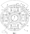
- FIG. 1 a partial view of an exemplary embodiment of a rotor accordance with the disclosure is shown in FIG. 1 and is designated generally by reference character 100.
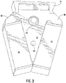
- FIGs. 2 and 3 Other embodiments of the rotor and wedges used therein in accordance with the disclosure, or aspects thereof, are provided in FIGs. 2 and 3 , as will be described.
- the disclosure describes a wedge that is both smooth on the outer diameter to reduce friction and windage, and yet limits high conductivity, both electrical and thermal, to regions where heat needs to be transferred.
- FIG. 1 shows a cross-section of a machine 20 having a central shaft 26, which is driven to rotate by a source of rotation, such as a gas turbine engine 27 (shown schematically) and adjacent to a stator 22 (shown schematically) to generate electricity.
- the rotor 24 includes a lamination stack 28 having poles 35 with circumferentially extending wedges 32.
- the wedges 32 sit in a channel radially inwardly of circumferentially opposed pole tips 34 on poles 35.
- the channels receive field coils or windings 30 and 31, which are wound around the poles 35.
- the wedge 32 separates and supports adjacent coils 30 and 31.
- Fig. 2 shows a detailed view of a wedge 32 of Fig. 1 .
- the wedge 32 includes a central portion 40.
- the central portion 40 includes a first material and a second material.
- a first wing 46 is integrally attached to the central portion 40, and a second wing 48 is integrally attached to the central portion 40 opposite the first wing 46.
- the first wing 46 and the second wing 48 include the second material only.
- Each of the windings, seen in Fig. 1 contact the wings 46, 48 of each of the wedges and do not contact the first material section of each of the wedges.
- the first material can be electrically non-conductive, such as titanium.
- the second material can be electrically conductive, such as aluminum.
- the central portion 40 is primarily composed of the second material, with only a small portion touching the outer surface, with the outer surface having an air gap placed after it.
- the central portion 40 includes a quadrilateral section 50 positioned radially outward from a triangular central leg 52 which separates the first wing 46 from the second wing 48.
- the quadrilateral section 50 includes the small section 54 of the first material.
- the quadrilateral section 50 can include three outward facing edges 56, 58, 60, where each of the edges are partially made up of the second material, and two of the edges 56 and 60 do not include the first material.
- the quadrilateral section 50 includes a first "L" shaped portion 62 made of the second material and a second "L" shaped portion 64 bracketing the first material section 54.
- the central portion 40 also includes an oil flow aperture 68 and a fastener aperture 66 located radially inward of the aperture.
- the fastener can include steel, and more specifically cobalt steel.
- Fig. 3 shows an embodiment of the wedge 32 wherein the first material section 54 hugs the second material section such that each of the wings 46 and 48 include the first material.
Landscapes
- Engineering & Computer Science (AREA)
- Power Engineering (AREA)
- Manufacturing & Machinery (AREA)
- Insulation, Fastening Of Motor, Generator Windings (AREA)
Abstract
Description
- The present disclosure relates generally a wedge to be positioned between coils in an electrical generator, and more specifically to a wedge including a plurality of materials.
- Electrical generators typically include a shaft that is_driven for rotation, and which carries a plurality of field coils. The coils are typically separated by wedges. Wedges on electromagnetic machines are typically electrically conductive and thus have associated losses due to eddy currents. Wedges can be used smooth the area between laminations, thereby reducing friction and windage losses, however historically this has increased eddy current losses. Thus one loss cannot be reduced without increasing the other. Historically wedges have been generally been considered satisfactory for their intended purpose. However, there is still a need in the art for improved wedges having improved thermal conductivity while minimizing other losses. The present disclosure provides a solution for this need.
- A rotor for a generator includes a shaft, a rotor core radially outward from the shaft and having a plurality of poles spanning axially along the rotor core, a plurality of windings wrapped axially around each of the plurality of poles, a plurality of wedges, each wedge being positioned between two adjacent poles of the plurality of poles, each wedge having a central portion comprising at least a first material, a first wing integrally attached to the central portion, and a second wing integrally attached to the central portion opposite the first wing, wherein the first wing, and the second wing include a second material.
- Each of the windings can contact the second material of each of the wedges and not contact the first material of each of the wedges. The central portion can include the second material. The first material can be electrically non-conductive. The second material can be electrically conductive. The first material can include titanium. The second material can include aluminum. The central portion is primarily composed of the second material.
- The central portion can include a quadrilateral section radially outward from a triangular central leg separating the first wing from the second wing. The quadrilateral section can include the first material and the second material. The quadrilateral section can include three outward facing edges, wherein each of the edges includes the second material, and two of the edges do not include the first material. The quadrilateral section can includes a first "L" shaped portion including the second material. The quadrilateral section includes a second "L" shaped portion can include the second material bracketing a portion of the first material with the first "L" shaped portion. It is also considered that the first wing and the second wing include the first material, a portion of an outer edge of the first wing, and a portion of an outer edge of the second wing include the first material. The central portion can include an aperture configured to allow coolant oil flow. The central portion can include a fastener located radially inward of the aperture. The fastener can include steel.
- These and other features of the systems and methods of the subject disclosure will become more readily apparent to those skilled in the art from the following detailed description of the preferred embodiments taken in conjunction with the drawings..
- So that those skilled in the art to which the subject disclosure appertains will readily understand how to make and use the devices and methods of the subject disclosure without undue experimentation, embodiments thereof will be described in detail herein below with reference to certain figures, wherein:
-
FIG. 1 is a schematic sectional view of a machine; -
FIG. 2 is a perspective view of a wedge for the machine ofFig. 2 ; and -
FIG. 3 is a perspective view of an embodiment of a wedge for the machine ofFig. 1 . - Reference will now be made to the drawings wherein like reference numerals identify similar structural features or aspects of the subject disclosure. For purposes of explanation and illustration, and not limitation, a partial view of an exemplary embodiment of a rotor accordance with the disclosure is shown in
FIG. 1 and is designated generally by reference character 100. Other embodiments of the rotor and wedges used therein in accordance with the disclosure, or aspects thereof, are provided inFIGs. 2 and3 , as will be described. The disclosure describes a wedge that is both smooth on the outer diameter to reduce friction and windage, and yet limits high conductivity, both electrical and thermal, to regions where heat needs to be transferred. -
FIG. 1 shows a cross-section of amachine 20 having acentral shaft 26, which is driven to rotate by a source of rotation, such as a gas turbine engine 27 (shown schematically) and adjacent to a stator 22 (shown schematically) to generate electricity. Therotor 24 includes alamination stack 28 havingpoles 35 with circumferentially extendingwedges 32. Thewedges 32 sit in a channel radially inwardly of circumferentially opposedpole tips 34 onpoles 35. The channels receive field coils orwindings poles 35. Thewedge 32 separates and supportsadjacent coils -
Fig. 2 shows a detailed view of awedge 32 ofFig. 1 . Thewedge 32 includes acentral portion 40. Thecentral portion 40 includes a first material and a second material. Afirst wing 46 is integrally attached to thecentral portion 40, and asecond wing 48 is integrally attached to thecentral portion 40 opposite thefirst wing 46. Thefirst wing 46 and thesecond wing 48 include the second material only. Each of the windings, seen inFig. 1 , contact thewings - The first material can be electrically non-conductive, such as titanium. The second material can be electrically conductive, such as aluminum. The
central portion 40 is primarily composed of the second material, with only a small portion touching the outer surface, with the outer surface having an air gap placed after it. Thecentral portion 40 includes aquadrilateral section 50 positioned radially outward from a triangularcentral leg 52 which separates thefirst wing 46 from thesecond wing 48. Thequadrilateral section 50 includes thesmall section 54 of the first material. Thequadrilateral section 50 can include three outwardfacing edges edges quadrilateral section 50 includes a first "L"shaped portion 62 made of the second material and a second "L"shaped portion 64 bracketing thefirst material section 54. Thecentral portion 40 also includes anoil flow aperture 68 and afastener aperture 66 located radially inward of the aperture. The fastener can include steel, and more specifically cobalt steel.Fig. 3 shows an embodiment of thewedge 32 wherein thefirst material section 54 hugs the second material section such that each of thewings - The methods and systems of the present disclosure, as described above and shown in the drawings, provide for wedges with better conductivity properties. While the apparatus and methods of the subject disclosure have been shown and described with reference to preferred embodiments, those skilled in the art will readily appreciate that changes and/or modifications may be made thereto without departing from the scope of the subject disclosure.
Claims (15)
- A wedge (32) for use in an electric machine comprising:a central portion (40) comprising at least a first material;a first wing (46) integrally attached to the central portion (40); anda second wing (48) integrally attached to the central portion (40) opposite the first wing (46), wherein the first wing (46), and the second wing (48) include a second material.
- The wedge (32) of claim 1, wherein the central portion (40) includes the second material.
- The wedge (32) of claim 1 or 2, wherein the first material is not electrically conductive.
- The wedge (32) of any preceding claim, wherein the second material is electrically conductive.
- The wedge (32) of any preceding claim, wherein the first material includes titanium.
- The wedge (32) of any preceding claim, wherein the second material includes aluminum.
- The wedge (32) of any preceding claim, wherein the central portion (40) is primarily composed of the second material.
- The wedge (32) of any preceding claim, wherein the central portion (40) includes a quadrilateral section radially outward from a triangular central leg separating the first wing (46) from the second wing (48).
- The wedge (32) of claim 8, wherein the quadrilateral section includes the first material and the second material, and optionally wherein the quadrilateral section includes three outward facing edges, wherein each of the edges includes the second material, and two of the edges do not include the first material.
- The wedge (32) of any preceding claim, wherein the quadrilateral section includes a first "L" shaped portion (64) including the second material, and optionally wherein the quadrilateral section includes a second "L" shaped portion (64) including the second material bracketing a portion of the first material with the first "L" shaped portion (64).
- The wedge (32) of any preceding claim, wherein the central portion (40) includes an aperture configured to allow coolant oil flow.
- The wedge (32) of claim 11, wherein the central portion (40) includes a fastener or fastener aperture located radially inward of the aperture, and optionally wherein the fastener includes steel.
- The wedge (32) of any preceding claim, wherein the first wing (46) and the second wing (48) include the first material, and optionally wherein a portion of an outer edge of the first wing (46), and a portion of an outer edge of the second wing (48) include the first material.
- A rotor for a generator comprising:a shaft;a rotor core radially outward from the shaft and having a plurality of poles spanning axially along the rotor core;a plurality of windings wrapped axially around each of the plurality of poles; anda plurality of wedges (32), each wedge (32) being positioned between two adjacent poles of the plurality of poles, each wedge (32) having a central portion (40) comprising at least a first material;a first wing (46) integrally attached to the central portion (40); anda second wing (48) integrally attached to the central portion (40) opposite the first wing (46), wherein the first wing (46), and the second wing (48) include a second material.
- The rotor of claim 14 wherein each of the windings contacts the second material of each of the wedges (32), or wherein each of the windings does not contact the first material of each of the wedges (32).
Applications Claiming Priority (1)
| Application Number | Priority Date | Filing Date | Title |
|---|---|---|---|
| US17/142,189 US11539273B2 (en) | 2021-01-05 | 2021-01-05 | Composites and methods of making composite materials |
Publications (2)
| Publication Number | Publication Date |
|---|---|
| EP4024673A1 true EP4024673A1 (en) | 2022-07-06 |
| EP4024673B1 EP4024673B1 (en) | 2026-02-25 |
Family
ID=79230968
Family Applications (1)
| Application Number | Title | Priority Date | Filing Date |
|---|---|---|---|
| EP22150321.2A Active EP4024673B1 (en) | 2021-01-05 | 2022-01-05 | Wedge for rotor field coils and rotor comprising the same |
Country Status (2)
| Country | Link |
|---|---|
| US (2) | US11539273B2 (en) |
| EP (1) | EP4024673B1 (en) |
Families Citing this family (2)
| Publication number | Priority date | Publication date | Assignee | Title |
|---|---|---|---|---|
| DE102023101007A1 (en) * | 2023-01-17 | 2024-07-18 | Bayerische Motoren Werke Aktiengesellschaft | Electric machine |
| CN117543901A (en) * | 2023-11-21 | 2024-02-09 | 西比里电机技术(苏州)有限公司 | Totally-enclosed external rotor motor |
Citations (4)
| Publication number | Priority date | Publication date | Assignee | Title |
|---|---|---|---|---|
| US20040263019A1 (en) * | 2003-06-24 | 2004-12-30 | Buchan Neil Fergus | Rotor assembly for dynamo electric machines |
| US7821171B2 (en) * | 2008-12-02 | 2010-10-26 | Hamilton Sundstrand Corporation | Generator wedge with reduced eddy current losses |
| US20180278112A1 (en) * | 2017-03-27 | 2018-09-27 | Hamilton Sundstrand Corporation | Wedges with q-axis damper circuits |
| WO2019180308A1 (en) * | 2018-03-20 | 2019-09-26 | Lappeenrannan-Lahden Teknillinen Yliopisto Lut | A stator of an electric machine and an electric machine |
Family Cites Families (6)
| Publication number | Priority date | Publication date | Assignee | Title |
|---|---|---|---|---|
| DE1513793C3 (en) | 1966-02-28 | 1973-09-20 | Licentia Patent-Verwaltungs-Gmbh, 6000 Frankfurt | Slot wedge made of sheet metal lamellas and pressed together with a tension bolt for an electrical machine |
| CA2175510C (en) * | 1995-05-02 | 2005-02-01 | Masao Iwata | Magneto electric generator rotor and an implement for removing this rotor |
| US6124659A (en) | 1999-08-20 | 2000-09-26 | Siemens Westinghouse Power Corporation | Stator wedge having abrasion-resistant edge and methods of forming same |
| US6984910B2 (en) * | 2003-01-13 | 2006-01-10 | Honeywell International, Inc. | Generator with composite rotor coil retention components |
| JP2015027161A (en) * | 2013-07-25 | 2015-02-05 | 株式会社東芝 | Rotating electric machine |
| US10720809B2 (en) | 2017-11-20 | 2020-07-21 | Hamilton Sundstrand Corporation | Rotor wedges with eddy current inhibitors |
-
2021
- 2021-01-05 US US17/142,189 patent/US11539273B2/en active Active
-
2022
- 2022-01-05 EP EP22150321.2A patent/EP4024673B1/en active Active
- 2022-12-27 US US18/089,562 patent/US11955849B2/en active Active
Patent Citations (4)
| Publication number | Priority date | Publication date | Assignee | Title |
|---|---|---|---|---|
| US20040263019A1 (en) * | 2003-06-24 | 2004-12-30 | Buchan Neil Fergus | Rotor assembly for dynamo electric machines |
| US7821171B2 (en) * | 2008-12-02 | 2010-10-26 | Hamilton Sundstrand Corporation | Generator wedge with reduced eddy current losses |
| US20180278112A1 (en) * | 2017-03-27 | 2018-09-27 | Hamilton Sundstrand Corporation | Wedges with q-axis damper circuits |
| WO2019180308A1 (en) * | 2018-03-20 | 2019-09-26 | Lappeenrannan-Lahden Teknillinen Yliopisto Lut | A stator of an electric machine and an electric machine |
Also Published As
| Publication number | Publication date |
|---|---|
| US11539273B2 (en) | 2022-12-27 |
| US11955849B2 (en) | 2024-04-09 |
| US20220216773A1 (en) | 2022-07-07 |
| US20230170770A1 (en) | 2023-06-01 |
| EP4024673B1 (en) | 2026-02-25 |
Similar Documents
| Publication | Publication Date | Title |
|---|---|---|
| US4556809A (en) | Combination synchronous and asynchronous electric motor | |
| US9287742B2 (en) | Spoke permanent magnet machine with reduced torque ripple and method of manufacturing thereof | |
| US10523079B2 (en) | Rotor assembly for an electric machine with thermal management features | |
| US7436096B2 (en) | Rotor having permanent magnets and axialy-extending channels | |
| US9590457B2 (en) | Stator of a rotary electric machine | |
| US10749385B2 (en) | Dual magnetic phase material rings for AC electric machines | |
| US11955849B2 (en) | Composites and methods of making composite materials | |
| CN105048663A (en) | Apparatus for a high speed sleeveless rotor | |
| JP2011036010A (en) | Rotating electrical machine | |
| US20140327330A1 (en) | Dynamoelectric machine having enhanced rotor ventilation | |
| US12126224B2 (en) | Method and apparatus for cooling a rotor assembly | |
| US20170141626A1 (en) | Dual-stator electrical generation apparatus | |
| US4281266A (en) | Dynamoelectric machine with flux screen | |
| US12088159B2 (en) | Generator with lap windings and segmented permanent magnets | |
| US20180205275A1 (en) | Surface mount permanent magnet attachment for electric machine | |
| CN108288879B (en) | Stator support for an electric machine | |
| US20150372575A1 (en) | High speed induction machine with fractional-slot tooth-coil winding | |
| CN112655136B (en) | Enhanced geometry of permanent magnet claw-shaped pole segments | |
| US11031832B2 (en) | Stator of rotating electrical machine and method of manufacturing stator of rotating electrical machine | |
| US7508107B2 (en) | High current rotating exciter | |
| CN214756014U (en) | Electric machine | |
| JP2018038102A (en) | Rotary electric machine | |
| JPH1023692A (en) | Rotating electric machine rotor | |
| JP2021522767A (en) | Rotor for rotating electromechanical | |
| CN115378212A (en) | Electric machine with rotor shaft and lamination stack |
Legal Events
| Date | Code | Title | Description |
|---|---|---|---|
| PUAI | Public reference made under article 153(3) epc to a published international application that has entered the european phase |
Free format text: ORIGINAL CODE: 0009012 |
|
| STAA | Information on the status of an ep patent application or granted ep patent |
Free format text: STATUS: THE APPLICATION HAS BEEN PUBLISHED |
|
| AK | Designated contracting states |
Kind code of ref document: A1 Designated state(s): AL AT BE BG CH CY CZ DE DK EE ES FI FR GB GR HR HU IE IS IT LI LT LU LV MC MK MT NL NO PL PT RO RS SE SI SK SM TR |
|
| STAA | Information on the status of an ep patent application or granted ep patent |
Free format text: STATUS: REQUEST FOR EXAMINATION WAS MADE |
|
| 17P | Request for examination filed |
Effective date: 20230105 |
|
| RBV | Designated contracting states (corrected) |
Designated state(s): AL AT BE BG CH CY CZ DE DK EE ES FI FR GB GR HR HU IE IS IT LI LT LU LV MC MK MT NL NO PL PT RO RS SE SI SK SM TR |
|
| GRAP | Despatch of communication of intention to grant a patent |
Free format text: ORIGINAL CODE: EPIDOSNIGR1 |
|
| STAA | Information on the status of an ep patent application or granted ep patent |
Free format text: STATUS: GRANT OF PATENT IS INTENDED |
|
| INTG | Intention to grant announced |
Effective date: 20250401 |
|
| GRAJ | Information related to disapproval of communication of intention to grant by the applicant or resumption of examination proceedings by the epo deleted |
Free format text: ORIGINAL CODE: EPIDOSDIGR1 |
|
| STAA | Information on the status of an ep patent application or granted ep patent |
Free format text: STATUS: REQUEST FOR EXAMINATION WAS MADE |
|
| GRAP | Despatch of communication of intention to grant a patent |
Free format text: ORIGINAL CODE: EPIDOSNIGR1 |
|
| STAA | Information on the status of an ep patent application or granted ep patent |
Free format text: STATUS: GRANT OF PATENT IS INTENDED |
|
| INTC | Intention to grant announced (deleted) | ||
| INTG | Intention to grant announced |
Effective date: 20250910 |
|
| GRAS | Grant fee paid |
Free format text: ORIGINAL CODE: EPIDOSNIGR3 |
|
| GRAA | (expected) grant |
Free format text: ORIGINAL CODE: 0009210 |
|
| STAA | Information on the status of an ep patent application or granted ep patent |
Free format text: STATUS: THE PATENT HAS BEEN GRANTED |
|
| AK | Designated contracting states |
Kind code of ref document: B1 Designated state(s): AL AT BE BG CH CY CZ DE DK EE ES FI FR GB GR HR HU IE IS IT LI LT LU LV MC MK MT NL NO PL PT RO RS SE SI SK SM TR |
|
| REG | Reference to a national code |
Ref country code: CH Ref legal event code: F10 Free format text: ST27 STATUS EVENT CODE: U-0-0-F10-F00 (AS PROVIDED BY THE NATIONAL OFFICE) Effective date: 20260225 Ref country code: GB Ref legal event code: FG4D |
|
| REG | Reference to a national code |
Ref country code: DE Ref legal event code: R096 Ref document number: 602022030906 Country of ref document: DE |
|
| REG | Reference to a national code |
Ref country code: IE Ref legal event code: FG4D |
|
| REG | Reference to a national code |
Ref country code: NL Ref legal event code: MP Effective date: 20260225 |
|
| PG25 | Lapsed in a contracting state [announced via postgrant information from national office to epo] |
Ref country code: RS Free format text: LAPSE BECAUSE OF FAILURE TO SUBMIT A TRANSLATION OF THE DESCRIPTION OR TO PAY THE FEE WITHIN THE PRESCRIBED TIME-LIMIT Effective date: 20260525 |
|
| PG25 | Lapsed in a contracting state [announced via postgrant information from national office to epo] |
Ref country code: ES Free format text: LAPSE BECAUSE OF FAILURE TO SUBMIT A TRANSLATION OF THE DESCRIPTION OR TO PAY THE FEE WITHIN THE PRESCRIBED TIME-LIMIT Effective date: 20260225 |
|
| PG25 | Lapsed in a contracting state [announced via postgrant information from national office to epo] |
Ref country code: PL Free format text: LAPSE BECAUSE OF FAILURE TO SUBMIT A TRANSLATION OF THE DESCRIPTION OR TO PAY THE FEE WITHIN THE PRESCRIBED TIME-LIMIT Effective date: 20260225 |
|
| PG25 | Lapsed in a contracting state [announced via postgrant information from national office to epo] |
Ref country code: GR Free format text: LAPSE BECAUSE OF FAILURE TO SUBMIT A TRANSLATION OF THE DESCRIPTION OR TO PAY THE FEE WITHIN THE PRESCRIBED TIME-LIMIT Effective date: 20260526 |
|
| REG | Reference to a national code |
Ref country code: LT Ref legal event code: MG9D |
|
| PG25 | Lapsed in a contracting state [announced via postgrant information from national office to epo] |
Ref country code: LT Free format text: LAPSE BECAUSE OF FAILURE TO SUBMIT A TRANSLATION OF THE DESCRIPTION OR TO PAY THE FEE WITHIN THE PRESCRIBED TIME-LIMIT Effective date: 20260225 |
|
| PG25 | Lapsed in a contracting state [announced via postgrant information from national office to epo] |
Ref country code: NO Free format text: LAPSE BECAUSE OF FAILURE TO SUBMIT A TRANSLATION OF THE DESCRIPTION OR TO PAY THE FEE WITHIN THE PRESCRIBED TIME-LIMIT Effective date: 20260525 |
|
| PG25 | Lapsed in a contracting state [announced via postgrant information from national office to epo] |
Ref country code: SE Free format text: LAPSE BECAUSE OF FAILURE TO SUBMIT A TRANSLATION OF THE DESCRIPTION OR TO PAY THE FEE WITHIN THE PRESCRIBED TIME-LIMIT Effective date: 20260225 Ref country code: FI Free format text: LAPSE BECAUSE OF FAILURE TO SUBMIT A TRANSLATION OF THE DESCRIPTION OR TO PAY THE FEE WITHIN THE PRESCRIBED TIME-LIMIT Effective date: 20260225 Ref country code: AT Free format text: LAPSE BECAUSE OF FAILURE TO SUBMIT A TRANSLATION OF THE DESCRIPTION OR TO PAY THE FEE WITHIN THE PRESCRIBED TIME-LIMIT Effective date: 20260225 |
|
| REG | Reference to a national code |
Ref country code: AT Ref legal event code: MK05 Ref document number: 1892125 Country of ref document: AT Kind code of ref document: T Effective date: 20260225 |
|
| PG25 | Lapsed in a contracting state [announced via postgrant information from national office to epo] |
Ref country code: HR Free format text: LAPSE BECAUSE OF FAILURE TO SUBMIT A TRANSLATION OF THE DESCRIPTION OR TO PAY THE FEE WITHIN THE PRESCRIBED TIME-LIMIT Effective date: 20260225 |
|
| PG25 | Lapsed in a contracting state [announced via postgrant information from national office to epo] |
Ref country code: PT Free format text: LAPSE BECAUSE OF FAILURE TO SUBMIT A TRANSLATION OF THE DESCRIPTION OR TO PAY THE FEE WITHIN THE PRESCRIBED TIME-LIMIT Effective date: 20260625 Ref country code: IS Free format text: LAPSE BECAUSE OF FAILURE TO SUBMIT A TRANSLATION OF THE DESCRIPTION OR TO PAY THE FEE WITHIN THE PRESCRIBED TIME-LIMIT Effective date: 20260625 |
|
| PG25 | Lapsed in a contracting state [announced via postgrant information from national office to epo] |
Ref country code: NL Free format text: LAPSE BECAUSE OF FAILURE TO SUBMIT A TRANSLATION OF THE DESCRIPTION OR TO PAY THE FEE WITHIN THE PRESCRIBED TIME-LIMIT Effective date: 20260225 |
|
| PG25 | Lapsed in a contracting state [announced via postgrant information from national office to epo] |
Ref country code: LV Free format text: LAPSE BECAUSE OF FAILURE TO SUBMIT A TRANSLATION OF THE DESCRIPTION OR TO PAY THE FEE WITHIN THE PRESCRIBED TIME-LIMIT Effective date: 20260225 |
|
| PG25 | Lapsed in a contracting state [announced via postgrant information from national office to epo] |
Ref country code: BG Free format text: LAPSE BECAUSE OF FAILURE TO SUBMIT A TRANSLATION OF THE DESCRIPTION OR TO PAY THE FEE WITHIN THE PRESCRIBED TIME-LIMIT Effective date: 20260225 |