EP4024618A1 - Subsea power cable with tension and continuity joint - Google Patents
Subsea power cable with tension and continuity joint Download PDFInfo
- Publication number
- EP4024618A1 EP4024618A1 EP21305004.0A EP21305004A EP4024618A1 EP 4024618 A1 EP4024618 A1 EP 4024618A1 EP 21305004 A EP21305004 A EP 21305004A EP 4024618 A1 EP4024618 A1 EP 4024618A1
- Authority
- EP
- European Patent Office
- Prior art keywords
- compression
- ferrule
- conductor end
- power cable
- tension element
- Prior art date
- Legal status (The legal status is an assumption and is not a legal conclusion. Google has not performed a legal analysis and makes no representation as to the accuracy of the status listed.)
- Granted
Links
Images


Classifications
-
- H—ELECTRICITY
- H01—ELECTRIC ELEMENTS
- H01R—ELECTRICALLY-CONDUCTIVE CONNECTIONS; STRUCTURAL ASSOCIATIONS OF A PLURALITY OF MUTUALLY-INSULATED ELECTRICAL CONNECTING ELEMENTS; COUPLING DEVICES; CURRENT COLLECTORS
- H01R4/00—Electrically-conductive connections between two or more conductive members in direct contact, i.e. touching one another; Means for effecting or maintaining such contact; Electrically-conductive connections having two or more spaced connecting locations for conductors and using contact members penetrating insulation
- H01R4/10—Electrically-conductive connections between two or more conductive members in direct contact, i.e. touching one another; Means for effecting or maintaining such contact; Electrically-conductive connections having two or more spaced connecting locations for conductors and using contact members penetrating insulation effected solely by twisting, wrapping, bending, crimping, or other permanent deformation
- H01R4/18—Electrically-conductive connections between two or more conductive members in direct contact, i.e. touching one another; Means for effecting or maintaining such contact; Electrically-conductive connections having two or more spaced connecting locations for conductors and using contact members penetrating insulation effected solely by twisting, wrapping, bending, crimping, or other permanent deformation by crimping
- H01R4/20—Electrically-conductive connections between two or more conductive members in direct contact, i.e. touching one another; Means for effecting or maintaining such contact; Electrically-conductive connections having two or more spaced connecting locations for conductors and using contact members penetrating insulation effected solely by twisting, wrapping, bending, crimping, or other permanent deformation by crimping using a crimping sleeve
-
- H—ELECTRICITY
- H01—ELECTRIC ELEMENTS
- H01R—ELECTRICALLY-CONDUCTIVE CONNECTIONS; STRUCTURAL ASSOCIATIONS OF A PLURALITY OF MUTUALLY-INSULATED ELECTRICAL CONNECTING ELEMENTS; COUPLING DEVICES; CURRENT COLLECTORS
- H01R11/00—Individual connecting elements providing two or more spaced connecting locations for conductive members which are, or may be, thereby interconnected, e.g. end pieces for wires or cables supported by the wire or cable and having means for facilitating electrical connection to some other wire, terminal, or conductive member, blocks of binding posts
- H01R11/03—Individual connecting elements providing two or more spaced connecting locations for conductive members which are, or may be, thereby interconnected, e.g. end pieces for wires or cables supported by the wire or cable and having means for facilitating electrical connection to some other wire, terminal, or conductive member, blocks of binding posts characterised by the relationship between the connecting locations
- H01R11/09—Individual connecting elements providing two or more spaced connecting locations for conductive members which are, or may be, thereby interconnected, e.g. end pieces for wires or cables supported by the wire or cable and having means for facilitating electrical connection to some other wire, terminal, or conductive member, blocks of binding posts characterised by the relationship between the connecting locations the connecting locations being identical
-
- H—ELECTRICITY
- H02—GENERATION; CONVERSION OR DISTRIBUTION OF ELECTRIC POWER
- H02G—INSTALLATION OF ELECTRIC CABLES OR LINES, OR OF COMBINED OPTICAL AND ELECTRIC CABLES OR LINES
- H02G1/00—Methods or apparatus specially adapted for installing, maintaining, repairing or dismantling electric cables or lines
- H02G1/14—Methods or apparatus specially adapted for installing, maintaining, repairing or dismantling electric cables or lines for joining or terminating cables
-
- H—ELECTRICITY
- H02—GENERATION; CONVERSION OR DISTRIBUTION OF ELECTRIC POWER
- H02G—INSTALLATION OF ELECTRIC CABLES OR LINES, OR OF COMBINED OPTICAL AND ELECTRIC CABLES OR LINES
- H02G15/00—Cable fittings
- H02G15/08—Cable junctions
- H02G15/18—Cable junctions protected by sleeves, e.g. for communication cable
Definitions
- the present invention relates to a subsea power cable, especially a subsea power cable with a j oint. As well as a method for providing such a joint.
- Joining of conductors and power cables may be required both during production and repair of power cables.
- Subsea power cables have a more complex design than overhead lines in that the conductors are surrounded by electrical insulation such as XLPE (cross linked polyethylene) or mass impregnated insulation system. They include elements to handle the subsea environment and elements providing the necessary yield strength to deploy the cable subsea.
- XLPE cross linked polyethylene
- a joint on a subsea cable will need to be able to withhold the mechanical tension similar as the force set up when the conductor in the subsea cable is approaching its yield strength and limit.
- Power cables for direct electrical heating cannot include metallic/conducting armour external of the conductor as this would have a negative effect on the function of the cable when it is arranged on a pipeline to providing heating of said pipeline.
- DEH cables there is a particular need to provide a conductor joint which has a tensional strength and electrical conductivity similar to the conductor.
- a tensile strength element can be included in side the conductor.
- DE1072671 discloses a compression sleeve comprising two concentric layers, where the inner layer provides the electrical connection and the outer layer the tensional strength.
- the sleeve is compressed with a tool not providing a circular circumference but a circumference with two circle sections and two extending flanges.
- the aim of the present invention is to provide a solution for joining a power cable that provides for both an electrical and mechanical connection without relying on external armouring.
- An objective of the present invention is to be able to joint/splice a subsea cable such that the jointed cable has high mechanical tension properties without necessarily using external armour.
- a further aim is to provide a solution for joining conductors comprising a tension element included therein.
- the present invention provides a power cable comprising a joint, wherein a first conductor end comprising a first tension element is electrically and mechanically connected to a second conductor end with a second tension element, wherein the joint comprises a compression ferrule with a longitudinal aperture, wherein the compression ferrule comprises at least two compression zones that have been compressed respectively onto the first conductor end and the second conductor end inserted into the aperture of the compression ferrule from opposite sides.
- the first and second conductor may comprise one or more tension elements.
- the tension element is a central tension element arranged in the centre of the conductors.
- the tension element could be made of steel, like a steel rod or wire, or the tension element could be made of fibres such as glass or carbon fibres.
- the first tension element and the second tension element are in contact within the aperture.
- the first tension element and the second tension element are mechanically connected within the aperture by welding, by compression, and/or by a second compression ferrule.
- the first tension element and the second tension element within the aperture are surrounded by a filler material.
- the filler material is selected from metal in the second compression ferrule, welding metal, and/or a semi-conducting polymer.
- the compression ferrule has a wall thickness prior to compression equivalent to 5-50% of the diameter of the aperture, preferably 15-30%, more preferably 20-25%.
- a typical high voltage power cable conductor has a cross-sectional area of 240,300,400,500,630,800,1000,1200,1400,1600,1800, or 2000 mm 2 .
- Typical conductor cross sections for DEH cables are 630, 800, 1000, 1200, 1400 or 1600 mm 2 .
- the ferrule can be designed with an aperture adapted to receive any one of such conductors.
- the ferrule is to be designed such that the aperture is adapted to have a diameter that exceeds the diameter of the conductor to be connected only enough to allow for the conductor to be inserted into the aperture. In this way the diameter of the aperture is adapted to be 0.2 - 5 mm larger than diameter of the conductor to be inserted into it, preferably 1-3 mm, more preferably 1-2 mm.
- the first conductor end and the second conductor end have different diameters and the compression ferrule is asymmetric with different aperture diameters at opposite sides prior to compression.
- the compression ferrule is asymmetric the radial wall thickness on a first side is equivalent to 10-50% of the diameter of the aperture on the first side, preferably 15-30%, more preferably 20-25%.
- the radial wall thickness on a second side is equivalent to 10-50% of the diameter of the aperture on the second side, preferably 15-30%, more preferably 20-25%.
- the compression ferrule comprises more than two, such as four, six or eight compression zones that have been compressed respectively onto the first conductor end and the second conductor end.
- one or more of the compression zones that have been compressed have a polygonal shaped radial circumference, preferably a hexagonal or octagonal shaped radial circumference.
- the polygonal shaped compression provides increased joining strength.
- Preferably all compression zones are compressed to have similar polygonal circumference.
- the compression zones are sections in the longitudinal direction of the compression ferrule that are compressed when the ferrule is installed. The compression zones are separated by sections that are not compressed when the ferrule is installed.
- the joint including the compressed ferrule is enclosed in an inner semi-conducting layer, enclosed in an insulation layer, enclosed in an outer semi-conducting layer.
- one or more additional external sheaths may be provided.
- the compression ferrule prior to compression comprises an internal surface provided with corrugations such as threads.
- the corrugations serve to further improve the tensile strength of the connection between the ferrule and a conductor end and the electrical connection therebetween.
- the compression ferrule comprises an internal flange in proximity of the longitudinal centre of the ferrule.
- the compression ferrule can be made of copper or a copper alloy.
- the present invention further provides a method of providing a joint on a power cable wherein a first conductor end comprising a first tension element is electrically and mechanically connected to a second conductor end with a second tension element, comprising
- removing any semi-conducting or insulating layers from an end section of the first conductor end comprises removing any semi-conducting or insulating layers for a length extending the length of the aperture, and inserting the first conductor end and the second conductor end into the aperture of the compression ferrule from opposite sides comprises:
- the method includes connecting the first and second tension elements to each other. When they are welded together the ends are preferably cut at an angle providing a V-shaped grove between the ends of the tension elements that is filed with welding material. Additional welding material may be provided to increase the diameter to be similar to the diameters of the respective conductors, thus filling the gap there between with welding material, alternatively or additionally a semi-conducting polymer may be used to fill any gaps and provide the section including the joint tension elements with the same diameter as the conductors. If a second compression ferrule is compressed to the ends of the tension elements to connect these to each other any gaps are similarly filed with welding material and/or semi-conducting polymer to and provide the section including the joint tension elements with the same diameter as the conductors.
- rule refers to a sleeve element with a throughgoing longitudinal aperture.
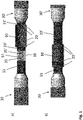
- Figures 1a and 1b illustrates the joining of to power cable ends 30, 30', where figure 1a illustrates the situation just before the ferrule 10 is arranged over the joint central tension elements 35,35'and figure 1b illustrates the situation after the compression ferrule has been arranged over the joint central tension elements but before the compression of the compression ferrule to connect the ferrule to the conductors 33 and 33'.
- the compression ferrule 10 is arranged on a section of the conductor 33' of a first cable end 30'.
- the section is longer than the length of the aperture of the ferrule such that the ferrule can be arranged on the first conductor 33' while the tension elements 35 and 35' are connected.
- the connection 39 is illustrated as straight line in the embodiment shown on the figure, however as discussed above different other connections methods may be used to connect the tension elements.
- the gap between the conductor ends and the connected tension elements are filled with a filler material 37 which can include a second compression ferrule, welding metal and/or a semi-conducting polymer.
- the ferrule 10 has been slid sideways such that the ferrule 10 surrounds the joint between the tension elements and the compression zones 20 indicated on the surface of the ferrule are arranged over the conductors 33 and 33' respectively.
- the ferrule would be compressed onto a first conductor end and the ferrule would be compressed onto a second conductor end. If the ferrule comprises additional compression zones additional compression of the ferrule is performed, preferably the first compressions are preformed closest to the centre of the ferrule and alternating between the two conductor ends.
- the compression tool would preferably compress substantially the full circumference of the compression zone such that any surplus material is moved sideways into the zones not dedicated as compression zones.
- the rebuilding of the semi-conducting and insulating layers around the joint would take place. First a inner semi conducting layer would be applied connecting to the semi-conducting layer of the first and second cable end 30, 30'. Then a layer of insulation would be applied before the outer semi-conducting layer connecting to the outer semi-conducting layers of the first and second cable end 30, 30' is applied.
- Figure 2 illustrates a cross-sectional view of the conductor 33 with a central tension element 35.
- FIG. 3 illustrate the end of a power cable prior to connection to the ferrule.
- the power cable 30 comprises a conductor 33 with a central tension element 35, in the end section to be inserted into the aperture of the ferrule the layers surrounding the conductor har been removed. These layers comprise an inner semi-conducting layer 32, surrounded by an insulation layer 34 and an outer semi-conducting layer 36. From an end section of the central tension element 35 the conductor 33 has been removed.
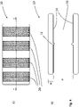
- Figure 4a and 4b show respectively aside view and a cross sectional view of a ferrule 10 according to the present invention.
- the compression zones 20 are marked up.
- the marking is made to assist the installation of the ferrule and the application of the compression force in the intended areas.
- the placement of the compression zones can also be measured out when there are not marked up on the ferrule.
- the marking of the compression zones can as in the illustrated embodiment be done by surface alterations but other alternatives such as colour markings or markings with tape or similar temporarily or permanently added material.
- two compression zones are arranged on either side of the ferrule for compression onto a conductor end to be inserted on either side thereof.
- the ferrule 10 has a longitudinal aperture 16 with a diameter "a".
- the wall thickness is w.
- the internal surface 14 of the wall of the ferrule may comprise corrugations such as threads or small ribs that serve to increase the strength of the connection between the compressed ferrule and the conductor end.
- Figure 5 illustrates an asymmetric ferrule 110 with four compression zones 120.
- the ferrule is for joining two conductors of different cross-section and diameter in that the aperture on the left side is larger than the aperture on the right side, and each adapted to have a diameter that exceeds the diameter of the conductor to be connected only enough to allow for the conductor to be inserted into the aperture.
Landscapes
- Connections Effected By Soldering, Adhesion, Or Permanent Deformation (AREA)
Abstract
Description
- The present invention relates to a subsea power cable, especially a subsea power cable with a j oint. As well as a method for providing such a joint.
- Joining of conductors and power cables may be required both during production and repair of power cables.
- Subsea power cables have a more complex design than overhead lines in that the conductors are surrounded by electrical insulation such as XLPE (cross linked polyethylene) or mass impregnated insulation system. They include elements to handle the subsea environment and elements providing the necessary yield strength to deploy the cable subsea.
- For underground cables - there are limited requirements to mechanical tension properties. These limited requirements are ensured by relying on armour arranged external to the conductor. A conductor joint by welding has reduced mechanical properties compared to the unwelded conductor and is often not sufficiently strong for subsea applications.
- A joint on a subsea cable, especially for power cables without armour arranged external of the conductor, will need to be able to withhold the mechanical tension similar as the force set up when the conductor in the subsea cable is approaching its yield strength and limit.
- Power cables for direct electrical heating (DEH) cannot include metallic/conducting armour external of the conductor as this would have a negative effect on the function of the cable when it is arranged on a pipeline to providing heating of said pipeline. For DEH cables there is a particular need to provide a conductor joint which has a tensional strength and electrical conductivity similar to the conductor.
- If the conductor in it self does not have sufficient tensile strength a tensile strength element can be included in side the conductor.
-
DE1072671 discloses a compression sleeve comprising two concentric layers, where the inner layer provides the electrical connection and the outer layer the tensional strength. The sleeve is compressed with a tool not providing a circular circumference but a circumference with two circle sections and two extending flanges. - The aim of the present invention is to provide a solution for joining a power cable that provides for both an electrical and mechanical connection without relying on external armouring.
- An objective of the present invention is to be able to joint/splice a subsea cable such that the jointed cable has high mechanical tension properties without necessarily using external armour.
- It is the objection to provide a joint that can be made both offshore also during repair and in a factory.
- A further aim is to provide a solution for joining conductors comprising a tension element included therein.
- The present invention provides a power cable comprising a joint, wherein a first conductor end comprising a first tension element is electrically and mechanically connected to a second conductor end with a second tension element, wherein the joint comprises a compression ferrule with a longitudinal aperture, wherein the compression ferrule comprises at least two compression zones that have been compressed respectively onto the first conductor end and the second conductor end inserted into the aperture of the compression ferrule from opposite sides.
- The first and second conductor may comprise one or more tension elements. In one embodiment the tension element is a central tension element arranged in the centre of the conductors.
- The tension element could be made of steel, like a steel rod or wire, or the tension element could be made of fibres such as glass or carbon fibres.
- In one embodiment of the power cable the first tension element and the second tension element are in contact within the aperture. Preferably, the first tension element and the second tension element are mechanically connected within the aperture by welding, by compression, and/or by a second compression ferrule.
- In an embodiment of the power cable the first tension element and the second tension element within the aperture are surrounded by a filler material. Preferably, the filler material is selected from metal in the second compression ferrule, welding metal, and/or a semi-conducting polymer.
- In a further embodiment of the power cable the compression ferrule has a wall thickness prior to compression equivalent to 5-50% of the diameter of the aperture, preferably 15-30%, more preferably 20-25%.
- A typical high voltage power cable conductor has a cross-sectional area of 240,300,400,500,630,800,1000,1200,1400,1600,1800, or 2000 mm2. Typical conductor cross sections for DEH cables are 630, 800, 1000, 1200, 1400 or 1600 mm2. The ferrule can be designed with an aperture adapted to receive any one of such conductors. The ferrule is to be designed such that the aperture is adapted to have a diameter that exceeds the diameter of the conductor to be connected only enough to allow for the conductor to be inserted into the aperture. In this way the diameter of the aperture is adapted to be 0.2 - 5 mm larger than diameter of the conductor to be inserted into it, preferably 1-3 mm, more preferably 1-2 mm.
- Power cable according to any one of the proceeding claims, wherein the first conductor end and the second conductor end have different diameters and the compression ferrule is asymmetric with different aperture diameters at opposite sides prior to compression. When the compression ferrule is asymmetric the radial wall thickness on a first side is equivalent to 10-50% of the diameter of the aperture on the first side, preferably 15-30%, more preferably 20-25%. Similarly, the radial wall thickness on a second side is equivalent to 10-50% of the diameter of the aperture on the second side, preferably 15-30%, more preferably 20-25%.
- In a further embodiment the compression ferrule comprises more than two, such as four, six or eight compression zones that have been compressed respectively onto the first conductor end and the second conductor end. In one embodiment one or more of the compression zones that have been compressed have a polygonal shaped radial circumference, preferably a hexagonal or octagonal shaped radial circumference. The polygonal shaped compression provides increased joining strength. Preferably all compression zones are compressed to have similar polygonal circumference. The compression zones are sections in the longitudinal direction of the compression ferrule that are compressed when the ferrule is installed. The compression zones are separated by sections that are not compressed when the ferrule is installed.
- Further, in the power cable the joint including the compressed ferrule is enclosed in an inner semi-conducting layer, enclosed in an insulation layer, enclosed in an outer semi-conducting layer. Optionally one or more additional external sheaths may be provided.
- In one embodiment the compression ferrule prior to compression comprises an internal surface provided with corrugations such as threads. The corrugations serve to further improve the tensile strength of the connection between the ferrule and a conductor end and the electrical connection therebetween.
- In a further embodiment the compression ferrule comprises an internal flange in proximity of the longitudinal centre of the ferrule.
- The compression ferrule can be made of copper or a copper alloy.
- The present invention further provides a method of providing a joint on a power cable wherein a first conductor end comprising a first tension element is electrically and mechanically connected to a second conductor end with a second tension element, comprising
- removing any semi-conducting or insulating layers from an end section of the first conductor end and the second conductor end
- providing a compression ferrule with a longitudinal aperture, wherein the compression ferrule comprises at least two compression zones
- inserting the first conductor end and the second conductor end into the aperture of the compression ferrule from opposite sides;
- compressing the compression ferrule onto the first conductor end and the second conductor end in the at least two compression zones, such that the first conductor end and the second conductor end are electrically and mechanically connected.
- In one embodiment of the method according to the invention,
removing any semi-conducting or insulating layers from an end section of the first conductor end comprises removing any semi-conducting or insulating layers for a length extending the length of the aperture,
and inserting the first conductor end and the second conductor end into the aperture of the compression ferrule from opposite sides comprises: - arranging the compression ferrule surrounding the length of the first conductor end
- connecting the first tension element to the second tension element by welding or by compressing the tensions elements, or attaching a second compression ferrule to the first tension element and to the second tension element, and
- sliding the compression ferrule towards and onto the second conductor end.
- The method includes connecting the first and second tension elements to each other. When they are welded together the ends are preferably cut at an angle providing a V-shaped grove between the ends of the tension elements that is filed with welding material. Additional welding material may be provided to increase the diameter to be similar to the diameters of the respective conductors, thus filling the gap there between with welding material, alternatively or additionally a semi-conducting polymer may be used to fill any gaps and provide the section including the joint tension elements with the same diameter as the conductors. If a second compression ferrule is compressed to the ends of the tension elements to connect these to each other any gaps are similarly filed with welding material and/or semi-conducting polymer to and provide the section including the joint tension elements with the same diameter as the conductors.
- The term "ferrule" as applied here refers to a sleeve element with a throughgoing longitudinal aperture.
- The present invention will be discussed in further detail with reference to the enclosed drawings, that are provided as illustrations of embodiments thereof.
-
Figure 1a shows a side view of a power cable and a compression ferrule prior to positioning of the compression ferrule over the joint tension elements. -
Figure 1b illustrates side view of a power cable and a ferrule prior to compression of the compression ferrule. -
Figure 2 illustrates a cross-sectional view of a conductor with a tension element. -
Figure 3 illustrates a side view of a power cable. -
Figure 4a shows a side view of a compression ferrule prior to installation. -
Figure 4b illustrates the longitudinal cross-sectional view along A-A offigure 4a . -
Figure 5 illustrates a further embodiment of the ferrule. - The present invention will be discussed in further detail with reference to the enclosed figures.
Figures 1a and 1b illustrates the joining of to power cable ends 30, 30', wherefigure 1a illustrates the situation just before theferrule 10 is arranged over the jointcentral tension elements 35,35'andfigure 1b illustrates the situation after the compression ferrule has been arranged over the joint central tension elements but before the compression of the compression ferrule to connect the ferrule to theconductors 33 and 33'. - As illustrated on
figure 1a thecompression ferrule 10 is arranged on a section of the conductor 33' of a first cable end 30'. The section is longer than the length of the aperture of the ferrule such that the ferrule can be arranged on the first conductor 33' while thetension elements 35 and 35' are connected. Theconnection 39 is illustrated as straight line in the embodiment shown on the figure, however as discussed above different other connections methods may be used to connect the tension elements. The gap between the conductor ends and the connected tension elements are filled with afiller material 37 which can include a second compression ferrule, welding metal and/or a semi-conducting polymer. - On
figure 1b theferrule 10 has been slid sideways such that theferrule 10 surrounds the joint between the tension elements and thecompression zones 20 indicated on the surface of the ferrule are arranged over theconductors 33 and 33' respectively. - To complete the joint the ferrule would be compressed onto a first conductor end and the ferrule would be compressed onto a second conductor end. If the ferrule comprises additional compression zones additional compression of the ferrule is performed, preferably the first compressions are preformed closest to the centre of the ferrule and alternating between the two conductor ends. The compression tool would preferably compress substantially the full circumference of the compression zone such that any surplus material is moved sideways into the zones not dedicated as compression zones. After the compression of the ferrule the rebuilding of the semi-conducting and insulating layers around the joint would take place. First a inner semi conducting layer would be applied connecting to the semi-conducting layer of the first and
second cable end 30, 30'. Then a layer of insulation would be applied before the outer semi-conducting layer connecting to the outer semi-conducting layers of the first andsecond cable end 30, 30' is applied. -
Figure 2 illustrates a cross-sectional view of theconductor 33 with acentral tension element 35. -
Figure 3 illustrate the end of a power cable prior to connection to the ferrule. Thepower cable 30 comprises aconductor 33 with acentral tension element 35, in the end section to be inserted into the aperture of the ferrule the layers surrounding the conductor har been removed. These layers comprise an innersemi-conducting layer 32, surrounded by aninsulation layer 34 and an outersemi-conducting layer 36. From an end section of thecentral tension element 35 theconductor 33 has been removed. -
Figure 4a and 4b show respectively aside view and a cross sectional view of aferrule 10 according to the present invention. Onfigure 4a thecompression zones 20 are marked up. The marking is made to assist the installation of the ferrule and the application of the compression force in the intended areas. The placement of the compression zones can also be measured out when there are not marked up on the ferrule. The marking of the compression zones can as in the illustrated embodiment be done by surface alterations but other alternatives such as colour markings or markings with tape or similar temporarily or permanently added material. In the illustrated embodiment two compression zones are arranged on either side of the ferrule for compression onto a conductor end to be inserted on either side thereof. - Additional features of the
ferrule 10 are illustrated in the cross-sectional view infigure 4b . The ferrule has alongitudinal aperture 16 with a diameter "a". The wall thickness is w. Theinternal surface 14 of the wall of the ferrule may comprise corrugations such as threads or small ribs that serve to increase the strength of the connection between the compressed ferrule and the conductor end. -
Figure 5 illustrates anasymmetric ferrule 110 with fourcompression zones 120. The ferrule is for joining two conductors of different cross-section and diameter in that the aperture on the left side is larger than the aperture on the right side, and each adapted to have a diameter that exceeds the diameter of the conductor to be connected only enough to allow for the conductor to be inserted into the aperture.
Claims (15)
- Power cable comprising a joint, wherein a first conductor end (33) comprising a first tension element (35) is electrically and mechanically connected to a second conductor end (33') with a second tension element (35'), characterised in that the joint comprises a compression ferrule (10) with a longitudinal aperture, wherein the compression ferrule comprises at least two compression zones (20) that have been compressed respectively onto the first conductor end (33) and the second conductor end (33') inserted into the aperture of the compression ferrule from opposite sides.
- Power cable according to claim 1, wherein the first tension element (35) and the second tension element (35') are in contact within the aperture.
- Power cable according to claim 2, wherein the first tension element (35) and the second tension element (35') are mechanically connected within the aperture by welding, by compression, and/or by a second compression ferrule.
- Power cable according any one of the claims 1-3, wherein the first tension element (35) and the second tension element (35') within the aperture are surrounded by a filler material (37).
- Power cable according to claim 4, wherein the filler material (37) is selected from metal in the second compression ferrule, welding metal, and/or a semi-conducting polymer.
- Power cable according to any one of the proceeding claims, wherein the compression ferrule has a wall thickness (w) prior to compression equivalent to 5-50% of the diameter (a) of the aperture, preferably 15-30%, more preferably 20-25%.
- Power cable according to any one of the proceeding claims, wherein the first conductor end (33) and the second conductor end (33') have different diameters and the compression ferrule (110) is asymmetric with different aperture diameters (a) at opposite sides prior to compression.
- Power cable according to any one of the proceeding claims, wherein the compression ferrule comprises four or six compression zones (20) that have been compressed respectively onto the first conductor end (33) and the second conductor end (33').
- Power cable according to any one of the proceeding claims, wherein one or more of the compression zones (20) that have been compressed have a polygonal shaped radial circumference, preferably a hexagonal or octagonal shaped radial circumference.
- Power cable according to any one of the proceeding claims, wherein the joint including the compressed ferrule is enclosed in an inner semi-conducting layer, enclosed in an insulation layer, enclosed in an outer semi-conducting layer.
- Power cable according to any one of the proceeding claims, wherein the compression ferrule (10) prior to compression comprises an internal surface (14) provided with corrugations such as threads.
- Power cable according to any one of the proceeding claims, wherein the compression ferrule (10) comprises an internal flange (12) in proximity of the longitudinal centre of the ferrule.
- Power cable according to any one of the proceeding claims, wherein the compression ferrule (10) is made of copper or a copper alloy.
- Method of providing a joint on a power cable wherein a first conductor end (33) comprising a first tension element (35) is electrically and mechanically connected to a second conductor end (33') with a second tension element (35'), comprising- removing any semi-conducting or insulating layers from an end section of the first conductor end and the second conductor end- providing a compression ferrule (10) with a longitudinal aperture, wherein the compression ferrule comprises at least two compression zones (20)- inserting the first conductor end (33) and the second conductor end (33') into the aperture of the compression ferrule from opposite sides- compressing the compression ferrule onto the first conductor end (33) and the second conductor end (33') in the at least two compression zones, such that the first conductor end (33) and the second conductor end (33') are electrically and mechanically connected.
- Method according to claim 13, wherein
removing any semi-conducting or insulating layers from an end section of the first conductor end comprises removing any semi-conducting or insulating layers for a length extending the length of the aperture,
wherein inserting the first conductor end (33) and the second conductor end (33') into the aperture of the compression ferrule from opposite sides comprises:- arranging the compression ferrule surrounding the length of the first conductor end- connecting the first tension element (35) to the second tension element (35') by welding or by compressing the tensions elements, or attaching a second compression ferrule to the first tension element (35) and to the second tension element (35'), and- sliding the compression ferrule towards and onto the second conductor end.
Priority Applications (1)
| Application Number | Priority Date | Filing Date | Title |
|---|---|---|---|
| EP21305004.0A EP4024618B1 (en) | 2021-01-04 | 2021-01-04 | Underwater power cable with pull and permanent connection |
Applications Claiming Priority (1)
| Application Number | Priority Date | Filing Date | Title |
|---|---|---|---|
| EP21305004.0A EP4024618B1 (en) | 2021-01-04 | 2021-01-04 | Underwater power cable with pull and permanent connection |
Publications (2)
| Publication Number | Publication Date |
|---|---|
| EP4024618A1 true EP4024618A1 (en) | 2022-07-06 |
| EP4024618B1 EP4024618B1 (en) | 2026-07-01 |
Family
ID=74191675
Family Applications (1)
| Application Number | Title | Priority Date | Filing Date |
|---|---|---|---|
| EP21305004.0A Active EP4024618B1 (en) | 2021-01-04 | 2021-01-04 | Underwater power cable with pull and permanent connection |
Country Status (1)
| Country | Link |
|---|---|
| EP (1) | EP4024618B1 (en) |
Cited By (1)
| Publication number | Priority date | Publication date | Assignee | Title |
|---|---|---|---|---|
| NO20231265A1 (en) * | 2023-11-21 | 2025-05-22 | Nexans | Armouring wire clamp joint for a cable system |
Citations (6)
| Publication number | Priority date | Publication date | Assignee | Title |
|---|---|---|---|---|
| DE1072671B (en) | 1953-01-09 | 1960-01-07 | AMP Incorporated, Harrisburg, 'Pa. (V.St.A.) | Press sleeve for connecting two electrical conductors |
| JPH0318210A (en) * | 1989-06-14 | 1991-01-25 | Tokyo Electric Power Co Inc:The | Method of connecting overhead distribution line employing tension member of organic new material |
| JPH099447A (en) * | 1995-06-21 | 1997-01-10 | Fujikura Ltd | Crosslinked polyethylene insulated power cable connection method and connection mold equipment |
| US20150075864A1 (en) * | 2013-09-05 | 2015-03-19 | Nexans | Device for joining hybrid electrical transmission cables |
| US20150200513A1 (en) * | 2012-08-09 | 2015-07-16 | Grupo General Cable Sistemas, S.A. | Method for mechanically and electrically joining electrical conductors |
| CN208142352U (en) * | 2018-06-03 | 2018-11-23 | 国网湖北省电力有限公司荆门供电公司 | A kind of steel-cored aluminium strand fracture connection structure |
-
2021
- 2021-01-04 EP EP21305004.0A patent/EP4024618B1/en active Active
Patent Citations (6)
| Publication number | Priority date | Publication date | Assignee | Title |
|---|---|---|---|---|
| DE1072671B (en) | 1953-01-09 | 1960-01-07 | AMP Incorporated, Harrisburg, 'Pa. (V.St.A.) | Press sleeve for connecting two electrical conductors |
| JPH0318210A (en) * | 1989-06-14 | 1991-01-25 | Tokyo Electric Power Co Inc:The | Method of connecting overhead distribution line employing tension member of organic new material |
| JPH099447A (en) * | 1995-06-21 | 1997-01-10 | Fujikura Ltd | Crosslinked polyethylene insulated power cable connection method and connection mold equipment |
| US20150200513A1 (en) * | 2012-08-09 | 2015-07-16 | Grupo General Cable Sistemas, S.A. | Method for mechanically and electrically joining electrical conductors |
| US20150075864A1 (en) * | 2013-09-05 | 2015-03-19 | Nexans | Device for joining hybrid electrical transmission cables |
| CN208142352U (en) * | 2018-06-03 | 2018-11-23 | 国网湖北省电力有限公司荆门供电公司 | A kind of steel-cored aluminium strand fracture connection structure |
Cited By (2)
| Publication number | Priority date | Publication date | Assignee | Title |
|---|---|---|---|---|
| NO20231265A1 (en) * | 2023-11-21 | 2025-05-22 | Nexans | Armouring wire clamp joint for a cable system |
| NO348895B1 (en) * | 2023-11-21 | 2025-07-07 | Nexans | Armouring wire clamp joint for a cable system |
Also Published As
| Publication number | Publication date |
|---|---|
| EP4024618B1 (en) | 2026-07-01 |
Similar Documents
| Publication | Publication Date | Title |
|---|---|---|
| US9905942B2 (en) | Assemblies and methods for electrical splice connections of cables | |
| EP2238649B1 (en) | Segmented decompression resistant cable splice and method of installation | |
| US10410766B2 (en) | Jointed power cable and method of manufacturing the same | |
| CN104518291A (en) | Jointing device for hybrid electrical cables | |
| US11804314B2 (en) | Processes for making electrical cables | |
| KR102777014B1 (en) | Jointing Structure Of Power Cable | |
| CN106856666B (en) | high voltage power lines | |
| NO20210006A1 (en) | Tension and continuity joint for power cable | |
| KR20190114811A (en) | Asymmetric joint | |
| US2731510A (en) | Overhead electric lines and conductors therefor | |
| EP3879653A1 (en) | Joint system of power cable | |
| US4504695A (en) | Power cable joint | |
| US12300408B2 (en) | Power cable with bimetallic conductor | |
| US20240047956A1 (en) | Jointing system of power cable | |
| EP3926759B1 (en) | Cable assembly and method of joining cables | |
| EP4451492A1 (en) | Adaptive rigid sea joint kit | |
| GB2149981A (en) | A flexible joint interconnecting two high tension power cables | |
| JP2020170642A (en) | Ritz wire branch connection and branch connection method | |
| RU2726866C1 (en) | Coupling for electric cable with wire armour | |
| KR102625957B1 (en) | Connecting Conductor For Connecting Different Conductor, Manufacturing Method Of Connecting Conductor And Conneting Device Of Power Cable | |
| EP3694052B1 (en) | Double-acting high tension compression joint | |
| JPS61138481A (en) | Method of connecting conductor of power cable and joint obtained by the same | |
| EP1325373B1 (en) | A method and a device for ensuring a satisfactory tensile strength when jointing a submarine cable | |
| JP2019071738A (en) | Cable connection structure and manufacturing method of the same | |
| KR20250071204A (en) | Method and assembly for jointing the armours of power cables |
Legal Events
| Date | Code | Title | Description |
|---|---|---|---|
| PUAI | Public reference made under article 153(3) epc to a published international application that has entered the european phase |
Free format text: ORIGINAL CODE: 0009012 |
|
| STAA | Information on the status of an ep patent application or granted ep patent |
Free format text: STATUS: THE APPLICATION HAS BEEN PUBLISHED |
|
| AK | Designated contracting states |
Kind code of ref document: A1 Designated state(s): AL AT BE BG CH CY CZ DE DK EE ES FI FR GB GR HR HU IE IS IT LI LT LU LV MC MK MT NL NO PL PT RO RS SE SI SK SM TR |
|
| STAA | Information on the status of an ep patent application or granted ep patent |
Free format text: STATUS: REQUEST FOR EXAMINATION WAS MADE |
|
| 17P | Request for examination filed |
Effective date: 20230109 |
|
| RBV | Designated contracting states (corrected) |
Designated state(s): AL AT BE BG CH CY CZ DE DK EE ES FI FR GB GR HR HU IE IS IT LI LT LU LV MC MK MT NL NO PL PT RO RS SE SI SK SM TR |
|
| STAA | Information on the status of an ep patent application or granted ep patent |
Free format text: STATUS: EXAMINATION IS IN PROGRESS |
|
| 17Q | First examination report despatched |
Effective date: 20240531 |
|
| GRAP | Despatch of communication of intention to grant a patent |
Free format text: ORIGINAL CODE: EPIDOSNIGR1 |
|
| STAA | Information on the status of an ep patent application or granted ep patent |
Free format text: STATUS: GRANT OF PATENT IS INTENDED |
|
| INTG | Intention to grant announced |
Effective date: 20260331 |
|
| GRAS | Grant fee paid |
Free format text: ORIGINAL CODE: EPIDOSNIGR3 |
|
| GRAA | (expected) grant |
Free format text: ORIGINAL CODE: 0009210 |
|
| STAA | Information on the status of an ep patent application or granted ep patent |
Free format text: STATUS: THE PATENT HAS BEEN GRANTED |
|
| AK | Designated contracting states |
Kind code of ref document: B1 Designated state(s): AL AT BE BG CH CY CZ DE DK EE ES FI FR GB GR HR HU IE IS IT LI LT LU LV MC MK MT NL NO PL PT RO RS SE SI SK SM TR |
|
| REG | Reference to a national code |
Ref country code: CH Ref legal event code: F10 Free format text: ST27 STATUS EVENT CODE: U-0-0-F10-F00 (AS PROVIDED BY THE NATIONAL OFFICE) Effective date: 20260701 Ref country code: GB Ref legal event code: FG4D |
|
| REG | Reference to a national code |
Ref country code: DE Ref legal event code: R096 Ref document number: 602021056393 Country of ref document: DE |
|
| REG | Reference to a national code |
Ref country code: IE Ref legal event code: FG4D |