EP4024611A1 - Radar device - Google Patents
Radar device Download PDFInfo
- Publication number
- EP4024611A1 EP4024611A1 EP20859483.8A EP20859483A EP4024611A1 EP 4024611 A1 EP4024611 A1 EP 4024611A1 EP 20859483 A EP20859483 A EP 20859483A EP 4024611 A1 EP4024611 A1 EP 4024611A1
- Authority
- EP
- European Patent Office
- Prior art keywords
- antenna
- radome
- face
- radar device
- transmission
- Prior art date
- Legal status (The legal status is an assumption and is not a legal conclusion. Google has not performed a legal analysis and makes no representation as to the accuracy of the status listed.)
- Pending
Links
Images



Classifications
-
- G—PHYSICS
- G01—MEASURING; TESTING
- G01S—RADIO DIRECTION-FINDING; RADIO NAVIGATION; DETERMINING DISTANCE OR VELOCITY BY USE OF RADIO WAVES; LOCATING OR PRESENCE-DETECTING BY USE OF THE REFLECTION OR RERADIATION OF RADIO WAVES; ANALOGOUS ARRANGEMENTS USING OTHER WAVES
- G01S7/00—Details of systems according to groups G01S13/00, G01S15/00, G01S17/00
- G01S7/02—Details of systems according to groups G01S13/00, G01S15/00, G01S17/00 of systems according to group G01S13/00
- G01S7/03—Details of HF subsystems specially adapted therefor, e.g. common to transmitter and receiver
- G01S7/038—Feedthrough nulling circuits
-
- G—PHYSICS
- G01—MEASURING; TESTING
- G01S—RADIO DIRECTION-FINDING; RADIO NAVIGATION; DETERMINING DISTANCE OR VELOCITY BY USE OF RADIO WAVES; LOCATING OR PRESENCE-DETECTING BY USE OF THE REFLECTION OR RERADIATION OF RADIO WAVES; ANALOGOUS ARRANGEMENTS USING OTHER WAVES
- G01S13/00—Systems using the reflection or reradiation of radio waves, e.g. radar systems; Analogous systems using reflection or reradiation of waves whose nature or wavelength is irrelevant or unspecified
- G01S13/88—Radar or analogous systems specially adapted for specific applications
- G01S13/93—Radar or analogous systems specially adapted for specific applications for anti-collision purposes
- G01S13/931—Radar or analogous systems specially adapted for specific applications for anti-collision purposes of land vehicles
-
- G—PHYSICS
- G01—MEASURING; TESTING
- G01S—RADIO DIRECTION-FINDING; RADIO NAVIGATION; DETERMINING DISTANCE OR VELOCITY BY USE OF RADIO WAVES; LOCATING OR PRESENCE-DETECTING BY USE OF THE REFLECTION OR RERADIATION OF RADIO WAVES; ANALOGOUS ARRANGEMENTS USING OTHER WAVES
- G01S7/00—Details of systems according to groups G01S13/00, G01S15/00, G01S17/00
- G01S7/02—Details of systems according to groups G01S13/00, G01S15/00, G01S17/00 of systems according to group G01S13/00
- G01S7/027—Constructional details of housings, e.g. form, type, material or ruggedness
-
- H—ELECTRICITY
- H01—ELECTRIC ELEMENTS
- H01Q—ANTENNAS, i.e. RADIO AERIALS
- H01Q1/00—Details of, or arrangements associated with, antennas
- H01Q1/27—Adaptation for use in or on movable bodies
- H01Q1/32—Adaptation for use in or on road or rail vehicles
- H01Q1/3208—Adaptation for use in or on road or rail vehicles characterised by the application wherein the antenna is used
- H01Q1/3233—Adaptation for use in or on road or rail vehicles characterised by the application wherein the antenna is used particular used as part of a sensor or in a security system, e.g. for automotive radar, navigation systems
-
- H—ELECTRICITY
- H01—ELECTRIC ELEMENTS
- H01Q—ANTENNAS, i.e. RADIO AERIALS
- H01Q1/00—Details of, or arrangements associated with, antennas
- H01Q1/42—Housings not intimately mechanically associated with radiating elements, e.g. radome
- H01Q1/422—Housings not intimately mechanically associated with radiating elements, e.g. radome comprising two or more layers of dielectric material
-
- H—ELECTRICITY
- H01—ELECTRIC ELEMENTS
- H01Q—ANTENNAS, i.e. RADIO AERIALS
- H01Q15/00—Devices for reflection, refraction, diffraction or polarisation of waves radiated from an antenna, e.g. quasi-optical devices
- H01Q15/02—Refracting or diffracting devices, e.g. lens, prism
- H01Q15/08—Refracting or diffracting devices, e.g. lens, prism formed of solid dielectric material
-
- H—ELECTRICITY
- H01—ELECTRIC ELEMENTS
- H01Q—ANTENNAS, i.e. RADIO AERIALS
- H01Q19/00—Combinations of primary active antenna elements and units with secondary devices, e.g. with quasi-optical devices, for giving the antenna a desired directional characteristic
- H01Q19/06—Combinations of primary active antenna elements and units with secondary devices, e.g. with quasi-optical devices, for giving the antenna a desired directional characteristic using refracting or diffracting devices, e.g. lens
-
- G—PHYSICS
- G01—MEASURING; TESTING
- G01S—RADIO DIRECTION-FINDING; RADIO NAVIGATION; DETERMINING DISTANCE OR VELOCITY BY USE OF RADIO WAVES; LOCATING OR PRESENCE-DETECTING BY USE OF THE REFLECTION OR RERADIATION OF RADIO WAVES; ANALOGOUS ARRANGEMENTS USING OTHER WAVES
- G01S13/00—Systems using the reflection or reradiation of radio waves, e.g. radar systems; Analogous systems using reflection or reradiation of waves whose nature or wavelength is irrelevant or unspecified
- G01S13/88—Radar or analogous systems specially adapted for specific applications
- G01S13/93—Radar or analogous systems specially adapted for specific applications for anti-collision purposes
- G01S13/931—Radar or analogous systems specially adapted for specific applications for anti-collision purposes of land vehicles
- G01S2013/9327—Sensor installation details
- G01S2013/93271—Sensor installation details in the front of the vehicles
-
- G—PHYSICS
- G01—MEASURING; TESTING
- G01S—RADIO DIRECTION-FINDING; RADIO NAVIGATION; DETERMINING DISTANCE OR VELOCITY BY USE OF RADIO WAVES; LOCATING OR PRESENCE-DETECTING BY USE OF THE REFLECTION OR RERADIATION OF RADIO WAVES; ANALOGOUS ARRANGEMENTS USING OTHER WAVES
- G01S13/00—Systems using the reflection or reradiation of radio waves, e.g. radar systems; Analogous systems using reflection or reradiation of waves whose nature or wavelength is irrelevant or unspecified
- G01S13/88—Radar or analogous systems specially adapted for specific applications
- G01S13/93—Radar or analogous systems specially adapted for specific applications for anti-collision purposes
- G01S13/931—Radar or analogous systems specially adapted for specific applications for anti-collision purposes of land vehicles
- G01S2013/9327—Sensor installation details
- G01S2013/93274—Sensor installation details on the side of the vehicles
-
- G—PHYSICS
- G01—MEASURING; TESTING
- G01S—RADIO DIRECTION-FINDING; RADIO NAVIGATION; DETERMINING DISTANCE OR VELOCITY BY USE OF RADIO WAVES; LOCATING OR PRESENCE-DETECTING BY USE OF THE REFLECTION OR RERADIATION OF RADIO WAVES; ANALOGOUS ARRANGEMENTS USING OTHER WAVES
- G01S13/00—Systems using the reflection or reradiation of radio waves, e.g. radar systems; Analogous systems using reflection or reradiation of waves whose nature or wavelength is irrelevant or unspecified
- G01S13/88—Radar or analogous systems specially adapted for specific applications
- G01S13/93—Radar or analogous systems specially adapted for specific applications for anti-collision purposes
- G01S13/931—Radar or analogous systems specially adapted for specific applications for anti-collision purposes of land vehicles
- G01S2013/9327—Sensor installation details
- G01S2013/93275—Sensor installation details in the bumper area
Definitions
- the present invention relates to a radar device.
- radar devices that detect the surroundings of automobiles have been adopted in order to support drivers and realize automatic driving.
- Such radar devices generally emit radio waves from a transmission antenna, receive the radio waves reflected by a target by a reception antenna provided separately from the transmission antenna, and calculates a position and a speed of the target.
- the radar devices for automobiles are generally installed inside bumpers provided on the front and rear of a vehicle body. Therefore, the radio waves emitted from the transmission antenna are reflected by the bumper and returned to the radar side, and are further reflected by a cover (radome) installed to protect the antenna or an antenna substrate, so that the radio waves emitted from the transmission antenna and the reflected waves may interfere with each other. This causes a disorder in an antenna gain pattern, which leads to a problem that detection performance of the target in the radar device deteriorates.
- PTL 1 discloses a technique in which a first face, which is a face on a side opposing a transmitting antenna section and a receiving antenna section, and a second face on the opposite side, are not parallel in a cover member provided in a radar device so that the influence of interference due to noise of reflected waves is reduced.
- a direction of a radio wave emitted to the front side of a vehicle through the cover member is not horizontal to the ground but has an angle corresponding to an inclination angle of the first face of the cover member, and thus, there is a problem that the detection performance deteriorates, such as the distance at which a target parallel to the ground can be detected becomes short.
- a radio wave emitted from the transmitting antenna section has a predetermined beam width and a side lobe, the radio wave after passing through the cover member contains a component perpendicular to the bumper. Therefore, there is also a problem that the detection performance deteriorates since this component is reflected by the bumper and reflected again on the second face, so that interference between the radio wave emitted from the transmission antenna and the reflected wave occurs.
- a radar device is mounted on a vehicle, and includes: a transmission antenna that radiates a radio wave toward an object; a reception antenna that receives a reflected wave of the radio wave radiated from the transmission antenna and reflected by the object; an antenna substrate that has a mounting face on which the transmission antenna and the reception antenna are mounted; and a radome that covers the transmission antenna and the reception antenna.
- the radome is arranged between a bumper of the vehicle and the antenna substrate. A first face of the radome opposing the antenna substrate and a second face of the radome opposing the bumper have portions that are not parallel to each other.
- the transmission antenna radiates the radio wave at an angle inclined from a direction perpendicular to the mounting face.
- the present invention it is possible to prevent interference between a radio wave emitted from a radar device and a reflected wave, and to avoid deterioration of detection performance.
- Positions, sizes, shapes, ranges, and the like of the respective components illustrated in the drawings do not always indicate actual positions, sizes, shapes, ranges and the like in order to facilitate understanding of the invention. Therefore, the present invention is not necessarily limited to the positions, sizes, shapes, ranges, and the like disclosed in the drawings.
- FIG. 1 is a view illustrating a radar device 1 according to a first embodiment of the present invention.
- FIG. 1(a) is a cross-sectional view taken along line A-A' of the radar device 1 according to the present embodiment
- FIG. 1(b) is a perspective plan view of the radar device 1 according to the present embodiment.
- a transmission antenna 3 and a reception antenna 4 are mounted on an antenna substrate 5 in the radar device 1 of the present embodiment.
- the transmission antenna 3 radiates a radio wave toward a target object
- the reception antenna 4 receives a reflected wave of the radio wave radiated from the transmission antenna 3 and reflected by the target object.
- each of the transmission antenna 3 and the reception antenna 4 is configured using an array antenna in which a plurality of antenna elements are arranged side by side in a straight line.
- the transmission antenna 3 and the reception antenna 4 may be configured using an antenna other than the array antenna.
- the transmission antenna 3 is connected with a transmission circuit 6 that sends a modulated signal to the transmission antenna 3 and radiates the radio wave to the transmission antenna 3.
- the reception antenna 4 is connected with a reception circuit 7 that amplifies and demodulates the reflected wave from the target received by the reception antenna 4 to generate a reception signal, and a signal processing circuit 8 that calculates a position and a speed of the target from the reception signal.
- a cover (radome) 2 configured to protect the transmission antenna 3 and the reception antenna 4 is installed so as to cover these antennas in the radar device 1 of the present embodiment.
- the radome 2 is made of a material that transmits the radio wave, such as a resin. Note that FIG. 1(b) illustrates the transmission antenna 3, the reception antenna 4, and the antenna substrate 5 seen through a part of the radome 2 such that an internal structure of the radar device 1 can be understood.
- the radome 2 is arranged between a bumper 9 of the vehicle on which the radar device 1 is mounted and the antenna substrate 5 of the radar device 1 as illustrated in FIG. 1(a) .
- a direction of a y-axis in FIGS. 1(a) and 1(b) corresponds to an up-down direction of the vehicle.
- directions of an x-axis and a z-axis correspond to directions horizontal to a road surface on which the vehicle is traveling.
- the transmission antenna 3 and the reception antenna 4 are arranged side by side in the x-axis direction on a mounting face of the antenna substrate 5 as illustrated in FIG. 1(b) . That is, the transmission antenna 3 and the reception antenna 4 are arranged side by side in the direction horizontal to the road surface on which the vehicle travels.
- the radome 2 is a face (hereinafter referred to as "first face") 2a that is located inside a space in which the antenna substrate 5 is accommodated and opposes the antenna substrate 5, and a face (hereinafter referred to as "second face”) 2b that is located outside the space in which the antenna substrate 5 is accommodated and opposes the bumper 9.
- the first face 2a is parallel to the y-axis and the second face 2b has an angle with respect to the y-axis. That is, the first face 2a is parallel to the mounting face of the antenna substrate 5 on which the transmission antenna 3 and the reception antenna 4 are mounted and a face of the bumper 9 on the radome 2 side, but the second face 2b is inclined with respect to these faces. Therefore, the first face 2a and the second face 2b are not parallel to each other.
- the transmission antenna 3 radiates the radio wave to be inclined from the z-axis corresponding to the direction perpendicular to the mounting face of the antenna substrate 5.
- a radiated radio wave 40a from the transmission antenna 3 is refracted at each of the first face 2a and the second face 2b, which are interfaces between the radome 2 and the air, at the time of passing through the radome 2 so that a propagation direction thereof changes. Then, the radio wave is emitted toward the target object as a transmission wave 40b from the radar device 1.
- each of the angles of the first face 2a and the second face 2b is set such that the propagation direction of the transmission wave 40b from the radar device 1, which has been radiated from the transmission antenna 3 and passed through the radome 2, coincides with the z-axis direction.
- the inclination angle of the second face 2b with respect to the mounting face of the antenna substrate 5 is set such that the propagation direction of the transmission wave 40b coincides with the z-axis direction in consideration of the angle of the radiated radio wave 40a from the transmission antenna 3 and a relative permittivity of the radome 2 at a frequency of the radiated radio wave 40a when the first face 2a is parallel to the mounting face of the antenna substrate 5 as illustrated in FIG. 1(a) .
- FIG. 2 is a view illustrating an example of mounting the radar device 1 on an automobile.
- the radar device 1 is mounted in order to detect an obstacle or the like existing in the left front of a vehicle 100, which is an automobile, at a position illustrated in FIG. 2 , for example, with the z-axis directed to the left-diagonal forward direction of the vehicle 100.
- the radar device 1 is installed inside the bumper 9 in order to avoid contact with the obstacle and the influence of a rear-end collision.
- FIG. 2 illustrates an example of a mounting position of the radar device 1 in the vehicle 100, and the radar device 1 may be mounted at another position. In addition, a plurality of the radar devices 1 may be mounted at different positions in the vehicle 100.
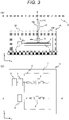
- FIG. 3 is a view illustrating a radar device 10 according to a comparative example.
- FIG. 3(a) is a cross-sectional view taken along line A-A' of the radar device 10 according to the comparative example
- FIG. 3(b) is a perspective plan view of the radar device 10 according to the comparative example.
- FIG. 3(a) is a cross-sectional view taken along line A-A' of the radar device 10 according to the comparative example
- FIG. 3(b) is a perspective plan view of the radar device 10 according to the comparative example.
- the radome 2 has a first face 20a that is located inside a space in which the antenna substrate 5 is accommodated and opposes the antenna substrate 5, and a second face 20b that is located outside the space in which the antenna substrate 5 is accommodated and opposes the bumper 9 in the radar device 10, and these faces are parallel to the antenna substrate 5.
- the transmission antenna 3 radiates a radio wave in the z-axis direction.
- the same structure as the radar device 1 illustrated in FIG. 1 is provided other than the above.
- the radar device 10 of the comparative example illustrated in FIG. 3 when the radiated radio wave 40a from the transmission antenna 3 passes through the radome 20 and is emitted in the z-axis direction as the transmission wave 40b from the radar device 1, a part of the transmission wave 40b is reflected by the bumper 9 and returns to the opposite side in the z-axis direction as a reflected wave 41. A part of the reflected wave 41 from the bumper 9 is reflected again on the second face 20b of the radome 20 and propagates as a re-reflected wave 42 from the radome 20 in the same z-axis direction as the transmission wave 40b. As a result, interference occurs between the transmission wave 40b and the re-reflected wave 42, and the target detection performance of the radar device 10 deteriorates.
- the rest of the reflected wave 41 by the bumper 9 passes through the radome 20 and is reflected again by the antenna substrate 5. Since a re-reflected wave 43 from the antenna substrate 5 also propagates in the same z-axis direction as the transmission wave 40b, interference occurs between the transmission wave 40b and the re-reflected wave 43, and the target detection performance of the radar device 10 deteriorates.
- the reflected wave 41 from the bumper 9 returns to the opposite side in the z-axis direction in the radar device 10 of the comparative example, so that each of the re-reflected waves 42 and 43 propagating in the same direction as the transmission wave 40b of the radar device 10 is generated in the radome 20 and the antenna substrate 5. As a result, characteristics of the radar device 10 deteriorate.
- the radiated radio wave 40a radiated from the transmission antenna 3 to be inclined from the z-axis is refracted at the first face 2a and the second face 2b, which are the interfaces between the radome 2 and the air, at the time of passing through the radome 2, so that a propagation direction thereof is changed as described above in the radar device 1 of the present embodiment illustrated in FIG. 1 .
- the transmission wave 40b from the radar device 1 is emitted in the z-axis direction.
- a part of this transmission wave 40b is reflected by the bumper 9 and returns to the opposite side in the z-axis direction as the reflected wave 41.
- a part of the reflected wave 41 from the bumper 9 is reflected again on the second face 2b of the radome 2, but the second face 2b has the angle with respect to the y-axis and is not parallel to the bumper 9, and thus, the re-reflected wave 42 from the radome 2 propagates in a direction shifted from the z-axis direction. As a result, no interference occurs between the transmission wave 40b and the re-reflected wave 42.
- the rest of the reflected wave 41 from the bumper 9 is refracted at each of the second face 2b and the first face 2a to be changed in propagation direction at the time of passing through the radome 2 again, and reaches the antenna substrate 5 at an angle with respect to the z-axis.
- This propagation direction of the re-reflected wave 43 of the radio wave being reflected again by the antenna substrate 5 and the propagation direction of the radiated radio wave 40a from the transmission antenna 3 are symmetrical with respect to the z-axis. As a result, no interference occurs between the transmission wave 40b of the radiated radio wave 40a passing through the radome 2 and the re-reflected wave 43.
- the cross-sectional shape of the radome 2 is the trapezoid as illustrated in FIG. 1 has been described in the first embodiment of the present invention described above, but the cross-sectional shape of the radome 2 in the present invention is not limited to the trapezoid.
- the cross-sectional shape of the radome 2 can be any shape as long as the first face 2a opposing the antenna substrate 5 and the second face 2b opposing the bumper 9 are formed in shapes having portions that are not parallel to each other such that at least a part of the second face 2b opposing the bumper 9 is not parallel to the y-axis and a propagation direction of the transmission wave 40b passing through the radome 2 of the radiated radio wave 40a radiated from the transmission antenna 3 at an angle with respect to the z-axis is substantially the same as the z-axis direction.
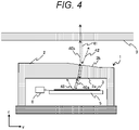
- FIG. 4 is a view illustrating a modification of the radar device 1 according to the first embodiment of the present invention.
- FIG. 4 illustrates a cross-sectional view of the radome 2 having a cross-sectional shape different from that of FIG. 1(a) as the modification of the radar device 1 according to the present embodiment.
- this modification in the second face 2b opposing the bumper 9 in the radome 2, only a range through which the radiated radio wave 40a from the transmission antenna 3 passes has an angle with respect to the y-axis.
- a shape of the radome 2 may be set such that the first face 2a of the radome 2 opposing the antenna substrate 5 has an inclination with respect to the y-axis, that is, the mounting face of the antenna substrate 5.
- an angle difference between the second face 2b opposing the bumper 9 of the radome 2 and the y-axis can be made larger, and it is possible to further reduce the interference between the transmission wave 40b and the re-reflected wave 42 from the radome 2.
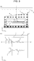
- FIG. 5 is a view illustrating the radar device 1 according to a second embodiment of the present invention.
- FIG. 5(a) is a cross-sectional view taken along line B-B' of the radar device 1 according to the present embodiment
- FIG. 5(b) is a perspective plan view of the radar device 1 according to the present embodiment.
- a radiation direction of the radiated radio wave 40a from the transmission antenna 3, described with reference to FIG. 1 in the first embodiment, and an incident direction of a reception wave 44 when a reflected wave from a target object passes through the radome 2 and is incident on the reception antenna 4 have angles different from each other.
- a cross-sectional shape of the radome 2 is different between a position directly above the transmission antenna 3 and a position directly above the reception antenna 4 in the radar device 1 of the present embodiment.
- the cross-sectional shape is the same as that illustrated in FIG. 1(a) in the first embodiment at the position directly above the transmission antenna 3, and is a cross-sectional shape illustrated in FIG. 5(a) at the position directly above the reception antenna 4.
- inclination directions of these faces with respect to a mounting face of the antenna substrate 5 are different from each other.
- the cross-sectional shape of the radome 2 is different between the position directly above the transmission antenna 3 and the position directly above the reception antenna 4 in the radar device 1 of the present embodiment.
- the radiation direction of the radiated radio wave 40a from the transmission antenna 3 and the incident direction of the reception wave 44 when the transmission wave 40b is reflected by the target object and is incident on the reception antenna 4 can have the angles different from each other at the time of setting a propagation direction of the transmission wave 40b from the radar device 1 to the z-axis direction.
- a coupling between the transmission antenna 3 and the reception antenna 4 can be reduced, and thus, the deterioration of the detection performance of the radar device 1 due to the coupling between the antennas can be reduced.
- the transmission antenna 3 and the reception antenna 4 are arranged side by side in a direction horizontal to a road surface on which the vehicle 100 travels on the mounting face of the antenna substrate 5.
- the radome 2 has the different inclination directions of the second faces 2b and 2c with respect to the mounting face of the antenna substrate 5 at the position directly above the transmission antenna 3 and the position directly above the reception antenna 4.
- the cross-sectional shape of the radome 2 in the present invention is not limited thereto.
- the cross-sectional shape of the radome 2 can be any shape as long as the radiation direction of the radiated radio wave 40a from the transmission antenna 3 and the incident direction of the reception wave 44 when the transmission wave 40b is reflected by the target object and is incident on the reception antenna 4 can have angles different from each other at the time of setting the propagation direction of the transmission wave 40b from the radar device 1 to the z-axis direction.
- FIG. 6 is a view illustrating a modification of the radar device 1 according to the second embodiment of the present invention.
- FIG. 6 illustrates a cross-sectional view of the radome 2 having a cross-sectional shape different from that of FIG. 5(a) as the modification of the radar device 1 according to the present embodiment.
- a cross-sectional shape of the radome 2 can be made the same in the x-axis direction while exhibiting the same operational effects as described above, so that the radome 2 can be easily formed.
- a boundary line between the second faces 2d and 2e is not necessarily the center line 2f of the transmission antenna 3 and the reception antenna 4 in the modification described with reference to FIG. 6 .
- Any boundary line can be set for the second faces 2d and 2e along a direction in which the transmission antenna 3 and the reception antenna 4 are arranged as long as inclinations of the second faces 2d and 2e of the radome 2 opposing the bumper 9 can be made different between the range through which the radiated radio wave 40a from the transmission antenna 3 passes and the range through which the reception wave 44 incident on the reception antenna 4 passes.
Landscapes
- Engineering & Computer Science (AREA)
- Radar, Positioning & Navigation (AREA)
- Remote Sensing (AREA)
- Physics & Mathematics (AREA)
- Computer Networks & Wireless Communication (AREA)
- General Physics & Mathematics (AREA)
- Computer Security & Cryptography (AREA)
- Electromagnetism (AREA)
- Radar Systems Or Details Thereof (AREA)
- Details Of Aerials (AREA)
Abstract
Description
- The present invention relates to a radar device.
- In recent years, radar devices that detect the surroundings of automobiles have been adopted in order to support drivers and realize automatic driving. Such radar devices generally emit radio waves from a transmission antenna, receive the radio waves reflected by a target by a reception antenna provided separately from the transmission antenna, and calculates a position and a speed of the target.
- The radar devices for automobiles are generally installed inside bumpers provided on the front and rear of a vehicle body. Therefore, the radio waves emitted from the transmission antenna are reflected by the bumper and returned to the radar side, and are further reflected by a cover (radome) installed to protect the antenna or an antenna substrate, so that the radio waves emitted from the transmission antenna and the reflected waves may interfere with each other. This causes a disorder in an antenna gain pattern, which leads to a problem that detection performance of the target in the radar device deteriorates.
- As a background art related to the above, for example, the following
PTL 1 is known.PTL 1 discloses a technique in which a first face, which is a face on a side opposing a transmitting antenna section and a receiving antenna section, and a second face on the opposite side, are not parallel in a cover member provided in a radar device so that the influence of interference due to noise of reflected waves is reduced. - PTL 1:
JP 2016-125883 A - In the technique of
PTL 1, a direction of a radio wave emitted to the front side of a vehicle through the cover member is not horizontal to the ground but has an angle corresponding to an inclination angle of the first face of the cover member, and thus, there is a problem that the detection performance deteriorates, such as the distance at which a target parallel to the ground can be detected becomes short. In addition, a radio wave emitted from the transmitting antenna section has a predetermined beam width and a side lobe, the radio wave after passing through the cover member contains a component perpendicular to the bumper. Therefore, there is also a problem that the detection performance deteriorates since this component is reflected by the bumper and reflected again on the second face, so that interference between the radio wave emitted from the transmission antenna and the reflected wave occurs. - A radar device according to the present invention is mounted on a vehicle, and includes: a transmission antenna that radiates a radio wave toward an object; a reception antenna that receives a reflected wave of the radio wave radiated from the transmission antenna and reflected by the object; an antenna substrate that has a mounting face on which the transmission antenna and the reception antenna are mounted; and a radome that covers the transmission antenna and the reception antenna. The radome is arranged between a bumper of the vehicle and the antenna substrate. A first face of the radome opposing the antenna substrate and a second face of the radome opposing the bumper have portions that are not parallel to each other. The transmission antenna radiates the radio wave at an angle inclined from a direction perpendicular to the mounting face.
- According to the present invention, it is possible to prevent interference between a radio wave emitted from a radar device and a reflected wave, and to avoid deterioration of detection performance.
-
- [
FIG. 1] FIG. 1 is a view illustrating a radar device according to a first embodiment of the present invention. - [
FIG. 2] FIG. 2 is a view illustrating an example of mounting the radar device on an automobile. - [
FIG. 3] FIG. 3 is a view illustrating a radar device according to a comparative example. - [
FIG. 4] FIG. 4 is a view illustrating a modification of the radar device according to the first embodiment of the present invention. - [
FIG. 5] FIG. 5 is a view illustrating a radar device according to a second embodiment of the present invention. - [
FIG. 6] FIG. 6 is a view illustrating a modification of the radar device according to the second embodiment of the present invention. - Hereinafter, embodiments of the present invention will be described with reference to the drawings. The following description and drawings are examples given to describe the invention, and are appropriately omitted and simplified for clarification of the description. The present invention can be implemented in various other forms. Each component may be singular or plural unless specifically limited.
- Positions, sizes, shapes, ranges, and the like of the respective components illustrated in the drawings do not always indicate actual positions, sizes, shapes, ranges and the like in order to facilitate understanding of the invention. Therefore, the present invention is not necessarily limited to the positions, sizes, shapes, ranges, and the like disclosed in the drawings.
- When there is a plurality of components having the same or similar functions, the same reference sign will be sometimes described with different subscripts. When it is unnecessary to distinguish between the plurality of components, however, the subscripts will be sometimes omitted in the description.
- Hereinafter, radar devices according to embodiments of the present invention will be described with reference to the drawings.
-
FIG. 1 is a view illustrating aradar device 1 according to a first embodiment of the present invention.FIG. 1(a) is a cross-sectional view taken along line A-A' of theradar device 1 according to the present embodiment, andFIG. 1(b) is a perspective plan view of theradar device 1 according to the present embodiment. - As illustrated in
FIG. 1 , atransmission antenna 3 and areception antenna 4 are mounted on anantenna substrate 5 in theradar device 1 of the present embodiment. Thetransmission antenna 3 radiates a radio wave toward a target object, and thereception antenna 4 receives a reflected wave of the radio wave radiated from thetransmission antenna 3 and reflected by the target object. As illustrated inFIG. 1(b) , for example, each of thetransmission antenna 3 and thereception antenna 4 is configured using an array antenna in which a plurality of antenna elements are arranged side by side in a straight line. Note that thetransmission antenna 3 and thereception antenna 4 may be configured using an antenna other than the array antenna. - The
transmission antenna 3 is connected with atransmission circuit 6 that sends a modulated signal to thetransmission antenna 3 and radiates the radio wave to thetransmission antenna 3. Thereception antenna 4 is connected with areception circuit 7 that amplifies and demodulates the reflected wave from the target received by thereception antenna 4 to generate a reception signal, and asignal processing circuit 8 that calculates a position and a speed of the target from the reception signal. - In addition, a cover (radome) 2 configured to protect the
transmission antenna 3 and thereception antenna 4 is installed so as to cover these antennas in theradar device 1 of the present embodiment. Theradome 2 is made of a material that transmits the radio wave, such as a resin. Note thatFIG. 1(b) illustrates thetransmission antenna 3, thereception antenna 4, and theantenna substrate 5 seen through a part of theradome 2 such that an internal structure of theradar device 1 can be understood. - In the present embodiment, the
radome 2 is arranged between abumper 9 of the vehicle on which theradar device 1 is mounted and theantenna substrate 5 of theradar device 1 as illustrated inFIG. 1(a) . Note that a direction of a y-axis inFIGS. 1(a) and 1(b) corresponds to an up-down direction of the vehicle. In addition, directions of an x-axis and a z-axis correspond to directions horizontal to a road surface on which the vehicle is traveling. Here, thetransmission antenna 3 and thereception antenna 4 are arranged side by side in the x-axis direction on a mounting face of theantenna substrate 5 as illustrated inFIG. 1(b) . That is, thetransmission antenna 3 and thereception antenna 4 are arranged side by side in the direction horizontal to the road surface on which the vehicle travels. - The
radome 2 is a face (hereinafter referred to as "first face") 2a that is located inside a space in which theantenna substrate 5 is accommodated and opposes theantenna substrate 5, and a face (hereinafter referred to as "second face") 2b that is located outside the space in which theantenna substrate 5 is accommodated and opposes thebumper 9. Thefirst face 2a is parallel to the y-axis and thesecond face 2b has an angle with respect to the y-axis. That is, thefirst face 2a is parallel to the mounting face of theantenna substrate 5 on which thetransmission antenna 3 and thereception antenna 4 are mounted and a face of thebumper 9 on theradome 2 side, but thesecond face 2b is inclined with respect to these faces. Therefore, thefirst face 2a and thesecond face 2b are not parallel to each other. - As illustrated in
FIG. 1(a) , thetransmission antenna 3 radiates the radio wave to be inclined from the z-axis corresponding to the direction perpendicular to the mounting face of theantenna substrate 5. Aradiated radio wave 40a from thetransmission antenna 3 is refracted at each of thefirst face 2a and thesecond face 2b, which are interfaces between theradome 2 and the air, at the time of passing through theradome 2 so that a propagation direction thereof changes. Then, the radio wave is emitted toward the target object as atransmission wave 40b from theradar device 1. In the present embodiment, it is preferable to provide a setting such that a gain of thereception antenna 4 is maximized at the same angle as an angle of theradiated radio wave 40a with respect to the z-axis in order to maximize the reception intensity of the reflected wave incident on theradar device 1 by thetransmission wave 40b being reflected from the target object. - In the present embodiment, each of the angles of the
first face 2a and thesecond face 2b is set such that the propagation direction of thetransmission wave 40b from theradar device 1, which has been radiated from thetransmission antenna 3 and passed through theradome 2, coincides with the z-axis direction. Note that the inclination angle of thesecond face 2b with respect to the mounting face of theantenna substrate 5 is set such that the propagation direction of thetransmission wave 40b coincides with the z-axis direction in consideration of the angle of the radiatedradio wave 40a from thetransmission antenna 3 and a relative permittivity of theradome 2 at a frequency of the radiatedradio wave 40a when thefirst face 2a is parallel to the mounting face of theantenna substrate 5 as illustrated inFIG. 1(a) . -
FIG. 2 is a view illustrating an example of mounting theradar device 1 on an automobile. Theradar device 1 is mounted in order to detect an obstacle or the like existing in the left front of avehicle 100, which is an automobile, at a position illustrated inFIG. 2 , for example, with the z-axis directed to the left-diagonal forward direction of thevehicle 100. At this time, theradar device 1 is installed inside thebumper 9 in order to avoid contact with the obstacle and the influence of a rear-end collision. - Note that
FIG. 2 illustrates an example of a mounting position of theradar device 1 in thevehicle 100, and theradar device 1 may be mounted at another position. In addition, a plurality of theradar devices 1 may be mounted at different positions in thevehicle 100. - Next, an effect that the
first face 2a and thesecond face 2b are not parallel to each other in theradome 2 will be described.FIG. 3 is a view illustrating aradar device 10 according to a comparative example.FIG. 3(a) is a cross-sectional view taken along line A-A' of theradar device 10 according to the comparative example, andFIG. 3(b) is a perspective plan view of theradar device 10 according to the comparative example. In the comparative example illustrated inFIG. 3 , theradome 2 has afirst face 20a that is located inside a space in which theantenna substrate 5 is accommodated and opposes theantenna substrate 5, and asecond face 20b that is located outside the space in which theantenna substrate 5 is accommodated and opposes thebumper 9 in theradar device 10, and these faces are parallel to theantenna substrate 5. In addition, thetransmission antenna 3 radiates a radio wave in the z-axis direction. The same structure as theradar device 1 illustrated inFIG. 1 is provided other than the above. - In the
radar device 10 of the comparative example illustrated inFIG. 3 , when the radiatedradio wave 40a from thetransmission antenna 3 passes through theradome 20 and is emitted in the z-axis direction as thetransmission wave 40b from theradar device 1, a part of thetransmission wave 40b is reflected by thebumper 9 and returns to the opposite side in the z-axis direction as a reflectedwave 41. A part of the reflectedwave 41 from thebumper 9 is reflected again on thesecond face 20b of theradome 20 and propagates as are-reflected wave 42 from theradome 20 in the same z-axis direction as thetransmission wave 40b. As a result, interference occurs between thetransmission wave 40b and there-reflected wave 42, and the target detection performance of theradar device 10 deteriorates. - In addition, the rest of the reflected
wave 41 by thebumper 9 passes through theradome 20 and is reflected again by theantenna substrate 5. Since are-reflected wave 43 from theantenna substrate 5 also propagates in the same z-axis direction as thetransmission wave 40b, interference occurs between thetransmission wave 40b and there-reflected wave 43, and the target detection performance of theradar device 10 deteriorates. - As described above, the reflected
wave 41 from thebumper 9 returns to the opposite side in the z-axis direction in theradar device 10 of the comparative example, so that each of there-reflected waves transmission wave 40b of theradar device 10 is generated in theradome 20 and theantenna substrate 5. As a result, characteristics of theradar device 10 deteriorate. - On the other hand, the radiated
radio wave 40a radiated from thetransmission antenna 3 to be inclined from the z-axis is refracted at thefirst face 2a and thesecond face 2b, which are the interfaces between theradome 2 and the air, at the time of passing through theradome 2, so that a propagation direction thereof is changed as described above in theradar device 1 of the present embodiment illustrated inFIG. 1 . As a result, thetransmission wave 40b from theradar device 1 is emitted in the z-axis direction. A part of thistransmission wave 40b is reflected by thebumper 9 and returns to the opposite side in the z-axis direction as the reflectedwave 41. A part of the reflectedwave 41 from thebumper 9 is reflected again on thesecond face 2b of theradome 2, but thesecond face 2b has the angle with respect to the y-axis and is not parallel to thebumper 9, and thus, there-reflected wave 42 from theradome 2 propagates in a direction shifted from the z-axis direction. As a result, no interference occurs between thetransmission wave 40b and there-reflected wave 42. - In addition, the rest of the reflected
wave 41 from thebumper 9 is refracted at each of thesecond face 2b and thefirst face 2a to be changed in propagation direction at the time of passing through theradome 2 again, and reaches theantenna substrate 5 at an angle with respect to the z-axis. This propagation direction of there-reflected wave 43 of the radio wave being reflected again by theantenna substrate 5 and the propagation direction of the radiatedradio wave 40a from thetransmission antenna 3 are symmetrical with respect to the z-axis. As a result, no interference occurs between thetransmission wave 40b of the radiatedradio wave 40a passing through theradome 2 and there-reflected wave 43. - As described above, the
re-reflected waves radome 2 and theantenna substrate 5, respectively, propagate in the directions different from thetransmission wave 40b emitted from theradar device 1 toward the target object in theradar device 1 of the present embodiment. Therefore, it is possible to avoid the interference with thetransmission wave 40b and reduce the deterioration of the characteristics of theradar device 1. - According to the first embodiment of the present invention described above, the following operational effects are achieved.
- (1) The
radar device 1 mounted on thevehicle 100 includes: thetransmission antenna 3 that radiates the radio wave toward the target object; thereception antenna 4 that receives the reflected wave of the radio wave radiated from thetransmission antenna 3 and reflected by the object; theantenna substrate 5 that has the mounting face on which thetransmission antenna 3 and thereception antenna 4 are mounted; and theradome 2 that covers thetransmission antenna 3 and thereception antenna 4. Theradome 2 is arranged between thebumper 9 of thevehicle 100 and theantenna substrate 5. Thefirst face 2a of theradome 2 opposing theantenna substrate 5 and thesecond face 2b of theradome 2 opposing thebumper 9 have portions that are not parallel to each other. Thetransmission antenna 3 radiates the radio wave at the angle from the z-axis direction perpendicular to the mounting face of theantenna substrate 5. Thus, it is possible to prevent the interference between the radio wave emitted from theradar device 1 and the reflected wave, and to avoid the deterioration of the detection performance. - (2) In the
radome 2, each of the angles of thefirst face 2a and thesecond face 2b with respect to the mounting face of theantenna substrate 5 is set such that the propagation direction of thetransmission wave 40b, which is the radio wave radiated from thetransmission antenna 3 and passed through theradome 2, is the z-axis direction substantially perpendicular to the mounting face of theantenna substrate 5. Thus, it is possible to secure the distance at which theradar device 1 can detect the target object and to prevent the deterioration of the detection performance. - (3) As illustrated in
FIG. 1(a) , theradome 2 has a trapezoidal cross-sectional shape in the up-down direction of thevehicle 100, that is, in the y-axis direction. Thus, thefirst face 2a and thesecond face 2b can be made not parallel to each other in theradome 2 with a simple structure that is easy to form. - Note that the example in which the cross-sectional shape of the
radome 2 is the trapezoid as illustrated inFIG. 1 has been described in the first embodiment of the present invention described above, but the cross-sectional shape of theradome 2 in the present invention is not limited to the trapezoid. The cross-sectional shape of theradome 2 can be any shape as long as thefirst face 2a opposing theantenna substrate 5 and thesecond face 2b opposing thebumper 9 are formed in shapes having portions that are not parallel to each other such that at least a part of thesecond face 2b opposing thebumper 9 is not parallel to the y-axis and a propagation direction of thetransmission wave 40b passing through theradome 2 of the radiatedradio wave 40a radiated from thetransmission antenna 3 at an angle with respect to the z-axis is substantially the same as the z-axis direction. -
FIG. 4 is a view illustrating a modification of theradar device 1 according to the first embodiment of the present invention.FIG. 4 illustrates a cross-sectional view of theradome 2 having a cross-sectional shape different from that ofFIG. 1(a) as the modification of theradar device 1 according to the present embodiment. In this modification, in thesecond face 2b opposing thebumper 9 in theradome 2, only a range through which the radiatedradio wave 40a from thetransmission antenna 3 passes has an angle with respect to the y-axis. Thus, it is possible to reduce the thickness of theradome 2 while exhibiting the same effects as described above. - In addition, a shape of the
radome 2 may be set such that thefirst face 2a of theradome 2 opposing theantenna substrate 5 has an inclination with respect to the y-axis, that is, the mounting face of theantenna substrate 5. Thus, an angle difference between thesecond face 2b opposing thebumper 9 of theradome 2 and the y-axis can be made larger, and it is possible to further reduce the interference between thetransmission wave 40b and there-reflected wave 42 from theradome 2. -
FIG. 5 is a view illustrating theradar device 1 according to a second embodiment of the present invention.FIG. 5(a) is a cross-sectional view taken along line B-B' of theradar device 1 according to the present embodiment, andFIG. 5(b) is a perspective plan view of theradar device 1 according to the present embodiment. In theradar device 1 of the present embodiment, a radiation direction of the radiatedradio wave 40a from thetransmission antenna 3, described with reference toFIG. 1 in the first embodiment, and an incident direction of areception wave 44 when a reflected wave from a target object passes through theradome 2 and is incident on thereception antenna 4 have angles different from each other. - Further, a cross-sectional shape of the
radome 2 is different between a position directly above thetransmission antenna 3 and a position directly above thereception antenna 4 in theradar device 1 of the present embodiment. Specifically, the cross-sectional shape is the same as that illustrated inFIG. 1(a) in the first embodiment at the position directly above thetransmission antenna 3, and is a cross-sectional shape illustrated inFIG. 5(a) at the position directly above thereception antenna 4. As a result, on thesecond face 2b of theradome 2 opposing thebumper 9 at the position directly above thetransmission antenna 3 and on asecond face 2c of theradome 2 opposing thebumper 9 at the position directly above thereception antenna 4, inclination directions of these faces with respect to a mounting face of theantenna substrate 5 are different from each other. Note that it is preferable to set an inclination angle of thesecond face 2c at the position directly above thereception antenna 4 with respect to the y-axis such that a gain of thereception antenna 4 is maximized in the incident direction of thereception wave 44. - As described above, the cross-sectional shape of the
radome 2 is different between the position directly above thetransmission antenna 3 and the position directly above thereception antenna 4 in theradar device 1 of the present embodiment. As a result, the radiation direction of the radiatedradio wave 40a from thetransmission antenna 3 and the incident direction of thereception wave 44 when thetransmission wave 40b is reflected by the target object and is incident on thereception antenna 4 can have the angles different from each other at the time of setting a propagation direction of thetransmission wave 40b from theradar device 1 to the z-axis direction. As a result, a coupling between thetransmission antenna 3 and thereception antenna 4 can be reduced, and thus, the deterioration of the detection performance of theradar device 1 due to the coupling between the antennas can be reduced. - According to the second embodiment of the present invention described above, the
transmission antenna 3 and thereception antenna 4 are arranged side by side in a direction horizontal to a road surface on which thevehicle 100 travels on the mounting face of theantenna substrate 5. Theradome 2 has the different inclination directions of the second faces 2b and 2c with respect to the mounting face of theantenna substrate 5 at the position directly above thetransmission antenna 3 and the position directly above thereception antenna 4. Thus, the coupling between thetransmission antenna 3 and thereception antenna 4 can be reduced, and the deterioration of the detection performance of theradar device 1 can be further suppressed. - Note that the example in which the cross-sectional shape of the
radome 2 is made different between the position directly above thetransmission antenna 3 and the position directly above thereception antenna 4 has been described in the second embodiment of the present invention described above, but the cross-sectional shape of theradome 2 in the present invention is not limited thereto. The cross-sectional shape of theradome 2 can be any shape as long as the radiation direction of the radiatedradio wave 40a from thetransmission antenna 3 and the incident direction of thereception wave 44 when thetransmission wave 40b is reflected by the target object and is incident on thereception antenna 4 can have angles different from each other at the time of setting the propagation direction of thetransmission wave 40b from theradar device 1 to the z-axis direction. -
FIG. 6 is a view illustrating a modification of theradar device 1 according to the second embodiment of the present invention.FIG. 6 illustrates a cross-sectional view of theradome 2 having a cross-sectional shape different from that ofFIG. 5(a) as the modification of theradar device 1 according to the present embodiment. In this modification, on asecond face 2d of theradome 2 opposing thebumper 9 in a range through which the radiatedradio wave 40a from thetransmission antenna 3 passes and on asecond face 2e of theradome 2 opposing thebumper 9 in a range through which thereception wave 44 incident on thereception antenna 4 passes, inclination directions of these faces with respect to a mounting face of theantenna substrate 5 are different from each other with acenter line 2f of thetransmission antenna 3 and thereception antenna 4 in the x-axis direction as a boundary. Thus, a cross-sectional shape of theradome 2 can be made the same in the x-axis direction while exhibiting the same operational effects as described above, so that theradome 2 can be easily formed. - Note that a boundary line between the second faces 2d and 2e is not necessarily the
center line 2f of thetransmission antenna 3 and thereception antenna 4 in the modification described with reference toFIG. 6 . Any boundary line can be set for the second faces 2d and 2e along a direction in which thetransmission antenna 3 and thereception antenna 4 are arranged as long as inclinations of the second faces 2d and 2e of theradome 2 opposing thebumper 9 can be made different between the range through which the radiatedradio wave 40a from thetransmission antenna 3 passes and the range through which thereception wave 44 incident on thereception antenna 4 passes. - The above-described respective embodiments and various modifications are merely examples, and the present invention is not limited to these contents unless the features of the invention are impaired. In addition, the various embodiments and modifications have been described as above, but the present invention is not limited to these contents. Other aspects that can be considered within the scope of the technical ideas of the present invention are also included in the scope of the present invention.
- The disclosed content of the following priority application is incorporated herein as the citation.
-
Japanese Patent Application No. 2019-156929 (filed on August 29, 2019 -
- 1
- radar device
- 2
- cover (radome)
- 2a
- first face
- 2b, 2c, 2d, 2e
- second face
- 2f
- center line
- 3
- transmission antenna
- 4
- reception antenna
- 5
- antenna substrate
- 6
- transmission circuit
- 7
- reception circuit
- 8
- signal processing circuit
- 9
- bumper
Claims (5)
- A radar device, mounted on a vehicle, comprising:a transmission antenna that radiates a radio wave toward an object;a reception antenna that receives a reflected wave of the radio wave radiated from the transmission antenna and reflected by the object;an antenna substrate that has a mounting face on which the transmission antenna and the reception antenna are mounted; anda radome that covers the transmission antenna and the reception antenna,wherein the radome is arranged between a bumper of the vehicle and the antenna substrate,a first face of the radome opposing the antenna substrate and a second face of the radome opposing the bumper have portions that are not parallel to each other, andthe transmission antenna radiates the radio wave at an angle inclined from a direction perpendicular to the mounting face.
- The radar device according to claim 1, wherein in the radome, each of angles of the first face and the second face with respect to the mounting face are set such that a propagation direction of the radio wave radiated from the transmission antenna and passed through the radome is a direction substantially perpendicular to the mounting face.
- The radar device according to claim 1 or 2, wherein the radome has a trapezoidal cross-sectional shape in an up-down direction of the vehicle.
- The radar device according to claim 1 or 2, whereinthe transmission antenna and the reception antenna are arranged side by side on the mounting face of the antenna substrate in a direction horizontal to a road surface on which the vehicle travels, andthe radome has different inclination directions of the second face with respect to the mounting face of the antenna substrate at a position directly above the transmission antenna and a position directly above the reception antenna.
- The radar device according to claim 1 or 2, whereinthe transmission antenna and the reception antenna are arranged side by side on the mounting face of the antenna substrate in a direction horizontal to a road surface on which the vehicle travels, andthe radome has different inclination directions of the second face with respect to the mounting face of the antenna substrate, with a boundary line along the direction in which the transmission antenna and the reception antenna are arranged as a boundary.
Applications Claiming Priority (2)
| Application Number | Priority Date | Filing Date | Title |
|---|---|---|---|
| JP2019156929A JP2021032846A (en) | 2019-08-29 | 2019-08-29 | Radar device |
| PCT/JP2020/024043 WO2021039050A1 (en) | 2019-08-29 | 2020-06-18 | Radar device |
Publications (2)
| Publication Number | Publication Date |
|---|---|
| EP4024611A1 true EP4024611A1 (en) | 2022-07-06 |
| EP4024611A4 EP4024611A4 (en) | 2023-08-23 |
Family
ID=74677259
Family Applications (1)
| Application Number | Title | Priority Date | Filing Date |
|---|---|---|---|
| EP20859483.8A Pending EP4024611A4 (en) | 2019-08-29 | 2020-06-18 | RADAR DEVICE |
Country Status (3)
| Country | Link |
|---|---|
| EP (1) | EP4024611A4 (en) |
| JP (1) | JP2021032846A (en) |
| WO (1) | WO2021039050A1 (en) |
Cited By (1)
| Publication number | Priority date | Publication date | Assignee | Title |
|---|---|---|---|---|
| US12339388B2 (en) | 2022-03-30 | 2025-06-24 | Toyoda Gosei Co., Ltd. | Vehicle exterior component and electromagnetic wave radar system |
Families Citing this family (1)
| Publication number | Priority date | Publication date | Assignee | Title |
|---|---|---|---|---|
| CN115911820A (en) * | 2021-09-22 | 2023-04-04 | 安弗施无线射频系统(上海)有限公司 | Antennas and base stations |
Family Cites Families (6)
| Publication number | Priority date | Publication date | Assignee | Title |
|---|---|---|---|---|
| JP2001228238A (en) * | 2000-02-15 | 2001-08-24 | Toyota Motor Corp | Apparatus and method for correcting azimuth axis of electromagnetic wave, radar apparatus, method for correcting azimuth axis, and radome for radar apparatus |
| JP2004015408A (en) * | 2002-06-06 | 2004-01-15 | Oki Electric Ind Co Ltd | Slot array antenna |
| JP6347424B2 (en) * | 2013-06-25 | 2018-06-27 | パナソニックIpマネジメント株式会社 | Wireless module |
| JP6487208B2 (en) * | 2014-12-26 | 2019-03-20 | 株式会社Soken | Radar device and cover member |
| JP2019097118A (en) * | 2017-11-27 | 2019-06-20 | パナソニックIpマネジメント株式会社 | Antenna device |
| JP7626513B2 (en) | 2018-03-09 | 2025-02-07 | 株式会社ニイタカ | Foaming cleaning agent composition and cleaning method |
-
2019
- 2019-08-29 JP JP2019156929A patent/JP2021032846A/en active Pending
-
2020
- 2020-06-18 WO PCT/JP2020/024043 patent/WO2021039050A1/en not_active Ceased
- 2020-06-18 EP EP20859483.8A patent/EP4024611A4/en active Pending
Cited By (1)
| Publication number | Priority date | Publication date | Assignee | Title |
|---|---|---|---|---|
| US12339388B2 (en) | 2022-03-30 | 2025-06-24 | Toyoda Gosei Co., Ltd. | Vehicle exterior component and electromagnetic wave radar system |
Also Published As
| Publication number | Publication date |
|---|---|
| EP4024611A4 (en) | 2023-08-23 |
| WO2021039050A1 (en) | 2021-03-04 |
| JP2021032846A (en) | 2021-03-01 |
Similar Documents
| Publication | Publication Date | Title |
|---|---|---|
| EP2458403B1 (en) | Automotive radar system and method for using same | |
| US10819026B2 (en) | Cover member having curved surfaces, and radar apparatus incorporating the cover member | |
| US10777878B2 (en) | Radome and vehicular radar apparatus comprising same | |
| EP1689030A1 (en) | Vehicle-mounted radar | |
| JP2004325160A (en) | Automotive radar | |
| GB2328748A (en) | Collision avoidance system with sensors mounted on flexible p.c.b. | |
| JP2005156337A (en) | Automotive radar equipment | |
| JP2003240838A (en) | Perimeter monitoring device for vehicles | |
| KR20190058072A (en) | Radar device for vehicle | |
| JP2006029834A (en) | Automotive radar | |
| CN215894947U (en) | Vehicle radar sensor | |
| KR20190004120A (en) | Radar module and automotive radar apparatus having the same | |
| EP4024611A1 (en) | Radar device | |
| JP2007057483A (en) | Millimeter wave radar equipment | |
| KR20180075043A (en) | Radar module and automotive radar apparatus having the same | |
| EP3923020A1 (en) | Radar device | |
| JP7242441B2 (en) | radar equipment | |
| US10637131B2 (en) | Vehicle comprising a rear view mirror and an antenna | |
| US11639993B2 (en) | Radar apparatus | |
| US20240272274A1 (en) | Radar device | |
| JPH10327010A (en) | In-vehicle antenna device | |
| KR20250028872A (en) | Radar apparatus | |
| WO2022044914A1 (en) | Vehicular radar system and vehicle | |
| JP2025122915A (en) | Radar device | |
| JP2005018581A (en) | Inter-vehicle communication vehicle |
Legal Events
| Date | Code | Title | Description |
|---|---|---|---|
| STAA | Information on the status of an ep patent application or granted ep patent |
Free format text: STATUS: THE INTERNATIONAL PUBLICATION HAS BEEN MADE |
|
| PUAI | Public reference made under article 153(3) epc to a published international application that has entered the european phase |
Free format text: ORIGINAL CODE: 0009012 |
|
| STAA | Information on the status of an ep patent application or granted ep patent |
Free format text: STATUS: REQUEST FOR EXAMINATION WAS MADE |
|
| 17P | Request for examination filed |
Effective date: 20220128 |
|
| AK | Designated contracting states |
Kind code of ref document: A1 Designated state(s): AL AT BE BG CH CY CZ DE DK EE ES FI FR GB GR HR HU IE IS IT LI LT LU LV MC MK MT NL NO PL PT RO RS SE SI SK SM TR |
|
| DAV | Request for validation of the european patent (deleted) | ||
| DAX | Request for extension of the european patent (deleted) | ||
| A4 | Supplementary search report drawn up and despatched |
Effective date: 20230726 |
|
| RIC1 | Information provided on ipc code assigned before grant |
Ipc: H01Q 19/06 20060101ALI20230720BHEP Ipc: H01Q 15/08 20060101ALI20230720BHEP Ipc: H01Q 1/32 20060101ALI20230720BHEP Ipc: H04B 1/525 20150101ALI20230720BHEP Ipc: G01S 7/02 20060101ALI20230720BHEP Ipc: G01S 13/931 20200101ALI20230720BHEP Ipc: G01S 7/03 20060101ALI20230720BHEP Ipc: H01Q 1/42 20060101AFI20230720BHEP |
|
| STAA | Information on the status of an ep patent application or granted ep patent |
Free format text: STATUS: EXAMINATION IS IN PROGRESS |
|
| 17Q | First examination report despatched |
Effective date: 20250402 |
|
| RAP3 | Party data changed (applicant data changed or rights of an application transferred) |
Owner name: ASTEMO, LTD. |