EP4024602A1 - Battery and powered apparatus provided with battery - Google Patents
Battery and powered apparatus provided with battery Download PDFInfo
- Publication number
- EP4024602A1 EP4024602A1 EP21779902.2A EP21779902A EP4024602A1 EP 4024602 A1 EP4024602 A1 EP 4024602A1 EP 21779902 A EP21779902 A EP 21779902A EP 4024602 A1 EP4024602 A1 EP 4024602A1
- Authority
- EP
- European Patent Office
- Prior art keywords
- housing
- tab
- side face
- injection
- injection opening
- Prior art date
- Legal status (The legal status is an assumption and is not a legal conclusion. Google has not performed a legal analysis and makes no representation as to the accuracy of the status listed.)
- Pending
Links
Images



Classifications
-
- H—ELECTRICITY
- H01—ELECTRIC ELEMENTS
- H01M—PROCESSES OR MEANS, e.g. BATTERIES, FOR THE DIRECT CONVERSION OF CHEMICAL ENERGY INTO ELECTRICAL ENERGY
- H01M50/00—Constructional details or processes of manufacture of the non-active parts of electrochemical cells other than fuel cells, e.g. hybrid cells
- H01M50/50—Current conducting connections for cells or batteries
- H01M50/543—Terminals
- H01M50/545—Terminals formed by the casing of the cells
-
- H—ELECTRICITY
- H01—ELECTRIC ELEMENTS
- H01M—PROCESSES OR MEANS, e.g. BATTERIES, FOR THE DIRECT CONVERSION OF CHEMICAL ENERGY INTO ELECTRICAL ENERGY
- H01M10/00—Secondary cells; Manufacture thereof
- H01M10/04—Construction or manufacture in general
- H01M10/0413—Large-sized flat cells or batteries for motive or stationary systems with plate-like electrodes
-
- H—ELECTRICITY
- H01—ELECTRIC ELEMENTS
- H01M—PROCESSES OR MEANS, e.g. BATTERIES, FOR THE DIRECT CONVERSION OF CHEMICAL ENERGY INTO ELECTRICAL ENERGY
- H01M10/00—Secondary cells; Manufacture thereof
- H01M10/04—Construction or manufacture in general
- H01M10/0436—Small-sized flat cells or batteries for portable equipment
-
- H—ELECTRICITY
- H01—ELECTRIC ELEMENTS
- H01M—PROCESSES OR MEANS, e.g. BATTERIES, FOR THE DIRECT CONVERSION OF CHEMICAL ENERGY INTO ELECTRICAL ENERGY
- H01M10/00—Secondary cells; Manufacture thereof
- H01M10/05—Accumulators with non-aqueous electrolyte
- H01M10/058—Construction or manufacture
- H01M10/0585—Construction or manufacture of accumulators having only flat construction elements, i.e. flat positive electrodes, flat negative electrodes and flat separators
-
- H—ELECTRICITY
- H01—ELECTRIC ELEMENTS
- H01M—PROCESSES OR MEANS, e.g. BATTERIES, FOR THE DIRECT CONVERSION OF CHEMICAL ENERGY INTO ELECTRICAL ENERGY
- H01M50/00—Constructional details or processes of manufacture of the non-active parts of electrochemical cells other than fuel cells, e.g. hybrid cells
- H01M50/10—Primary casings; Jackets or wrappings
- H01M50/102—Primary casings; Jackets or wrappings characterised by their shape or physical structure
- H01M50/109—Primary casings; Jackets or wrappings characterised by their shape or physical structure of button or coin shape
-
- H—ELECTRICITY
- H01—ELECTRIC ELEMENTS
- H01M—PROCESSES OR MEANS, e.g. BATTERIES, FOR THE DIRECT CONVERSION OF CHEMICAL ENERGY INTO ELECTRICAL ENERGY
- H01M50/00—Constructional details or processes of manufacture of the non-active parts of electrochemical cells other than fuel cells, e.g. hybrid cells
- H01M50/10—Primary casings; Jackets or wrappings
- H01M50/183—Sealing members
- H01M50/186—Sealing members characterised by the disposition of the sealing members
-
- H—ELECTRICITY
- H01—ELECTRIC ELEMENTS
- H01M—PROCESSES OR MEANS, e.g. BATTERIES, FOR THE DIRECT CONVERSION OF CHEMICAL ENERGY INTO ELECTRICAL ENERGY
- H01M50/00—Constructional details or processes of manufacture of the non-active parts of electrochemical cells other than fuel cells, e.g. hybrid cells
- H01M50/10—Primary casings; Jackets or wrappings
- H01M50/183—Sealing members
- H01M50/186—Sealing members characterised by the disposition of the sealing members
- H01M50/188—Sealing members characterised by the disposition of the sealing members the sealing members being arranged between the lid and terminal
-
- H—ELECTRICITY
- H01—ELECTRIC ELEMENTS
- H01M—PROCESSES OR MEANS, e.g. BATTERIES, FOR THE DIRECT CONVERSION OF CHEMICAL ENERGY INTO ELECTRICAL ENERGY
- H01M50/00—Constructional details or processes of manufacture of the non-active parts of electrochemical cells other than fuel cells, e.g. hybrid cells
- H01M50/50—Current conducting connections for cells or batteries
- H01M50/531—Electrode connections inside a battery casing
-
- H—ELECTRICITY
- H01—ELECTRIC ELEMENTS
- H01M—PROCESSES OR MEANS, e.g. BATTERIES, FOR THE DIRECT CONVERSION OF CHEMICAL ENERGY INTO ELECTRICAL ENERGY
- H01M50/00—Constructional details or processes of manufacture of the non-active parts of electrochemical cells other than fuel cells, e.g. hybrid cells
- H01M50/50—Current conducting connections for cells or batteries
- H01M50/543—Terminals
- H01M50/552—Terminals characterised by their shape
- H01M50/559—Terminals adapted for cells having curved cross-section, e.g. round, elliptic or button cells
-
- H—ELECTRICITY
- H01—ELECTRIC ELEMENTS
- H01M—PROCESSES OR MEANS, e.g. BATTERIES, FOR THE DIRECT CONVERSION OF CHEMICAL ENERGY INTO ELECTRICAL ENERGY
- H01M50/00—Constructional details or processes of manufacture of the non-active parts of electrochemical cells other than fuel cells, e.g. hybrid cells
- H01M50/60—Arrangements or processes for filling or topping-up with liquids; Arrangements or processes for draining liquids from casings
- H01M50/609—Arrangements or processes for filling with liquid, e.g. electrolytes
- H01M50/627—Filling ports
Definitions
- This application relates to a battery and an electric apparatus with such battery.
- a battery usually includes a cell, a housing configured to accommodate the cell, and a top cover mounted to the housing.
- the top cover is usually provided with an injection opening, and an electrolyte is injected into the housing from the injection opening.
- the cell includes electrode plates and tabs connected to the electrode plates, where the tabs are configured to achieve electronic conduction.
- the electrolyte is impeded by the electrode plates and the tabs during injection, resulting in low injection efficiency, which in turn affects infiltration efficiency of the electrolyte to the electrode plates.
- This application provides a battery, including a laminated cell, a first housing configured to accommodate the laminated cell, and a second housing mounted to the first housing, where the laminated cell includes an electrode assembly and a first tab.
- the electrode assembly includes a first side face, where the first tab is connected to the first side face, and the first housing, the first tab, and the first side face together define an injection space.
- the second housing is provided with an injection opening, where a projection of the injection space onto the second housing covers at least part of the injection opening.
- a central axis of the injection opening is located inside the injection space.
- the first tab includes a first face closer to the laminated cell, a second face farther away from the laminated cell, and a second side face connected between the first face and the second face.
- the first side face includes a flat region and a cambered region connected to the flat region, where the flat region, the second side face, and the first housing together define the injection space.
- a distance between the second side face and a joint of the flat region and the cambered region is defined as L, and a distance between the central axis of the injection opening and the second side face is less than or equal to 0.5L.
- the distance between the central axis of the injection opening and the second side face ranges from 0.4 mm to 1 mm.
- a sealing piece is provided in the injection opening.
- the second housing is further provided with a through hole, where a pole electrically insulated from the second housing is provided in the through hole.
- the electrode assembly includes a first electrode plate, a separator, and a second electrode plate, where the first tab is connected to the first electrode plate, a second tab is connected to the second electrode plate, the second tab is electrically connected to the pole, and the first tab is electrically connected to the first housing or the second housing.
- the first housing is provided with a through hole, where a pole electrically insulated from the first housing is provided in the through hole, and the first tab is electrically connected to the pole.
- This application further provides an electric apparatus, where the electric apparatus includes the foregoing battery.
- the projection of the injection space onto the second housing covers at least part of the injection opening, so that during injection, electrolyte can bypass the laminated cell and directly flow into the injection space from the injection opening. Therefore, this application can improve injection efficiency, thereby improving infiltration efficiency of the electrolyte to the electrode plates.
- an embodiment of this application provides a battery 100, including a laminated cell 10, a first housing 20 configured to accommodate the laminated cell 10, and a second housing 30 mounted to the first housing 20.
- the laminated cell 10 includes an electrode assembly 11 and a first tab 12.
- the electrode assembly 11 includes a first side face 111, where the first tab 12 is connected to the first side face 111.
- the first housing 20, the first tab 12, and the first side face 111 together define an injection space 101 (as shown in FIG. 4 ).
- the second housing 30 is provided with an injection opening 31, where a projection of the injection space 101 onto the second housing 30 covers at least part of the injection opening 31.
- the projection of the injection space 101 onto the second housing 30 covers at least part of the injection opening 31, so that during injection, electrolyte can bypass the laminated cell 20 and directly flow into the injection space 101 from the injection opening 31. Therefore, this application can improve injection efficiency, thereby improving infiltration efficiency of the electrolyte to electrode plates.
- a central axis A of the injection opening 31 is located inside the injection space 101.
- the injection opening 31 may be in a geometrically symmetric shape, such as a rounded, elliptic, square, or hexagonal shape.
- the central axis A of the injection opening 31 is located inside the injection space 101, such that the projection of the injection space 101 onto the second housing 30 and the injection opening 31 have a larger overlapping area, further ensuring that the electrolyte is not impeded by the laminated cell 10 during injection.
- the injection opening 31 may be in other asymmetric shapes, which is not limited in this application.
- the injection opening 31 may be formed by stamping, mechanical cutting, or the like.
- the first tab 12 includes a first face 121 closer to the laminated cell 10, a second face 122 farther away from the laminated cell 10, and a second side face 123 connected between the first face 121 and the second face 122.
- the first side face 111 includes a flat region 1110 and a cambered region 1111 connected to the flat region 1110, where the flat region 1110, the second side face 123, and the first housing 20 together define the injection space 101.
- a cross section of the injection space 101 is roughly triangular. Therefore, a region of the injection space 101 closer to the first tab 12 is larger than a region of the injection space 101 farther away from the first tab 12.
- a distance between the second side face 123 and a joint of the flat region 1110 and the cambered region 1111 is defined as L, and a distance between the central axis A of the injection opening 31 and the second side face 123 is less than or equal to 0.5L.
- the central axis A of the injection opening 31 is closer to the first tab 12, such that electrolyte flows into a region with a larger cross section in the injection space 101 during injection, further ensuring that the electrolyte is not impeded by the laminated cell 10 during injection.
- the distance between the central axis A of the injection opening 31 and the second side face 123 ranges from 0.4 mm to 1 mm.
- a sealing piece 32 is provided in the injection opening 31. After injection is completed, the injection opening 31 is sealed by using the sealing piece 32, preventing the injected electrolyte from spilling over or preventing external impurities from entering the battery 100.
- the sealing piece 32 is made of elastic materials.
- the sealing piece 32 is fastened into the injection opening 31 through elastic deformation force generated by stress.
- the sealing piece may alternatively be a sealing nail made of weldable materials (such as stainless steel or aluminum alloy). After the sealing nail is inserted into the injection opening 31, the sealing nail is fastened to the second housing 30 by laser welding. In this way, the injection opening 31 can be reliably sealed.
- the second housing 30 is further provided with a through hole 33, where a pole 34 electrically insulated from the second housing 30 is provided in the through hole 33.
- the pole 34 may be located at the center of the second housing 30.
- the electrode assembly 11 includes a first electrode plate 11a, a second electrode plate 11b, and a separator (not shown in the figure) located between the first electrode plate 11a and the second electrode plate 11b that are stacked, where the first tab 12 is connected to the first electrode plate 11a.
- a second tab 13 is connected to the second electrode plate 11b, the second tab 13 is electrically connected to the pole 34, and the first tab 12 is electrically connected to the first housing 20 or the second housing 30.
- the first tab 11a includes a first current collector and a first active material layer provided on a surface of the first current collector, where the first tab 12 may be electrically connected to the first current collector by welding, and electrically connected to the pole 34 by using a first adapting piece 120.
- the second electrode plate 11b includes a second current collector and a second active material layer provided on a surface of the second current collector, where the second tab 13 may be electrically connected to the second current collector by welding, and electrically connected to the first housing 20 or the second housing 30 by using a second adapting piece 130.
- first housing 20 and the second housing 30 may be made of metal.
- first housing 20 and the second housing 30 may be made of steel alloy, aluminum alloy, iron alloy, copper alloy, nickel alloy, or the like.
- the pole 34 By electrically connecting the first tab 12 to the pole 34, the pole 34 can present the same polarity as the first electrode plate 11a.
- the first housing 20 and the second housing 30 By electrically connecting the second tab 13 to the first housing 20 or the second housing 30, when the first housing 20 and the second housing 30 are fastened by welding, the first housing 20 and the second housing 30 can generally present the same polarity as the second electrode plate 11b; when the first housing 20 and the second housing 30 are fastened by using an insulating pad, the first housing 20 or the second housing 30 can present the same polarity as the second electrode plate 11b.
- the battery 100 in this embodiment is a button cell, and the first housing 20 and the second housing 30 are both made of stainless steel.
- the first housing 20 and the second housing 30 may be made into required shapes by laser cutting, machine tool processing, or other processes.
- the first housing 20 may alternatively be made into a scour hole by stamping forming, so as to accommodate the laminated cell 10.
- some other embodiments of this application further provide a battery 200.
- the difference from the battery 100 is that the pole 34 electrically connected to the first tab 12 is located on the first housing 20.
- the pole 34 is electrically insulated from the first housing 20.
- the pole 34 may be located on a side wall of the first housing 20.
- the second tab 13 is electrically connected to the pole 34.
- the first tab 12 is electrically connected to the first housing 20 or the second housing 30.
- FIG. 7 another embodiment of this application further provides a battery 300.
- the difference from the battery 100 is that no pole is provided on the first housing 20 and the second housing 30.
- the first housing 20 and the second housing 30 are fastened by using a sealing ring (not shown in the figure), that is, the first housing 20 and the second housing 30 are electrically insulated by using the sealing ring.
- the first tab 12 is electrically connected to the second housing 30, and the second tab 13 is electrically connected to the first housing 20.
- this application further provides an electric apparatus 1, where the electric apparatus 1 includes the foregoing battery 100 (or the battery 200 or 300).
- the electric apparatus 1 may be a consumer electronic product (such as a mobile communications apparatus, a tablet computer, or a notebook computer), an electric tool, an unmanned aerial vehicle, an energy storage apparatus, a power apparatus, or the like.
- the electric apparatus 1 is an electric vehicle.
Landscapes
- Chemical & Material Sciences (AREA)
- Chemical Kinetics & Catalysis (AREA)
- Electrochemistry (AREA)
- General Chemical & Material Sciences (AREA)
- Engineering & Computer Science (AREA)
- Manufacturing & Machinery (AREA)
- Sealing Battery Cases Or Jackets (AREA)
- Filling, Topping-Up Batteries (AREA)
- Connection Of Batteries Or Terminals (AREA)
Abstract
Description
- This application relates to a battery and an electric apparatus with such battery.
- A battery usually includes a cell, a housing configured to accommodate the cell, and a top cover mounted to the housing. The top cover is usually provided with an injection opening, and an electrolyte is injected into the housing from the injection opening. The cell includes electrode plates and tabs connected to the electrode plates, where the tabs are configured to achieve electronic conduction.
- However, because the injection opening is located on the top of the cell, the electrolyte is impeded by the electrode plates and the tabs during injection, resulting in low injection efficiency, which in turn affects infiltration efficiency of the electrolyte to the electrode plates.
- In order to address the foregoing shortcomings of the prior art, it is necessary to provide a battery that can improve injection efficiency, so as to improve infiltration efficiency of an electrolyte to electrode plates.
- This application provides a battery, including a laminated cell, a first housing configured to accommodate the laminated cell, and a second housing mounted to the first housing, where the laminated cell includes an electrode assembly and a first tab. The electrode assembly includes a first side face, where the first tab is connected to the first side face, and the first housing, the first tab, and the first side face together define an injection space. The second housing is provided with an injection opening, where a projection of the injection space onto the second housing covers at least part of the injection opening.
- In some embodiments of this application, a central axis of the injection opening is located inside the injection space.
- In some embodiments of this application, the first tab includes a first face closer to the laminated cell, a second face farther away from the laminated cell, and a second side face connected between the first face and the second face. The first side face includes a flat region and a cambered region connected to the flat region, where the flat region, the second side face, and the first housing together define the injection space.
- In some embodiments of this application, a distance between the second side face and a joint of the flat region and the cambered region is defined as L, and a distance between the central axis of the injection opening and the second side face is less than or equal to 0.5L.
- In some embodiments of this application, the distance between the central axis of the injection opening and the second side face ranges from 0.4 mm to 1 mm.
- In some embodiments of this application, a sealing piece is provided in the injection opening.
- In some embodiments of this application, the injection opening, the sealing piece, and the second housing are all rounded, where a distance between a center of the injection opening and a center of the second housing is defined as M, a radius of the second housing is defined as R1, a radius of the sealing piece is defined as R2, and M, R1, and R2 satisfy M=R1-R2-0.2 mm.
- In some embodiments of this application, the second housing is further provided with a through hole, where a pole electrically insulated from the second housing is provided in the through hole.
- In some embodiments of this application, the electrode assembly includes a first electrode plate, a separator, and a second electrode plate, where the first tab is connected to the first electrode plate, a second tab is connected to the second electrode plate, the second tab is electrically connected to the pole, and the first tab is electrically connected to the first housing or the second housing.
- In some embodiments of this application, the first housing is provided with a through hole, where a pole electrically insulated from the first housing is provided in the through hole, and the first tab is electrically connected to the pole.
- This application further provides an electric apparatus, where the electric apparatus includes the foregoing battery.
- In this application, the projection of the injection space onto the second housing covers at least part of the injection opening, so that during injection, electrolyte can bypass the laminated cell and directly flow into the injection space from the injection opening. Therefore, this application can improve injection efficiency, thereby improving infiltration efficiency of the electrolyte to the electrode plates.
-
-
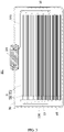
FIG. 1 is a schematic structural exploded view of a battery according to an embodiment of this application. -
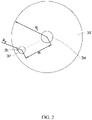
FIG. 2 is a top view of the battery shown inFIG. 1 . -
FIG. 3 is a cross-sectional view of the battery shown inFIG. 1 . -
FIG. 4 is a top view of the battery shown inFIG. 1 without a second housing. -
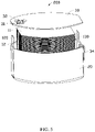
FIG. 5 is a schematic structural exploded view of a battery according to another embodiment of this application. -
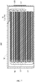
FIG. 6 is a cross-sectional view of the battery shown inFIG. 5 . -
FIG. 7 is a cross-sectional view of a battery according to another embodiment of this application. -
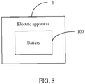
FIG. 8 is a schematic structural diagram of an electric apparatus according to an embodiment of this application. - This application will be further described with reference to the accompanying drawings in the following specific embodiments.
- The following clearly describes the technical solutions in the embodiments of this application with reference to the accompanying drawings in the embodiments of this application. Apparently, the described embodiments are only some rather than all of the embodiments of this application.
- Unless otherwise defined, all technical and scientific terms used herein shall have the same meanings as commonly understood by those skilled in the art to which this application belongs. The terms used herein in the specification of this application are merely intended to describe specific embodiments but not intended to limit this application.
- The following describes in detail some embodiments of this application with reference to the accompanying drawings. In absence of conflicts, the following embodiments and features in the embodiments may be combined.
- Referring to
FIG. 1 to FIG. 4 , an embodiment of this application provides abattery 100, including a laminatedcell 10, afirst housing 20 configured to accommodate the laminatedcell 10, and asecond housing 30 mounted to thefirst housing 20. The laminatedcell 10 includes anelectrode assembly 11 and afirst tab 12. - The
electrode assembly 11 includes afirst side face 111, where thefirst tab 12 is connected to thefirst side face 111. Thefirst housing 20, thefirst tab 12, and thefirst side face 111 together define an injection space 101 (as shown inFIG. 4 ). Thesecond housing 30 is provided with an injection opening 31, where a projection of theinjection space 101 onto thesecond housing 30 covers at least part of the injection opening 31. - In this application, the projection of the
injection space 101 onto thesecond housing 30 covers at least part of the injection opening 31, so that during injection, electrolyte can bypass the laminatedcell 20 and directly flow into theinjection space 101 from theinjection opening 31. Therefore, this application can improve injection efficiency, thereby improving infiltration efficiency of the electrolyte to electrode plates. - As shown in
FIG. 4 , in an embodiment, a central axis A of theinjection opening 31 is located inside theinjection space 101. The injection opening 31 may be in a geometrically symmetric shape, such as a rounded, elliptic, square, or hexagonal shape. The central axis A of theinjection opening 31 is located inside theinjection space 101, such that the projection of theinjection space 101 onto thesecond housing 30 and the injection opening 31 have a larger overlapping area, further ensuring that the electrolyte is not impeded by the laminatedcell 10 during injection. - It can be understood that, in other embodiments, the injection opening 31 may be in other asymmetric shapes, which is not limited in this application. The injection opening 31 may be formed by stamping, mechanical cutting, or the like.
- As shown in
FIG. 4 , in an embodiment, thefirst tab 12 includes afirst face 121 closer to the laminatedcell 10, asecond face 122 farther away from the laminatedcell 10, and asecond side face 123 connected between thefirst face 121 and thesecond face 122. Thefirst side face 111 includes a flat region 1110 and a camberedregion 1111 connected to the flat region 1110, where the flat region 1110, thesecond side face 123, and thefirst housing 20 together define theinjection space 101. As shown inFIG. 4 , a cross section of theinjection space 101 is roughly triangular. Therefore, a region of theinjection space 101 closer to thefirst tab 12 is larger than a region of theinjection space 101 farther away from thefirst tab 12. - In an embodiment, a distance between the
second side face 123 and a joint of the flat region 1110 and thecambered region 1111 is defined as L, and a distance between the central axis A of the injection opening 31 and thesecond side face 123 is less than or equal to 0.5L. In this way, the central axis A of the injection opening 31 is closer to thefirst tab 12, such that electrolyte flows into a region with a larger cross section in theinjection space 101 during injection, further ensuring that the electrolyte is not impeded by the laminatedcell 10 during injection. - Further, the distance between the central axis A of the injection opening 31 and the
second side face 123 ranges from 0.4 mm to 1 mm. - As shown in
FIG. 1 , in an embodiment, asealing piece 32 is provided in the injection opening 31. After injection is completed, the injection opening 31 is sealed by using thesealing piece 32, preventing the injected electrolyte from spilling over or preventing external impurities from entering thebattery 100. The sealingpiece 32 is made of elastic materials. Thesealing piece 32 is fastened into the injection opening 31 through elastic deformation force generated by stress. In other embodiments, the sealing piece may alternatively be a sealing nail made of weldable materials (such as stainless steel or aluminum alloy). After the sealing nail is inserted into the injection opening 31, the sealing nail is fastened to thesecond housing 30 by laser welding. In this way, the injection opening 31 can be reliably sealed. - As shown in
FIG. 2 , in an embodiment, the injection opening 31, the sealingpiece 32, and thesecond housing 30 are all rounded, where a distance between a center of the injection opening 31 and a center of thesecond housing 30 is defined as M, a radius of thesecond housing 30 is defined as R1, a radius of the sealingpiece 32 is defined as R2, and M, R1, and R2 satisfy M=R1-R2-0.2 mm (0.2 mm is wall thickness of thefirst housing 20, and according to the relational formula, the sealingpiece 32 does not affect welding of thefirst housing 20 and the second housing 30). - As shown in
FIG. 1 to FIG. 3 , in an embodiment, thesecond housing 30 is further provided with a throughhole 33, where apole 34 electrically insulated from thesecond housing 30 is provided in the throughhole 33. As shown inFIG. 2 , thepole 34 may be located at the center of thesecond housing 30. - Further, as shown in
FIG. 3 , theelectrode assembly 11 includes afirst electrode plate 11a, asecond electrode plate 11b, and a separator (not shown in the figure) located between thefirst electrode plate 11a and thesecond electrode plate 11b that are stacked, where thefirst tab 12 is connected to thefirst electrode plate 11a. Asecond tab 13 is connected to thesecond electrode plate 11b, thesecond tab 13 is electrically connected to thepole 34, and thefirst tab 12 is electrically connected to thefirst housing 20 or thesecond housing 30. - Specifically, the
first tab 11a includes a first current collector and a first active material layer provided on a surface of the first current collector, where thefirst tab 12 may be electrically connected to the first current collector by welding, and electrically connected to thepole 34 by using afirst adapting piece 120. Thesecond electrode plate 11b includes a second current collector and a second active material layer provided on a surface of the second current collector, where thesecond tab 13 may be electrically connected to the second current collector by welding, and electrically connected to thefirst housing 20 or thesecond housing 30 by using asecond adapting piece 130. - More specifically, the
first housing 20 and thesecond housing 30 may be made of metal. For example, thefirst housing 20 and thesecond housing 30 may be made of steel alloy, aluminum alloy, iron alloy, copper alloy, nickel alloy, or the like. - By electrically connecting the
first tab 12 to thepole 34, thepole 34 can present the same polarity as thefirst electrode plate 11a. By electrically connecting thesecond tab 13 to thefirst housing 20 or thesecond housing 30, when thefirst housing 20 and thesecond housing 30 are fastened by welding, thefirst housing 20 and thesecond housing 30 can generally present the same polarity as thesecond electrode plate 11b; when thefirst housing 20 and thesecond housing 30 are fastened by using an insulating pad, thefirst housing 20 or thesecond housing 30 can present the same polarity as thesecond electrode plate 11b. - As shown in
FIG. 1 andFIG. 3 , thebattery 100 in this embodiment is a button cell, and thefirst housing 20 and thesecond housing 30 are both made of stainless steel. When preparation, thefirst housing 20 and thesecond housing 30 may be made into required shapes by laser cutting, machine tool processing, or other processes. Thefirst housing 20 may alternatively be made into a scour hole by stamping forming, so as to accommodate thelaminated cell 10. - Referring to
FIG. 5 andFIG. 6 , some other embodiments of this application further provide abattery 200. The difference from thebattery 100 is that thepole 34 electrically connected to thefirst tab 12 is located on thefirst housing 20. Thepole 34 is electrically insulated from thefirst housing 20. - More specifically, the
pole 34 may be located on a side wall of thefirst housing 20. Thesecond tab 13 is electrically connected to thepole 34. Thefirst tab 12 is electrically connected to thefirst housing 20 or thesecond housing 30. - Referring to
FIG. 7 , another embodiment of this application further provides abattery 300. The difference from thebattery 100 is that no pole is provided on thefirst housing 20 and thesecond housing 30. Thefirst housing 20 and thesecond housing 30 are fastened by using a sealing ring (not shown in the figure), that is, thefirst housing 20 and thesecond housing 30 are electrically insulated by using the sealing ring. Thefirst tab 12 is electrically connected to thesecond housing 30, and thesecond tab 13 is electrically connected to thefirst housing 20. - Referring to
FIG. 8 , this application further provides anelectric apparatus 1, where theelectric apparatus 1 includes the foregoing battery 100 (or thebattery 200 or 300). Theelectric apparatus 1 may be a consumer electronic product (such as a mobile communications apparatus, a tablet computer, or a notebook computer), an electric tool, an unmanned aerial vehicle, an energy storage apparatus, a power apparatus, or the like. Referring toFIG. 8 , in an embodiment, theelectric apparatus 1 is an electric vehicle. - The foregoing descriptions are merely preferable embodiments of this application, but are not intended to limit this application. Any modification, equivalent replacement, or improvement made without departing from the spirit and principle of this application shall fall within the protection scope of this application.
| |
1 |
| laminated |
10 |
| |
11 |
| |
11a |
| |
11b |
| |
12 |
| |
13 |
| |
20 |
| |
30 |
| injection opening | 31 |
| |
32 |
| through |
33 |
| |
34 |
| |
100, 200, 300 |
| |
101 |
| |
111 |
| |
120 |
| |
121 |
| |
122 |
| |
123 |
| second |
130 |
| flat region | 1110 |
| cambered |
1111 |
| central axis | A |
| distance | L, M |
| radius | R1, R2 |
Claims (11)
- A battery, comprising a laminated cell, a first housing configured to accommodate the laminated cell, and a second housing mounted to the first housing, wherein the laminated cell comprises an electrode assembly and a first tab, characterized in that,the electrode assembly comprises a first side face, wherein the first tab is connected to the first side face, and the first housing, the first tab, and the first side face together define an injection space; andthe second housing is provided with an injection opening, wherein a projection of the injection space onto the second housing covers at least part of the injection opening.
- The battery according to claim 1, characterized in that, a central axis of the injection opening is located inside the injection space.
- The battery according to claim 2, characterized in that, the first tab comprises a first face closer to the laminated cell, a second face farther away from the laminated cell, and a second side face connected between the first face and the second face; and
the first side face comprises a flat region and a cambered region connected to the flat region, wherein the flat region, the second side face, and the first housing together define the injection space. - The battery according to claim 3, characterized in that, a distance between the second side face and a joint of the flat region and the cambered region is defined as L, and a distance between the central axis of the injection opening and the second side face is less than or equal to 0.5L.
- The battery according to claim 4, characterized in that, the distance between the central axis of the injection opening and the second side face ranges from 0.4 mm to 1 mm.
- The battery according to claim 1, characterized in that, a sealing piece is provided in the injection opening.
- The battery according to claim 6, characterized in that, the injection opening, the sealing piece, and the second housing are all rounded, wherein a distance between a center of the injection opening and a center of the second housing is defined as M, a radius of the second housing is defined as R1, a radius of the sealing piece is defined as R2, and M, R1, and R2 satisfy M=R1-R2-0.2 mm.
- The battery according to claim 1, characterized in that, the second housing is further provided with a through hole, wherein a pole electrically insulated from the second housing is provided in the through hole.
- The battery according to claim 8, characterized in that, the electrode assembly comprises a first electrode plate, a second electrode plate, and a separator located between the first electrode plate and the second electrode plate that are stacked, wherein the first tab is connected to the first electrode plate, a second tab is connected to the second electrode plate, the second tab is electrically connected to the pole, and the first tab is electrically connected to the first housing or the second housing.
- The battery according to claim 1, characterized in that, the first housing is provided with a through hole, wherein a pole electrically insulated from the first housing is provided in the through hole, and the first tab is electrically connected to the pole.
- An electric apparatus, characterized in that, the electric apparatus comprises the battery according to any one of claims 1 to 10.
Applications Claiming Priority (2)
| Application Number | Priority Date | Filing Date | Title |
|---|---|---|---|
| CN202020450681.2U CN211605201U (en) | 2020-03-31 | 2020-03-31 | Battery and powered device having the same |
| PCT/CN2021/081374 WO2021197077A1 (en) | 2020-03-31 | 2021-03-17 | Battery and powered apparatus provided with battery |
Publications (2)
| Publication Number | Publication Date |
|---|---|
| EP4024602A1 true EP4024602A1 (en) | 2022-07-06 |
| EP4024602A4 EP4024602A4 (en) | 2024-01-24 |
Family
ID=72583151
Family Applications (1)
| Application Number | Title | Priority Date | Filing Date |
|---|---|---|---|
| EP21779902.2A Pending EP4024602A4 (en) | 2020-03-31 | 2021-03-17 | BATTERY AND POWERED DEVICE PROVIDED WITH THE BATTERY |
Country Status (4)
| Country | Link |
|---|---|
| US (1) | US20220238973A1 (en) |
| EP (1) | EP4024602A4 (en) |
| CN (1) | CN211605201U (en) |
| WO (1) | WO2021197077A1 (en) |
Cited By (1)
| Publication number | Priority date | Publication date | Assignee | Title |
|---|---|---|---|---|
| EP4583215A4 (en) * | 2022-11-10 | 2026-04-22 | Ningde Amperex Technology Ltd | BATTERY AND ELECTRONIC DEVICE |
Families Citing this family (13)
| Publication number | Priority date | Publication date | Assignee | Title |
|---|---|---|---|---|
| CN211605201U (en) * | 2020-03-31 | 2020-09-29 | 宁德新能源科技有限公司 | Battery and powered device having the same |
| WO2021258304A1 (en) * | 2020-06-23 | 2021-12-30 | 宁德新能源科技有限公司 | Battery, electronic device, and battery assembling method |
| CN112331969B (en) * | 2020-11-13 | 2022-09-27 | 河北零点新能源科技有限公司 | Structure for improving multiplying power of lithium battery |
| CN112290131A (en) * | 2020-11-18 | 2021-01-29 | 江门市元熙科技有限公司 | a button battery |
| EP4254613A4 (en) * | 2020-11-26 | 2024-10-09 | Ningde Amperex Technology Limited | ELECTROCHEMICAL APPARATUS AND ELECTRONIC DEVICE |
| CN112582716B (en) * | 2020-12-07 | 2022-07-15 | 宁德新能源科技有限公司 | Battery |
| CN112687994B (en) * | 2020-12-25 | 2022-07-22 | 宁德新能源科技有限公司 | Button cell |
| CN114730977A (en) * | 2021-03-24 | 2022-07-08 | 宁德新能源科技有限公司 | Battery and electronic device having the same |
| CN113394520A (en) * | 2021-06-22 | 2021-09-14 | 厦门海辰新能源科技有限公司 | Laminated lithium battery and assembling method |
| CN113937423A (en) * | 2021-09-30 | 2022-01-14 | 新余赣锋电子有限公司 | Button cell |
| CN114628862A (en) * | 2022-03-24 | 2022-06-14 | 广东国光电子有限公司 | Lithium ion battery and preparation method thereof |
| CN115051122B (en) * | 2022-06-28 | 2026-05-01 | 中创新航科技集团股份有限公司 | Battery cell |
| WO2025252356A1 (en) * | 2024-06-05 | 2025-12-11 | Renata Ag | A battery |
Family Cites Families (11)
| Publication number | Priority date | Publication date | Assignee | Title |
|---|---|---|---|---|
| US7479349B2 (en) * | 2002-12-31 | 2009-01-20 | Cardiac Pacemakers, Inc. | Batteries including a flat plate design |
| CN2739806Y (en) * | 2004-07-23 | 2005-11-09 | 上海比亚迪有限公司 | Cylindrical secondary battery |
| JP5114036B2 (en) * | 2006-09-08 | 2013-01-09 | Necエナジーデバイス株式会社 | Manufacturing method of stacked battery |
| JP2009224173A (en) * | 2008-03-17 | 2009-10-01 | Sumitomo Electric Ind Ltd | battery |
| CN102623650B (en) * | 2012-02-14 | 2014-10-08 | 东莞新能源科技有限公司 | Hard shell lithium ion battery |
| JP2014022337A (en) * | 2012-07-23 | 2014-02-03 | Sharp Corp | Nonaqueous secondary battery and liquid injection method therefor |
| JP6208687B2 (en) * | 2012-12-19 | 2017-10-04 | 三洋電機株式会社 | Cylindrical secondary battery and manufacturing method thereof |
| KR102332446B1 (en) * | 2015-01-14 | 2021-11-29 | 삼성에스디아이 주식회사 | Rechargeable battery and pack of the same |
| JP7055648B2 (en) * | 2018-01-26 | 2022-04-18 | 三洋電機株式会社 | Power storage device |
| CN113097657B (en) * | 2019-09-19 | 2024-05-17 | 宁德新能源科技有限公司 | Battery |
| CN211605201U (en) * | 2020-03-31 | 2020-09-29 | 宁德新能源科技有限公司 | Battery and powered device having the same |
-
2020
- 2020-03-31 CN CN202020450681.2U patent/CN211605201U/en active Active
-
2021
- 2021-03-17 EP EP21779902.2A patent/EP4024602A4/en active Pending
- 2021-03-17 WO PCT/CN2021/081374 patent/WO2021197077A1/en not_active Ceased
-
2022
- 2022-03-30 US US17/708,737 patent/US20220238973A1/en active Pending
Cited By (1)
| Publication number | Priority date | Publication date | Assignee | Title |
|---|---|---|---|---|
| EP4583215A4 (en) * | 2022-11-10 | 2026-04-22 | Ningde Amperex Technology Ltd | BATTERY AND ELECTRONIC DEVICE |
Also Published As
| Publication number | Publication date |
|---|---|
| EP4024602A4 (en) | 2024-01-24 |
| CN211605201U (en) | 2020-09-29 |
| WO2021197077A1 (en) | 2021-10-07 |
| US20220238973A1 (en) | 2022-07-28 |
Similar Documents
| Publication | Publication Date | Title |
|---|---|---|
| US20220238973A1 (en) | Battery and electric apparatus with such battery | |
| CN222883809U (en) | End cap assembly, battery cell, battery and electrical device | |
| EP2733778B1 (en) | Jelly-roll with improved processability and battery cell including same | |
| JP4323465B2 (en) | Secondary battery | |
| US12244025B2 (en) | Secondary battery and battery module | |
| EP3926742B1 (en) | Top cover assembly, secondary battery, battery module and device | |
| EP4322314A1 (en) | Lithium battery and preparation method therefor | |
| US20250158180A1 (en) | Pole, top cover structure, battery, battery module and battery pack | |
| CN219534591U (en) | Single battery and battery pack | |
| US20060068277A1 (en) | Secondary battery | |
| US20240243392A1 (en) | Electrochemical apparatus and electronic apparatus | |
| US20200295317A1 (en) | Secondary battery, battery module and vehicle | |
| CN218997009U (en) | Battery cells, batteries and electrical devices | |
| EP4564550A1 (en) | Battery, battery module and electric device | |
| CN217719894U (en) | Check ring, battery cell, battery and power utilization device | |
| CN218919213U (en) | Battery cell, battery and electricity utilization device | |
| US20220399616A1 (en) | Electrochemical device and electronic device | |
| CN116053670A (en) | Battery cover, battery, battery pack and energy storage equipment | |
| CN218101629U (en) | Current collectors, batteries, battery packs and electrical equipment | |
| CN221226504U (en) | Connecting piece and square lithium ion battery | |
| CN223843014U (en) | Secondary batteries, battery packs and electronic devices | |
| CN222380700U (en) | Secondary battery, battery pack, and electronic device | |
| US20250246723A1 (en) | Housing, battery cell, battery, and electric device | |
| CN223092972U (en) | Battery, battery pack and electric equipment | |
| CN223665636U (en) | Secondary batteries, battery packs and electronic devices |
Legal Events
| Date | Code | Title | Description |
|---|---|---|---|
| STAA | Information on the status of an ep patent application or granted ep patent |
Free format text: STATUS: THE INTERNATIONAL PUBLICATION HAS BEEN MADE |
|
| PUAI | Public reference made under article 153(3) epc to a published international application that has entered the european phase |
Free format text: ORIGINAL CODE: 0009012 |
|
| STAA | Information on the status of an ep patent application or granted ep patent |
Free format text: STATUS: REQUEST FOR EXAMINATION WAS MADE |
|
| 17P | Request for examination filed |
Effective date: 20220328 |
|
| AK | Designated contracting states |
Kind code of ref document: A1 Designated state(s): AL AT BE BG CH CY CZ DE DK EE ES FI FR GB GR HR HU IE IS IT LI LT LU LV MC MK MT NL NO PL PT RO RS SE SI SK SM TR |
|
| DAV | Request for validation of the european patent (deleted) | ||
| DAX | Request for extension of the european patent (deleted) | ||
| A4 | Supplementary search report drawn up and despatched |
Effective date: 20231221 |
|
| RIC1 | Information provided on ipc code assigned before grant |
Ipc: H01M 10/04 20060101ALI20231218BHEP Ipc: H01M 50/545 20210101ALI20231218BHEP Ipc: H01M 50/531 20210101ALI20231218BHEP Ipc: H01M 50/188 20210101ALI20231218BHEP Ipc: H01M 50/102 20210101ALI20231218BHEP Ipc: H01M 50/627 20210101AFI20231218BHEP |
|
| GRAP | Despatch of communication of intention to grant a patent |
Free format text: ORIGINAL CODE: EPIDOSNIGR1 |
|
| STAA | Information on the status of an ep patent application or granted ep patent |
Free format text: STATUS: GRANT OF PATENT IS INTENDED |
|
| RIC1 | Information provided on ipc code assigned before grant |
Ipc: H01M 50/627 20210101AFI20251223BHEP Ipc: H01M 50/102 20210101ALI20251223BHEP Ipc: H01M 50/188 20210101ALI20251223BHEP Ipc: H01M 50/531 20210101ALI20251223BHEP Ipc: H01M 50/545 20210101ALI20251223BHEP Ipc: H01M 10/04 20060101ALI20251223BHEP Ipc: H01M 50/109 20210101ALI20251223BHEP Ipc: H01M 50/559 20210101ALI20251223BHEP |
|
| INTG | Intention to grant announced |
Effective date: 20260121 |
|
| GRAS | Grant fee paid |
Free format text: ORIGINAL CODE: EPIDOSNIGR3 |
|
| GRAA | (expected) grant |
Free format text: ORIGINAL CODE: 0009210 |
|
| STAA | Information on the status of an ep patent application or granted ep patent |
Free format text: STATUS: THE PATENT HAS BEEN GRANTED |