EP4024566A1 - Battery module having structure capable of rapid cooling, and ess comprising same - Google Patents
Battery module having structure capable of rapid cooling, and ess comprising same Download PDFInfo
- Publication number
- EP4024566A1 EP4024566A1 EP21760150.9A EP21760150A EP4024566A1 EP 4024566 A1 EP4024566 A1 EP 4024566A1 EP 21760150 A EP21760150 A EP 21760150A EP 4024566 A1 EP4024566 A1 EP 4024566A1
- Authority
- EP
- European Patent Office
- Prior art keywords
- battery module
- cover
- cell stack
- battery
- module according
- Prior art date
- Legal status (The legal status is an assumption and is not a legal conclusion. Google has not performed a legal analysis and makes no representation as to the accuracy of the status listed.)
- Pending
Links
Images



Classifications
-
- H—ELECTRICITY
- H01—ELECTRIC ELEMENTS
- H01M—PROCESSES OR MEANS, e.g. BATTERIES, FOR THE DIRECT CONVERSION OF CHEMICAL ENERGY INTO ELECTRICAL ENERGY
- H01M10/00—Secondary cells; Manufacture thereof
- H01M10/60—Heating or cooling; Temperature control
- H01M10/65—Means for temperature control structurally associated with the cells
- H01M10/656—Means for temperature control structurally associated with the cells characterised by the type of heat-exchange fluid
- H01M10/6567—Liquids
- H01M10/6568—Liquids characterised by flow circuits, e.g. loops, located externally to the cells or cell casings
-
- H—ELECTRICITY
- H01—ELECTRIC ELEMENTS
- H01M—PROCESSES OR MEANS, e.g. BATTERIES, FOR THE DIRECT CONVERSION OF CHEMICAL ENERGY INTO ELECTRICAL ENERGY
- H01M10/00—Secondary cells; Manufacture thereof
- H01M10/60—Heating or cooling; Temperature control
- H01M10/62—Heating or cooling; Temperature control specially adapted for specific applications
- H01M10/627—Stationary installations, e.g. power plant buffering or backup power supplies
-
- A—HUMAN NECESSITIES
- A62—LIFE-SAVING; FIRE-FIGHTING
- A62C—FIRE-FIGHTING
- A62C3/00—Fire prevention, containment or extinguishing specially adapted for particular objects or places
- A62C3/16—Fire prevention, containment or extinguishing specially adapted for particular objects or places in electrical installations, e.g. cableways
-
- A—HUMAN NECESSITIES
- A62—LIFE-SAVING; FIRE-FIGHTING
- A62C—FIRE-FIGHTING
- A62C2/00—Fire prevention or containment
- A62C2/06—Physical fire-barriers
-
- A—HUMAN NECESSITIES
- A62—LIFE-SAVING; FIRE-FIGHTING
- A62C—FIRE-FIGHTING
- A62C2/00—Fire prevention or containment
- A62C2/06—Physical fire-barriers
- A62C2/065—Physical fire-barriers having as the main closure device materials, whose characteristics undergo an irreversible change under high temperatures, e.g. intumescent
-
- A—HUMAN NECESSITIES
- A62—LIFE-SAVING; FIRE-FIGHTING
- A62C—FIRE-FIGHTING
- A62C35/00—Permanently-installed equipment
- A62C35/58—Pipe-line systems
- A62C35/60—Pipe-line systems wet, i.e. containing extinguishing material even when not in use
-
- A—HUMAN NECESSITIES
- A62—LIFE-SAVING; FIRE-FIGHTING
- A62C—FIRE-FIGHTING
- A62C35/00—Permanently-installed equipment
- A62C35/58—Pipe-line systems
- A62C35/68—Details, e.g. of pipes or valve systems
-
- A—HUMAN NECESSITIES
- A62—LIFE-SAVING; FIRE-FIGHTING
- A62C—FIRE-FIGHTING
- A62C37/00—Control of fire-fighting equipment
- A62C37/08—Control of fire-fighting equipment comprising an outlet device containing a sensor, or itself being the sensor, i.e. self-contained sprinklers
- A62C37/10—Releasing means, e.g. electrically released
- A62C37/11—Releasing means, e.g. electrically released heat-sensitive
- A62C37/12—Releasing means, e.g. electrically released heat-sensitive with fusible links
-
- A—HUMAN NECESSITIES
- A62—LIFE-SAVING; FIRE-FIGHTING
- A62C—FIRE-FIGHTING
- A62C37/00—Control of fire-fighting equipment
- A62C37/08—Control of fire-fighting equipment comprising an outlet device containing a sensor, or itself being the sensor, i.e. self-contained sprinklers
- A62C37/10—Releasing means, e.g. electrically released
- A62C37/11—Releasing means, e.g. electrically released heat-sensitive
- A62C37/14—Releasing means, e.g. electrically released heat-sensitive with frangible vessels
-
- H—ELECTRICITY
- H01—ELECTRIC ELEMENTS
- H01M—PROCESSES OR MEANS, e.g. BATTERIES, FOR THE DIRECT CONVERSION OF CHEMICAL ENERGY INTO ELECTRICAL ENERGY
- H01M10/00—Secondary cells; Manufacture thereof
- H01M10/60—Heating or cooling; Temperature control
- H01M10/61—Types of temperature control
- H01M10/613—Cooling or keeping cold
-
- H—ELECTRICITY
- H01—ELECTRIC ELEMENTS
- H01M—PROCESSES OR MEANS, e.g. BATTERIES, FOR THE DIRECT CONVERSION OF CHEMICAL ENERGY INTO ELECTRICAL ENERGY
- H01M10/00—Secondary cells; Manufacture thereof
- H01M10/60—Heating or cooling; Temperature control
- H01M10/65—Means for temperature control structurally associated with the cells
- H01M10/656—Means for temperature control structurally associated with the cells characterised by the type of heat-exchange fluid
- H01M10/6567—Liquids
-
- H—ELECTRICITY
- H01—ELECTRIC ELEMENTS
- H01M—PROCESSES OR MEANS, e.g. BATTERIES, FOR THE DIRECT CONVERSION OF CHEMICAL ENERGY INTO ELECTRICAL ENERGY
- H01M50/00—Constructional details or processes of manufacture of the non-active parts of electrochemical cells other than fuel cells, e.g. hybrid cells
- H01M50/10—Primary casings; Jackets or wrappings
- H01M50/14—Primary casings; Jackets or wrappings for protecting against damage caused by external factors
- H01M50/143—Fireproof; Explosion-proof
-
- H—ELECTRICITY
- H01—ELECTRIC ELEMENTS
- H01M—PROCESSES OR MEANS, e.g. BATTERIES, FOR THE DIRECT CONVERSION OF CHEMICAL ENERGY INTO ELECTRICAL ENERGY
- H01M50/00—Constructional details or processes of manufacture of the non-active parts of electrochemical cells other than fuel cells, e.g. hybrid cells
- H01M50/20—Mountings; Secondary casings or frames; Racks, modules or packs; Suspension devices; Shock absorbers; Transport or carrying devices; Holders
- H01M50/233—Mountings; Secondary casings or frames; Racks, modules or packs; Suspension devices; Shock absorbers; Transport or carrying devices; Holders characterised by physical properties of casings or racks, e.g. dimensions
- H01M50/24—Mountings; Secondary casings or frames; Racks, modules or packs; Suspension devices; Shock absorbers; Transport or carrying devices; Holders characterised by physical properties of casings or racks, e.g. dimensions adapted for protecting batteries from their environment, e.g. from corrosion
-
- H—ELECTRICITY
- H01—ELECTRIC ELEMENTS
- H01M—PROCESSES OR MEANS, e.g. BATTERIES, FOR THE DIRECT CONVERSION OF CHEMICAL ENERGY INTO ELECTRICAL ENERGY
- H01M50/00—Constructional details or processes of manufacture of the non-active parts of electrochemical cells other than fuel cells, e.g. hybrid cells
- H01M50/20—Mountings; Secondary casings or frames; Racks, modules or packs; Suspension devices; Shock absorbers; Transport or carrying devices; Holders
- H01M50/244—Secondary casings; Racks; Suspension devices; Carrying devices; Holders characterised by their mounting method
-
- H—ELECTRICITY
- H01—ELECTRIC ELEMENTS
- H01M—PROCESSES OR MEANS, e.g. BATTERIES, FOR THE DIRECT CONVERSION OF CHEMICAL ENERGY INTO ELECTRICAL ENERGY
- H01M50/00—Constructional details or processes of manufacture of the non-active parts of electrochemical cells other than fuel cells, e.g. hybrid cells
- H01M50/20—Mountings; Secondary casings or frames; Racks, modules or packs; Suspension devices; Shock absorbers; Transport or carrying devices; Holders
- H01M50/251—Mountings; Secondary casings or frames; Racks, modules or packs; Suspension devices; Shock absorbers; Transport or carrying devices; Holders specially adapted for stationary devices, e.g. power plant buffering or backup power supplies
-
- H—ELECTRICITY
- H01—ELECTRIC ELEMENTS
- H01M—PROCESSES OR MEANS, e.g. BATTERIES, FOR THE DIRECT CONVERSION OF CHEMICAL ENERGY INTO ELECTRICAL ENERGY
- H01M50/00—Constructional details or processes of manufacture of the non-active parts of electrochemical cells other than fuel cells, e.g. hybrid cells
- H01M50/20—Mountings; Secondary casings or frames; Racks, modules or packs; Suspension devices; Shock absorbers; Transport or carrying devices; Holders
- H01M50/258—Modular batteries; Casings provided with means for assembling
-
- H—ELECTRICITY
- H01—ELECTRIC ELEMENTS
- H01M—PROCESSES OR MEANS, e.g. BATTERIES, FOR THE DIRECT CONVERSION OF CHEMICAL ENERGY INTO ELECTRICAL ENERGY
- H01M50/00—Constructional details or processes of manufacture of the non-active parts of electrochemical cells other than fuel cells, e.g. hybrid cells
- H01M50/50—Current conducting connections for cells or batteries
- H01M50/502—Interconnectors for connecting terminals of adjacent batteries; Interconnectors for connecting cells outside a battery casing
-
- H—ELECTRICITY
- H01—ELECTRIC ELEMENTS
- H01M—PROCESSES OR MEANS, e.g. BATTERIES, FOR THE DIRECT CONVERSION OF CHEMICAL ENERGY INTO ELECTRICAL ENERGY
- H01M50/00—Constructional details or processes of manufacture of the non-active parts of electrochemical cells other than fuel cells, e.g. hybrid cells
- H01M50/50—Current conducting connections for cells or batteries
- H01M50/502—Interconnectors for connecting terminals of adjacent batteries; Interconnectors for connecting cells outside a battery casing
- H01M50/507—Interconnectors for connecting terminals of adjacent batteries; Interconnectors for connecting cells outside a battery casing comprising an arrangement of two or more busbars within a container structure, e.g. busbar modules
-
- H—ELECTRICITY
- H01—ELECTRIC ELEMENTS
- H01M—PROCESSES OR MEANS, e.g. BATTERIES, FOR THE DIRECT CONVERSION OF CHEMICAL ENERGY INTO ELECTRICAL ENERGY
- H01M2200/00—Safety devices for primary or secondary batteries
- H01M2200/10—Temperature sensitive devices
-
- H—ELECTRICITY
- H01—ELECTRIC ELEMENTS
- H01M—PROCESSES OR MEANS, e.g. BATTERIES, FOR THE DIRECT CONVERSION OF CHEMICAL ENERGY INTO ELECTRICAL ENERGY
- H01M2220/00—Batteries for particular applications
- H01M2220/10—Batteries in stationary systems, e.g. emergency power source in plant
-
- Y—GENERAL TAGGING OF NEW TECHNOLOGICAL DEVELOPMENTS; GENERAL TAGGING OF CROSS-SECTIONAL TECHNOLOGIES SPANNING OVER SEVERAL SECTIONS OF THE IPC; TECHNICAL SUBJECTS COVERED BY FORMER USPC CROSS-REFERENCE ART COLLECTIONS [XRACs] AND DIGESTS
- Y02—TECHNOLOGIES OR APPLICATIONS FOR MITIGATION OR ADAPTATION AGAINST CLIMATE CHANGE
- Y02E—REDUCTION OF GREENHOUSE GAS [GHG] EMISSIONS, RELATED TO ENERGY GENERATION, TRANSMISSION OR DISTRIBUTION
- Y02E60/00—Enabling technologies; Technologies with a potential or indirect contribution to GHG emissions mitigation
- Y02E60/10—Energy storage using batteries
Definitions
- the present disclosure relates to a battery module having a structure allowing rapid cooling and an ESS including the battery module. More specifically, the present disclosure relates to a battery module having a structure capable of rapidly removing an insulation cover provided to a sprinkler so that a cooling fluid for fire extinguishing and cooling is smoothly injected when the sprinkler is operated since a venting gas is leaked inside the battery module, and an ESS including the battery module.
- lithium secondary batteries are in the spotlight since they have little memory effect compared to nickel-based secondary batteries to secure free charging and discharging and also have a very low discharge rate and high energy density.
- the lithium secondary battery mainly uses a lithium-based oxide and a carbon material as a positive electrode active material and a negative electrode active material, respectively.
- the lithium secondary battery includes an electrode assembly in which a positive electrode plate and a negative electrode plate respectively coated with a positive electrode active material and a negative electrode active material are disposed with a separator being interposed therebetween, and an exterior, namely a battery pouch exterior, for sealing and storing the electrode assembly together with an electrolyte.
- secondary batteries are widely used not only in small devices such as portable electronic devices, but also in medium-sized or large-sized devices such as vehicles and energy storage systems.
- a large number of secondary batteries are electrically connected to increase capacity and output.
- pouch-type secondary batteries are widely used in such medium-sized devices since they may be stacked easily.
- the battery module generally has an outer housing made of a metal material to protect or store a plurality of secondary batteries from an external shock. Meanwhile, the demand for high-capacity battery modules is increasing recently.
- the present disclosure is designed to solve the problems of the related art, and therefore the present disclosure is directed to rapidly removing an insulation cover provided to a sprinkler so that the insulation cover does not disturb the injection of a cooling fluid when a high-temperature venting gas is leaked inside a battery module.
- a battery module comprising: a plurality of battery cells; a module housing configured to accommodate a cell stack including the plurality of battery cells; and a sprinkler provided through the module housing at one side of the cell stack in a stacking direction, wherein the sprinkler includes: a coupler positioned at an outer side of the module housing and connected to a supply tube that supplies a cooling fluid; a sprinkler head positioned at an inner side of the module housing and connected to the coupler; and an insulation cover including a fixing portion fixed to the module housing and a cover portion fixed to the fixing portion by a bonding layer to cover the sprinkler head and configured to be separated from the fixing portion over a reference temperature as a bonding force of the bonding layer is decreased or lost.
- the module housing may include a pair of base covers configured to cover a lower surface and an upper surface of the cell stack, respectively; a pair of side covers configured to cover side surfaces of the cell stack; a front cover configured to cover a front surface of the cell stack; and a rear cover configured to cover a rear surface of the cell stack.
- the battery module may comprise a pair of bus bar frames coupled to one side and the other side of the cell stack in a width direction, respectively.
- the sprinkler may be provided through one longitudinal side of the rear cover and positioned in an empty space formed between the bus bar frame and the side cover.
- the sprinkler head may include a glass bulb provided to block a cooling fluid injection hole of the coupler and configured to be ruptured to open the cooling fluid injection hole when temperature or a flow rate of gas inside the battery module increases over a reference value; and a holding bracket configured to fix the glass bulb while surrounding the glass bulb.
- the insulation cover may include a first region facing the cell stack and the bus bar frame and a second region other than the first region, and the first region may be formed such that a closed area is greater than an opened area, and the second region may be formed such that an opened area is greater than a closed area.
- the first region may have at least one cover hole for injecting the cooling fluid.
- the battery module may comprise an air inlet formed through the front cover; an air outlet formed through the rear cover; and an expansion pad disposed at an inner side of the air inlet and the air outlet and configured to at least partially close the air inlet and the air outlet by expanding when contacting the cooling fluid introduced into the battery module.
- the expansion pad may be attached onto an inner surface of the module housing.
- the expansion pad may be at least partially inserted into an accommodation groove formed at an inner surface of the module housing.
- the battery module may comprise mesh plates respectively disposed at both sides of the expansion pad to guide an expanding movement of the expansion pad.
- the air inlet and the air outlet may be formed at locations corresponding to an empty space formed between the bus bar frame and the side cover.
- the cover portion may be hinged to the fixing portion and be opened by rotating downward of the sprinkler head based on the hinged portion over the reference temperature.
- an energy storage system (ESS) according to an embodiment of the present disclosure comprises a plurality of battery modules according to the present disclosure.
- an insulation cover provided to a sprinkler is removed rapidly so that the insulation cover does not disturb the injection of a cooling fluid, thereby allowing rapid cooling and fire extinguishing.
- the battery module 1 includes a plurality of battery cells 100, a bus bar frame 200, a module housing 300, an air inlet 400, an air outlet 500 and a sprinkler 600.
- the battery cell 100 is provided in plural, and the plurality of battery cells 100 are stacked to form one cell stack.
- the battery cell 100 may employ, for example, a pouch-type battery cell.
- the battery cell 100 includes a pair of electrode leads 110 respectively drawn out at both sides in a longitudinal direction (a direction parallel to the Y axis shown in the figure).
- the cell stack may further include a buffer pad provided between the battery cells 100 adjacent to each other, if necessary. When the cell stack is accommodated in the module housing 300, the buffer pad allows the cell stack to be accommodated in a compressed state, thereby limiting movement caused by external shocks and suppressing a swelling phenomenon of the battery cells 100.
- the bus bar frame 200 is provided in a pair, and the pair of bus bar frames 200 cover one side and the other side of the cell stack in a width direction (a direction parallel to the Y axis in the figure).
- the electrode lead 110 of the battery cell 100 is drawn through a slit formed at the bus bar frame 200, and is bent and fixed by welding or the like onto a bus bar provided to the bus bar frame 200. That is, the plurality of battery cells 100 may be electrically connected by the bus bar provided to the bus bar frame 200.
- the module housing 300 has a substantially rectangular parallelepiped shape, and accommodates the cell stack therein.
- the module housing 300 includes a pair of base covers 310 respectively configured to cover a lower surface and an upper surface of the cell stack (surfaces parallel to the X-Y plane), a pair of side covers 320 respectively configured to cover side surfaces of the cell stack (surfaces parallel to the X-Z plane), a front cover 330 configured to cover a front surface of the cell stack (a surface parallel to the Y-Z plane), and a rear cover 340 configured to cover a rear surface of the cell stack (a surface parallel to the Y-Z plane).
- the air inlet 400 is formed at one side of the cell stack in the stacking direction (a direction parallel to the X axis), namely at one side of the battery module 1 in the longitudinal direction and has a hole shape formed through the front cover 330.
- the air outlet 500 is formed at the other side of the cell stack in the stacking direction, namely at the other side of the battery module 1 in the longitudinal direction and is has a hole shape formed through the rear cover 340.
- the air inlet 400 and the air outlet 500 are located at diagonally opposite sides along the longitudinal direction (a direction parallel to the X axis) of the battery module 1.
- an empty space is formed between the bus bar frame 200 and the side cover 320. That is, the empty space in which air for cooling the battery cell 100 flows is formed between one of six outer surfaces of the module housing 300 facing one side and the other side of the battery cell 100 in the longitudinal direction (a direction parallel to the Y axis) and the bus bar frame 200. The empty space is formed at each of both sides of the battery module 1 in the width direction (a direction parallel to the Y axis).
- the air inlet 400 is formed at a location corresponding to the empty space formed at one side of the battery module 1 in the width direction (a direction parallel to the Y axis), and the air outlet 500 is formed at a location corresponding to the empty space formed at the other side of the battery module 1 in the width direction.
- the air introduced therein through the air inlet 400 cools the battery cell 100 while moving from the empty space formed at one side of the battery module 1 in the width direction to the empty space formed at the other side of the battery module 1 in the width direction, and then goes out through the air outlet 500. That is, the battery module 1 corresponds to an air-cooled battery module.
- the air inlet 400 may also be used for cooling to serve as a passage through which a heated air risen is discharged, unlike its name.
- the air outlet 500 may also be used as a passage through which an external air for cooling is introduced, unlike its name. That is, an impeller for forced ventilation may be installed at the air inlet 400 and/or the air outlet 500, and the direction of air circulation may vary depending on a rotation direction of the impeller.
- the sprinkler 600 is connected to a supply tube (not shown) that supplies a cooling fluid such as a cooling water, and the sprinkler 600 operates when the temperature inside the battery module 1 or a flow rate of gas inside the battery module 1 increases over a certain level, thereby supplying the cooling fluid into the battery module 1.
- a cooling fluid such as a cooling water
- the sprinkler 600 detects the high-temperature gas and operates. If the sprinkler 600 operates in this way, the cooling fluid may be supplied into the battery module 1 to prevent the battery cell 100 from being ignited and/or exploded due to overheating.
- a part of the sprinkler 600 is exposed out of the rear cover 340, and the other part of the sprinkler 600 is provided through the rear cover 340 and positioned in an empty space formed between the bus bar frame 200 and the side cover 320.
- the sprinkler 600 is installed at a side opposite to the air outlet 500 that is formed on one side of the rear cover 340 in a longitudinal direction (a direction parallel to the Y axis).
- the sprinkler 600 includes a coupler 610, a sprinkler head 620 and an insulation cover 630.
- the coupler 610 is positioned at an outer side of the module housing 300 and is connected to the supply tube (not shown) that supplies the cooling fluid. That is, the coupler 610 is made of a metal material and is a component for fastening an external supply tube.
- the sprinkler head 620 is positioned at an inner side of the module housing 300 and connected to the coupler 610.
- the insulation cover 630 covers the sprinkler head 620, thereby preventing the sprinkler head 620 from coming into direct contact with the electrode lead 110 of the battery cell 100 and/or the bus bar of the bus bar frame 200 to cause a short circuit.
- the sprinkler head 620 includes a glass bulb 621 and a holding bracket 622.
- the glass bulb 621 blocks a cooling fluid injection hole P of the coupler 610, and if the temperature inside the battery module 1 or the flow rate of the internal gas heated by the venting gas increases over a reference value, the glass bulb 621 is ruptured to open the cooling fluid injection hole P.
- the glass bulb 621 contains a liquid that expands as the temperature rises, and the liquid expands if venting occurs in at least some of the battery cells 100 inside the battery module 1 so that the high-temperature venting gas fills in the battery module 1.
- the holding bracket 622 is made of a metal material and surrounds the glass bulb 621 to fix the glass bulb 621 not to move.
- the insulation cover 630 includes a fixing portion 631 and a cover portion 632.
- the fixing portion 631 is attached to the rear cover 340 by clip fixing. That is, a part of the fixing portion 631 is located at an outer side of the rear cover 340, and the other part of the fixing portion 631 is located at an inner side of the rear cover 340.
- the cover portion 632 extends in a substantially vertical direction from the fixing portion 631 and covers the sprinkler head 620.
- the cover portion 632 includes a first region 632a facing the cell stack and the bus bar frame 200, and a second region 632b other than the first region.
- the first region 632a is formed so that a closed area is greater than an opened area
- the second region 632b is formed so that an opened area is greater than a closed area.
- the cover portion 632 is at least partially opened in order to allow the cooling fluid injected through the cooling fluid injection hole P to be smoothly supplied into the module housing 300.
- the opened area of the first region 632a is smaller than the opened area of the second region 632b in order to minimize the possibility of a short circuit caused by the contact between the holding bracket 622 and the electrode lead 110 and/or the contact between the holding bracket 622 and the bus bar.
- the first region 632a may have at least one cover hole H for injecting the cooling fluid.
- the cover portion 632 is coupled to the fixing portion 631 fixed to the module housing 300 in a detachable structure.
- a bonding layer A is interposed between the fixing portion 631 and the cover portion 632, so that the fixing portion 631 and the cover portion 632 are kept coupled to each other when the battery module 1 is in a normal use state.
- venting occurs at the battery cell 100 to leak a high-temperature gas so that the temperature inside the module housing 300 rises over a reference temperature
- the bonding layer A melts and the bonding force of the bonding layer A is decreased or lost. Accordingly, the cover portion 632 is separated from the fixing portion 631 by injecting the cooling fluid or in advance before the cooling fluid is injected.
- Other fixing elements other than the bonding layer A may not be applied to the coupling between the fixing portion 631 and the cover portion 632, or a hinging structure may be additionally applied thereto in addition to the bonding layer A as shown in the figures. If a hinging structure is applied to couple the fixing portion 631 and the cover portion 632 to each other, the cover portion 632 is opened as rotating based on the hinged portion and as the bonding force of the bonding layer A is decreased or lost.
- the cover portion 632 As the cover portion 632 is separated from the fixing portion 631 in this way, the cover portion 632 no longer acts as an element that disturbs the injection of the cooling fluid from the cooling fluid injection hole P, thereby enabling smooth fire extinguishing and cooling.
- the battery module 1 may further include an expansion pad E configured to at least partially close the air inlet 400 and the air outlet 500 so that the level of the cooling fluid rapidly increases when the cooling fluid is supplied into the battery module 1.
- the expansion pad E is attached to an inner surface of the module housing 300 and has a size smaller than the opened area of the air inlet 400 and air outlet 500.
- the expansion pad E preferably has a size less than about 30% of the opened area of the air inlet 400 and air outlet 500 so that air may smoothly flows through the air inlet 400 and air outlet 500.
- the expansion pad E may also be attached to a top portion or a side portion of the module housing 300.
- the expansion pad E is expanded by contacting the cooling fluid introduced into the battery module 1 to close the air inlet 400 and the air outlet 500.
- the expansion pad E contains a resin that exhibits a very large expansion rate when absorbing moisture, for example a resin that increases in volume by at least about two times or more compared to the initial volume when a sufficient amount of moisture is provided thereto.
- a resin used for the expansion pad E a non-woven fabric in which SAF (super absorbent fiber) and polyester staple fiber are mixed may be mentioned, for example.
- the SAF is prepared by forming a fiber using SAP (super absorbent polymer).
- the expansion pad E By applying the expansion pad E, when a thermal runaway phenomenon occurs in at least some battery modules 1 and thus a cooling fluid is introduced into the battery modules 1, the air inlet 400 and the air outlet 500 are closed. If the air inlet 400 and the air outlet 500 are closed as above, the cooling fluid introduced into the battery module 1 does not escape to the outside but stays inside the battery modules 1, thereby quickly resolving the thermal runaway phenomenon occurring in the battery modules 1.
- the expansion pad E may be provided in a pair.
- the pair of expansion pads E are attached to an upper portion and a lower portion of the inner surface of the module housing 300, respectively.
- the pair of expansion pads E are attached at corresponding positions and come into contact with each other to close the air inlet 400 and the air outlet 500 when being expanded.
- the expansion pad E may be fixed by inserting at least a portion of the expansion pad E into an accommodation groove 300a formed to a predetermined depth at the inner surface of the module housing 300.
- the expanding movement of the expansion pad E may be guided by a pair of mesh plates 400a, 500a respectively disposed at both sides thereof when being expanded by absorbing moisture.
- the mesh plates 400a, 500a are mesh-type plates and have a structure that allows air and the cooling fluid to pass therethrough in a state where the expansion pad E is not expanded.
- an ESS Electronicgy Storage System
- an ESS Electronicgy Storage System
Landscapes
- Chemical & Material Sciences (AREA)
- Chemical Kinetics & Catalysis (AREA)
- Electrochemistry (AREA)
- General Chemical & Material Sciences (AREA)
- Health & Medical Sciences (AREA)
- Public Health (AREA)
- Business, Economics & Management (AREA)
- Emergency Management (AREA)
- Engineering & Computer Science (AREA)
- Manufacturing & Machinery (AREA)
- Secondary Cells (AREA)
- Battery Mounting, Suspending (AREA)
Abstract
Description
- The present disclosure relates to a battery module having a structure allowing rapid cooling and an ESS including the battery module. More specifically, the present disclosure relates to a battery module having a structure capable of rapidly removing an insulation cover provided to a sprinkler so that a cooling fluid for fire extinguishing and cooling is smoothly injected when the sprinkler is operated since a venting gas is leaked inside the battery module, and an ESS including the battery module.
- The present application claims priority to
Korean Patent Application No. 10-2020-0024459 filed on February 27, 2020 - Currently commercialized secondary batteries include nickel cadmium batteries, nickel hydride batteries, nickel zinc batteries, and lithium secondary batteries. Among them, lithium secondary batteries are in the spotlight since they have little memory effect compared to nickel-based secondary batteries to secure free charging and discharging and also have a very low discharge rate and high energy density.
- The lithium secondary battery mainly uses a lithium-based oxide and a carbon material as a positive electrode active material and a negative electrode active material, respectively. The lithium secondary battery includes an electrode assembly in which a positive electrode plate and a negative electrode plate respectively coated with a positive electrode active material and a negative electrode active material are disposed with a separator being interposed therebetween, and an exterior, namely a battery pouch exterior, for sealing and storing the electrode assembly together with an electrolyte.
- Recently, secondary batteries are widely used not only in small devices such as portable electronic devices, but also in medium-sized or large-sized devices such as vehicles and energy storage systems. When used in such a medium-sized or large-sized device, a large number of secondary batteries are electrically connected to increase capacity and output. In particular, pouch-type secondary batteries are widely used in such medium-sized devices since they may be stacked easily.
- Meanwhile, as the need for a large-capacity structure is increasing recently along with utilization as an energy storage source, the demand for a battery module including a plurality of secondary batteries electrically connected in series and/or in parallel is increasing.
- In addition, the battery module generally has an outer housing made of a metal material to protect or store a plurality of secondary batteries from an external shock. Meanwhile, the demand for high-capacity battery modules is increasing recently.
- In the case of such a high-capacity battery module, if the temperature inside the battery module increases since venting occurs in at least some of the internal battery cells, great damage may be generated. That is, if a thermal runaway phenomenon occurs due to an increase in internal temperature, the temperature of the high-capacity battery module may increase rapidly, and accordingly a large-scale ignition and/or explosion may occur.
- Accordingly, it is necessary to develop a rapid and complete fire extinguishing technology to take immediate measures when an abnormal temperature rise occurs due to venting occurring in a battery cell inside the battery module.
- The present disclosure is designed to solve the problems of the related art, and therefore the present disclosure is directed to rapidly removing an insulation cover provided to a sprinkler so that the insulation cover does not disturb the injection of a cooling fluid when a high-temperature venting gas is leaked inside a battery module.
- However, the technical problem to be solved by the present disclosure is not limited to the above, and other objects not mentioned herein will be understood from the following description by those skilled in the art.
- In one aspect of the present disclosure, there is provided a battery module, comprising: a plurality of battery cells; a module housing configured to accommodate a cell stack including the plurality of battery cells; and a sprinkler provided through the module housing at one side of the cell stack in a stacking direction, wherein the sprinkler includes: a coupler positioned at an outer side of the module housing and connected to a supply tube that supplies a cooling fluid; a sprinkler head positioned at an inner side of the module housing and connected to the coupler; and an insulation cover including a fixing portion fixed to the module housing and a cover portion fixed to the fixing portion by a bonding layer to cover the sprinkler head and configured to be separated from the fixing portion over a reference temperature as a bonding force of the bonding layer is decreased or lost.
- The module housing may include a pair of base covers configured to cover a lower surface and an upper surface of the cell stack, respectively; a pair of side covers configured to cover side surfaces of the cell stack; a front cover configured to cover a front surface of the cell stack; and a rear cover configured to cover a rear surface of the cell stack.
- The battery module may comprise a pair of bus bar frames coupled to one side and the other side of the cell stack in a width direction, respectively.
- The sprinkler may be provided through one longitudinal side of the rear cover and positioned in an empty space formed between the bus bar frame and the side cover.
- The sprinkler head may include a glass bulb provided to block a cooling fluid injection hole of the coupler and configured to be ruptured to open the cooling fluid injection hole when temperature or a flow rate of gas inside the battery module increases over a reference value; and a holding bracket configured to fix the glass bulb while surrounding the glass bulb.
- The insulation cover may include a first region facing the cell stack and the bus bar frame and a second region other than the first region, and the first region may be formed such that a closed area is greater than an opened area, and the second region may be formed such that an opened area is greater than a closed area.
- The first region may have at least one cover hole for injecting the cooling fluid.
- The battery module may comprise an air inlet formed through the front cover; an air outlet formed through the rear cover; and an expansion pad disposed at an inner side of the air inlet and the air outlet and configured to at least partially close the air inlet and the air outlet by expanding when contacting the cooling fluid introduced into the battery module.
- The expansion pad may be attached onto an inner surface of the module housing.
- The expansion pad may be at least partially inserted into an accommodation groove formed at an inner surface of the module housing.
- The battery module may comprise mesh plates respectively disposed at both sides of the expansion pad to guide an expanding movement of the expansion pad.
- The air inlet and the air outlet may be formed at locations corresponding to an empty space formed between the bus bar frame and the side cover.
- The cover portion may be hinged to the fixing portion and be opened by rotating downward of the sprinkler head based on the hinged portion over the reference temperature.
- Meanwhile, an energy storage system (ESS) according to an embodiment of the present disclosure comprises a plurality of battery modules according to the present disclosure.
- According to an embodiment of the present disclosure, when a venting gas is leaked inside a battery module, an insulation cover provided to a sprinkler is removed rapidly so that the insulation cover does not disturb the injection of a cooling fluid, thereby allowing rapid cooling and fire extinguishing.
- The accompanying drawings illustrate a preferred embodiment of the present disclosure and together with the foregoing disclosure, serve to provide further understanding of the technical features of the present disclosure, and thus, the present disclosure is not construed as being limited to the drawing.
-
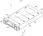
FIGS. 1 and2 are perspective views showing a battery module according to an embodiment of the present disclosure. -
FIG. 3 is a diagram showing an inner structure of the battery module depicted inFIGS. 1 and2 . -
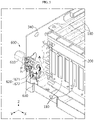
FIGS. 4 and5 are diagrams showing an inner structure of the battery module according to an embodiment of the present disclosure so that a sprinkler applied in the present disclosure is exhibited. -
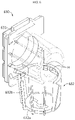
FIG. 6 is a perspective view showing an insulation cover applied in the present disclosure. -
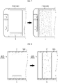
FIG. 7 is a diagram showing a part of a front surface of the battery module according to an embodiment of the present disclosure so that an expansion pad disposed inside the battery module is exhibited. -
FIGS. 8 to 10 are diagrams showing a part of a section of the battery module according to an embodiment of the present disclosure, observed from a side, so that the expansion pad disposed inside the battery module is exhibited. - Hereinafter, preferred embodiments of the present disclosure will be described in detail with reference to the accompanying drawings. Prior to the description, it should be understood that the terms used in the specification and the appended claims should not be construed as limited to general and dictionary meanings, but interpreted based on the meanings and concepts corresponding to technical aspects of the present disclosure on the basis of the principle that the inventor is allowed to define terms appropriately for the best explanation. Therefore, the description proposed herein is just a preferable example for the purpose of illustrations only, not intended to limit the scope of the disclosure, so it should be understood that other equivalents and modifications could be made thereto without departing from the scope of the disclosure.
- First, an overall structure of a
battery module 1 according to an embodiment of the present disclosure will be described with reference toFIGS. 1 to 3 . - Referring to
FIGS. 1 to 3 , thebattery module 1 according to an embodiment of the present disclosure includes a plurality ofbattery cells 100, abus bar frame 200, amodule housing 300, anair inlet 400, anair outlet 500 and asprinkler 600. - The
battery cell 100 is provided in plural, and the plurality ofbattery cells 100 are stacked to form one cell stack. Thebattery cell 100 may employ, for example, a pouch-type battery cell. Thebattery cell 100 includes a pair of electrode leads 110 respectively drawn out at both sides in a longitudinal direction (a direction parallel to the Y axis shown in the figure). Meanwhile, although not shown in the drawings, the cell stack may further include a buffer pad provided between thebattery cells 100 adjacent to each other, if necessary. When the cell stack is accommodated in themodule housing 300, the buffer pad allows the cell stack to be accommodated in a compressed state, thereby limiting movement caused by external shocks and suppressing a swelling phenomenon of thebattery cells 100. - The
bus bar frame 200 is provided in a pair, and the pair ofbus bar frames 200 cover one side and the other side of the cell stack in a width direction (a direction parallel to the Y axis in the figure). Theelectrode lead 110 of thebattery cell 100 is drawn through a slit formed at thebus bar frame 200, and is bent and fixed by welding or the like onto a bus bar provided to thebus bar frame 200. That is, the plurality ofbattery cells 100 may be electrically connected by the bus bar provided to thebus bar frame 200. - The
module housing 300 has a substantially rectangular parallelepiped shape, and accommodates the cell stack therein. Themodule housing 300 includes a pair ofbase covers 310 respectively configured to cover a lower surface and an upper surface of the cell stack (surfaces parallel to the X-Y plane), a pair ofside covers 320 respectively configured to cover side surfaces of the cell stack (surfaces parallel to the X-Z plane), afront cover 330 configured to cover a front surface of the cell stack (a surface parallel to the Y-Z plane), and arear cover 340 configured to cover a rear surface of the cell stack (a surface parallel to the Y-Z plane). - The
air inlet 400 is formed at one side of the cell stack in the stacking direction (a direction parallel to the X axis), namely at one side of thebattery module 1 in the longitudinal direction and has a hole shape formed through thefront cover 330. Theair outlet 500 is formed at the other side of the cell stack in the stacking direction, namely at the other side of thebattery module 1 in the longitudinal direction and is has a hole shape formed through therear cover 340. Theair inlet 400 and theair outlet 500 are located at diagonally opposite sides along the longitudinal direction (a direction parallel to the X axis) of thebattery module 1. - Meanwhile, an empty space is formed between the
bus bar frame 200 and theside cover 320. That is, the empty space in which air for cooling thebattery cell 100 flows is formed between one of six outer surfaces of themodule housing 300 facing one side and the other side of thebattery cell 100 in the longitudinal direction (a direction parallel to the Y axis) and thebus bar frame 200. The empty space is formed at each of both sides of thebattery module 1 in the width direction (a direction parallel to the Y axis). - The
air inlet 400 is formed at a location corresponding to the empty space formed at one side of thebattery module 1 in the width direction (a direction parallel to the Y axis), and theair outlet 500 is formed at a location corresponding to the empty space formed at the other side of thebattery module 1 in the width direction. - In the
battery module 1, the air introduced therein through theair inlet 400 cools thebattery cell 100 while moving from the empty space formed at one side of thebattery module 1 in the width direction to the empty space formed at the other side of thebattery module 1 in the width direction, and then goes out through theair outlet 500. That is, thebattery module 1 corresponds to an air-cooled battery module. - Meanwhile, in the present disclosure, the
air inlet 400 may also be used for cooling to serve as a passage through which a heated air risen is discharged, unlike its name. Also, theair outlet 500 may also be used as a passage through which an external air for cooling is introduced, unlike its name. That is, an impeller for forced ventilation may be installed at theair inlet 400 and/or theair outlet 500, and the direction of air circulation may vary depending on a rotation direction of the impeller. - The
sprinkler 600 is connected to a supply tube (not shown) that supplies a cooling fluid such as a cooling water, and thesprinkler 600 operates when the temperature inside thebattery module 1 or a flow rate of gas inside thebattery module 1 increases over a certain level, thereby supplying the cooling fluid into thebattery module 1. In other words, if an abnormal situation occurs in thebattery cell 100 to cause venting so that a high-temperature gas is discharged, thesprinkler 600 detects the high-temperature gas and operates. If thesprinkler 600 operates in this way, the cooling fluid may be supplied into thebattery module 1 to prevent thebattery cell 100 from being ignited and/or exploded due to overheating. - A part of the
sprinkler 600 is exposed out of therear cover 340, and the other part of thesprinkler 600 is provided through therear cover 340 and positioned in an empty space formed between thebus bar frame 200 and theside cover 320. Thesprinkler 600 is installed at a side opposite to theair outlet 500 that is formed on one side of therear cover 340 in a longitudinal direction (a direction parallel to the Y axis). - The
sprinkler 600 includes acoupler 610, asprinkler head 620 and aninsulation cover 630. Thecoupler 610 is positioned at an outer side of themodule housing 300 and is connected to the supply tube (not shown) that supplies the cooling fluid. That is, thecoupler 610 is made of a metal material and is a component for fastening an external supply tube. Thesprinkler head 620 is positioned at an inner side of themodule housing 300 and connected to thecoupler 610. Theinsulation cover 630 covers thesprinkler head 620, thereby preventing thesprinkler head 620 from coming into direct contact with theelectrode lead 110 of thebattery cell 100 and/or the bus bar of thebus bar frame 200 to cause a short circuit. - Referring to
FIGS. 3 to 5 , thesprinkler head 620 includes aglass bulb 621 and a holdingbracket 622. - The
glass bulb 621 blocks a cooling fluid injection hole P of thecoupler 610, and if the temperature inside thebattery module 1 or the flow rate of the internal gas heated by the venting gas increases over a reference value, theglass bulb 621 is ruptured to open the cooling fluid injection hole P. Theglass bulb 621 contains a liquid that expands as the temperature rises, and the liquid expands if venting occurs in at least some of thebattery cells 100 inside thebattery module 1 so that the high-temperature venting gas fills in thebattery module 1. As the liquid expands, the internal pressure of theglass bulb 621 increases, and at the same time, if the external force of the gas acts together due to the high-pressure venting gas at the outside of theglass bulb 621, theglass bulb 621 is ruptured, so the cooling fluid fills the inside of themodule housing 300 through the cooling fluid injection hole P. The holdingbracket 622 is made of a metal material and surrounds theglass bulb 621 to fix theglass bulb 621 not to move. - Referring to
FIGS. 5 and6 , theinsulation cover 630 includes a fixingportion 631 and acover portion 632. The fixingportion 631 is attached to therear cover 340 by clip fixing. That is, a part of the fixingportion 631 is located at an outer side of therear cover 340, and the other part of the fixingportion 631 is located at an inner side of therear cover 340. Thecover portion 632 extends in a substantially vertical direction from the fixingportion 631 and covers thesprinkler head 620. - The
cover portion 632 includes afirst region 632a facing the cell stack and thebus bar frame 200, and asecond region 632b other than the first region. Thefirst region 632a is formed so that a closed area is greater than an opened area, and thesecond region 632b is formed so that an opened area is greater than a closed area. Thecover portion 632 is at least partially opened in order to allow the cooling fluid injected through the cooling fluid injection hole P to be smoothly supplied into themodule housing 300. - In addition, the opened area of the
first region 632a is smaller than the opened area of thesecond region 632b in order to minimize the possibility of a short circuit caused by the contact between the holdingbracket 622 and theelectrode lead 110 and/or the contact between the holdingbracket 622 and the bus bar. Meanwhile, thefirst region 632a may have at least one cover hole H for injecting the cooling fluid. - Meanwhile, the
cover portion 632 is coupled to the fixingportion 631 fixed to themodule housing 300 in a detachable structure. A bonding layer A is interposed between the fixingportion 631 and thecover portion 632, so that the fixingportion 631 and thecover portion 632 are kept coupled to each other when thebattery module 1 is in a normal use state. However, if venting occurs at thebattery cell 100 to leak a high-temperature gas so that the temperature inside themodule housing 300 rises over a reference temperature, the bonding layer A melts and the bonding force of the bonding layer A is decreased or lost. Accordingly, thecover portion 632 is separated from the fixingportion 631 by injecting the cooling fluid or in advance before the cooling fluid is injected. - Other fixing elements other than the bonding layer A may not be applied to the coupling between the fixing
portion 631 and thecover portion 632, or a hinging structure may be additionally applied thereto in addition to the bonding layer A as shown in the figures. If a hinging structure is applied to couple the fixingportion 631 and thecover portion 632 to each other, thecover portion 632 is opened as rotating based on the hinged portion and as the bonding force of the bonding layer A is decreased or lost. - As the
cover portion 632 is separated from the fixingportion 631 in this way, thecover portion 632 no longer acts as an element that disturbs the injection of the cooling fluid from the cooling fluid injection hole P, thereby enabling smooth fire extinguishing and cooling. - Referring to
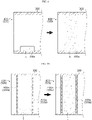
FIG. 7 , thebattery module 1 may further include an expansion pad E configured to at least partially close theair inlet 400 and theair outlet 500 so that the level of the cooling fluid rapidly increases when the cooling fluid is supplied into thebattery module 1. - The expansion pad E is attached to an inner surface of the
module housing 300 and has a size smaller than the opened area of theair inlet 400 andair outlet 500. When thebattery module 1 is in normal use, the expansion pad E preferably has a size less than about 30% of the opened area of theair inlet 400 andair outlet 500 so that air may smoothly flows through theair inlet 400 andair outlet 500. Meanwhile, even though the figures of the present disclosure just depict that the expansion pad E is attached at a bottom portion of the inner surface of themodule housing 300, the expansion pad E may also be attached to a top portion or a side portion of themodule housing 300. - The expansion pad E is expanded by contacting the cooling fluid introduced into the
battery module 1 to close theair inlet 400 and theair outlet 500. The expansion pad E contains a resin that exhibits a very large expansion rate when absorbing moisture, for example a resin that increases in volume by at least about two times or more compared to the initial volume when a sufficient amount of moisture is provided thereto. As a resin used for the expansion pad E, a non-woven fabric in which SAF (super absorbent fiber) and polyester staple fiber are mixed may be mentioned, for example. The SAF is prepared by forming a fiber using SAP (super absorbent polymer). - Meanwhile, when the
air inlet 400 and theair outlet 500 are closed due to the expansion of the expansion pad E, this does not necessarily mean that theair inlet 400 and theair outlet 500 are closed so completely that the cooling fluid cannot leak, also includes the case where the opened area of theair inlet 400 and theair outlet 500 is decreased to reduce the amount of leakage. - By applying the expansion pad E, when a thermal runaway phenomenon occurs in at least some
battery modules 1 and thus a cooling fluid is introduced into thebattery modules 1, theair inlet 400 and theair outlet 500 are closed. If theair inlet 400 and theair outlet 500 are closed as above, the cooling fluid introduced into thebattery module 1 does not escape to the outside but stays inside thebattery modules 1, thereby quickly resolving the thermal runaway phenomenon occurring in thebattery modules 1. - Referring to
FIG. 8 , the expansion pad E may be provided in a pair. In this case, the pair of expansion pads E are attached to an upper portion and a lower portion of the inner surface of themodule housing 300, respectively. The pair of expansion pads E are attached at corresponding positions and come into contact with each other to close theair inlet 400 and theair outlet 500 when being expanded. - Referring to
FIG. 9 , the expansion pad E may be fixed by inserting at least a portion of the expansion pad E into anaccommodation groove 300a formed to a predetermined depth at the inner surface of themodule housing 300. - Referring to
FIG. 10 , the expanding movement of the expansion pad E may be guided by a pair ofmesh plates mesh plates - Meanwhile, an ESS (Energy Storage System) according to an embodiment of the present disclosure includes a plurality of battery modules according to an embodiment of the present disclosure as described above.
- The present disclosure has been described in detail. However, it should be understood that the detailed description and specific examples, while indicating preferred embodiments of the disclosure, are given by way of illustration only, since various changes and modifications within the scope of the disclosure will become apparent to those skilled in the art from this detailed description.
Claims (14)
- A battery module, comprising:a plurality of battery cells;a module housing configured to accommodate a cell stack including the plurality of battery cells; anda sprinkler provided through the module housing at one side of the cell stack in a stacking direction,wherein the sprinkler includes:a coupler positioned at an outer side of the module housing and connected to a supply tube that supplies a cooling fluid;a sprinkler head positioned at an inner side of the module housing and connected to the coupler; andan insulation cover including a fixing portion fixed to the module housing and a cover portion fixed to the fixing portion by a bonding layer to cover the sprinkler head and configured to be separated from the fixing portion over a reference temperature as a bonding force of the bonding layer is decreased or lost.
- The battery module according to claim 1,
wherein the module housing includes:a pair of base covers configured to cover a lower surface and an upper surface of the cell stack, respectively;a pair of side covers configured to cover side surfaces of the cell stack;a front cover configured to cover a front surface of the cell stack; anda rear cover configured to cover a rear surface of the cell stack. - The battery module according to claim 2,
wherein the battery module comprises a pair of bus bar frames coupled to one side and the other side of the cell stack in a width direction, respectively. - The battery module according to claim 3,
wherein the sprinkler is provided through one longitudinal side of the rear cover and positioned in an empty space formed between the bus bar frame and the side cover. - The battery module according to claim 1,
wherein the sprinkler head includes:a glass bulb provided to block a cooling fluid injection hole of the coupler and configured to be ruptured to open the cooling fluid injection hole when temperature or a flow rate of gas inside the battery module increases over a reference value; anda holding bracket configured to fix the glass bulb while surrounding the glass bulb. - The battery module according to claim 1,wherein the insulation cover includes a first region facing the cell stack and the bus bar frame and a second region other than the first region, andthe first region is formed such that a closed area is greater than an opened area, and the second region is formed such that an opened area is greater than a closed area.
- The battery module according to claim 6,
wherein the first region has at least one cover hole for injecting the cooling fluid. - The battery module according to claim 3,
wherein the battery module comprises:an air inlet formed through the front cover;an air outlet formed through the rear cover; andan expansion pad disposed at an inner side of the air inlet and the air outlet and configured to at least partially close the air inlet and the air outlet by expanding when contacting the cooling fluid introduced into the battery module. - The battery module according to claim 8,
wherein the expansion pad is attached onto an inner surface of the module housing. - The battery module according to claim 8,
wherein the expansion pad is at least partially inserted into an accommodation groove formed at an inner surface of the module housing. - The battery module according to claim 8,
wherein the battery module comprises mesh plates respectively disposed at both sides of the expansion pad to guide an expanding movement of the expansion pad. - The battery module according to claim 8,
wherein the air inlet and the air outlet are formed at locations corresponding to an empty space formed between the bus bar frame and the side cover. - The battery module according to claim 1,
wherein the cover portion is hinged to the fixing portion and is opened by rotating downward based of the sprinkler head on the hinged portion over the reference temperature. - An ESS, comprising a plurality of battery modules according to any one of claims 1 to 13.
Applications Claiming Priority (2)
| Application Number | Priority Date | Filing Date | Title |
|---|---|---|---|
| KR1020200024459A KR102858181B1 (en) | 2020-02-27 | 2020-02-27 | Battery module having a structure capable of rapid cooling and the Energy Storage System comprising the same |
| PCT/KR2021/000630 WO2021172757A1 (en) | 2020-02-27 | 2021-01-15 | Battery module having structure capable of rapid cooling, and ess comprising same |
Publications (2)
| Publication Number | Publication Date |
|---|---|
| EP4024566A1 true EP4024566A1 (en) | 2022-07-06 |
| EP4024566A4 EP4024566A4 (en) | 2023-12-06 |
Family
ID=77491226
Family Applications (1)
| Application Number | Title | Priority Date | Filing Date |
|---|---|---|---|
| EP21760150.9A Pending EP4024566A4 (en) | 2020-02-27 | 2021-01-15 | Battery module having structure capable of rapid cooling, and ess comprising same |
Country Status (6)
| Country | Link |
|---|---|
| US (1) | US12512533B2 (en) |
| EP (1) | EP4024566A4 (en) |
| JP (1) | JP7345628B2 (en) |
| KR (1) | KR102858181B1 (en) |
| CN (1) | CN114365326B (en) |
| WO (1) | WO2021172757A1 (en) |
Family Cites Families (25)
| Publication number | Priority date | Publication date | Assignee | Title |
|---|---|---|---|---|
| JPH0531207A (en) * | 1991-08-01 | 1993-02-09 | Ngk Insulators Ltd | Fire extinguisher in sodium-sulfur battery |
| GB0020551D0 (en) * | 2000-08-22 | 2000-10-11 | Birkett David | Sprinkler system |
| KR200394311Y1 (en) * | 2005-06-01 | 2005-08-31 | 대명기계공업 주식회사 | Sprinkler head |
| FI122096B (en) * | 2006-01-18 | 2011-08-31 | Marioff Corp Oy | Sprinkler |
| US9114267B2 (en) * | 2009-03-17 | 2015-08-25 | The Viking Corporation | Concealed residential sprinkler |
| JP5618641B2 (en) * | 2010-06-07 | 2014-11-05 | 能美防災株式会社 | Fire extinguisher |
| US20170043194A1 (en) * | 2012-04-10 | 2017-02-16 | Greg Ling | Integrated thermal event suppression system |
| JP6103856B2 (en) * | 2012-08-20 | 2017-03-29 | ホーチキ株式会社 | Fire extinguishing system for electric vehicles |
| JP6103887B2 (en) * | 2012-11-01 | 2017-03-29 | ホーチキ株式会社 | Power storage system |
| JP2015153616A (en) * | 2014-02-14 | 2015-08-24 | 株式会社オートネットワーク技術研究所 | Battery pack |
| JP2015230756A (en) | 2014-06-03 | 2015-12-21 | 三菱自動車工業株式会社 | Secondary battery |
| JP2016002419A (en) | 2014-06-19 | 2016-01-12 | Necエンジニアリング株式会社 | Fire-extinguishing system and fire-extinguishing method for power storage device |
| EP3352243A4 (en) * | 2015-12-09 | 2018-10-17 | LG Chem, Ltd. | Battery pack and vehicle having the battery pack |
| JP2019075191A (en) | 2016-03-08 | 2019-05-16 | パナソニックIpマネジメント株式会社 | Power storage device |
| KR101647427B1 (en) * | 2016-05-18 | 2016-08-11 | 주식회사 풍성인더스 | DC power breaker, and solar power generating system having the same |
| KR102102927B1 (en) * | 2016-10-06 | 2020-04-21 | 주식회사 엘지화학 | Battery module, battery pack comprising the battery module and vehicle comprising the battery pack |
| CN206388817U (en) | 2016-12-02 | 2017-08-08 | 重庆壹特科技有限公司 | A kind of battery anti-explosion flame retardant systems |
| CN106684499A (en) | 2017-01-09 | 2017-05-17 | 武汉船用电力推进装置研究所(中国船舶重工集团公司第七二研究所) | Method and apparatus for suppressing and preventing thermal runway of lithium ion battery |
| US11186970B2 (en) * | 2017-03-29 | 2021-11-30 | Aquor Water Systems, Incorporated | Anti-freezing water valve configured for underground (buried) use and with optional anti-siphon assembly, and water-valve accessories |
| JP2019092790A (en) * | 2017-11-22 | 2019-06-20 | ヤマトプロテック株式会社 | Head for fire extinction |
| JP7022481B2 (en) | 2017-11-22 | 2022-02-18 | 株式会社大一商会 | Pachinko machine |
| KR102150679B1 (en) * | 2018-03-13 | 2020-09-01 | 주식회사 엘지화학 | Battery module, battery pack comprising the battery module and vehicle comprising the battery pack |
| KR102142993B1 (en) | 2018-08-28 | 2020-08-28 | 대우조선해양 주식회사 | Insulation System of Liquefied Gas Storage Tank |
| KR102021072B1 (en) | 2019-05-15 | 2019-11-05 | 주식회사 아산정밀 | Fire protection system for energy storage system |
| EP3968442B1 (en) * | 2019-11-08 | 2025-01-01 | LG Energy Solution, Ltd. | Battery module, battery rack comprising same, and power storage device |
-
2020
- 2020-02-27 KR KR1020200024459A patent/KR102858181B1/en active Active
-
2021
- 2021-01-15 US US17/625,984 patent/US12512533B2/en active Active
- 2021-01-15 JP JP2022505494A patent/JP7345628B2/en active Active
- 2021-01-15 EP EP21760150.9A patent/EP4024566A4/en active Pending
- 2021-01-15 WO PCT/KR2021/000630 patent/WO2021172757A1/en not_active Ceased
- 2021-01-15 CN CN202180005135.5A patent/CN114365326B/en active Active
Also Published As
| Publication number | Publication date |
|---|---|
| EP4024566A4 (en) | 2023-12-06 |
| JP2022544040A (en) | 2022-10-17 |
| US12512533B2 (en) | 2025-12-30 |
| KR102858181B1 (en) | 2025-09-10 |
| CN114365326A (en) | 2022-04-15 |
| US20220278392A1 (en) | 2022-09-01 |
| CN114365326B (en) | 2024-08-02 |
| JP7345628B2 (en) | 2023-09-15 |
| KR20210109712A (en) | 2021-09-07 |
| WO2021172757A1 (en) | 2021-09-02 |
Similar Documents
| Publication | Publication Date | Title |
|---|---|---|
| US12362408B2 (en) | Battery module having structure capable of rapid cooling, and ESS comprising same | |
| EP3993140B1 (en) | Battery module having structure capable of rapid cooling, and ess comprising same | |
| EP4044324B1 (en) | Battery module having structure capable of rapid cooling, and ess comprising same | |
| US12334529B2 (en) | Battery module having structure enabling rapid deployment of sprinkler, and ESS including same | |
| US12512533B2 (en) | Battery module having structure capable of rapid cooling, and ESS comprising same |
Legal Events
| Date | Code | Title | Description |
|---|---|---|---|
| STAA | Information on the status of an ep patent application or granted ep patent |
Free format text: STATUS: THE INTERNATIONAL PUBLICATION HAS BEEN MADE |
|
| PUAI | Public reference made under article 153(3) epc to a published international application that has entered the european phase |
Free format text: ORIGINAL CODE: 0009012 |
|
| STAA | Information on the status of an ep patent application or granted ep patent |
Free format text: STATUS: REQUEST FOR EXAMINATION WAS MADE |
|
| 17P | Request for examination filed |
Effective date: 20220330 |
|
| AK | Designated contracting states |
Kind code of ref document: A1 Designated state(s): AL AT BE BG CH CY CZ DE DK EE ES FI FR GB GR HR HU IE IS IT LI LT LU LV MC MK MT NL NO PL PT RO RS SE SI SK SM TR |
|
| DAV | Request for validation of the european patent (deleted) | ||
| DAX | Request for extension of the european patent (deleted) | ||
| A4 | Supplementary search report drawn up and despatched |
Effective date: 20231108 |
|
| RIC1 | Information provided on ipc code assigned before grant |
Ipc: A62C 35/68 20060101ALI20231102BHEP Ipc: A62C 35/60 20060101ALI20231102BHEP Ipc: A62C 2/06 20060101ALI20231102BHEP Ipc: A62C 37/14 20060101ALI20231102BHEP Ipc: A62C 3/16 20060101ALI20231102BHEP Ipc: H01M 50/502 20210101ALI20231102BHEP Ipc: H01M 50/20 20210101ALI20231102BHEP Ipc: H01M 50/24 20210101ALI20231102BHEP Ipc: H01M 10/613 20140101ALI20231102BHEP Ipc: H01M 10/6567 20140101ALI20231102BHEP Ipc: H01M 10/627 20140101AFI20231102BHEP |
|
| GRAP | Despatch of communication of intention to grant a patent |
Free format text: ORIGINAL CODE: EPIDOSNIGR1 |
|
| STAA | Information on the status of an ep patent application or granted ep patent |
Free format text: STATUS: GRANT OF PATENT IS INTENDED |
|
| INTG | Intention to grant announced |
Effective date: 20260120 |
|
| P01 | Opt-out of the competence of the unified patent court (upc) registered |
Free format text: CASE NUMBER: UPC_APP_0003924_4024566/2026 Effective date: 20260203 |