EP4024417A1 - Push-pull solenoid - Google Patents
Push-pull solenoid Download PDFInfo
- Publication number
- EP4024417A1 EP4024417A1 EP19943501.7A EP19943501A EP4024417A1 EP 4024417 A1 EP4024417 A1 EP 4024417A1 EP 19943501 A EP19943501 A EP 19943501A EP 4024417 A1 EP4024417 A1 EP 4024417A1
- Authority
- EP
- European Patent Office
- Prior art keywords
- plunger
- case
- friction
- push
- axial direction
- Prior art date
- Legal status (The legal status is an assumption and is not a legal conclusion. Google has not performed a legal analysis and makes no representation as to the accuracy of the status listed.)
- Pending
Links
Images


Classifications
-
- H—ELECTRICITY
- H01—ELECTRIC ELEMENTS
- H01F—MAGNETS; INDUCTANCES; TRANSFORMERS; SELECTION OF MATERIALS FOR THEIR MAGNETIC PROPERTIES
- H01F7/00—Magnets
- H01F7/06—Electromagnets; Actuators including electromagnets
- H01F7/08—Electromagnets; Actuators including electromagnets with armatures
- H01F7/13—Electromagnets; Actuators including electromagnets with armatures characterised by pulling-force characteristics
-
- H—ELECTRICITY
- H01—ELECTRIC ELEMENTS
- H01F—MAGNETS; INDUCTANCES; TRANSFORMERS; SELECTION OF MATERIALS FOR THEIR MAGNETIC PROPERTIES
- H01F7/00—Magnets
- H01F7/06—Electromagnets; Actuators including electromagnets
- H01F7/08—Electromagnets; Actuators including electromagnets with armatures
- H01F7/081—Magnetic constructions
-
- F—MECHANICAL ENGINEERING; LIGHTING; HEATING; WEAPONS; BLASTING
- F16—ENGINEERING ELEMENTS AND UNITS; GENERAL MEASURES FOR PRODUCING AND MAINTAINING EFFECTIVE FUNCTIONING OF MACHINES OR INSTALLATIONS; THERMAL INSULATION IN GENERAL
- F16K—VALVES; TAPS; COCKS; ACTUATING-FLOATS; DEVICES FOR VENTING OR AERATING
- F16K31/00—Actuating devices; Operating means; Releasing devices
- F16K31/02—Actuating devices; Operating means; Releasing devices electric; magnetic
-
- H—ELECTRICITY
- H01—ELECTRIC ELEMENTS
- H01F—MAGNETS; INDUCTANCES; TRANSFORMERS; SELECTION OF MATERIALS FOR THEIR MAGNETIC PROPERTIES
- H01F7/00—Magnets
- H01F7/06—Electromagnets; Actuators including electromagnets
- H01F7/08—Electromagnets; Actuators including electromagnets with armatures
- H01F7/121—Guiding or setting position of armatures, e.g. retaining armatures in their end position
-
- H—ELECTRICITY
- H01—ELECTRIC ELEMENTS
- H01F—MAGNETS; INDUCTANCES; TRANSFORMERS; SELECTION OF MATERIALS FOR THEIR MAGNETIC PROPERTIES
- H01F7/00—Magnets
- H01F7/06—Electromagnets; Actuators including electromagnets
- H01F7/08—Electromagnets; Actuators including electromagnets with armatures
- H01F7/16—Rectilinearly-movable armatures
-
- H—ELECTRICITY
- H01—ELECTRIC ELEMENTS
- H01F—MAGNETS; INDUCTANCES; TRANSFORMERS; SELECTION OF MATERIALS FOR THEIR MAGNETIC PROPERTIES
- H01F7/00—Magnets
- H01F7/06—Electromagnets; Actuators including electromagnets
- H01F7/08—Electromagnets; Actuators including electromagnets with armatures
- H01F7/16—Rectilinearly-movable armatures
- H01F7/1607—Armatures entering the winding
- H01F7/1623—Armatures having T-form
-
- H—ELECTRICITY
- H01—ELECTRIC ELEMENTS
- H01F—MAGNETS; INDUCTANCES; TRANSFORMERS; SELECTION OF MATERIALS FOR THEIR MAGNETIC PROPERTIES
- H01F7/00—Magnets
- H01F7/06—Electromagnets; Actuators including electromagnets
- H01F7/08—Electromagnets; Actuators including electromagnets with armatures
- H01F7/081—Magnetic constructions
- H01F2007/086—Structural details of the armature
Definitions
- the present invention relates to a push-pull solenoid, and more specifically relates to a push-pull solenoid that is not provided with a recovery mechanism such as a recovery spring that applies force in a direction opposite from an attraction direction to a plunger and returns the plunger to an original position.
- a recovery mechanism such as a recovery spring that applies force in a direction opposite from an attraction direction to a plunger and returns the plunger to an original position.
- Push-pull solenoids are disclosed in, e.g., Patent Documents 1 and 2.
- a plunger that is located at an initial position (return position) set apart from one end surface of a case is attracted by magnetic force toward a fixed iron core arranged inside the case and is withdrawn to a withdrawn position.
- a shaft that is coaxially linked to the plunger is pushed out from a case end surface on the opposite side. What is performed is, e.g., a manipulation in which an article to be manipulated is pushed out by the shaft.
- the plunger which has slid to the withdrawn position, returns to a free state in which the plunger is allowed to slide freely at that position because no recovery spring or other recovery mechanism is provided.
- Push-pull solenoids provided with a recovery spring as a mechanism for recovering the plunger are also known in the prior art.
- a compression coil spring is arranged as the recovery spring between a case end surface and the distal end of a plunger protruding from the case end surface.
- the two ends of the recovery spring are not respectively linked to the plunger and the case, it will be impossible to precisely position the plunger at a return position or an attraction position, and adverse events such as shock-like contact with an object and a reduction in attraction will occur.
- the recovery spring when the recovery spring is mounted, the axial length of the solenoid will increase by a corresponding amount, and the stroke of the plunger will become shorter by an amount corresponding to the close-contact length of the recovery spring.
- the plunger slides along the friction guide surface of the guide member when sliding in the axial direction.
- Prescribed friction acts on the plunger sliding along the friction guide surface in a direction opposite from the sliding direction.
- a cylindrical member that coaxially surrounds the plunger protruding from the case end surface can be used as the guide member.
- An outer peripheral surf ace that slides in the axial direction along the inner peripheral surface of the cylindrical member is preferably formed on the plunger. Due to a simple configuration in which the cylindrical member is fixed to the end of the case, it is possible to ensure stable operation of the plunger in a push-pull solenoid that is not provided with a plunger recovery mechanism.
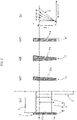
- FIGS. 1(a) and 1(b) are explanatory diagrams showing the main configuration of a push-pull solenoid to which the present invention is applied;
- FIGS. 1(a) and 1(b) are explanatory diagrams showing the main configuration of the push-pull solenoid according to this embodiment; these drawings show the right half in cross-section.
- the push-pull solenoid 1 (also referred to as the "solenoid 1" below) is provided with a case 2 formed from a magnetic material, a base 3 that is a fixed iron core formed from a magnetic material, a plunger 4 that is a movable iron core formed from a magnetic material, and a coil 5.
- a shaft 6 formed from a non-magnetic material is securely linked to the plunger 4 in a coaxial manner.
- the plunger 4 faces the base 3 in an axial direction 1a.
- the coil 5 is fixed to an inner peripheral surface of the case 2 and coaxially surrounds the facing portions of the base 3 and the plunger 4.
- magnetic attraction is generated between the base 3 and the plunger 4 facing each other in the axial direction 1a. Due to the magnetic attraction, the plunger 4 is attracted from an initial position (return position) 4A shown in FIG. 1(a) , at which the plunger 4 protrudes from one case end surface 21 of the case 2, to a withdrawn position 4B shown in FIG. 1(b) , at which the plunger 4 is withdrawn toward the case end surface 21.
- one shaft end section 61 protrudes in the axial direction 1a from the distal end surface of the plunger 4.
- the shaft 6 extends through a central shaft hole 31 in the base 3 in a slidable state.
- Another shaft end section 62 of the shaft 6 passes through the central shaft hole 31 in the base 3 and protrudes outward from another case end surface 22 of the case 2.
- the shaft 6 In a state in which the plunger 4 is located at the initial position (return position) 4A, the shaft 6 is located at a retreat position 6A, at which the shaft end section 62 is withdrawn toward the case end surface 22.
- the shaft 6 When the plunger 4 is attracted to the withdrawn position 4B, the shaft 6 also slides in the same direction, sliding to a push-out position 6B, at which the shaft end section 62 is pushed out from the case end surface 22.
- an article to be manipulated W which is in contact with a shaft manipulation end 63 that is the distal end of the shaft end section 62, is pushed in the axial direction 1a by a prescribed distance due to the push-out operation of the shaft 6.
- the article to be manipulated W in the present example is provided with prescribed spring stiffness in the axial direction 1a.
- the plunger 4 protruding from the case end surface 21 of the case 2 is provided with a small-diameter cylinder section 41 extending through a circular opening 23 in the case end surface 21 in a state in which sliding is allowed, and a large-diameter disc-form plunger head section 42 that protrudes outside of the case and that is formed at the distal end of the cylinder section 41.
- the outer peripheral surface of the plunger head section 42 is configured as a circular outer peripheral surface 43 of uniform width.
- a guide member 7 that guides the sliding of the plunger 4 is attached to the case-end-surface 21 side of the case 2.
- the guide member 7 in the present example is a cylinder member formed from a non-magnetic material.
- the guide member 7 coaxially surrounds the portion of the plunger 4 that protrudes from the case end surface 21.
- One end of the circular inner peripheral surface of the guide member 7 is configured as a case-side fixed section 71 that is coaxially fixed by bonding to the outer peripheral surface of the case 2.
- the remaining inner peripheral surface portion of the circular inner peripheral surface is configured as a friction guide surface 72 that guides the circular outer peripheral surface 43 of the plunger 4 in the axial direction 1a in association with prescribed friction.
- the guide member 7 is preferably formed from a gel material, an elastomer material, or a plastic material so that it is possible to generate small friction suited to the application.
- FIGS. 2(a) and 2(b) are graphs showing the relationship between a slide position (stroke) of the plunger 4 and force acting on the plunger 4 when the solenoid 1 is on and when the solenoid 1 is off.
- the plunger 4 is located at the initial position (return position) 4A at which the plunger 4 protrudes from the case end surface 21.
- the shaft manipulation end 63 of the shaft 6 comes into contact with the article to be manipulated W, which is provided with spring stiffness, from the axial direction 1a.
- the plunger 4 When the solenoid 1 is turned on and the coil 5 is energized, the plunger 4 is attracted by magnetic force toward the base 3, the plunger 4 being attracted from the initial position (return position) 4A to the withdrawn position 4B.
- the shaft 6 in contact with the article to be manipulated W is thereby pushed out from the retreat position 6A to the push-out position 6B, pushing out the article to be manipulated W.
- the circular outer peripheral surface 43 of the plunger head section 42 slides in the axial direction 1a in association with uniform frictional resistive force along the friction guide surface 72 formed on the circular inner peripheral surface of the guide member 7 attached to the case 2.
- curve A indicates the magnitude of magnetic force produced between the base 3 and the plunger 4.
- the magnetic force increases as the plunger 4 approaches the base 3.
- straight line B1 indicates friction produced between the plunger 4 and the guide member 7.
- the friction has a uniform magnitude irrespective of the slide position of the plunger 4 and acts in a return direction opposite from the plunger attraction direction.
- the solenoid 1 is turned off and the energization of the coil 5 is stopped.
- the plunger 4 is released, and due to the external force from the article to be manipulated W that is acting on the shaft 6, the plunger 4 is pushed back from the withdrawn position 4B toward the initial position (return position) 4A.
- the friction produced between the plunger 4 and the guide member 7 has a uniform value and acts in the plunger attraction direction, as indicated by straight line B2.
- the external force decreases as the plunger 4 approaches the return position, as indicated by straight line C.
- the plunger 4 can be stopped at the initial position (return position). This makes it possible to prevent over-recovery, in which the plunger 4 is pushed back to a position beyond the initial position (return position) by the external force. It is also possible to prevent dislodgment, in which the plunger 4 slips out from the case 2. Furthermore, because the plunger 4 can be precisely recovered to the initial position (return position), it is possible, during the subsequent energization, to attract the plunger 4 toward the withdrawn position using suitable attraction.
- the guide member 7 in the present example is a cylinder member of uniform thickness, and the inside-diameter dimensions of the circular inner peripheral surface thereof are uniform at each position in the axial direction 1a.
- the friction produced at each slide position of the plunger 4 is thereby uniform.
- the inside diameter, thickness, and degree of interference of the guide member 7, which is formed in a cylinder shape, are preferably designed so that the required friction is obtained. In particular, the friction changes greatly according to the axial-direction cross-section of the guide member 7 having the cylinder shape.
- FIGS. 3(a1) to 3(a4) show examples of guide members for which the axial-direction cross-sectional shape is configured in four different types of cylinder shapes.
- FIG. 3(b) is a graph showing the relationship between friction and the slide position of the plunger 4 in cases where guide members having each of the shapes are used.
- Straight line C in FIG. 3(b) shows reaction force from outside, similarly to the case shown in FIG. 2 .
- a guide member 17 having the cylinder shape shown in FIG. 3(a1) is the same as the guide member 7 shown in FIG. 1 .
- the guide member 17 has a cross-sectional shape in which the thickness is the same in the axial direction, and the inside diameter of a friction guide surface 17a is also the same. In this instance, as indicated by a line a1 in FIG. 3(b) , the friction acting on the plunger 4 is substantially uniform.
- a guide member 37 having the cylinder shape shown in FIG. 3(a3) has a cross-sectional shape such that the outside diameter and the inside diameter both gradually decrease along the axial direction from the position 7A to the position 7B.
- Friction produced by a friction guide surface 37a increases linearly with a high slope along the axial direction from the position 7A to the position 7B, as indicated by a line a3 in FIG. 3(b) .
- a guide member 47 having the cylinder shape shown in FIG. 3(a4) has a cross-sectional shape such that the outside diameter is uniform and the inside diameter gradually decreases in a curving manner along the axial direction from the position 7A to the position 7B. Friction of a curved-surface friction guide surface 47a in this instance increases in a curving manner along the axial direction from the position 7A to the position 7B, as indicated by a line a4 in FIG. 3(b) .
- changing the cross-sectional shape of the cylinder member makes it possible to obtain required friction.
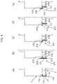
- FIG. 4 is a set of explanatory diagrams showing further examples of guide members having cylinder shapes.
- a guide member 170 shown in FIG. 4(a) is provided with a cylinder portion 171 provided with a friction guide surface 175 formed from a circular inner peripheral surface, and an annular flange 172 formed so as to be bent radially inward at a right angle from one open end of the cylinder portion 171.
- An annular end surface 173 of the annular flange 172 is a case-side fixed section that is fixed by bonding to the case end surface of the case 2.
- annular flange 273 that protrudes radially inward is formed integrally with a cylinder body 271 at a position near one axial-direction open end 272 in the circular inner peripheral surface of the cylinder body 271.
- a circular inner peripheral surface extending from another open end 274 of the cylinder body 271 to the annular flange 273 is a friction guide surface 275.
- the annular flange 273 is positioned between the plunger 4 and the case 2 in the axial direction and functions as an air gap spacer for reducing effects of residual magnetism when the plunger 4 is recovered to the initial position (return position).
- the annular end surface of the annular flange 273 facing toward the case 2 and the circular inner peripheral surface of the cylinder body are case-side fixed sections 276 that are fixed by bonding to the case.
- a guide member 370 shown in FIG. 4(c) is configured such that a large-diameter cylinder body 372 is formed coaxially and integrally with a small-diameter cylinder body 371.
- the circular inner peripheral surface of the small-diameter cylinder body 371 is a friction guide surface 373.
- the circular inner peripheral surface of the large-diameter cylinder body 372 and the annular end surface of the cylinder body are case-side fixed sections 374 that are fixed by bonding to the case.
- a guide member 470 shown in FIG. 4(d) is configured such that an annular flange 472 is formed coaxially and integrally with the end of a cylinder body 471.
- the circular inner peripheral surface of the cylinder body 471 is a friction guide surface 473.
- the annular flange 472 extends radially inward and outward from the cylinder body 471.
- the annular end surface of the annular flange 472 is a case-side fixed section 474 that is fixed by bonding to the case end surface of the case.
- a guide member 570 shown in FIG. 4(e) is provided with a small-diameter cylinder body 571, a large-diameter cylinder body 572 that is formed coaxially and integrally with the end of the small-diameter cylinder body 571, and an annular flange 573 formed between the two cylinder bodies.
- the circular inner peripheral surface of the small-diameter cylinder body 571 is a friction guide surface 574.
- the annular flange 573 protrudes further radially inward than the circular inner peripheral surface of the small-diameter cylinder body 571 and functions as an air gap spacer.
- the circular inner peripheral surface of the large-diameter cylinder body 572 and the annular end surface of the annular flange 573 are case-side fixed sections 575 that are fixed by bonding to the case 2.
Landscapes
- Physics & Mathematics (AREA)
- Electromagnetism (AREA)
- Engineering & Computer Science (AREA)
- Power Engineering (AREA)
- General Engineering & Computer Science (AREA)
- Mechanical Engineering (AREA)
- Electromagnets (AREA)
Abstract
Description
- The present invention relates to a push-pull solenoid, and more specifically relates to a push-pull solenoid that is not provided with a recovery mechanism such as a recovery spring that applies force in a direction opposite from an attraction direction to a plunger and returns the plunger to an original position.
- Push-pull solenoids are disclosed in, e.g.,
Patent Documents - In cases where the article to be manipulated is, inter alia, a component having spring stiffness, an acceleration load will be applied, in a direction in which the shaft is pushed back, from the article to be manipulated to the shaft in the free state, and the shaft and the plunger will be pushed back toward the initial position (return position). In this instance, there are cases where the plunger is pushed back excessively to a position beyond the original initial position (return position) by inertia (over-recovery). In addition, in cases where the plunger is held in an orientation in which gravitational force is applied in the axial direction, because the weight of the shaft and the plunger is applied to the inertia produced by the load applied from the article to be manipulated, there is a concern that the shaft and the plunger will be dislodged from the case.
- When the plunger is pushed back beyond the initial position (return position) and has been moved away from the fixed iron core by a set distance or greater, adverse events will occur, such as those in which, when the coil is again energized and the plunger is attracted, the attraction decreases or is not generated, the stroke of the plunger caused by the attraction increases, and the plunger makes shock-like contact with the article to be manipulated. As a result, it will be difficult to perform the manipulation in a consistently repetitive manner.
- Push-pull solenoids provided with a recovery spring as a mechanism for recovering the plunger are also known in the prior art. For example, a compression coil spring is arranged as the recovery spring between a case end surface and the distal end of a plunger protruding from the case end surface. In this instance, if the two ends of the recovery spring are not respectively linked to the plunger and the case, it will be impossible to precisely position the plunger at a return position or an attraction position, and adverse events such as shock-like contact with an object and a reduction in attraction will occur. In addition, when the recovery spring is mounted, the axial length of the solenoid will increase by a corresponding amount, and the stroke of the plunger will become shorter by an amount corresponding to the close-contact length of the recovery spring.
-
- Patent Document 1:
JPU H02-98607 A - Patent Document 2:
JP S63-273306 A - In view of the foregoing, it is an object of the present invention to provide a push-pull solenoid provided with a simple mechanism with which it is possible to suppress shock-like contact with an article to be manipulated during attraction of a plunger, as well as vibration and noise caused by said contact, and with which it is possible to prevent the plunger from excessive recovery or dislodgment after the attraction is released.
- The push-pull solenoid of the present invention is characterized by being provided with
- a case,
- a base that is formed from a magnetic material, the base being fixed to the case,
- a plunger that is formed from a magnetic material, the plunger protruding from one axial-direction case end surface of the case in a state in which sliding in the axial direction is allowed,
- a coil that generates magnetic attraction for causing the plunger to slide in the axial direction from a return position set apart from the case end surface in a withdrawing direction approaching the case end surface, and
- a guide member that is attached to the case,
- the guide member being provided with a friction guide surface that guides the plunger in the axial direction in association with prescribed friction.
- In the push-pull solenoid of the present invention, the plunger slides along the friction guide surface of the guide member when sliding in the axial direction. Prescribed friction acts on the plunger sliding along the friction guide surface in a direction opposite from the sliding direction. Once the attraction is released by turning off the energization, the plunger will not assume a free state in which sliding in the axial direction is allowed, and axial-direction sliding of the plunger will be restricted by the friction. Setting the friction to a suitable magnitude makes it possible to prevent over-recovery of the plunger caused by externally applied force, as well as to prevent the plunger from being dislodged the case, and also makes it possible to prevent or reduce shock-like contact with an article to be manipulated during attraction of the plunger, as well as vibration and noise caused by said contact.
- A cylindrical member that coaxially surrounds the plunger protruding from the case end surface can be used as the guide member. In this instance, it is preferable to use the inner peripheral surface of the cylindrical member as the friction guide surface. An outer peripheral surf ace that slides in the axial direction along the inner peripheral surface of the cylindrical member is preferably formed on the plunger. Due to a simple configuration in which the cylindrical member is fixed to the end of the case, it is possible to ensure stable operation of the plunger in a push-pull solenoid that is not provided with a plunger recovery mechanism.
-
FIGS. 1(a) and 1(b) are explanatory diagrams showing the main configuration of a push-pull solenoid to which the present invention is applied; -
FIGS. 2(a) and 2(b) are graphs showing the relationship between a slide position of a plunger and force acting on the plunger; -
FIGS. 3(a1) to 3(a4) are explanatory diagrams showing guide members for which the axial-direction cross-sectional shape is configured in four different types of cylinder shapes, andFIG. 3(b) is a graph showing the relationship between friction and the slide position of the plunger in cases where guide members having each of the shapes are used; and -
FIGS. 4(a) to 4(e) are explanatory diagrams showing examples of guide members having cylinder shapes. - An embodiment of a push-pull solenoid to which the present invention is applied is described below with reference to the drawings.
FIGS. 1(a) and 1(b) are explanatory diagrams showing the main configuration of the push-pull solenoid according to this embodiment; these drawings show the right half in cross-section. The push-pull solenoid 1 (also referred to as the "solenoid 1" below) is provided with acase 2 formed from a magnetic material, abase 3 that is a fixed iron core formed from a magnetic material, aplunger 4 that is a movable iron core formed from a magnetic material, and acoil 5. Ashaft 6 formed from a non-magnetic material is securely linked to theplunger 4 in a coaxial manner. - Inside the
case 2, theplunger 4 faces thebase 3 in anaxial direction 1a. Thecoil 5 is fixed to an inner peripheral surface of thecase 2 and coaxially surrounds the facing portions of thebase 3 and theplunger 4. When thecoil 5 is energized, magnetic attraction is generated between thebase 3 and theplunger 4 facing each other in theaxial direction 1a. Due to the magnetic attraction, theplunger 4 is attracted from an initial position (return position) 4A shown inFIG. 1(a) , at which theplunger 4 protrudes from onecase end surface 21 of thecase 2, to a withdrawnposition 4B shown inFIG. 1(b) , at which theplunger 4 is withdrawn toward thecase end surface 21. - In the
shaft 6, which slides integrally with theplunger 4, oneshaft end section 61 protrudes in theaxial direction 1a from the distal end surface of theplunger 4. Theshaft 6 extends through acentral shaft hole 31 in thebase 3 in a slidable state. Anothershaft end section 62 of theshaft 6 passes through thecentral shaft hole 31 in thebase 3 and protrudes outward from anothercase end surface 22 of thecase 2. - In a state in which the
plunger 4 is located at the initial position (return position) 4A, theshaft 6 is located at aretreat position 6A, at which theshaft end section 62 is withdrawn toward thecase end surface 22. When theplunger 4 is attracted to the withdrawnposition 4B, theshaft 6 also slides in the same direction, sliding to a push-outposition 6B, at which theshaft end section 62 is pushed out from thecase end surface 22. For example, an article to be manipulated W, which is in contact with ashaft manipulation end 63 that is the distal end of theshaft end section 62, is pushed in theaxial direction 1a by a prescribed distance due to the push-out operation of theshaft 6. The article to be manipulated W in the present example is provided with prescribed spring stiffness in theaxial direction 1a. - The
plunger 4 protruding from thecase end surface 21 of thecase 2 is provided with a small-diameter cylinder section 41 extending through acircular opening 23 in thecase end surface 21 in a state in which sliding is allowed, and a large-diameter disc-formplunger head section 42 that protrudes outside of the case and that is formed at the distal end of thecylinder section 41. The outer peripheral surface of theplunger head section 42 is configured as a circular outerperipheral surface 43 of uniform width. - A
guide member 7 that guides the sliding of theplunger 4 is attached to the case-end-surface 21 side of thecase 2. Theguide member 7 in the present example is a cylinder member formed from a non-magnetic material. Theguide member 7 coaxially surrounds the portion of theplunger 4 that protrudes from thecase end surface 21. One end of the circular inner peripheral surface of theguide member 7 is configured as a case-side fixedsection 71 that is coaxially fixed by bonding to the outer peripheral surface of thecase 2. The remaining inner peripheral surface portion of the circular inner peripheral surface is configured as afriction guide surface 72 that guides the circular outerperipheral surface 43 of theplunger 4 in theaxial direction 1a in association with prescribed friction. Theguide member 7 is preferably formed from a gel material, an elastomer material, or a plastic material so that it is possible to generate small friction suited to the application. - An operating example of a case in which the article to be manipulated W is pushed out by the
solenoid 1 is described below with reference toFIGS. 1 and2. FIGS. 2(a) and 2(b) are graphs showing the relationship between a slide position (stroke) of theplunger 4 and force acting on theplunger 4 when thesolenoid 1 is on and when thesolenoid 1 is off. - In the
solenoid 1, as shown inFIG. 1(a) , theplunger 4 is located at the initial position (return position) 4A at which theplunger 4 protrudes from the case endsurface 21. Theshaft manipulation end 63 of theshaft 6 comes into contact with the article to be manipulated W, which is provided with spring stiffness, from theaxial direction 1a. - When the
solenoid 1 is turned on and thecoil 5 is energized, theplunger 4 is attracted by magnetic force toward thebase 3, theplunger 4 being attracted from the initial position (return position) 4A to the withdrawnposition 4B. Theshaft 6 in contact with the article to be manipulated W is thereby pushed out from theretreat position 6A to the push-outposition 6B, pushing out the article to be manipulated W. The circular outerperipheral surface 43 of theplunger head section 42 slides in theaxial direction 1a in association with uniform frictional resistive force along thefriction guide surface 72 formed on the circular inner peripheral surface of theguide member 7 attached to thecase 2. - In
FIG. 2(a) , curve A indicates the magnitude of magnetic force produced between thebase 3 and theplunger 4. The magnetic force increases as theplunger 4 approaches thebase 3. In contrast, straight line B1 indicates friction produced between theplunger 4 and theguide member 7. In the present example, the friction has a uniform magnitude irrespective of the slide position of theplunger 4 and acts in a return direction opposite from the plunger attraction direction. When theshaft 6 pushes out the article to be manipulated W, external force applied to theshaft 6 from the article to be manipulated W, which is provided with spring stiffness, increases in accordance with the push-out amount as indicated by straight line C. In this instance, the attraction-direction manipulation force of theplunger 4 is represented by curve D. - After the
plunger 4 is attracted to the withdrawnposition 4B and the article to be manipulated W is pushed out to the push-out position by theshaft 6, thesolenoid 1 is turned off and the energization of thecoil 5 is stopped. As a result, theplunger 4 is released, and due to the external force from the article to be manipulated W that is acting on theshaft 6, theplunger 4 is pushed back from the withdrawnposition 4B toward the initial position (return position) 4A. As shown inFIG. 2(b) , in this instance as well, the friction produced between theplunger 4 and theguide member 7 has a uniform value and acts in the plunger attraction direction, as indicated by straight line B2. The external force decreases as theplunger 4 approaches the return position, as indicated by straight line C. At the initial position (return position), if the friction is set so that the value of the friction and the value of the external force acting in the opposite direction are equal, theplunger 4 can be stopped at the initial position (return position). This makes it possible to prevent over-recovery, in which theplunger 4 is pushed back to a position beyond the initial position (return position) by the external force. It is also possible to prevent dislodgment, in which theplunger 4 slips out from thecase 2. Furthermore, because theplunger 4 can be precisely recovered to the initial position (return position), it is possible, during the subsequent energization, to attract theplunger 4 toward the withdrawn position using suitable attraction. - The
guide member 7 in the present example is a cylinder member of uniform thickness, and the inside-diameter dimensions of the circular inner peripheral surface thereof are uniform at each position in theaxial direction 1a. The friction produced at each slide position of theplunger 4 is thereby uniform. The inside diameter, thickness, and degree of interference of theguide member 7, which is formed in a cylinder shape, are preferably designed so that the required friction is obtained. In particular, the friction changes greatly according to the axial-direction cross-section of theguide member 7 having the cylinder shape. -
FIGS. 3(a1) to 3(a4) show examples of guide members for which the axial-direction cross-sectional shape is configured in four different types of cylinder shapes.FIG. 3(b) is a graph showing the relationship between friction and the slide position of theplunger 4 in cases where guide members having each of the shapes are used. Straight line C inFIG. 3(b) shows reaction force from outside, similarly to the case shown inFIG. 2 . - A
guide member 17 having the cylinder shape shown inFIG. 3(a1) is the same as theguide member 7 shown inFIG. 1 . Theguide member 17 has a cross-sectional shape in which the thickness is the same in the axial direction, and the inside diameter of afriction guide surface 17a is also the same. In this instance, as indicated by a line a1 inFIG. 3(b) , the friction acting on theplunger 4 is substantially uniform. Aguide member 27 having the cylinder shape shown inFIG. 3(a2) has a trapezoidal cross-sectional shape such that the outside diameter remains the same and the inside diameter gradually decreases along the axial direction from aposition 7A contacted by theplunger 4 in the initial position (return position) to aposition 7B contacted by theplunger 4 in the withdrawn position. Friction produced by afriction guide surface 27a increases linearly along the axial direction from theposition 7A to theposition 7B, as indicated by a line a2 inFIG. 3(b) . Aguide member 37 having the cylinder shape shown inFIG. 3(a3) has a cross-sectional shape such that the outside diameter and the inside diameter both gradually decrease along the axial direction from theposition 7A to theposition 7B. Friction produced by afriction guide surface 37a increases linearly with a high slope along the axial direction from theposition 7A to theposition 7B, as indicated by a line a3 inFIG. 3(b) . Aguide member 47 having the cylinder shape shown inFIG. 3(a4) has a cross-sectional shape such that the outside diameter is uniform and the inside diameter gradually decreases in a curving manner along the axial direction from theposition 7A to theposition 7B. Friction of a curved-surfacefriction guide surface 47a in this instance increases in a curving manner along the axial direction from theposition 7A to theposition 7B, as indicated by a line a4 inFIG. 3(b) . Thus, changing the cross-sectional shape of the cylinder member makes it possible to obtain required friction. -
FIG. 4 is a set of explanatory diagrams showing further examples of guide members having cylinder shapes. Aguide member 170 shown inFIG. 4(a) is provided with acylinder portion 171 provided with afriction guide surface 175 formed from a circular inner peripheral surface, and anannular flange 172 formed so as to be bent radially inward at a right angle from one open end of thecylinder portion 171. Anannular end surface 173 of theannular flange 172 is a case-side fixed section that is fixed by bonding to the case end surface of thecase 2. - In a
guide member 270 shown inFIG. 4(b) , anannular flange 273 that protrudes radially inward is formed integrally with acylinder body 271 at a position near one axial-directionopen end 272 in the circular inner peripheral surface of thecylinder body 271. A circular inner peripheral surface extending from anotheropen end 274 of thecylinder body 271 to theannular flange 273 is afriction guide surface 275. Theannular flange 273 is positioned between theplunger 4 and thecase 2 in the axial direction and functions as an air gap spacer for reducing effects of residual magnetism when theplunger 4 is recovered to the initial position (return position). The annular end surface of theannular flange 273 facing toward thecase 2 and the circular inner peripheral surface of the cylinder body are case-side fixedsections 276 that are fixed by bonding to the case. - A
guide member 370 shown inFIG. 4(c) is configured such that a large-diameter cylinder body 372 is formed coaxially and integrally with a small-diameter cylinder body 371. The circular inner peripheral surface of the small-diameter cylinder body 371 is afriction guide surface 373. The circular inner peripheral surface of the large-diameter cylinder body 372 and the annular end surface of the cylinder body are case-side fixedsections 374 that are fixed by bonding to the case. - A
guide member 470 shown inFIG. 4(d) is configured such that anannular flange 472 is formed coaxially and integrally with the end of acylinder body 471. The circular inner peripheral surface of thecylinder body 471 is afriction guide surface 473. Theannular flange 472 extends radially inward and outward from thecylinder body 471. The annular end surface of theannular flange 472 is a case-side fixedsection 474 that is fixed by bonding to the case end surface of the case. - A
guide member 570 shown inFIG. 4(e) is provided with a small-diameter cylinder body 571, a large-diameter cylinder body 572 that is formed coaxially and integrally with the end of the small-diameter cylinder body 571, and anannular flange 573 formed between the two cylinder bodies. The circular inner peripheral surface of the small-diameter cylinder body 571 is afriction guide surface 574. Theannular flange 573 protrudes further radially inward than the circular inner peripheral surface of the small-diameter cylinder body 571 and functions as an air gap spacer. The circular inner peripheral surface of the large-diameter cylinder body 572 and the annular end surface of theannular flange 573 are case-side fixedsections 575 that are fixed by bonding to thecase 2.
Claims (6)
- A push-pull solenoid comprising:a case;a base that is formed from a magnetic material, the base being fixed to the case;a plunger that is formed from a magnetic material, the plunger protruding from a case end surface on one side of an axial direction of the case in a state in which sliding in the axial direction is allowed;a coil that generates magnetic attraction for causing the plunger to slide in the axial direction from a return position set apart from the case end surface in a withdrawing direction approaching the case end surface; anda guide member that is attached to the case,the guide member being provided with a friction guide surface that guides the plunger in the axial direction in association with prescribed friction.
- The push-pull solenoid according to claim 1,wherein the guide member is a cylindrical member that coaxially surrounds the plunger protruding from the case end surface, andwherein the cylindrical member has an inner peripheral surface formed with the friction guide surface, andthe plunger has an outer peripheral surf ace that slides in the axial direction along the inner peripheral surface of the cylindrical member.
- The push-pull solenoid according to claim 2,
wherein the guide member is provided with an annular flange having a prescribed thickness, the annular flange protruding radially inward from the inner peripheral surface along an outer peripheral edge part of the case end surface. - The push-pull solenoid according to claim 1,
wherein the guide member is formed from a gel material, an elastomer material, or a plastic material. - The push-pull solenoid according to claim 1,
wherein the friction produced by the friction guide surface is set uniform at each slide position in the axial direction of the plunger. - The push-pull solenoid according to claim 1,
wherein the friction produced by the friction guide surface is set so as to increase as the plunger slides along the axial direction from the return position toward the withdrawn direction.
Applications Claiming Priority (1)
| Application Number | Priority Date | Filing Date | Title |
|---|---|---|---|
| PCT/JP2019/033805 WO2021038773A1 (en) | 2019-08-28 | 2019-08-28 | Push–pull solenoid |
Publications (2)
| Publication Number | Publication Date |
|---|---|
| EP4024417A1 true EP4024417A1 (en) | 2022-07-06 |
| EP4024417A4 EP4024417A4 (en) | 2023-05-10 |
Family
ID=74683945
Family Applications (1)
| Application Number | Title | Priority Date | Filing Date |
|---|---|---|---|
| EP19943501.7A Pending EP4024417A4 (en) | 2019-08-28 | 2019-08-28 | BALANCED SOLENOID |
Country Status (6)
| Country | Link |
|---|---|
| US (1) | US12009149B2 (en) |
| EP (1) | EP4024417A4 (en) |
| JP (1) | JP7111443B2 (en) |
| KR (1) | KR102587317B1 (en) |
| CN (1) | CN114258577B (en) |
| WO (1) | WO2021038773A1 (en) |
Family Cites Families (24)
| Publication number | Priority date | Publication date | Assignee | Title |
|---|---|---|---|---|
| US3833910A (en) * | 1973-06-18 | 1974-09-03 | Ibm | Ink drop printer charge compensation |
| JPS5536911A (en) * | 1978-09-04 | 1980-03-14 | Hitachi Ltd | Electricity-position conversion device |
| JPS6116662Y2 (en) * | 1981-01-09 | 1986-05-22 | ||
| JPS63273306A (en) | 1987-04-30 | 1988-11-10 | Nec Corp | Push-pull solenoid |
| US5268662A (en) * | 1988-08-08 | 1993-12-07 | Mitsubishi Mining & Cement Co., Ltd. | Plunger type electromagnet |
| JP2778960B2 (en) | 1988-10-05 | 1998-07-23 | 株式会社リコー | Sheet length measuring device |
| JPH0298607U (en) | 1989-01-25 | 1990-08-06 | ||
| US5110087A (en) * | 1990-06-25 | 1992-05-05 | Borg-Warner Automotive Electronic & Mechanical Systems Corporation | Variable force solenoid hydraulic control valve |
| JP3027434B2 (en) * | 1991-03-18 | 2000-04-04 | センサテック株式会社 | Hitting ball launcher |
| US5886607A (en) * | 1996-11-27 | 1999-03-23 | Wpi Magnetic, Inc. | Simplified solenoid assembly having a press fit stop and method of assembling same |
| CN1234135C (en) * | 2001-01-18 | 2005-12-28 | 株式会社日立制作所 | Electromagnetic and operating mechanism of switch using said electromagnet |
| US6950000B1 (en) * | 2001-12-28 | 2005-09-27 | Abb Technology Ag | High initial force electromagnetic actuator |
| JP2006105264A (en) | 2004-10-05 | 2006-04-20 | Matsushita Electric Ind Co Ltd | Shut-off valve |
| KR100922542B1 (en) * | 2005-11-25 | 2009-10-21 | 파나소닉 전공 주식회사 | Electromagnetic switching device |
| JP2007281192A (en) * | 2006-04-06 | 2007-10-25 | Shinano Kenshi Co Ltd | Solenoid and pump using this |
| DE102006055796A1 (en) * | 2006-11-27 | 2008-05-29 | Robert Bosch Gmbh | Pressure control valve |
| ITBO20070858A1 (en) * | 2007-12-31 | 2009-07-01 | Santis Enzo De | ELECTROMAGNETIC ACTUATOR FOR A PROPORTIONAL SOLENOID VALVE |
| JP4888495B2 (en) * | 2009-01-20 | 2012-02-29 | 株式会社デンソー | Linear solenoid |
| US9133954B2 (en) * | 2010-09-06 | 2015-09-15 | Toyota Jidosha Kabushiki Kaisha | Electromagnetic linear valve |
| DE102010048808A1 (en) * | 2010-10-20 | 2012-04-26 | Eto Magnetic Gmbh | Electromagnetic actuator |
| JP5686201B2 (en) | 2011-11-04 | 2015-03-18 | トヨタ自動車株式会社 | Solenoid linear valve |
| DE102014207988B3 (en) * | 2014-04-29 | 2015-09-10 | Schaeffler Technologies AG & Co. KG | Electromagnetic actuator |
| CN106716564B (en) * | 2014-09-30 | 2019-03-08 | 三菱电机株式会社 | Coil shaft and electromagnet device |
| KR101937466B1 (en) * | 2017-02-15 | 2019-01-11 | 주식회사 만도 | Solenoid valve for brake system |
-
2019
- 2019-08-28 JP JP2021541885A patent/JP7111443B2/en active Active
- 2019-08-28 EP EP19943501.7A patent/EP4024417A4/en active Pending
- 2019-08-28 WO PCT/JP2019/033805 patent/WO2021038773A1/en not_active Ceased
- 2019-08-28 CN CN201980099454.XA patent/CN114258577B/en active Active
- 2019-08-28 US US17/619,497 patent/US12009149B2/en active Active
- 2019-08-28 KR KR1020227000662A patent/KR102587317B1/en active Active
Also Published As
| Publication number | Publication date |
|---|---|
| KR20220017498A (en) | 2022-02-11 |
| EP4024417A4 (en) | 2023-05-10 |
| US12009149B2 (en) | 2024-06-11 |
| US20220375670A1 (en) | 2022-11-24 |
| JP7111443B2 (en) | 2022-08-02 |
| CN114258577A (en) | 2022-03-29 |
| WO2021038773A1 (en) | 2021-03-04 |
| KR102587317B1 (en) | 2023-10-10 |
| JPWO2021038773A1 (en) | 2021-03-04 |
| CN114258577B (en) | 2024-06-18 |
Similar Documents
| Publication | Publication Date | Title |
|---|---|---|
| CN106415044A (en) | Electromagnetic connection device | |
| DE102012202210A1 (en) | Electromagnetic solenoid | |
| US10902985B2 (en) | Electromagnetic actuator | |
| CN109952628A (en) | Electromagnetic Relay | |
| CN106471590A (en) | Solenoid robust against misalignment of pole piece and magnetic sleeve | |
| EP1848013B1 (en) | Proportional solenoid and flow control valve employing it | |
| US11398332B2 (en) | Electromagnetic actuator and hydraulic pressure adjustment mechanism | |
| CN1779308A (en) | Solenoid valve | |
| US12009149B2 (en) | Push-pull solenoid | |
| US9206908B2 (en) | Pin mechanism | |
| US3004195A (en) | Electromagnets | |
| CN104295641A (en) | Electromagnetic brake device | |
| CN1586032B (en) | Linear voice coil actuator with a latching feature | |
| JPH02260346A (en) | Electromagnetic switch device | |
| JP2002260512A (en) | magnetic switch | |
| US3453572A (en) | Curving flexure-armature | |
| JP7161095B2 (en) | Solenoid with built-in permanent magnet | |
| US20040027221A1 (en) | Linear voice coil actuator as a controllable electromagnetic compression spring | |
| CN113593806A (en) | Electromagnetic actuator | |
| CN218000604U (en) | Anti-falling push rod structure used in electromagnetic valve | |
| CN119878722A (en) | Clutch actuator | |
| BRPI0309070B1 (en) | electromagnetic drive | |
| JP2023122868A (en) | solenoid | |
| CN115707860A (en) | Electromagnetic actuator | |
| JPH085386Y2 (en) | Electromagnetic spring clutch |
Legal Events
| Date | Code | Title | Description |
|---|---|---|---|
| STAA | Information on the status of an ep patent application or granted ep patent |
Free format text: STATUS: THE INTERNATIONAL PUBLICATION HAS BEEN MADE |
|
| PUAI | Public reference made under article 153(3) epc to a published international application that has entered the european phase |
Free format text: ORIGINAL CODE: 0009012 |
|
| STAA | Information on the status of an ep patent application or granted ep patent |
Free format text: STATUS: REQUEST FOR EXAMINATION WAS MADE |
|
| 17P | Request for examination filed |
Effective date: 20211208 |
|
| AK | Designated contracting states |
Kind code of ref document: A1 Designated state(s): AL AT BE BG CH CY CZ DE DK EE ES FI FR GB GR HR HU IE IS IT LI LT LU LV MC MK MT NL NO PL PT RO RS SE SI SK SM TR |
|
| DAV | Request for validation of the european patent (deleted) | ||
| DAX | Request for extension of the european patent (deleted) | ||
| A4 | Supplementary search report drawn up and despatched |
Effective date: 20230414 |
|
| RIC1 | Information provided on ipc code assigned before grant |
Ipc: H01F 7/121 20060101ALI20230406BHEP Ipc: F16K 31/06 20060101ALI20230406BHEP Ipc: H01F 7/16 20060101AFI20230406BHEP |