EP4024359A1 - A remote-controlled device - Google Patents
A remote-controlled device Download PDFInfo
- Publication number
- EP4024359A1 EP4024359A1 EP20217942.0A EP20217942A EP4024359A1 EP 4024359 A1 EP4024359 A1 EP 4024359A1 EP 20217942 A EP20217942 A EP 20217942A EP 4024359 A1 EP4024359 A1 EP 4024359A1
- Authority
- EP
- European Patent Office
- Prior art keywords
- degrees
- smaller
- remote controller
- rcu
- interface
- Prior art date
- Legal status (The legal status is an assumption and is not a legal conclusion. Google has not performed a legal analysis and makes no representation as to the accuracy of the status listed.)
- Granted
Links
Images


Classifications
-
- G—PHYSICS
- G08—SIGNALLING
- G08C—TRANSMISSION SYSTEMS FOR MEASURED VALUES, CONTROL OR SIMILAR SIGNALS
- G08C17/00—Arrangements for transmitting signals characterised by the use of a wireless electrical link
- G08C17/02—Arrangements for transmitting signals characterised by the use of a wireless electrical link using a radio link
-
- G—PHYSICS
- G08—SIGNALLING
- G08C—TRANSMISSION SYSTEMS FOR MEASURED VALUES, CONTROL OR SIMILAR SIGNALS
- G08C2201/00—Transmission systems of control signals via wireless link
- G08C2201/20—Binding and programming of remote control devices
Definitions
- RCUs remote control units
- the RCUs should be paired with particular TV sets such that one user does not accidentally control a TV set of another user.
- There are mechanisms for pairing an RCU with a device which can be initiated by special device setup procedures, which require at least a minimum level of technical skills. These procedures can be troublesome and time-consuming for at least some users who are not technically skilled.
- the invention relates to a remote-controlled device, the device comprising a voice interface, a remote controller interface and a controller; wherein the device is configured to: receive, via the voice interface, an activation phrase; check whether the application phrase is received from within an allowable activation angle; if so, receive, via the remote controller interface, a command from the remote controller, wherein the command includes a remote controller identifier; store the remote controller identifier as an identifier of a paired remote controller.
- the allowable activation angle is smaller than 180 degrees, or smaller than 120 degrees, or smaller than 90 degrees, or smaller than 60 degrees, or smaller than 45 degrees, or smaller than 30 degrees, or smaller than 20 degrees, or smaller than 10 degrees.
- the device is further configured to recognize a user via the voice interface and accept the activation phrase only from an authorized user.
- the remote controller communicates via a Bluetooth channel.
- the present invention is useful in a situation as shown in Fig. 1 , wherein there are a plurality of devices 11, 21, 31 in a place such as a hotel lobby, a school classroom or a hospital room.
- the devices 11, 21, 31 may be TV sets, set-back boxes (SBBs) (i.e. digital television receivers connectable to the tv sets), game consoles, Hi-Fi players, personal computers.
- SBBs set-back boxes
- game consoles i.e. digital television receivers connectable to the tv sets
- Hi-Fi players personal computers.
- the users may walk around the room and leave the RCU in different places that are far from the device. If someone grabs a RCU left by a different user, that new user may not be aware which device will be controlled by that RCU. This can happen for example in a hotel lobby with a plurality of TV sets or in a gaming room with a plurality of game consoles (wherein the RCU is a game pad).
- the present invention takes advantage of a voice control interface that is nowadays present in more and more devices.
- the RCU pairing procedure is shown in Fig. 3 . It comprises steps to be taken by the voice interface 120 (on the left) and the RCU interface 130 (on the right). These actions can be performed by programs controlling these interfaces, which can be executed by dedicated controllers for these interfaces (in particular, the RCU pairing controller 132) or by the main controller 110.
- the device awaits the user to activate the RCU that is to be paired with the device.
- the RCU interface may ask the user in step 305 to activate the RCU, for example by blinking a diode or sending a command to other interfaces to inform the user (e.g. a command to a display interface to display a sign or a command to an audio interface to play a sound, wherein the sign or sound may be "Please use your RCU").
- the device continues its operation and can be controlled by the recently activated RCU.
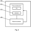
- Fig. 4 shows a schematic illustration of a main controller 110 or a dedicated RCU controller 132.
- the controller 400 may include at least one nontransitory processor-readable storage medium 410 that stores at least one of processor-executable instructions 415 or data (such as authorized user voice identifiers, activation phrase, paired RCU identifier(s)); and at least one processor 420 communicably coupled to the at least one nontransitory processor-readable storage medium 410.
- the at least one processor 420 may be configured to (by executing the instructions 415) perform the corresponding steps of the method of Fig. 3 (i.e. steps 301, 302, 303, 304 for the voice interface 120 or steps 305, 306, 307 for the RCU interface).
Landscapes
- Engineering & Computer Science (AREA)
- Computer Networks & Wireless Communication (AREA)
- Physics & Mathematics (AREA)
- General Physics & Mathematics (AREA)
- Selective Calling Equipment (AREA)
Abstract
Description
- The present invention relates to a device that can be paired with a remote controller.
- Electronic devices are nowadays controlled by a variety of interfaces: local (such as a keypad, a touch screen) or remote (such as a wireless controller, voice, gestures). The number of electronic devices surrounding users increases.
- When many devices are located in a close proximity to each other, there appears a problem of effective control of the devices, such that a command send from a user to one particular device is not received by another one.
- For example, there may be a plurality of television sets in a school classroom, a hotel lobby or a hospital room. Such TV sets are typically controlled by remote control units (RCUs). The RCUs should be paired with particular TV sets such that one user does not accidentally control a TV set of another user. There are mechanisms for pairing an RCU with a device, which can be initiated by special device setup procedures, which require at least a minimum level of technical skills. These procedures can be troublesome and time-consuming for at least some users who are not technically skilled.
- Therefore, there is a need to provide a device that can be efficiently paired with a remote controller.
- The invention relates to a remote-controlled device, the device comprising a voice interface, a remote controller interface and a controller; wherein the device is configured to: receive, via the voice interface, an activation phrase; check whether the application phrase is received from within an allowable activation angle; if so, receive, via the remote controller interface, a command from the remote controller, wherein the command includes a remote controller identifier; store the remote controller identifier as an identifier of a paired remote controller.
- Preferably, the allowable activation angle is user-defined.
- Preferably, the allowable activation angle is smaller than 180 degrees, or smaller than 120 degrees, or smaller than 90 degrees, or smaller than 60 degrees, or smaller than 45 degrees, or smaller than 30 degrees, or smaller than 20 degrees, or smaller than 10 degrees.
- Preferably, the device is further configured to recognize a user via the voice interface and accept the activation phrase only from an authorized user.
- Preferably, the remote controller communicates via an infrared signal.
- Preferably, the remote controller communicates via a Bluetooth channel.
- The invention also relates to a arrangement of devices as described herein, positioned in a vicinity to each other, wherein the allowable activation angle is smaller than 120 degrees, or smaller than 90 degrees, or smaller than 60 degrees, or smaller than 45 degrees, or smaller than 30 degrees, or smaller than 20 degrees, or smaller than 10 degrees.
- The present invention will be shown by means of example embodiments on a drawing, wherein:
-
Fig. 1 shows a place with a plurality of voice-controlled devices in which the present system is usable; -
Fig. 2 shows a structure of a voice-controlled device controllable by the RCU; -
Fig. 3 shows a method for pairing the RCU with the device; -
Fig. 4 shows a schematic representation of a controller. - Some portions of the detailed description which follows are presented in terms of data processing procedures, steps or other symbolic representations of operations on data bits that can be performed on computer memory. Therefore, a computer executes such logical steps thus requiring physical manipulations of physical quantities.
- Usually these quantities take the form of electrical or magnetic signals capable of being stored, transferred, combined, compared, and otherwise manipulated in a computer system. For reasons of common usage, these signals are referred to as bits, packets, messages, values, elements, symbols, characters, terms, numbers, or the like.
- Additionally, all of these and similar terms are to be associated with the appropriate physical quantities and are merely convenient labels applied to these quantities. Terms such as "processing" or "creating" or "transferring" or "executing" or "determining" or "detecting" or "obtaining" or "selecting" or "calculating" or "generating" or the like, refer to the action and processes of a computer system that manipulates and transforms data represented as physical (electronic) quantities within the computer's registers and memories into other data similarly represented as physical quantities within the memories or registers or other such information storage.
- A computer-readable (storage) medium, such as referred to herein, typically may be non-transitory and/or comprise a non-transitory device. In this context, a non-transitory storage medium may include a device that may be tangible, meaning that the device has a concrete physical form, although the device may change its physical state. Thus, for example, non-transitory refers to a device remaining tangible despite a change in state.
- The present invention is useful in a situation as shown in
Fig. 1 , wherein there are a plurality ofdevices devices - Each device should be paired with a particular remote controller (also called a remote control unit, RCU) for controlling the device. There are some situations when the RCUs may get easily mixed and frequent pairing of the RCU with the device is necessary.
- For example, if there are a plurality of TV sets in a room visited by many users, the users may walk around the room and leave the RCU in different places that are far from the device. If someone grabs a RCU left by a different user, that new user may not be aware which device will be controlled by that RCU. This can happen for example in a hotel lobby with a plurality of TV sets or in a gaming room with a plurality of game consoles (wherein the RCU is a game pad).
- Another example is a hotel wherein each room has a TV set controlled by a RCU. It sometimes happens that the visitors take away the RCUs and a new RCU must be supplied to allow a new visitor to control the TV set - and the new RCU must be effectively paired with the TV set.
- The present invention takes advantage of a voice control interface that is nowadays present in more and more devices.
- A structure of a device is shown in
Fig. 2 . Thedevice 100 comprises amain controller 110 that is configured to provide the basic functionality of the device (such as playing a TV signal for a TV set or a TV set back box, running a game for a game console, playing audio for a Hi-Fi set, or providing general purpose tasks for a personal computer). Themain controller 110 has at least two control interfaces that are applicable for the present invention: avoice control interface 120 and a remotecontrol unit interface 130. Thevoice control interface 120 typically comprises a pair ofmicrophones sound direction detector 123. Thesound direction detector 123 is configured to determine the direction from which the sound (e.g. user's voice) received by themicrophones control unit interface 130 comprises asignal receiver 131 to receive signal emitted by the RCU, such as an IR signal or a Bluetooth signal. - The RCU pairing procedure is shown in
Fig. 3 . It comprises steps to be taken by the voice interface 120 (on the left) and the RCU interface 130 (on the right). These actions can be performed by programs controlling these interfaces, which can be executed by dedicated controllers for these interfaces (in particular, the RCU pairing controller 132) or by themain controller 110. - The procedure is initiated in
step 301 by recognizing, by thevoice interface 120, a special activating phrase (which can be a single word) spoken by the user, such as "pair my remote". This activating phrase may be a default phrase or a secret phrase defined by the user when setting up thedevice 100. Thevoice interface 120 may be further configured to be activated only by the activating phrase spoken by a particular user (such as a hotel personnel), if thevoice interface 120 has capabilities to recognize users by voice. - In
step 302 thevoice interface 120 checks from which direction the phrase was received. Eachdevice specific activation angle activation angle device user 41 that is located substantially in front of thatdevice 11, as shown inFig. 1 . This way only asingle device 11 accepts the activating phrase instep 303 and theother devices step 304. This limits the risk that the user will unintentionally activate the RCU 51 withother devices - Once the request is accepted, the device awaits the user to activate the RCU that is to be paired with the device.
- In order to notify the user that the activation phrase was detected, the RCU interface may ask the user in
step 305 to activate the RCU, for example by blinking a diode or sending a command to other interfaces to inform the user (e.g. a command to a display interface to display a sign or a command to an audio interface to play a sound, wherein the sign or sound may be "Please use your RCU"). - In
step 306 the RCU interface awaits to receive a command from the RCU. This can be any command or a specific command, such as corresponding to a particular RCU button, preferably a button that is rarely used so as to avoid accidental activations (e.g. a yellow button on a TV set RCU). Typically, in IR or Bluetooth RCU, when a button is pressed, the RCU sends a signal that includes the RCU identifier and the command. Then, instep 307, the RCU interface stores the RCU identifier that was just received as the identifier of the RCU that is allowed to control this particular device. TheRCU interface 130 may be configured to be operated by a single RCU (in that case, the recently received RCU identifier replaces the previously stored identifier) or by a plurality of RCU (in that case, the recently received RCU identifier is added to the list of accepted RCUs). - Next, the device continues its operation and can be controlled by the recently activated RCU.
-
Fig. 4 shows a schematic illustration of amain controller 110 or adedicated RCU controller 132. Thecontroller 400 may include at least one nontransitory processor-readable storage medium 410 that stores at least one of processor-executable instructions 415 or data (such as authorized user voice identifiers, activation phrase, paired RCU identifier(s)); and at least oneprocessor 420 communicably coupled to the at least one nontransitory processor-readable storage medium 410. The at least oneprocessor 420 may be configured to (by executing the instructions 415) perform the corresponding steps of the method ofFig. 3 (i.e. steps 301, 302, 303, 304 for thevoice interface 120 orsteps - The presented solution makes the process of RCU pairing very easy and intuitive. A user that wishes to operate a device with a new RCU simply stands in front of the device, utters the activation phrase and enters a button of the RCU. No navigation via system settings is necessary.
- While the invention presented herein has been depicted, described, and has been defined with reference to particular preferred embodiments, such references and examples of implementation in the foregoing specification do not imply any limitation on the invention. It will, however, be evident that various modifications and changes may be made thereto without departing from the broader scope of the technical concept. The presented preferred embodiments are exemplary only, and are not exhaustive of the scope of the technical concept presented herein.
- Accordingly, the scope of protection is not limited to the preferred embodiments described in the specification, but is only limited by the claims that follow.
Claims (7)
- A remote-controlled device (100), the device comprising a voice interface (120), a remote controller interface (130) and a controller (110); wherein the device is configured to:- receive (301), via the voice interface (120), an activation phrase;- check (302) whether the application phrase is received from within an allowable activation angle;- if so, receive (306), via the remote controller interface (130), a command from the remote controller (51), wherein the command includes a remote controller identifier;- store (307) the remote controller identifier as an identifier of a paired remote controller.
- The device according to claim 1, wherein the allowable activation angle (12, 22, 32) is user-defined.
- The device according to any of previous claims, wherein the allowable activation angle (12, 22, 32) is smaller than 180 degrees, or smaller than 120 degrees, or smaller than 90 degrees, or smaller than 60 degrees, or smaller than 45 degrees, or smaller than 30 degrees, or smaller than 20 degrees, or smaller than 10 degrees.
- The device according to any of previous claims, wherein the device is further configured to recognize a user via the voice interface (120) and accept the activation phrase only from an authorized user.
- The device according to any of previous claims, wherein the remote controller (51) communicates via an infrared signal.
- The device according to any of previous claims, wherein the remote controller (51) communicates via a Bluetooth channel.
- An arrangement of devices (11, 21, 31) according to any of previous claims positioned in a vicinity to each other, wherein the allowable activation angle is smaller than 120 degrees, or smaller than 90 degrees, or smaller than 60 degrees, or smaller than 45 degrees, or smaller than 30 degrees, or smaller than 20 degrees, or smaller than 10 degrees.
Priority Applications (1)
| Application Number | Priority Date | Filing Date | Title |
|---|---|---|---|
| EP20217942.0A EP4024359B1 (en) | 2020-12-30 | 2020-12-30 | A remote-controlled device |
Applications Claiming Priority (1)
| Application Number | Priority Date | Filing Date | Title |
|---|---|---|---|
| EP20217942.0A EP4024359B1 (en) | 2020-12-30 | 2020-12-30 | A remote-controlled device |
Publications (2)
| Publication Number | Publication Date |
|---|---|
| EP4024359A1 true EP4024359A1 (en) | 2022-07-06 |
| EP4024359B1 EP4024359B1 (en) | 2025-07-16 |
Family
ID=74045386
Family Applications (1)
| Application Number | Title | Priority Date | Filing Date |
|---|---|---|---|
| EP20217942.0A Active EP4024359B1 (en) | 2020-12-30 | 2020-12-30 | A remote-controlled device |
Country Status (1)
| Country | Link |
|---|---|
| EP (1) | EP4024359B1 (en) |
Citations (2)
| Publication number | Priority date | Publication date | Assignee | Title |
|---|---|---|---|---|
| US20060282649A1 (en) * | 2005-06-10 | 2006-12-14 | Malamud Mark A | Device pairing via voice commands |
| US20130308506A1 (en) * | 2012-05-18 | 2013-11-21 | Qualcomm Incorporated | Automatic device-to-device connection control by environmental information |
-
2020
- 2020-12-30 EP EP20217942.0A patent/EP4024359B1/en active Active
Patent Citations (2)
| Publication number | Priority date | Publication date | Assignee | Title |
|---|---|---|---|---|
| US20060282649A1 (en) * | 2005-06-10 | 2006-12-14 | Malamud Mark A | Device pairing via voice commands |
| US20130308506A1 (en) * | 2012-05-18 | 2013-11-21 | Qualcomm Incorporated | Automatic device-to-device connection control by environmental information |
Also Published As
| Publication number | Publication date |
|---|---|
| EP4024359B1 (en) | 2025-07-16 |
Similar Documents
| Publication | Publication Date | Title |
|---|---|---|
| US9368105B1 (en) | Preventing false wake word detections with a voice-controlled device | |
| US12026314B2 (en) | Haptic feedback remote control systems and methods | |
| US8552832B2 (en) | System and method for interactive appliance control | |
| US20260122171A1 (en) | Portable terminal apparatus | |
| US20150186017A1 (en) | Unlocking method and device using tension effect | |
| KR20150099259A (en) | Electronic device and method for recognizing biometrics information | |
| CN105320268B (en) | Device and method for controlling device by user | |
| US20180270525A1 (en) | Display device and operating method therefor | |
| KR20230098315A (en) | Systems, methods and media for inputting obfuscated personal identification numbers into media devices | |
| US9078088B2 (en) | System and method for transport layer agnostic programming interface for use with smartphones | |
| EP4024358B1 (en) | A method for pairing a remote controller with a device | |
| US20160349843A1 (en) | Remote control apparatus, method of providing vibration feedback thereof, and display system | |
| KR102527278B1 (en) | Electronic apparatus, method for controlling thereof and the computer readable recording medium | |
| US20180261221A1 (en) | System and method for controlling physical objects placed on an interactive board with voice commands | |
| EP4024359B1 (en) | A remote-controlled device | |
| WO2016063621A1 (en) | Control device, control method, program and information storage medium | |
| CN107450806A (en) | Shortcut menu display methods, mobile terminal and the device with store function | |
| US20180373695A1 (en) | Accessibility menu from remote control | |
| EP3247119A1 (en) | Media system and method for implementing various modes using force input | |
| JP6257040B2 (en) | Karaoke system, portable information processing apparatus and program | |
| KR20030046094A (en) | Remote control device and method based on motion recognition of the same | |
| US9030406B2 (en) | Remote control functionality including information from motion sensors | |
| CN111857514A (en) | Device control method, device, electronic device and storage medium | |
| US20170304723A1 (en) | System and method for providing a software application controller | |
| US10051331B1 (en) | Quick accessibility profiles |
Legal Events
| Date | Code | Title | Description |
|---|---|---|---|
| PUAI | Public reference made under article 153(3) epc to a published international application that has entered the european phase |
Free format text: ORIGINAL CODE: 0009012 |
|
| STAA | Information on the status of an ep patent application or granted ep patent |
Free format text: STATUS: THE APPLICATION HAS BEEN PUBLISHED |
|
| AK | Designated contracting states |
Kind code of ref document: A1 Designated state(s): AL AT BE BG CH CY CZ DE DK EE ES FI FR GB GR HR HU IE IS IT LI LT LU LV MC MK MT NL NO PL PT RO RS SE SI SK SM TR |
|
| STAA | Information on the status of an ep patent application or granted ep patent |
Free format text: STATUS: REQUEST FOR EXAMINATION WAS MADE |
|
| 17P | Request for examination filed |
Effective date: 20230104 |
|
| RBV | Designated contracting states (corrected) |
Designated state(s): AL AT BE BG CH CY CZ DE DK EE ES FI FR GB GR HR HU IE IS IT LI LT LU LV MC MK MT NL NO PL PT RO RS SE SI SK SM TR |
|
| GRAP | Despatch of communication of intention to grant a patent |
Free format text: ORIGINAL CODE: EPIDOSNIGR1 |
|
| STAA | Information on the status of an ep patent application or granted ep patent |
Free format text: STATUS: GRANT OF PATENT IS INTENDED |
|
| INTG | Intention to grant announced |
Effective date: 20250226 |
|
| GRAS | Grant fee paid |
Free format text: ORIGINAL CODE: EPIDOSNIGR3 |
|
| GRAA | (expected) grant |
Free format text: ORIGINAL CODE: 0009210 |
|
| STAA | Information on the status of an ep patent application or granted ep patent |
Free format text: STATUS: THE PATENT HAS BEEN GRANTED |
|
| AK | Designated contracting states |
Kind code of ref document: B1 Designated state(s): AL AT BE BG CH CY CZ DE DK EE ES FI FR GB GR HR HU IE IS IT LI LT LU LV MC MK MT NL NO PL PT RO RS SE SI SK SM TR |
|
| REG | Reference to a national code |
Ref country code: GB Ref legal event code: FG4D |
|
| REG | Reference to a national code |
Ref country code: CH Ref legal event code: EP |
|
| REG | Reference to a national code |
Ref country code: DE Ref legal event code: R096 Ref document number: 602020054540 Country of ref document: DE |
|
| REG | Reference to a national code |
Ref country code: IE Ref legal event code: FG4D |
|
| REG | Reference to a national code |
Ref country code: NL Ref legal event code: MP Effective date: 20250716 |
|
| PG25 | Lapsed in a contracting state [announced via postgrant information from national office to epo] |
Ref country code: PT Free format text: LAPSE BECAUSE OF FAILURE TO SUBMIT A TRANSLATION OF THE DESCRIPTION OR TO PAY THE FEE WITHIN THE PRESCRIBED TIME-LIMIT Effective date: 20251117 |
|
| PG25 | Lapsed in a contracting state [announced via postgrant information from national office to epo] |
Ref country code: NL Free format text: LAPSE BECAUSE OF FAILURE TO SUBMIT A TRANSLATION OF THE DESCRIPTION OR TO PAY THE FEE WITHIN THE PRESCRIBED TIME-LIMIT Effective date: 20250716 |
|
| REG | Reference to a national code |
Ref country code: AT Ref legal event code: MK05 Ref document number: 1814803 Country of ref document: AT Kind code of ref document: T Effective date: 20250716 |
|
| PG25 | Lapsed in a contracting state [announced via postgrant information from national office to epo] |
Ref country code: IS Free format text: LAPSE BECAUSE OF FAILURE TO SUBMIT A TRANSLATION OF THE DESCRIPTION OR TO PAY THE FEE WITHIN THE PRESCRIBED TIME-LIMIT Effective date: 20251116 |
|
| PGFP | Annual fee paid to national office [announced via postgrant information from national office to epo] |
Ref country code: GB Payment date: 20251229 Year of fee payment: 6 |
|
| PG25 | Lapsed in a contracting state [announced via postgrant information from national office to epo] |
Ref country code: NO Free format text: LAPSE BECAUSE OF FAILURE TO SUBMIT A TRANSLATION OF THE DESCRIPTION OR TO PAY THE FEE WITHIN THE PRESCRIBED TIME-LIMIT Effective date: 20251016 |
|
| REG | Reference to a national code |
Ref country code: LT Ref legal event code: MG9D |
|
| PG25 | Lapsed in a contracting state [announced via postgrant information from national office to epo] |
Ref country code: AT Free format text: LAPSE BECAUSE OF FAILURE TO SUBMIT A TRANSLATION OF THE DESCRIPTION OR TO PAY THE FEE WITHIN THE PRESCRIBED TIME-LIMIT Effective date: 20250716 |
|
| PG25 | Lapsed in a contracting state [announced via postgrant information from national office to epo] |
Ref country code: FI Free format text: LAPSE BECAUSE OF FAILURE TO SUBMIT A TRANSLATION OF THE DESCRIPTION OR TO PAY THE FEE WITHIN THE PRESCRIBED TIME-LIMIT Effective date: 20250716 |
|
| PG25 | Lapsed in a contracting state [announced via postgrant information from national office to epo] |
Ref country code: HR Free format text: LAPSE BECAUSE OF FAILURE TO SUBMIT A TRANSLATION OF THE DESCRIPTION OR TO PAY THE FEE WITHIN THE PRESCRIBED TIME-LIMIT Effective date: 20250716 |
|
| PGFP | Annual fee paid to national office [announced via postgrant information from national office to epo] |
Ref country code: FR Payment date: 20251226 Year of fee payment: 6 |
|
| PG25 | Lapsed in a contracting state [announced via postgrant information from national office to epo] |
Ref country code: GR Free format text: LAPSE BECAUSE OF FAILURE TO SUBMIT A TRANSLATION OF THE DESCRIPTION OR TO PAY THE FEE WITHIN THE PRESCRIBED TIME-LIMIT Effective date: 20251017 |
|
| PG25 | Lapsed in a contracting state [announced via postgrant information from national office to epo] |
Ref country code: SE Free format text: LAPSE BECAUSE OF FAILURE TO SUBMIT A TRANSLATION OF THE DESCRIPTION OR TO PAY THE FEE WITHIN THE PRESCRIBED TIME-LIMIT Effective date: 20250716 |
|
| PG25 | Lapsed in a contracting state [announced via postgrant information from national office to epo] |
Ref country code: LV Free format text: LAPSE BECAUSE OF FAILURE TO SUBMIT A TRANSLATION OF THE DESCRIPTION OR TO PAY THE FEE WITHIN THE PRESCRIBED TIME-LIMIT Effective date: 20250716 |
|
| PG25 | Lapsed in a contracting state [announced via postgrant information from national office to epo] |
Ref country code: BG Free format text: LAPSE BECAUSE OF FAILURE TO SUBMIT A TRANSLATION OF THE DESCRIPTION OR TO PAY THE FEE WITHIN THE PRESCRIBED TIME-LIMIT Effective date: 20250716 Ref country code: PL Free format text: LAPSE BECAUSE OF FAILURE TO SUBMIT A TRANSLATION OF THE DESCRIPTION OR TO PAY THE FEE WITHIN THE PRESCRIBED TIME-LIMIT Effective date: 20250716 |
|
| PG25 | Lapsed in a contracting state [announced via postgrant information from national office to epo] |
Ref country code: RS Free format text: LAPSE BECAUSE OF FAILURE TO SUBMIT A TRANSLATION OF THE DESCRIPTION OR TO PAY THE FEE WITHIN THE PRESCRIBED TIME-LIMIT Effective date: 20251016 |
|
| PG25 | Lapsed in a contracting state [announced via postgrant information from national office to epo] |
Ref country code: ES Free format text: LAPSE BECAUSE OF FAILURE TO SUBMIT A TRANSLATION OF THE DESCRIPTION OR TO PAY THE FEE WITHIN THE PRESCRIBED TIME-LIMIT Effective date: 20250716 |
|
| PG25 | Lapsed in a contracting state [announced via postgrant information from national office to epo] |
Ref country code: RO Free format text: LAPSE BECAUSE OF FAILURE TO SUBMIT A TRANSLATION OF THE DESCRIPTION OR TO PAY THE FEE WITHIN THE PRESCRIBED TIME-LIMIT Effective date: 20250716 |
|
| PG25 | Lapsed in a contracting state [announced via postgrant information from national office to epo] |
Ref country code: SM Free format text: LAPSE BECAUSE OF FAILURE TO SUBMIT A TRANSLATION OF THE DESCRIPTION OR TO PAY THE FEE WITHIN THE PRESCRIBED TIME-LIMIT Effective date: 20250716 |
|
| PG25 | Lapsed in a contracting state [announced via postgrant information from national office to epo] |
Ref country code: DK Free format text: LAPSE BECAUSE OF FAILURE TO SUBMIT A TRANSLATION OF THE DESCRIPTION OR TO PAY THE FEE WITHIN THE PRESCRIBED TIME-LIMIT Effective date: 20250716 |
|
| PGFP | Annual fee paid to national office [announced via postgrant information from national office to epo] |
Ref country code: DE Payment date: 20251229 Year of fee payment: 6 |
|
| PG25 | Lapsed in a contracting state [announced via postgrant information from national office to epo] |
Ref country code: IT Free format text: LAPSE BECAUSE OF FAILURE TO SUBMIT A TRANSLATION OF THE DESCRIPTION OR TO PAY THE FEE WITHIN THE PRESCRIBED TIME-LIMIT Effective date: 20250716 |
|
| PG25 | Lapsed in a contracting state [announced via postgrant information from national office to epo] |
Ref country code: CZ Free format text: LAPSE BECAUSE OF FAILURE TO SUBMIT A TRANSLATION OF THE DESCRIPTION OR TO PAY THE FEE WITHIN THE PRESCRIBED TIME-LIMIT Effective date: 20250716 |
|
| PG25 | Lapsed in a contracting state [announced via postgrant information from national office to epo] |
Ref country code: EE Free format text: LAPSE BECAUSE OF FAILURE TO SUBMIT A TRANSLATION OF THE DESCRIPTION OR TO PAY THE FEE WITHIN THE PRESCRIBED TIME-LIMIT Effective date: 20250716 Ref country code: SK Free format text: LAPSE BECAUSE OF FAILURE TO SUBMIT A TRANSLATION OF THE DESCRIPTION OR TO PAY THE FEE WITHIN THE PRESCRIBED TIME-LIMIT Effective date: 20250716 |