EP4024340A1 - System for refining a six degrees of freedom pose estimate of a target object - Google Patents
System for refining a six degrees of freedom pose estimate of a target object Download PDFInfo
- Publication number
- EP4024340A1 EP4024340A1 EP21216303.4A EP21216303A EP4024340A1 EP 4024340 A1 EP4024340 A1 EP 4024340A1 EP 21216303 A EP21216303 A EP 21216303A EP 4024340 A1 EP4024340 A1 EP 4024340A1
- Authority
- EP
- European Patent Office
- Prior art keywords
- degrees
- pose estimate
- target object
- freedom pose
- sensing device
- Prior art date
- Legal status (The legal status is an assumption and is not a legal conclusion. Google has not performed a legal analysis and makes no representation as to the accuracy of the status listed.)
- Granted
Links
Images



Classifications
-
- G—PHYSICS
- G01—MEASURING; TESTING
- G01S—RADIO DIRECTION-FINDING; RADIO NAVIGATION; DETERMINING DISTANCE OR VELOCITY BY USE OF RADIO WAVES; LOCATING OR PRESENCE-DETECTING BY USE OF THE REFLECTION OR RERADIATION OF RADIO WAVES; ANALOGOUS ARRANGEMENTS USING OTHER WAVES
- G01S17/00—Systems using the reflection or reradiation of electromagnetic waves other than radio waves, e.g. lidar systems
- G01S17/02—Systems using the reflection of electromagnetic waves other than radio waves
- G01S17/06—Systems determining position data of a target
- G01S17/08—Systems determining position data of a target for measuring distance only
-
- G—PHYSICS
- G06—COMPUTING OR CALCULATING; COUNTING
- G06T—IMAGE DATA PROCESSING OR GENERATION, IN GENERAL
- G06T7/00—Image analysis
- G06T7/70—Determining position or orientation of objects or cameras
-
- B—PERFORMING OPERATIONS; TRANSPORTING
- B64—AIRCRAFT; AVIATION; COSMONAUTICS
- B64D—EQUIPMENT FOR FITTING IN OR TO AIRCRAFT; FLIGHT SUITS; PARACHUTES; ARRANGEMENT OR MOUNTING OF POWER PLANTS OR PROPULSION TRANSMISSIONS IN AIRCRAFT
- B64D39/00—Refuelling during flight
-
- G—PHYSICS
- G01—MEASURING; TESTING
- G01C—MEASURING DISTANCES, LEVELS OR BEARINGS; SURVEYING; NAVIGATION; GYROSCOPIC INSTRUMENTS; PHOTOGRAMMETRY OR VIDEOGRAMMETRY
- G01C21/00—Navigation; Navigational instruments not provided for in groups G01C1/00 - G01C19/00
- G01C21/10—Navigation; Navigational instruments not provided for in groups G01C1/00 - G01C19/00 by using measurements of speed or acceleration
- G01C21/12—Navigation; Navigational instruments not provided for in groups G01C1/00 - G01C19/00 by using measurements of speed or acceleration executed aboard the object being navigated; Dead reckoning
- G01C21/16—Navigation; Navigational instruments not provided for in groups G01C1/00 - G01C19/00 by using measurements of speed or acceleration executed aboard the object being navigated; Dead reckoning by integrating acceleration or speed, i.e. inertial navigation
- G01C21/165—Navigation; Navigational instruments not provided for in groups G01C1/00 - G01C19/00 by using measurements of speed or acceleration executed aboard the object being navigated; Dead reckoning by integrating acceleration or speed, i.e. inertial navigation combined with non-inertial navigation instruments
- G01C21/1652—Navigation; Navigational instruments not provided for in groups G01C1/00 - G01C19/00 by using measurements of speed or acceleration executed aboard the object being navigated; Dead reckoning by integrating acceleration or speed, i.e. inertial navigation combined with non-inertial navigation instruments with ranging devices, e.g. LIDAR or RADAR
-
- G—PHYSICS
- G01—MEASURING; TESTING
- G01S—RADIO DIRECTION-FINDING; RADIO NAVIGATION; DETERMINING DISTANCE OR VELOCITY BY USE OF RADIO WAVES; LOCATING OR PRESENCE-DETECTING BY USE OF THE REFLECTION OR RERADIATION OF RADIO WAVES; ANALOGOUS ARRANGEMENTS USING OTHER WAVES
- G01S15/00—Systems using the reflection or reradiation of acoustic waves, e.g. sonar systems
- G01S15/02—Systems using the reflection or reradiation of acoustic waves, e.g. sonar systems using reflection of acoustic waves
- G01S15/06—Systems determining the position data of a target
- G01S15/08—Systems for measuring distance only
-
- G—PHYSICS
- G01—MEASURING; TESTING
- G01S—RADIO DIRECTION-FINDING; RADIO NAVIGATION; DETERMINING DISTANCE OR VELOCITY BY USE OF RADIO WAVES; LOCATING OR PRESENCE-DETECTING BY USE OF THE REFLECTION OR RERADIATION OF RADIO WAVES; ANALOGOUS ARRANGEMENTS USING OTHER WAVES
- G01S17/00—Systems using the reflection or reradiation of electromagnetic waves other than radio waves, e.g. lidar systems
- G01S17/88—Lidar systems specially adapted for specific applications
- G01S17/89—Lidar systems specially adapted for specific applications for mapping or imaging
-
- G—PHYSICS
- G06—COMPUTING OR CALCULATING; COUNTING
- G06T—IMAGE DATA PROCESSING OR GENERATION, IN GENERAL
- G06T7/00—Image analysis
- G06T7/30—Determination of transform parameters for the alignment of images, i.e. image registration
-
- G—PHYSICS
- G06—COMPUTING OR CALCULATING; COUNTING
- G06V—IMAGE OR VIDEO RECOGNITION OR UNDERSTANDING
- G06V10/00—Arrangements for image or video recognition or understanding
- G06V10/40—Extraction of image or video features
-
- G—PHYSICS
- G06—COMPUTING OR CALCULATING; COUNTING
- G06T—IMAGE DATA PROCESSING OR GENERATION, IN GENERAL
- G06T2207/00—Indexing scheme for image analysis or image enhancement
- G06T2207/10—Image acquisition modality
- G06T2207/10004—Still image; Photographic image
-
- G—PHYSICS
- G06—COMPUTING OR CALCULATING; COUNTING
- G06T—IMAGE DATA PROCESSING OR GENERATION, IN GENERAL
- G06T2207/00—Indexing scheme for image analysis or image enhancement
- G06T2207/10—Image acquisition modality
- G06T2207/10028—Range image; Depth image; 3D point clouds
-
- G—PHYSICS
- G06—COMPUTING OR CALCULATING; COUNTING
- G06T—IMAGE DATA PROCESSING OR GENERATION, IN GENERAL
- G06T2207/00—Indexing scheme for image analysis or image enhancement
- G06T2207/20—Special algorithmic details
- G06T2207/20084—Artificial neural networks [ANN]
-
- G—PHYSICS
- G06—COMPUTING OR CALCULATING; COUNTING
- G06T—IMAGE DATA PROCESSING OR GENERATION, IN GENERAL
- G06T2207/00—Indexing scheme for image analysis or image enhancement
- G06T2207/30—Subject of image; Context of image processing
- G06T2207/30248—Vehicle exterior or interior
-
- G—PHYSICS
- G06—COMPUTING OR CALCULATING; COUNTING
- G06T—IMAGE DATA PROCESSING OR GENERATION, IN GENERAL
- G06T2207/00—Indexing scheme for image analysis or image enhancement
- G06T2207/30—Subject of image; Context of image processing
- G06T2207/30248—Vehicle exterior or interior
- G06T2207/30252—Vehicle exterior; Vicinity of vehicle
Definitions
- the present disclosure relates to a system and method of refining a six degrees of freedom pose estimate of a target object. More particularly, the present disclosure is directed towards a system and method of refining a six degrees of freedom pose estimate of the target object based on a single one-dimensional measurement.
- Six degrees of freedom refers to the freedom of movement of a rigid body in three-dimensional space.
- the rigid body may move in three dimensions, on the x, y and z axes, as well as change orientation between the three axes though rotation, which are referred to as pitch, roll, and yaw.
- Image-based pose estimation systems may estimate a six degrees of freedom pose of an object. Furthermore, many image-based pose estimation systems also utilize some type of refinement process for revising an initial six degrees of freedom pose estimate.
- Some types of pose estimate refinement processes utilize a three-dimension depth map or, in the alternative, numerous two-dimension distance measurements where a laser range finder is used to take the two-dimensional distance measurements. However, both the three-dimensional depth map and the two-dimensional distance measurements typically require significant processing and memory allocation requirements.
- the laser range finder used in the two-dimensional distance measurement approach may require precisely manufactured moving parts in order to maintain consistent two-dimensional distance measurements, which in turn adds cost to the system.
- some types of pose estimate refinement approaches may require specialized calibration patterns or correspondence markers for registering the scan lines of the laser range finder with corresponding features that are part of a model.
- a system for refining a six degrees of freedom pose estimate of a target object based on a one-dimensional measurement includes a camera configured to capture image data of the target object and a range-sensing device configured to determine an actual distance measured between the range-sensing device and an actual point of intersection.
- the range-sensing device projects a line-of-sight that intersects with the target object at the actual point of intersection.
- the system also includes one or more processors in electronic communication with the camera and the range-sensing device as well as a memory coupled to the one or more processors.
- the memory stores data into one or more databases and program code that, when executed by the one or more processors, causes the system to predict, based on the image data of the target object, the six degrees of freedom pose estimate of the target object.
- the system determines an estimated point of intersection representing where the line-of-sight intersects with the six degrees of freedom pose estimate of the target object.
- the system also determines an estimated distance measured between the range-sensing device and the estimated point of intersection.
- the system calculates an absolute error associated with the six degrees of freedom pose estimate of the target object based on a difference between the actual distance and the estimated distance.
- the system determines a revised six degrees of freedom pose estimate of the target object based on at least the absolute error.
- the aerial refueling system includes a boom assembly including a nozzle and a system for determining a revised six degrees of freedom pose estimate of a fuel receptacle located on a receiver aircraft.
- the nozzle of the boom assembly is configured to engage with a fuel receptacle of the receiver aircraft during a refueling operation.
- the system includes a camera configured to capture image data of the receiver aircraft and the fuel receptacle and a range-sensing device configured to determine an actual distance measured between the range-sensing device and an actual point of intersection.
- the range-sensing device projects a line-of-sight that intersects with the receiver aircraft at the actual point of intersection.
- the system also includes one or more processors in electronic communication with the camera and the range-sensing device and a memory coupled to the one or more processors.
- the memory stores data into one or more databases and program code that, when executed by the one or more processors, causes the system to predict, based on the image data of the fuel receptacle located on a receiver aircraft, the six degrees of freedom pose estimate of the fuel receptacle located on the receiver aircraft.
- the system determines an estimated point of intersection representing where the line-of-sight intersects with the six degrees of freedom pose estimate of the receiver aircraft.
- the system determines an estimated distance measured between the range-sensing device and the estimated point of intersection.
- the system calculates an absolute error associated with the six degrees of freedom pose estimate of the fuel receptacle located on the receiver aircraft based on a difference between the actual distance and the estimated distance. The system then determines a revised six degrees of freedom pose estimate based on at least the absolute error.
- a method for refining a six degrees of freedom pose estimate of a target object includes capturing, by a camera, image data of the target object.
- the method also includes determining, by a range-sensing device, an actual distance measured between the range-sensing device and an actual point of intersection, where the range-sensing device projects a line-of-sight that intersects with the target object at the actual point of intersection.
- the method also includes predicting, based on the image data of the target object, the six degrees of freedom pose estimate of the target object.
- the method further includes determining an estimated point of intersection representing where the line-of-sight intersects with the six degrees of freedom pose estimate of the target object.
- the method further includes determining an estimated distance measured between the range-sensing device and the estimated point of intersection.
- the method also includes calculating an absolute error associated with the six degrees of freedom pose estimate of the target object based on a difference between the actual distance and the estimated distance.
- the method includes determining a revised six degree of freedom pose estimate based on at least the absolute error.
- the present disclosure relates to a system and method of refining a six degrees of freedom pose estimate of a target object based on a single one-dimensional measurement.
- the system includes a control module in electronic communication with a camera and a range-sensing device.
- the camera is configured to capture image data of the target object
- the range-sensing device is configured to determine the one-dimensional measurement.
- the range-sensing device determines an actual distance measured between the range-sensing device and an actual point of intersection W'. Specifically, the actual point of intersection W' represents where a line-of-sight projected by the range-sensing device intersects with the target object.
- the system determines the six degrees of freedom pose estimate of the target object based on the image data captured by the camera.
- the system determines an estimated point of intersection representing where the line-of-sight intersects with the six degrees of freedom pose estimate of the target object.
- the system determines an estimated distance measured between the range-sensing device and the estimated point of intersection.
- the system calculates an absolute error based on a difference between the actual distance and the estimated distance.
- the system also determines a reprojection error introduced by the six degrees of freedom pose estimate of the target object.
- the system determines a revised pose estimate of the target object based on the absolute error and, if available, the reprojection error.
- a system 10 for refining a six degrees of freedom pose estimate 8 (seen in FIG. 2 ) of a target object 12 is illustrated.
- the system 10 is part of an aerial refueling system 14 located at a tail section 16 of a tanker or supply aircraft 18.
- the aerial refueling system 14 includes a boom assembly 20 connected to a fuselage 22 of the supply aircraft 18 at an articulating joint 24.
- the boom assembly 20 includes a rigid portion 26, a telescoping extension 28, and a nozzle 30.
- the nozzle 30 of the boom assembly 20 is engaged with a fuel receptacle 32 of a receiver aircraft 34 during a refueling operation.
- the receiver aircraft 34 and in particular the fuel receptacle 32, represent the target object 12. Accordingly, the system 10 refines the six degrees of freedom pose estimate 8 ( FIG. 2 ) of the fuel receptacle 32 and the receiver aircraft 34.
- the system 10 includes a control module 40 in electronic communication with a camera 42 and a range-sensing device 44.
- the camera 42 is positioned in a location to capture image data of the target object 12 (i.e., the fuel receptacle 32 and the receiver aircraft 34).
- the control module 40 predicts the six-degree of freedom pose estimate 8 of the target object 12 based on the image data captured by the camera 42.
- the range-sensing device 44 is configured to determine an actual distance d between the range-sensing device 44 (shown in FIG. 2 ) and the target object 12 (i.e., the fuel receptacle 32).
- the actual distance d represents a single one-dimensional measurement determined by the range-sensing device 44.
- the control module 40 of the system 10 determines an absolute error associated with the six degrees of freedom pose estimate 8 of the target object 12 based on the actual distance d. In some examples, the control module 40 determines a revised six degrees of freedom pose estimate of the target object 12 based on the absolute error. As explained also below, in other examples the control module 40 also determines a reprojection error associated with estimating the six degrees of freedom pose estimate 8, and then determines the revised six degrees of freedom pose estimate based on both the reprojection error and the absolute error.
- the control module 40 determines a position and an orientation of the boom assembly 20 based on the revised six degrees of freedom pose estimate.
- FIG. 1 is merely exemplary in nature and the system 10 is not limited to the aerial refueling system 14. Indeed, the system 10 may be used in a variety of other applications where a six degrees of freedom pose estimate of a rigid object is estimated.
- the system 10 includes an extendable arm 38.
- the extendable arm 38 is represented by the boom assembly 20 shown in FIG. 1 , however, it is to be appreciated that the extendable arm 38 is not limited to the boom assembly 20.
- the extendable arm 38 is a robotic arm that grasps and manipulates objects.
- the control module 40 determines a position and an orientation of the extendable arm 38 based on the revised six degrees of freedom pose estimate as the extendable arm 38 grasps and manipulates an object.
- the camera 42 sends a video or image feed to the control module 40.
- the camera 42 is mounted to an underside 46 of the fuselage 22 of the supply aircraft 18.
- the position of the camera 42 is not limited to any specific location on the receiver aircraft 34. Instead, the camera 42 is positioned in any location where a field-of-view 50 of the camera 42 captures the target object 12.
- the camera 42 may be mounted along any number of locations along the underside 46 of the fuselage 22 of the supply aircraft 18 as long as the field-of-view 50 of the camera 42 captures the fuel receptacle 32 and the receiver aircraft 34, as shown in FIG. 1 .
- the range-sensing device 44 is any type of device for determining a distance to a specific target location without the need for physical contact.
- the range-sensing device 44 includes, but is not limited to, a laser range finder, an ultrasonic sensor, an infrared distance sensor, a light detection and ranging distance (lidar) sensor, or a sonar sensor.
- the range-sensing device 44 is mounted statically to a distal end 48 of the rigid portion 26 of the boom assembly 20.
- the range-sensing device 44 is also mounted to a distal end 52 of the extendable arm 38. As seen in both FIGS.
- the line-of-sight L of the range-sensing device 44 is aligned with a longitudinal axis A-A of the extendable arm 38 (or the boom assembly 20). Accordingly, the control module 40 determines the position and the line-of-sight L of the range-sensing device 44 based on the movement of the extendable arm 38. For example, if the extendable arm 38 is a robotic arm, then the control module 40 determines the position and the line-of-sight L based on the robotic arm's joint angles.
- the range-sensing device 44 may be located in a variety of locations other than the rigid portion 26 of the boom assembly 20 as seem in FIG. 1 or on the extendable arm 38 as seen in FIG. 2 .
- the line-of-sight L of the range-sensing device 44 may not be aligned with the longitudinal axis A-A of the extendable arm 38.
- the range-sensing device 44 is positioned in any location where the line-of-sight L of the range-sensing device 44 intersects with the target object 12.
- the range-sensing device 44 is mounted directly adjacent to the camera 42 on the underside 46 of the fuselage 22 of the supply aircraft 18.
- the position, orientation, and intrinsic parameters of the camera 42 are determined in a preliminary off-line camera calibration procedure or, alternatively, the intrinsic parameters are saved in a memory 1034 ( FIG. 5 ) of the control module 40.
- Some examples of the intrinsic parameters of the camera 42 include, but are not limited to, resolution and aspect ratio.
- a three-dimensional representation 54 of the target object 12 is shown in phantom line in FIG. 2 .
- the three-dimensional representation 54 is also saved in the memory 1034 of the control module 40 as well.
- the control module 40 is configured to predict the six degrees of freedom pose estimate 8 of the target object 12 (i.e., the fuel receptacle 32 and the receiver aircraft 34) based on the image data captured by the camera 42 using any number of pose estimation approaches. In some examples, the control module 40 determines the six-degree of freedom pose estimate 8 of the target object 12 based on a perspective-n-point algorithm.
- the perspective-n-point algorithm estimates the six degrees of freedom pose estimate 8 ( FIG. 2 ) of the target object 12 based on a plurality of two-dimensional keypoints 60 and a plurality of three-dimensional keypoints 62 (the two-dimensional keypoints 60 are shown as circles and the three-dimensional keypoints 62 are shown as crosses).
- the perspective-n-point algorithm requires three or more three-dimensional keypoints 62 disposed on the target object 12.
- the three-dimensional keypoints 62 are detected by the control module 40 based on the image data captured by the camera 42.
- the control module 40 detects the three or more three-dimensional keypoints 62 on the target object 12 (i.e., the fuel receptacle 32) in each image frame of the image feed received from the camera 42. The control module 40 then predicts a corresponding two-dimensional keypoint 60 for each of the plurality of three-dimensional keypoints 62 using a deep neural network. The control module 40 then aligns the plurality of three-dimensional keypoints 62 with the corresponding two-dimensional keypoints 60, and then predicts the six degrees of freedom pose estimate based on the three-dimensional keypoints 62.
- the six degrees of freedom pose estimate is determined based on two or more point-tangent correspondences between the three-dimensional keypoints 62 and the two-dimensional keypoints 60.
- the six degrees of freedom pose estimate is determined by deep neural network that determines the six degrees of freedom pose estimate directly based on the image data captured by the camera 42.
- the control module 40 determines the six degrees of freedom pose estimate 8
- the control module 40 then aligns the longitudinal axis A-A of the extendable arm 38 in a direction towards the target object 12 (i.e., the receiver aircraft 34).
- the initial six degrees of freedom pose estimate 8 as described above may be a locally coarse estimate, and the longitudinal axis A-A of the extendable arm 38 (and therefore the line-of sight L of the range-sensing device 44) only needs to generally intersect with the target object 12 (i.e., the receiver aircraft 34).
- the target object 12 i.e., the receiver aircraft 34
- the range-sensing device 44 projects the line-of-sight L towards the fuel receptacle 32.
- the range-sensing device 44 is configured to determine the actual distance d. Referring specifically to FIG. 2 , the actual distance d is measured between the range-sensing device 44 and an actual point of intersection W'. The line-of-sight L projected by the range-sensing device 44 intersects with the target object 12 (i.e., the fuel receptacle 32) at the actual point of intersection W'. Thus, the actual distance d represents a one-dimensional depth measurement between the range-sensing device 44 and the target object 12. It is to be appreciated that prior to the pose refinement process using the range-sensing device 44, depth estimates, such as estimates of the distance d, are associated with the greatest amount of error when compared to length and height measurements.
- the initial six degrees of freedom pose estimate is based on a perspective of the camera 42, which lacks depth cues.
- the position of the actual point of intersection W' upon a surface 70 of the receiver aircraft 34 need not be known.
- the actual point of intersection W' may lie anywhere upon the surface 70 of the receiver aircraft 34.
- the control module 40 determines an estimated point of intersection W.
- the estimated point of intersection W represents where the line-of-sight L intersects with the six degrees of freedom pose estimate 8 of the target object 12.
- the estimated point of intersection W is offset from the actual point of intersection W' because of the coarseness of the initial six degrees of freedom pose estimate 8.
- the control module 40 determines an estimated distance D measured between the range-sensing device 44 and the estimated point of intersection W.
- the control module 40 calculates the absolute error associated with the six degrees of freedom pose estimate 8 of the target object 12 based on a difference between the actual distance d and the estimated distance D.
- Equation 1 may be expressed as
- the control module 40 determines the reprojection error introduced by the six degrees of freedom pose estimate 8.
- the reprojection error represents a difference between a plurality of two-dimensional pixel positions and the plurality of two-dimensional keypoints 60 shown in FIG. 3 .
- the plurality of two-dimensional pixel positions are determined by projecting the three-dimensional keypoints 62 ( FIG. 2 ) into two-dimensional space. It is to be appreciated that the three-dimensional keypoints 62 shown in FIG. 3 are represented in camera space.
- the camera space refers to a three-dimensional coordinate system having an origin represented by a center C of the camera 42 ( FIG.
- the three-dimensional keypoints 62 indicate how the target object 12 appears with respect to the perspective view of the camera 42. For example, if the target object 12 is located 20 meters straight in front of the camera 42, then a z-coordinate (which is assumed to be aligned with a line-of-sight of the camera 42) of the resulting three-dimensional keypoint 62 would be 20 meters. It is also to be appreciated that when the three-dimensional keypoints 62 are projected into the two-dimensional space to represent the two-dimensional pixel locations, the three-dimensional keypoints 62 are flattened along a depth dimension. However, the range-sensing device 44 is aligned (or substantially aligned) with the depth dimension, and therefore adds information that is otherwise missing from the two-dimensional pixel locations.
- Equation 2 The reprojection error of the perspective-n-point algorithm is expressed in Equation 2 as: ⁇ P V RX + t ⁇ y ′ ⁇ 2
- P represents a camera projection function of the camera 42
- V represents a coordinate transform matrix
- R represents a rotation matrix representing the three orientation components (pitch, roll, and yaw) of the six degrees of freedom parameters
- X represents a matrix containing the plurality of three-dimensional keypoints 62
- t represents a vector representing the positional components (x, y, and z), of the six degrees of freedom parameters
- y' represents the two-dimensional keypoints 60 (shown in FIG. 3 ).
- the camera projection function of the camera 42 converts the three-dimensional keypoints 62, which are represented by the camera space, into the two-dimensional dimensional space.
- the coordinate transform matrix V converts the three-dimensional keypoints 62 represented in model space into the camera space.
- the model space represents a three-dimensional coordinate system having an origin 74 (seen in FIG. 2 ) that is located at a center of the three-dimensional representation 54.
- the vector t contains the positional components of the six degrees of freedom parameters and defines the translation between origin 74 of the model space and the center C of the camera space.
- the rotation matrix R contains the orientation components of the six degrees of freedom parameters and defines the rotation between the axes defined in model space and the axes defined in camera space.
- control module 40 determines the revised six degrees of freedom pose estimate based on just the absolute error. In these and other examples, the control module 40 determines a minimum value of the absolute error, and then calculates the revised six degrees of freedom pose estimate produces or results in the minimum value of the absolute error. In other words, control module 40 determines a value for the refined six degrees of freedom pose estimate associated with the least amount of absolute error.
- control module 40 determines the revised six degrees of freedom pose estimate 8 based on both the absolute error and the reprojection error. In some examples, the control module 40 determines the revised six degrees of freedom pose estimate by first determining a minimum value of a weighted sum, where the weighted sum combines the absolute error and the reprojection error together. The weighted sum is expressed in Equation 4 as: min ⁇ ⁇ P V RX + t ⁇ y ′ ⁇ 2 + ⁇ 2 ⁇ W ⁇ O + dL ⁇ 2 where ⁇ represents a use-defined scale factor.
- the minimum value of the weighted sum is determined based on a non-linear least square algorithm.
- non-linear least square algorithms include, but are not limited to, Gauss-Newton methods, a Levenberg-Marquardt algorithm, a gradient method such as a conjugate-gradient method, and direct search methods such as a Nelder-Mead simplex search.
- FIGS. 4A-4B is an exemplary process flow diagram illustrating a method 200 for refining the six degrees of freedom pose estimate 8 ( FIG. 2 ) of the target object 12.
- the method 200 begins at block 202.
- the camera 42 captures the image data of the target object 12.
- the method 200 may then proceed to block 204.
- the range-sensing device 44 determines the actual distance d. As mentioned above, the actual distance d is measured between the range-sensing device 44 and the actual point of intersection W' (seen in FIG. 2 ), where the range-sensing device 44 projects the line-of-sight L that intersects with the target object 12 at the actual point of intersection W'. The method 200 may then proceed to block 206.
- the control module 40 predicts, based on the image data of the target object 12, the six degrees of freedom pose estimate 8 of the target object 12.
- the six degrees of freedom pose estimate 8 may be determined using any number of pose estimation approaches such as, for example, the perspective-n-point algorithm.
- the method 200 may then proceed to block 208.
- control module 40 determines the estimated point of intersection W ( FIG. 2 ) representing where the line-of-sight L intersects with the six degrees of freedom pose estimate 8 of the target object 12. The method 200 may then proceed to block 210.
- control module 40 determines the estimated distance D measured between the range-sensing device 44 and the estimated point of intersection W. The method 200 may then proceed to block 212.
- control module 40 calculates the absolute error associated with the six degrees of freedom pose estimate 8 of the target object 12 based on a difference between the actual distance and the estimated distance. The method 200 may then proceed to decision block 214.
- the revised six degree of freedom estimate is determined based on either the absolute error alone or, in the alternative, based on the absolute error and the reprojection error. If the control module 40 determines the revised six degree of freedom pose estimate is determined based on the absolute error alone, then the method proceeds to block 216.
- control module 40 calculates the minimum value of the absolute error. As explained above, the control module 40 calculates the absolute error associated with the six degrees of freedom pose estimate 8 of the target object 12 based on a difference between the actual distance d and the estimated distance D and is expressed in Equation 1. The method 200 may then proceed to block 218.
- control module 40 calculates the revised six degrees of freedom pose estimate, where the revised six degree of freedom pose estimate produces the minimum value of the absolute error. The method 200 may then terminate.
- the method 200 proceeds to block 220, which is shown in FIG. 4B . Specifically, if the control module 40 determines the revised six degree of freedom pose estimate based on both the absolute error and the reprojection error then the method 200 proceeds to block 220.
- the control module 40 determines the reprojection error introduced by the six degrees of freedom pose estimate 8 of the target object 12.
- the reprojection error represents the difference between the plurality of two-dimensional pixel positions and the plurality of two-dimensional keypoints 60 shown in FIG. 3 . It is to be appreciated that a process flow diagram for determining the reprojection error is shown in FIG. 4C . The method 200 may then proceed to block 222.
- control module 40 determines the minimum value of the weighted sum, where the weighted sum combines the absolute error and the reprojection error together.
- the minimum value of the weighted sum may be determined using a variety of different approaches such as, for example, the Levenberg-Marquardt algorithm. The method 200 may then proceed to block 224.
- control module 40 calculates the revised six degrees of freedom pose estimate, where the revised six degrees of freedom pose estimate produces the minimum value of the weighted sum. In some examples, the method 200 may then proceed to block 226.
- the disclosed system 10 includes the extendable arm 38 (seen in FIG. 1 as the boom assembly 20 and in FIG. 2 ). Accordingly, in block 226, in response to determining the revised six degrees of freedom pose estimate, the control module 40 determines a position and an orientation of the extendable arm 38 based on the revised six degrees of freedom pose estimate. The method 200 may then terminate.
- the method 250 begins at block 252.
- the control module 40 detects the plurality of three-dimensional keypoints 62 that correspond to the target object 12 based on the image data captured by the camera 42.
- the method 250 may then proceed to block 254.
- a deep neural network predicts the corresponding two-dimensional keypoint 60 for each of the plurality of three-dimensional keypoints 62.
- the method 250 may then proceed to block 256.
- control module 40 aligns the plurality of three-dimensional keypoints 62 with the plurality of two-dimensional keypoints 60.
- the method 250 may then proceed to block 258.
- control module 40 predicts the six degrees of freedom pose estimate 8 based on the three-dimensional keypoints 62.
- the method 250 may then proceed to block 260.
- control module 40 determines the plurality of two-dimensional pixel positions by projecting the plurality of three-dimensional keypoints 62 into two-dimensional space. The method 250 may then proceed to block 262.
- control module 40 determines the difference between a plurality of two-dimensional pixel positions and the plurality of two-dimensional keypoints 60, where the difference between the plurality of two-dimensional pixel positions and the plurality of two-dimensional keypoints 60 represent the reprojection error. The method 250 may then terminate.
- the disclosed system provides various technical effects and benefits. Specifically, the disclosed system utilizes a single one-dimensional measurement from the range-sensing device for refining the six degrees of freedom pose estimate as opposed to a two-dimensional scan or, alternatively, a three-dimensional depth map. Accordingly, the disclosed system does not require significant processing and memory allocation requirements or a laser range finder having precisely manufactured moving parts like some conventional systems currently available. Additionally, the disclosed system does not require specialized calibration patterns or correspondence markers during the refinement process, unlike some conventional systems currently available as well.
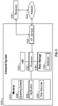
- the control module 40 of FIG. 1 may be implemented on one or more computer devices or systems, such as exemplary computer system 1030.
- the computer system 1030 includes a processor 1032, a memory 1034, a mass storage memory device 1036, an input/output (I/O) interface 1038, and a Human Machine Interface (HMI) 1040.
- the computer system 1030 is operatively coupled to one or more external resources 1042 via the network 1026 or I/O interface 1038.
- External resources may include, but are not limited to, servers, databases, mass storage devices, peripheral devices, cloud-based network services, or any other suitable computer resource that may be used by the computer system 1030.
- the processor 1032 includes one or more devices selected from microprocessors, microcontrollers, digital signal processors, microcomputers, central processing units, field programmable gate arrays, programmable logic devices, state machines, logic circuits, analog circuits, digital circuits, or any other devices that manipulate signals (analog or digital) based on operational instructions that are stored in the memory 1034.
- Memory 1034 includes a single memory device or a plurality of memory devices including, but not limited to, read-only memory (ROM), random access memory (RAM), volatile memory, non-volatile memory, static random-access memory (SRAM), dynamic random-access memory (DRAM), flash memory, cache memory, or any other device capable of storing information.
- the mass storage memory device 1036 includes data storage devices such as a hard drive, optical drive, tape drive, volatile or non-volatile solid-state device, or any other device capable of storing information.
- the processor 1032 operates under the control of an operating system 1046 that resides in memory 1034.
- the operating system 1046 manages computer resources so that computer program code embodied as one or more computer software applications, such as an application 1048 residing in memory 1034, may have instructions executed by the processor 1032.
- the processor 1032 may execute the application 1048 directly, in which case the operating system 1046 may be omitted.
- One or more data structures 1049 also reside in memory 1034, and may be used by the processor 1032, operating system 1046, or application 1048 to store or manipulate data.
- the I/O interface 1038 provides a machine interface that operatively couples the processor 1032 to other devices and systems, such as the network 1026 or external resource 1042.
- the application 1048 thereby works cooperatively with the network 1026 or external resource 1042 by communicating via the I/O interface 1038 to provide the various features, functions, applications, processes, or modules comprising examples of the disclosure.
- the application 1048 also includes program code that is executed by one or more external resources 1042, or otherwise rely on functions or signals provided by other system or network components external to the computer system 1030.
- examples of the disclosure may include applications that are located externally to the computer system 1030, distributed among multiple computers or other external resources 1042, or provided by computing resources (hardware and software) that are provided as a service over the network 1026, such as a cloud computing service.
- the HMI 1040 is operatively coupled to the processor 1032 of computer system 1030 in a known manner to allow a user to interact directly with the computer system 1030.
- the HMI 1040 may include video or alphanumeric displays, a touch screen, a speaker, and any other suitable audio and visual indicators capable of providing data to the user.
- the HMI 1040 also includes input devices and controls such as an alphanumeric keyboard, a pointing device, keypads, pushbuttons, control knobs, microphones, etc., capable of accepting commands or input from the user and transmitting the entered input to the processor 1032.
- a database 1044 may reside on the mass storage memory device 1036 and may be used to collect and organize data used by the various systems and modules described herein.
- the database 1044 may include data and supporting data structures that store and organize the data.
- the database 1044 may be arranged with any database organization or structure including, but not limited to, a relational database, a hierarchical database, a network database, or combinations thereof.
- a database management system in the form of a computer software application executing as instructions on the processor 1032 may be used to access the information or data stored in records of the database 1044 in response to a query, where a query may be dynamically determined and executed by the operating system 1046, other applications 1048, or one or more modules.
- a system (10) for refining a six degrees of freedom pose estimate (8) of a target object (12) based on a one-dimensional measurement comprises: a camera (42) configured to capture image data of the target object (12); a range-sensing device (44) configured to determine an actual distance (d) measured between the range-sensing device (44) and an actual point of intersection (W'), wherein the range-sensing device (44) projects a line-of-sight (L) that intersects with the target object (12) at the actual point of intersection (W'); one or more processors (e.g.
- one or more computer processors in electronic communication with the camera (42) and the range-sensing device (44); and a memory (1034) coupled to the one or more processors (1032), the memory (1034) storing data into one or more databases (1044) and program code that, when executed by the one or more processors (1032), causes the system (10) to: predict (206), based on the image data of the target object (12), the six degrees of freedom pose estimate (8) of the target object (12); determine (208) an estimated point of intersection (W) representing where the line-of-sight (L) intersects with the six degrees of freedom pose estimate (8) of the target object (12); determine (210) an estimated distance (D) measured between the range-sensing device (44) and the estimated point of intersection (W); calculate (212) an absolute error associated with the six degrees of freedom pose estimate (8) of the target object (12) based on a difference between the actual distance (d) and the estimated distance (D); and calculate (216) a revised six degrees of freedom pose estimate of the target object (12) based on at
- the one or more processors (1032) execute instructions to: calculate (214) a minimum value of the absolute error; and calculate (216) the revised six degrees of freedom pose estimate, wherein the revised six degree of freedom pose estimate produces the minimum value of the absolute error.
- the one or more processors (1032) execute instructions to: determine (218) a reprojection error introduced by the six degrees of freedom pose estimate (8) of the target object (12); determine (220) a minimum value of a weighted sum, wherein the weighted sum combines the absolute error and the reprojection error together; and calculate (222) the revised six degrees of freedom pose estimate, wherein the revised six degree of freedom pose estimate produces the minimum value of the weighted sum.
- the one or more processors (1032) determine the minimum value of the weighted sum based on a non-linear least square algorithm.
- the one or more processors (1032) execute instructions to: determine the six degrees of freedom pose estimate (8) of the target object (12) based on a perspective-n-point algorithm.
- the one or more processors (1032) execute instructions to: detect (252) a plurality of three-dimensional keypoints (62) that correspond to the target object (12) based on the image data captured by the camera (42); predict (254), by a deep neural network, a corresponding two-dimensional keypoint (60) for each of the plurality of three-dimensional keypoints (62); align (256) the plurality of three-dimensional keypoints (62) with a plurality of two-dimensional keypoints (62); and predict (258) the six degrees of freedom pose estimate (8) based on the three-dimensional keypoints (62).
- the one or more processors (1032) execute instructions to: determine (260) a plurality of two-dimensional pixel positions by projecting the plurality of three-dimensional keypoints (62) into two-dimensional space; and determine (262) a difference between a plurality of two-dimensional pixel positions and the plurality of two-dimensional keypoints (60), wherein the difference between the plurality of two-dimensional pixel positions and the plurality of two-dimensional keypoints (60) represent a reprojection error.
- system (10) of any of the seven preceding paragraphs further comprises an extendable arm (38) defining a longitudinal axis, wherein the longitudinal axis of the extendable arm (38) is aligned with the line-of-sight (L) of the range-sensing device (44).
- the extendable arm (38) is a boom assembly (20) of an aerial refueling system (14) or a robotic arm.
- the range-sensing device (44) is mounted statically to the extendable arm (38).
- the one or more processors (1032) execute instructions to: in response to determining the revised six degrees of freedom pose estimate, determine (224) a position and an orientation of the extendable arm (38) based on the revised six degrees of freedom pose estimate.
- the range-sensing device (44) is a laser range finder, an ultrasonic sensor, an infrared distance sensor, a light detection and ranging distance (lidar) sensor, or a sonar sensor.
- the actual distance (d) represents a one-dimensional depth measurement between the range-sensing device (44) and the target object (12).
- an aerial refueling system (14) for a supply aircraft (18), the aerial refueling system (14) comprises: a boom assembly (20) including a nozzle (30); and a system (10) for determining a revised six degrees of freedom pose estimate of a fuel receptacle (32) located on a receiver aircraft (34), wherein the nozzle (30) of the boom assembly (20) is configured to engage with a fuel receptacle (32) of the receiver aircraft (34) during a refueling operation, the system (10) comprising: a camera (42) configured to capture (202) image data of the receiver aircraft (34) and the fuel receptacle (32); a range-sensing device (44) configured to determine (204) an actual distance (d) measured between the range-sensing device (44) and an actual point of intersection (W'), wherein the range-sensing device (44) projects a line-of-sight (L) that intersects with the receiver aircraft at the actual point of intersection (W'); one or more processor
- the one or more processors (1032) execute instructions to: calculate (214) a minimum value of the absolute error; and calculate (216) the revised six degrees of freedom pose estimate, wherein the revised six degree of freedom pose estimate produces the minimum value of the absolute error.
- the one or more processors (1032) execute instructions to: determine (218) a reprojection error introduced by the six degrees of freedom pose estimate (8) of the fuel receptacle (32) located on the receiver aircraft (34); determine (220) a minimum value of a weighted sum, wherein the weighted sum combines the absolute error and the reprojection error together; and calculate (222) the revised six degrees of freedom pose estimate, wherein the revised six degree of freedom pose estimate produces the minimum value of the weighted sum.
- a method (200) for refining a six degrees of freedom pose estimate (8) of a target object (12) comprises: capturing (202), by a camera (42), image data of the target object (12); determining (204), by a range-sensing device (44), an actual distance (d) measured between the range-sensing device (44) and an actual point of intersection (W'), wherein the range-sensing device (44) projects a line-of-sight (L) that intersects with the target object (12) at the actual point of intersection (W'); predicting (206), based on the image data of the target object (12), the six degrees of freedom pose estimate (8) of the target object (12); determining (208) an estimated point of intersection (W) representing where the line-of-sight (L) intersects with the six degrees of freedom pose estimate (8) of the target object (12); determining (210) an estimated distance (D) measured between the range-sensing device (44) and the estimated point of intersection (
- the method of the preceding paragraph further comprises: calculating (214) a minimum value of the absolute error; and calculating (216) the revised six degrees of freedom pose estimate, wherein the revised six degree of freedom pose estimate produces the minimum value of the absolute error.
- the method of either of the two preceding paragraphs further comprises: determining (218) a reprojection error introduced by the six degrees of freedom pose estimate (8) of the target object (12); determining (220) a minimum value of a weighted sum, wherein the weighted sum combines the absolute error and the reprojection error together; and calculating (222) the revised six degrees of freedom pose estimate, wherein the revised six degree of freedom pose estimate produces the minimum value of the weighted sum.
- the six degrees of freedom pose estimate (8) of the target object (12) is determined based on a perspective-n-point algorithm.
Landscapes
- Engineering & Computer Science (AREA)
- Physics & Mathematics (AREA)
- Remote Sensing (AREA)
- Radar, Positioning & Navigation (AREA)
- General Physics & Mathematics (AREA)
- Theoretical Computer Science (AREA)
- Computer Vision & Pattern Recognition (AREA)
- Computer Networks & Wireless Communication (AREA)
- Electromagnetism (AREA)
- Aviation & Aerospace Engineering (AREA)
- Multimedia (AREA)
- Automation & Control Theory (AREA)
- Acoustics & Sound (AREA)
- Length Measuring Devices By Optical Means (AREA)
- Length Measuring Devices With Unspecified Measuring Means (AREA)
Abstract
Description
- The present disclosure relates to a system and method of refining a six degrees of freedom pose estimate of a target object. More particularly, the present disclosure is directed towards a system and method of refining a six degrees of freedom pose estimate of the target object based on a single one-dimensional measurement.
- Six degrees of freedom (6DOF) refers to the freedom of movement of a rigid body in three-dimensional space. Specifically, the rigid body may move in three dimensions, on the x, y and z axes, as well as change orientation between the three axes though rotation, which are referred to as pitch, roll, and yaw.
- Image-based pose estimation systems may estimate a six degrees of freedom pose of an object. Furthermore, many image-based pose estimation systems also utilize some type of refinement process for revising an initial six degrees of freedom pose estimate. Some types of pose estimate refinement processes utilize a three-dimension depth map or, in the alternative, numerous two-dimension distance measurements where a laser range finder is used to take the two-dimensional distance measurements. However, both the three-dimensional depth map and the two-dimensional distance measurements typically require significant processing and memory allocation requirements. Moreover, the laser range finder used in the two-dimensional distance measurement approach may require precisely manufactured moving parts in order to maintain consistent two-dimensional distance measurements, which in turn adds cost to the system. Additionally, some types of pose estimate refinement approaches may require specialized calibration patterns or correspondence markers for registering the scan lines of the laser range finder with corresponding features that are part of a model.
- A system for refining a six degrees of freedom pose estimate of a target object based on a one-dimensional measurement is disclosed. The system includes a camera configured to capture image data of the target object and a range-sensing device configured to determine an actual distance measured between the range-sensing device and an actual point of intersection. The range-sensing device projects a line-of-sight that intersects with the target object at the actual point of intersection. The system also includes one or more processors in electronic communication with the camera and the range-sensing device as well as a memory coupled to the one or more processors. The memory stores data into one or more databases and program code that, when executed by the one or more processors, causes the system to predict, based on the image data of the target object, the six degrees of freedom pose estimate of the target object. The system determines an estimated point of intersection representing where the line-of-sight intersects with the six degrees of freedom pose estimate of the target object. The system also determines an estimated distance measured between the range-sensing device and the estimated point of intersection. The system calculates an absolute error associated with the six degrees of freedom pose estimate of the target object based on a difference between the actual distance and the estimated distance. The system then determines a revised six degrees of freedom pose estimate of the target object based on at least the absolute error.
- An aerial refueling system for a supply aircraft is disclosed. The aerial refueling system includes a boom assembly including a nozzle and a system for determining a revised six degrees of freedom pose estimate of a fuel receptacle located on a receiver aircraft. The nozzle of the boom assembly is configured to engage with a fuel receptacle of the receiver aircraft during a refueling operation. The system includes a camera configured to capture image data of the receiver aircraft and the fuel receptacle and a range-sensing device configured to determine an actual distance measured between the range-sensing device and an actual point of intersection. The range-sensing device projects a line-of-sight that intersects with the receiver aircraft at the actual point of intersection. The system also includes one or more processors in electronic communication with the camera and the range-sensing device and a memory coupled to the one or more processors. The memory stores data into one or more databases and program code that, when executed by the one or more processors, causes the system to predict, based on the image data of the fuel receptacle located on a receiver aircraft, the six degrees of freedom pose estimate of the fuel receptacle located on the receiver aircraft. The system determines an estimated point of intersection representing where the line-of-sight intersects with the six degrees of freedom pose estimate of the receiver aircraft. The system determines an estimated distance measured between the range-sensing device and the estimated point of intersection. The system calculates an absolute error associated with the six degrees of freedom pose estimate of the fuel receptacle located on the receiver aircraft based on a difference between the actual distance and the estimated distance. The system then determines a revised six degrees of freedom pose estimate based on at least the absolute error.
- A method for refining a six degrees of freedom pose estimate of a target object is disclosed. The method includes capturing, by a camera, image data of the target object. The method also includes determining, by a range-sensing device, an actual distance measured between the range-sensing device and an actual point of intersection, where the range-sensing device projects a line-of-sight that intersects with the target object at the actual point of intersection. The method also includes predicting, based on the image data of the target object, the six degrees of freedom pose estimate of the target object. The method further includes determining an estimated point of intersection representing where the line-of-sight intersects with the six degrees of freedom pose estimate of the target object. The method further includes determining an estimated distance measured between the range-sensing device and the estimated point of intersection. The method also includes calculating an absolute error associated with the six degrees of freedom pose estimate of the target object based on a difference between the actual distance and the estimated distance. Finally, the method includes determining a revised six degree of freedom pose estimate based on at least the absolute error.
- The features, functions, and advantages that have been discussed may be achieved independently in various examples or may be combined in other examples further details of which can be seen with reference to the following description and drawings.
- The drawings described herein are for illustration purposes only and are not intended to limit the scope of the present disclosure in any way.
-
FIG. 1 is an illustration of the disclosed system for refining a six degrees of freedom pose estimate of a target object, where the system is located upon a supply aircraft and the target object is a fuel receptacle of a receiver aircraft; -
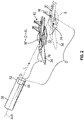
FIG. 2 is a diagram illustrating an extending arm, the receiver aircraft, and the six degrees of freedom pose estimate of the supply aircraft; -
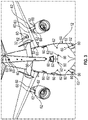
FIG. 3 is an illustration of an exemplary approach for determining the six degrees of freedom pose estimate of a target object based on a plurality of two-dimensional keypoints and a plurality of three-dimensional keypoints; -
FIGS. 4A-4B are a process flow diagram illustrating a method for refining a six degrees of freedom pose estimate of the target object; -
FIG. 4C is a process flow diagram illustrating a method for determining the reprojection error; and -
FIG. 5 is an illustration of a computer system for the disclosed system shown inFIG. 1 . - The present disclosure relates to a system and method of refining a six degrees of freedom pose estimate of a target object based on a single one-dimensional measurement. The system includes a control module in electronic communication with a camera and a range-sensing device. The camera is configured to capture image data of the target object, and the range-sensing device is configured to determine the one-dimensional measurement. The range-sensing device determines an actual distance measured between the range-sensing device and an actual point of intersection W'. Specifically, the actual point of intersection W' represents where a line-of-sight projected by the range-sensing device intersects with the target object. The system determines the six degrees of freedom pose estimate of the target object based on the image data captured by the camera. The system then determines an estimated point of intersection representing where the line-of-sight intersects with the six degrees of freedom pose estimate of the target object. The system then determines an estimated distance measured between the range-sensing device and the estimated point of intersection. The system calculates an absolute error based on a difference between the actual distance and the estimated distance. In some examples, the system also determines a reprojection error introduced by the six degrees of freedom pose estimate of the target object. The system then determines a revised pose estimate of the target object based on the absolute error and, if available, the reprojection error.
- The following description is merely exemplary in nature and is not intended to limit the present disclosure, application, or uses.
- Referring to
FIG. 1 , asystem 10 for refining a six degrees of freedom pose estimate 8 (seen inFIG. 2 ) of atarget object 12 is illustrated. In this and other examples, thesystem 10 is part of anaerial refueling system 14 located at atail section 16 of a tanker orsupply aircraft 18. Theaerial refueling system 14 includes aboom assembly 20 connected to afuselage 22 of thesupply aircraft 18 at an articulating joint 24. Theboom assembly 20 includes arigid portion 26, atelescoping extension 28, and anozzle 30. Thenozzle 30 of theboom assembly 20 is engaged with afuel receptacle 32 of areceiver aircraft 34 during a refueling operation. In this and other examples, thereceiver aircraft 34, and in particular thefuel receptacle 32, represent thetarget object 12. Accordingly, thesystem 10 refines the six degrees of freedom pose estimate 8 (FIG. 2 ) of thefuel receptacle 32 and thereceiver aircraft 34. Thesystem 10 includes acontrol module 40 in electronic communication with acamera 42 and a range-sensingdevice 44. Thecamera 42 is positioned in a location to capture image data of the target object 12 (i.e., thefuel receptacle 32 and the receiver aircraft 34). Thecontrol module 40 predicts the six-degree of freedom pose estimate 8 of thetarget object 12 based on the image data captured by thecamera 42. - Referring to both
FIGS. 1 and2 , the range-sensingdevice 44 is configured to determine an actual distance d between the range-sensing device 44 (shown inFIG. 2 ) and the target object 12 (i.e., the fuel receptacle 32). The actual distance d represents a single one-dimensional measurement determined by the range-sensingdevice 44. As explained below, thecontrol module 40 of thesystem 10 determines an absolute error associated with the six degrees of freedom pose estimate 8 of thetarget object 12 based on the actual distance d. In some examples, thecontrol module 40 determines a revised six degrees of freedom pose estimate of thetarget object 12 based on the absolute error. As explained also below, in other examples thecontrol module 40 also determines a reprojection error associated with estimating the six degrees of freedom pose estimate 8, and then determines the revised six degrees of freedom pose estimate based on both the reprojection error and the absolute error. - In some examples, including the example as shown in
FIG. 1 , thecontrol module 40 determines a position and an orientation of theboom assembly 20 based on the revised six degrees of freedom pose estimate. However, it is to be appreciated thatFIG. 1 is merely exemplary in nature and thesystem 10 is not limited to theaerial refueling system 14. Indeed, thesystem 10 may be used in a variety of other applications where a six degrees of freedom pose estimate of a rigid object is estimated. As seen inFIG. 2 , thesystem 10 includes an extendable arm 38. The extendable arm 38 is represented by theboom assembly 20 shown inFIG. 1 , however, it is to be appreciated that the extendable arm 38 is not limited to theboom assembly 20. In some examples, the extendable arm 38 is a robotic arm that grasps and manipulates objects. In some examples including this example, thecontrol module 40 determines a position and an orientation of the extendable arm 38 based on the revised six degrees of freedom pose estimate as the extendable arm 38 grasps and manipulates an object. - The
camera 42 sends a video or image feed to thecontrol module 40. In some examples including the example as shown inFIG. 1 , thecamera 42 is mounted to anunderside 46 of thefuselage 22 of thesupply aircraft 18. However, it is to be appreciated that the position of thecamera 42 is not limited to any specific location on thereceiver aircraft 34. Instead, thecamera 42 is positioned in any location where a field-of-view 50 of thecamera 42 captures thetarget object 12. For example, thecamera 42 may be mounted along any number of locations along theunderside 46 of thefuselage 22 of thesupply aircraft 18 as long as the field-of-view 50 of thecamera 42 captures thefuel receptacle 32 and thereceiver aircraft 34, as shown inFIG. 1 . - The range-sensing
device 44 is any type of device for determining a distance to a specific target location without the need for physical contact. The range-sensingdevice 44 includes, but is not limited to, a laser range finder, an ultrasonic sensor, an infrared distance sensor, a light detection and ranging distance (lidar) sensor, or a sonar sensor. In some examples like the the non-limiting example as shown inFIGS. 1 , the range-sensingdevice 44 is mounted statically to adistal end 48 of therigid portion 26 of theboom assembly 20. In some examples including the example as seen inFIG. 2 , the range-sensingdevice 44 is also mounted to adistal end 52 of the extendable arm 38. As seen in bothFIGS. 1 and2 , the line-of-sight L of the range-sensingdevice 44 is aligned with a longitudinal axis A-A of the extendable arm 38 (or the boom assembly 20). Accordingly, thecontrol module 40 determines the position and the line-of-sight L of the range-sensingdevice 44 based on the movement of the extendable arm 38. For example, if the extendable arm 38 is a robotic arm, then thecontrol module 40 determines the position and the line-of-sight L based on the robotic arm's joint angles. - It is to be appreciated that the range-sensing
device 44 may be located in a variety of locations other than therigid portion 26 of theboom assembly 20 as seem inFIG. 1 or on the extendable arm 38 as seen inFIG. 2 . In other words, the line-of-sight L of the range-sensingdevice 44 may not be aligned with the longitudinal axis A-A of the extendable arm 38. Instead, the range-sensingdevice 44 is positioned in any location where the line-of-sight L of the range-sensingdevice 44 intersects with thetarget object 12. In some alternative examples, the range-sensingdevice 44 is mounted directly adjacent to thecamera 42 on theunderside 46 of thefuselage 22 of thesupply aircraft 18. - Referring to
FIGS. 1 and2 , the position, orientation, and intrinsic parameters of thecamera 42 are determined in a preliminary off-line camera calibration procedure or, alternatively, the intrinsic parameters are saved in a memory 1034 (FIG. 5 ) of thecontrol module 40. Some examples of the intrinsic parameters of thecamera 42 include, but are not limited to, resolution and aspect ratio. A three-dimensional representation 54 of thetarget object 12 is shown in phantom line inFIG. 2 . The three-dimensional representation 54 is also saved in thememory 1034 of thecontrol module 40 as well. Thecontrol module 40 is configured to predict the six degrees of freedom pose estimate 8 of the target object 12 (i.e., thefuel receptacle 32 and the receiver aircraft 34) based on the image data captured by thecamera 42 using any number of pose estimation approaches. In some examples, thecontrol module 40 determines the six-degree of freedom pose estimate 8 of thetarget object 12 based on a perspective-n-point algorithm. - Referring to both
FIGS. 1 and3 , the perspective-n-point algorithm estimates the six degrees of freedom pose estimate 8 (FIG. 2 ) of thetarget object 12 based on a plurality of two-dimensional keypoints 60 and a plurality of three-dimensional keypoints 62 (the two-dimensional keypoints 60 are shown as circles and the three-dimensional keypoints 62 are shown as crosses). Specifically, the perspective-n-point algorithm requires three or more three-dimensional keypoints 62 disposed on thetarget object 12. The three-dimensional keypoints 62 are detected by thecontrol module 40 based on the image data captured by thecamera 42. Thecontrol module 40 detects the three or more three-dimensional keypoints 62 on the target object 12 (i.e., the fuel receptacle 32) in each image frame of the image feed received from thecamera 42. Thecontrol module 40 then predicts a corresponding two-dimensional keypoint 60 for each of the plurality of three-dimensional keypoints 62 using a deep neural network. Thecontrol module 40 then aligns the plurality of three-dimensional keypoints 62 with the corresponding two-dimensional keypoints 60, and then predicts the six degrees of freedom pose estimate based on the three-dimensional keypoints 62. - It is to be appreciated that while a perspective-n-point algorithm is described, other pose estimation processes may also be used to determine the six degrees of freedom pose estimate. For example, in an alternative approach, the six degrees of freedom pose estimate is determined based on two or more point-tangent correspondences between the three-
dimensional keypoints 62 and the two-dimensional keypoints 60. In other examples, the six degrees of freedom pose estimate is determined by deep neural network that determines the six degrees of freedom pose estimate directly based on the image data captured by thecamera 42. - Referring back to
FIGS. 1 and2 , once thecontrol module 40 determines the six degrees of freedom pose estimate 8, thecontrol module 40 then aligns the longitudinal axis A-A of the extendable arm 38 in a direction towards the target object 12 (i.e., the receiver aircraft 34). It is to be appreciated that the initial six degrees of freedom pose estimate 8 as described above may be a locally coarse estimate, and the longitudinal axis A-A of the extendable arm 38 (and therefore the line-of sight L of the range-sensing device 44) only needs to generally intersect with the target object 12 (i.e., the receiver aircraft 34). In some examples including the example as shown inFIGS. 1 and2 , since thenozzle 30 of theboom assembly 20 engages with thefuel receptacle 32 of thereceiver aircraft 34 during a refueling operation, the range-sensingdevice 44 projects the line-of-sight L towards thefuel receptacle 32. - The range-sensing
device 44 is configured to determine the actual distance d. Referring specifically toFIG. 2 , the actual distance d is measured between the range-sensingdevice 44 and an actual point of intersection W'. The line-of-sight L projected by the range-sensingdevice 44 intersects with the target object 12 (i.e., the fuel receptacle 32) at the actual point of intersection W'. Thus, the actual distance d represents a one-dimensional depth measurement between the range-sensingdevice 44 and thetarget object 12. It is to be appreciated that prior to the pose refinement process using the range-sensingdevice 44, depth estimates, such as estimates of the distance d, are associated with the greatest amount of error when compared to length and height measurements. This is because the initial six degrees of freedom pose estimate is based on a perspective of thecamera 42, which lacks depth cues. Furthermore, it is also to be appreciated that the position of the actual point of intersection W' upon asurface 70 of thereceiver aircraft 34 need not be known. Finally, it is also to be appreciated that the actual point of intersection W' may lie anywhere upon thesurface 70 of thereceiver aircraft 34. - Referring specifically to
FIG. 2 , thecontrol module 40 then determines an estimated point of intersection W. The estimated point of intersection W represents where the line-of-sight L intersects with the six degrees of freedom pose estimate 8 of thetarget object 12. As seen inFIG. 2 , the estimated point of intersection W is offset from the actual point of intersection W' because of the coarseness of the initial six degrees of freedom pose estimate 8. Thecontrol module 40 then determines an estimated distance D measured between the range-sensingdevice 44 and the estimated point of intersection W. Thecontrol module 40 then calculates the absolute error associated with the six degrees of freedom pose estimate 8 of thetarget object 12 based on a difference between the actual distance d and the estimated distance D. Specifically, the absolute error is expressed in Equation 1 as:
FIG. 2 , and W'=(O + dL). In other words, Equation 1 may be expressed as ||W - W'||2. - In addition to the absolute error, in some examples, the
control module 40 also determines the reprojection error introduced by the six degrees of freedom pose estimate 8. Specifically, the reprojection error represents a difference between a plurality of two-dimensional pixel positions and the plurality of two-dimensional keypoints 60 shown inFIG. 3 . The plurality of two-dimensional pixel positions are determined by projecting the three-dimensional keypoints 62 (FIG. 2 ) into two-dimensional space. It is to be appreciated that the three-dimensional keypoints 62 shown inFIG. 3 are represented in camera space. The camera space refers to a three-dimensional coordinate system having an origin represented by a center C of the camera 42 (FIG. 1 ), where a user defines the three axes (i.e., x, y, and z). Thus, the three-dimensional keypoints 62 indicate how thetarget object 12 appears with respect to the perspective view of thecamera 42. For example, if thetarget object 12 is located 20 meters straight in front of thecamera 42, then a z-coordinate (which is assumed to be aligned with a line-of-sight of the camera 42) of the resulting three-dimensional keypoint 62 would be 20 meters. It is also to be appreciated that when the three-dimensional keypoints 62 are projected into the two-dimensional space to represent the two-dimensional pixel locations, the three-dimensional keypoints 62 are flattened along a depth dimension. However, the range-sensingdevice 44 is aligned (or substantially aligned) with the depth dimension, and therefore adds information that is otherwise missing from the two-dimensional pixel locations. - The reprojection error of the perspective-n-point algorithm is expressed in Equation 2 as:

camera 42, V represents a coordinate transform matrix, R represents a rotation matrix representing the three orientation components (pitch, roll, and yaw) of the six degrees of freedom parameters, X represents a matrix containing the plurality of three-dimensional keypoints 62, t represents a vector representing the positional components (x, y, and z), of the six degrees of freedom parameters, and y' represents the two-dimensional keypoints 60 (shown inFIG. 3 ). The camera projection function of thecamera 42 converts the three-dimensional keypoints 62, which are represented by the camera space, into the two-dimensional dimensional space. The coordinate transform matrix V converts the three-dimensional keypoints 62 represented in model space into the camera space. The model space represents a three-dimensional coordinate system having an origin 74 (seen inFIG. 2 ) that is located at a center of the three-dimensional representation 54. The vector t contains the positional components of the six degrees of freedom parameters and defines the translation betweenorigin 74 of the model space and the center C of the camera space. Similarly, the rotation matrix R contains the orientation components of the six degrees of freedom parameters and defines the rotation between the axes defined in model space and the axes defined in camera space. - In some examples, the
control module 40 determines the revised six degrees of freedom pose estimate based on just the absolute error. In these and other examples, thecontrol module 40 determines a minimum value of the absolute error, and then calculates the revised six degrees of freedom pose estimate produces or results in the minimum value of the absolute error. In other words,control module 40 determines a value for the refined six degrees of freedom pose estimate associated with the least amount of absolute error. The minimum value of the absolute error is expressed in Equation 3 as:
target object 12, i.e., θ = [x, y, z, pitch, roll, yaw]. - In other examples, the
control module 40 determines the revised six degrees of freedom pose estimate 8 based on both the absolute error and the reprojection error. In some examples, thecontrol module 40 determines the revised six degrees of freedom pose estimate by first determining a minimum value of a weighted sum, where the weighted sum combines the absolute error and the reprojection error together. The weighted sum is expressed in Equation 4 as:
device 44 and the six degree of freedom pose estimate 8. The minimum value of the weighted sum is determined based on a non-linear least square algorithm. There are several types of non-linear least square algorithms available that may be used to determine the minimum value of the weighted sum. Some examples of non-linear least square algorithms include, but are not limited to, Gauss-Newton methods, a Levenberg-Marquardt algorithm, a gradient method such as a conjugate-gradient method, and direct search methods such as a Nelder-Mead simplex search. -
FIGS. 4A-4B is an exemplary process flow diagram illustrating amethod 200 for refining the six degrees of freedom pose estimate 8 (FIG. 2 ) of thetarget object 12. Referring generally toFIGS. 1-4A , themethod 200 begins atblock 202. Inblock 202, thecamera 42 captures the image data of thetarget object 12. Themethod 200 may then proceed to block 204. - In
block 204, the range-sensingdevice 44 determines the actual distance d. As mentioned above, the actual distance d is measured between the range-sensingdevice 44 and the actual point of intersection W' (seen inFIG. 2 ), where the range-sensingdevice 44 projects the line-of-sight L that intersects with thetarget object 12 at the actual point of intersection W'. Themethod 200 may then proceed to block 206. - In
block 206, thecontrol module 40 predicts, based on the image data of thetarget object 12, the six degrees of freedom pose estimate 8 of thetarget object 12. As explained above, the six degrees of freedom pose estimate 8 may be determined using any number of pose estimation approaches such as, for example, the perspective-n-point algorithm. Themethod 200 may then proceed to block 208. - In
block 208, thecontrol module 40 determines the estimated point of intersection W (FIG. 2 ) representing where the line-of-sight L intersects with the six degrees of freedom pose estimate 8 of thetarget object 12. Themethod 200 may then proceed to block 210. - In
block 210, thecontrol module 40 determines the estimated distance D measured between the range-sensingdevice 44 and the estimated point of intersection W. Themethod 200 may then proceed to block 212. - In
block 212, thecontrol module 40 calculates the absolute error associated with the six degrees of freedom pose estimate 8 of thetarget object 12 based on a difference between the actual distance and the estimated distance. Themethod 200 may then proceed todecision block 214. - In
decision block 214, the revised six degree of freedom estimate is determined based on either the absolute error alone or, in the alternative, based on the absolute error and the reprojection error. If thecontrol module 40 determines the revised six degree of freedom pose estimate is determined based on the absolute error alone, then the method proceeds to block 216. - In
block 216, thecontrol module 40 calculates the minimum value of the absolute error. As explained above, thecontrol module 40 calculates the absolute error associated with the six degrees of freedom pose estimate 8 of thetarget object 12 based on a difference between the actual distance d and the estimated distance D and is expressed in Equation 1. Themethod 200 may then proceed to block 218. - In
block 218, thecontrol module 40 calculates the revised six degrees of freedom pose estimate, where the revised six degree of freedom pose estimate produces the minimum value of the absolute error. Themethod 200 may then terminate. - Referring back to decision block 214, if the revised six degrees of freedom pose estimate is not determined based on the absolute error alone, then the
method 200 proceeds to block 220, which is shown inFIG. 4B . Specifically, if thecontrol module 40 determines the revised six degree of freedom pose estimate based on both the absolute error and the reprojection error then themethod 200 proceeds to block 220. - In
block 220, thecontrol module 40 determines the reprojection error introduced by the six degrees of freedom pose estimate 8 of thetarget object 12. As explained above, the reprojection error represents the difference between the plurality of two-dimensional pixel positions and the plurality of two-dimensional keypoints 60 shown inFIG. 3 . It is to be appreciated that a process flow diagram for determining the reprojection error is shown inFIG. 4C . Themethod 200 may then proceed to block 222. - In
block 222, thecontrol module 40 determines the minimum value of the weighted sum, where the weighted sum combines the absolute error and the reprojection error together. The minimum value of the weighted sum may be determined using a variety of different approaches such as, for example, the Levenberg-Marquardt algorithm. Themethod 200 may then proceed to block 224. - In
block 224, thecontrol module 40 calculates the revised six degrees of freedom pose estimate, where the revised six degrees of freedom pose estimate produces the minimum value of the weighted sum. In some examples, themethod 200 may then proceed to block 226. - In
block 226, in some examples, the disclosedsystem 10 includes the extendable arm 38 (seen inFIG. 1 as theboom assembly 20 and inFIG. 2 ). Accordingly, inblock 226, in response to determining the revised six degrees of freedom pose estimate, thecontrol module 40 determines a position and an orientation of the extendable arm 38 based on the revised six degrees of freedom pose estimate. Themethod 200 may then terminate. - Referring now to
FIG. 4C , a process flow diagram illustrating amethod 250 for determining the reprojection error is now described. Referring toFIGS. 1 ,3 , and4C , themethod 250 begins atblock 252. Inblock 252, thecontrol module 40 detects the plurality of three-dimensional keypoints 62 that correspond to thetarget object 12 based on the image data captured by thecamera 42. Themethod 250 may then proceed to block 254. - The
block 254, a deep neural network predicts the corresponding two-dimensional keypoint 60 for each of the plurality of three-dimensional keypoints 62. Themethod 250 may then proceed to block 256. - In
block 256, thecontrol module 40 aligns the plurality of three-dimensional keypoints 62 with the plurality of two-dimensional keypoints 60. Themethod 250 may then proceed to block 258. - In
block 258, thecontrol module 40 predicts the six degrees of freedom pose estimate 8 based on the three-dimensional keypoints 62. Themethod 250 may then proceed to block 260. - In
block 260, thecontrol module 40 determines the plurality of two-dimensional pixel positions by projecting the plurality of three-dimensional keypoints 62 into two-dimensional space. Themethod 250 may then proceed to block 262. - In
block 262, thecontrol module 40 determines the difference between a plurality of two-dimensional pixel positions and the plurality of two-dimensional keypoints 60, where the difference between the plurality of two-dimensional pixel positions and the plurality of two-dimensional keypoints 60 represent the reprojection error. Themethod 250 may then terminate. - Referring generally to the figures, the disclosed system provides various technical effects and benefits. Specifically, the disclosed system utilizes a single one-dimensional measurement from the range-sensing device for refining the six degrees of freedom pose estimate as opposed to a two-dimensional scan or, alternatively, a three-dimensional depth map. Accordingly, the disclosed system does not require significant processing and memory allocation requirements or a laser range finder having precisely manufactured moving parts like some conventional systems currently available. Additionally, the disclosed system does not require specialized calibration patterns or correspondence markers during the refinement process, unlike some conventional systems currently available as well.
- Referring to
FIG. 5 , thecontrol module 40 ofFIG. 1 may be implemented on one or more computer devices or systems, such asexemplary computer system 1030. Thecomputer system 1030 includes aprocessor 1032, amemory 1034, a massstorage memory device 1036, an input/output (I/O)interface 1038, and a Human Machine Interface (HMI) 1040. Thecomputer system 1030 is operatively coupled to one or moreexternal resources 1042 via thenetwork 1026 or I/O interface 1038. External resources may include, but are not limited to, servers, databases, mass storage devices, peripheral devices, cloud-based network services, or any other suitable computer resource that may be used by thecomputer system 1030. - The
processor 1032 includes one or more devices selected from microprocessors, microcontrollers, digital signal processors, microcomputers, central processing units, field programmable gate arrays, programmable logic devices, state machines, logic circuits, analog circuits, digital circuits, or any other devices that manipulate signals (analog or digital) based on operational instructions that are stored in thememory 1034.Memory 1034 includes a single memory device or a plurality of memory devices including, but not limited to, read-only memory (ROM), random access memory (RAM), volatile memory, non-volatile memory, static random-access memory (SRAM), dynamic random-access memory (DRAM), flash memory, cache memory, or any other device capable of storing information. The massstorage memory device 1036 includes data storage devices such as a hard drive, optical drive, tape drive, volatile or non-volatile solid-state device, or any other device capable of storing information. - The
processor 1032 operates under the control of anoperating system 1046 that resides inmemory 1034. Theoperating system 1046 manages computer resources so that computer program code embodied as one or more computer software applications, such as anapplication 1048 residing inmemory 1034, may have instructions executed by theprocessor 1032. In some alternative examples, theprocessor 1032 may execute theapplication 1048 directly, in which case theoperating system 1046 may be omitted. One ormore data structures 1049 also reside inmemory 1034, and may be used by theprocessor 1032,operating system 1046, orapplication 1048 to store or manipulate data. - The I/
O interface 1038 provides a machine interface that operatively couples theprocessor 1032 to other devices and systems, such as thenetwork 1026 orexternal resource 1042. Theapplication 1048 thereby works cooperatively with thenetwork 1026 orexternal resource 1042 by communicating via the I/O interface 1038 to provide the various features, functions, applications, processes, or modules comprising examples of the disclosure. Theapplication 1048 also includes program code that is executed by one or moreexternal resources 1042, or otherwise rely on functions or signals provided by other system or network components external to thecomputer system 1030. Indeed, given the nearly endless hardware and software configurations possible, persons having ordinary skill in the art will understand that examples of the disclosure may include applications that are located externally to thecomputer system 1030, distributed among multiple computers or otherexternal resources 1042, or provided by computing resources (hardware and software) that are provided as a service over thenetwork 1026, such as a cloud computing service. - The
HMI 1040 is operatively coupled to theprocessor 1032 ofcomputer system 1030 in a known manner to allow a user to interact directly with thecomputer system 1030. TheHMI 1040 may include video or alphanumeric displays, a touch screen, a speaker, and any other suitable audio and visual indicators capable of providing data to the user. TheHMI 1040 also includes input devices and controls such as an alphanumeric keyboard, a pointing device, keypads, pushbuttons, control knobs, microphones, etc., capable of accepting commands or input from the user and transmitting the entered input to theprocessor 1032. - A
database 1044 may reside on the massstorage memory device 1036 and may be used to collect and organize data used by the various systems and modules described herein. Thedatabase 1044 may include data and supporting data structures that store and organize the data. In particular, thedatabase 1044 may be arranged with any database organization or structure including, but not limited to, a relational database, a hierarchical database, a network database, or combinations thereof. A database management system in the form of a computer software application executing as instructions on theprocessor 1032 may be used to access the information or data stored in records of thedatabase 1044 in response to a query, where a query may be dynamically determined and executed by theoperating system 1046,other applications 1048, or one or more modules. - Further illustrative and non-exclusive examples according to, the disclosure are described in the following paragraphs:
- In an example according to the present disclosure a system (10) for refining a six degrees of freedom pose estimate (8) of a target object (12) based on a one-dimensional measurement, the system (10) comprises: a camera (42) configured to capture image data of the target object (12); a range-sensing device (44) configured to determine an actual distance (d) measured between the range-sensing device (44) and an actual point of intersection (W'), wherein the range-sensing device (44) projects a line-of-sight (L) that intersects with the target object (12) at the actual point of intersection (W'); one or more processors (e.g. one or more computer processors), in electronic communication with the camera (42) and the range-sensing device (44); and a memory (1034) coupled to the one or more processors (1032), the memory (1034) storing data into one or more databases (1044) and program code that, when executed by the one or more processors (1032), causes the system (10) to: predict (206), based on the image data of the target object (12), the six degrees of freedom pose estimate (8) of the target object (12); determine (208) an estimated point of intersection (W) representing where the line-of-sight (L) intersects with the six degrees of freedom pose estimate (8) of the target object (12); determine (210) an estimated distance (D) measured between the range-sensing device (44) and the estimated point of intersection (W); calculate (212) an absolute error associated with the six degrees of freedom pose estimate (8) of the target object (12) based on a difference between the actual distance (d) and the estimated distance (D); and calculate (216) a revised six degrees of freedom pose estimate of the target object (12) based on at least the absolute error.
- Optionally, in the system (10) of the paragraph above, the one or more processors (1032) execute instructions to: calculate (214) a minimum value of the absolute error; and calculate (216) the revised six degrees of freedom pose estimate, wherein the revised six degree of freedom pose estimate produces the minimum value of the absolute error.
- Optionally, in the system (10) of either of the preceding two paragraphs, the one or more processors (1032) execute instructions to: determine (218) a reprojection error introduced by the six degrees of freedom pose estimate (8) of the target object (12); determine (220) a minimum value of a weighted sum, wherein the weighted sum combines the absolute error and the reprojection error together; and calculate (222) the revised six degrees of freedom pose estimate, wherein the revised six degree of freedom pose estimate produces the minimum value of the weighted sum.
- Optionally, in the system (10) of any of the three preceding paragraphs, the one or more processors (1032) determine the minimum value of the weighted sum based on a non-linear least square algorithm.
- Optionally, in the system (10) of any of the four preceding paragraphs, the one or more processors (1032) execute instructions to: determine the six degrees of freedom pose estimate (8) of the target object (12) based on a perspective-n-point algorithm.
- Optionally, in the system (10) of any of the five preceding paragraphs, the one or more processors (1032) execute instructions to: detect (252) a plurality of three-dimensional keypoints (62) that correspond to the target object (12) based on the image data captured by the camera (42); predict (254), by a deep neural network, a corresponding two-dimensional keypoint (60) for each of the plurality of three-dimensional keypoints (62); align (256) the plurality of three-dimensional keypoints (62) with a plurality of two-dimensional keypoints (62); and predict (258) the six degrees of freedom pose estimate (8) based on the three-dimensional keypoints (62).
- Optionally, in the system (10) of any of the six preceding paragraphs, the one or more processors (1032) execute instructions to: determine (260) a plurality of two-dimensional pixel positions by projecting the plurality of three-dimensional keypoints (62) into two-dimensional space; and determine (262) a difference between a plurality of two-dimensional pixel positions and the plurality of two-dimensional keypoints (60), wherein the difference between the plurality of two-dimensional pixel positions and the plurality of two-dimensional keypoints (60) represent a reprojection error.
- Optionally, the system (10) of any of the seven preceding paragraphs, further comprises an extendable arm (38) defining a longitudinal axis, wherein the longitudinal axis of the extendable arm (38) is aligned with the line-of-sight (L) of the range-sensing device (44).
- Optionally, in the system (10) of any of the preceding eight paragraphs, the extendable arm (38) is a boom assembly (20) of an aerial refueling system (14) or a robotic arm.
- Optionally, in the system (10) of any of the preceding nine paragraphs, the range-sensing device (44) is mounted statically to the extendable arm (38).
- Optionally, in the system (10) of any of the preceding ten paragraphs, the one or more processors (1032) execute instructions to: in response to determining the revised six degrees of freedom pose estimate, determine (224) a position and an orientation of the extendable arm (38) based on the revised six degrees of freedom pose estimate.
- Optionally, in the system (10) of any of the preceding eleven paragraphs, the range-sensing device (44) is a laser range finder, an ultrasonic sensor, an infrared distance sensor, a light detection and ranging distance (lidar) sensor, or a sonar sensor.
- Optionally, in the system (10) of any of the preceding twelve paragraphs, the actual distance (d) represents a one-dimensional depth measurement between the range-sensing device (44) and the target object (12).
- In another example according to the present disclosure, an aerial refueling system (14) for a supply aircraft (18), the aerial refueling system (14) comprises: a boom assembly (20) including a nozzle (30); and a system (10) for determining a revised six degrees of freedom pose estimate of a fuel receptacle (32) located on a receiver aircraft (34), wherein the nozzle (30) of the boom assembly (20) is configured to engage with a fuel receptacle (32) of the receiver aircraft (34) during a refueling operation, the system (10) comprising: a camera (42) configured to capture (202) image data of the receiver aircraft (34) and the fuel receptacle (32); a range-sensing device (44) configured to determine (204) an actual distance (d) measured between the range-sensing device (44) and an actual point of intersection (W'), wherein the range-sensing device (44) projects a line-of-sight (L) that intersects with the receiver aircraft at the actual point of intersection (W'); one or more processors (1032) in electronic communication with the camera (42) and the range-sensing device (44); and a memory (1034) coupled to the one or more processors (1032), the memory (1034) storing data into one or more databases (1044) and program code that, when executed by the one or more processors (1032), causes the system (10) to: predict (206), based on the image data of the fuel receptacle (32) located on a receiver aircraft (34), the six degrees of freedom pose estimate (8) of the fuel receptacle (32) located on the receiver aircraft (34); determine (208) an estimated point of intersection (W) representing where the line-of-sight (L) intersects with the six degrees of freedom pose estimate (8) of the receiver aircraft (34); determine (210) an estimated distance (D) measured between the range-sensing device (44) and the estimated point of intersection (W); calculate (212) an absolute error associated with the six degrees of freedom pose estimate (8) of the fuel receptacle (32) located on the receiver aircraft (34) based on a difference between the actual distance (d) and the estimated distance (D); and calculate (216) a revised six degrees of freedom pose estimate based on at least the absolute error.
- Optionally, in the aerial refueling system (14) of the preceding paragraph, the one or more processors (1032) execute instructions to: calculate (214) a minimum value of the absolute error; and calculate (216) the revised six degrees of freedom pose estimate, wherein the revised six degree of freedom pose estimate produces the minimum value of the absolute error.
- Optionally, in the aerial refueling system (14) of either of the preceding paragraphs, the one or more processors (1032) execute instructions to: determine (218) a reprojection error introduced by the six degrees of freedom pose estimate (8) of the fuel receptacle (32) located on the receiver aircraft (34); determine (220) a minimum value of a weighted sum, wherein the weighted sum combines the absolute error and the reprojection error together; and calculate (222) the revised six degrees of freedom pose estimate, wherein the revised six degree of freedom pose estimate produces the minimum value of the weighted sum.
- In another example according to the present disclosure, a method (200) for refining a six degrees of freedom pose estimate (8) of a target object (12), the method (200) comprises: capturing (202), by a camera (42), image data of the target object (12); determining (204), by a range-sensing device (44), an actual distance (d) measured between the range-sensing device (44) and an actual point of intersection (W'), wherein the range-sensing device (44) projects a line-of-sight (L) that intersects with the target object (12) at the actual point of intersection (W'); predicting (206), based on the image data of the target object (12), the six degrees of freedom pose estimate (8) of the target object (12); determining (208) an estimated point of intersection (W) representing where the line-of-sight (L) intersects with the six degrees of freedom pose estimate (8) of the target object (12); determining (210) an estimated distance (D) measured between the range-sensing device (44) and the estimated point of intersection (W); calculating (212) an absolute error associated with the six degrees of freedom pose estimate (8) of the target object (12) based on a difference between the actual distance (d) and the estimated distance (D); and calculate (216) a revised six degree of freedom pose estimate based on at least the absolute error.
- Optionally, the method of the preceding paragraph, further comprises: calculating (214) a minimum value of the absolute error; and calculating (216) the revised six degrees of freedom pose estimate, wherein the revised six degree of freedom pose estimate produces the minimum value of the absolute error.
- Optionally, the method of either of the two preceding paragraphs, further comprises: determining (218) a reprojection error introduced by the six degrees of freedom pose estimate (8) of the target object (12); determining (220) a minimum value of a weighted sum, wherein the weighted sum combines the absolute error and the reprojection error together; and calculating (222) the revised six degrees of freedom pose estimate, wherein the revised six degree of freedom pose estimate produces the minimum value of the weighted sum.
- Optionally, in the method of any of the preceding three paragraphs, the six degrees of freedom pose estimate (8) of the target object (12) is determined based on a perspective-n-point algorithm.
Claims (15)
- A system (10) for refining a six degrees of freedom pose estimate (8) of a target object (12) based on a one-dimensional measurement, the system (10) comprising:a camera (42) configured to capture image data of the target object (12);a range-sensing device (44) configured to determine an actual distance (d) measured between the range-sensing device (44) and an actual point of intersection (W'), wherein the range-sensing device (44) projects a line-of-sight (L) that intersects with the target object (12) at the actual point of intersection (W');one or more processors (1032) in electronic communication with the camera (42) and the range-sensing device (44); anda memory (1034) coupled to the one or more processors (1032), the memory (1034) storing data into one or more databases (1044) and program code that, when executed by the one or more processors (1032), causes the system (10) to:predict (206), based on the image data of the target object (12), the six degrees of freedom pose estimate (8) of the target object (12);determine (208) an estimated point of intersection (W) representing where the line-of-sight (L) intersects with the six degrees of freedom pose estimate (8) of the target object (12);determine (210) an estimated distance (D) measured between the range-sensing device (44) and the estimated point of intersection (W);calculate (212) an absolute error associated with the six degrees of freedom pose estimate (8) of the target object (12) based on a difference between the actual distance (d) and the estimated distance (D); andcalculate (216) a revised six degrees of freedom pose estimate of the target object (12) based on at least the absolute error.
- The system (10) of claim 1 wherein, when executed by the one or more processors (1032), the program code causes the system (10) to:calculate (214) a minimum value of the absolute error; andcalculate (216) the revised six degrees of freedom pose estimate, wherein the revised six degree of freedom pose estimate produces the minimum value of the absolute error.
- The system (10) of claim 1 or 2 wherein, when executed by the one or more processors (1032), the program code causes the system (10) to:determine (218) a reprojection error introduced by the six degrees of freedom pose estimate (8) of the target object (12);determine (220) a minimum value of a weighted sum, wherein the weighted sum combines the absolute error and the reprojection error together; andcalculate (222) the revised six degrees of freedom pose estimate, wherein the revised six degree of freedom pose estimate produces the minimum value of the weighted sum.
- The system (10) of claim 3 wherein, when executed by the one or more processors (1032), the program code causes the system (10) to:
determine the minimum value of the weighted sum based on a non-linear least square algorithm. - The system (10) of any one of claims 1-4 wherein, when executed by the one or more processors (1032), the program code causes the system (10) to:
determine the six degrees of freedom pose estimate (8) of the target object (12) based on a perspective-n-point algorithm. - The system (10) of claim 5 wherein, when executed by the one or more processors (1032), the program code causes the system (10) to:detect (252) a plurality of three-dimensional keypoints (62) that correspond to the target object (12) based on the image data captured by the camera (42);predict (254), by a deep neural network, a corresponding two-dimensional keypoint (60) for each of the plurality of three-dimensional keypoints (62);align (256) the plurality of three-dimensional keypoints (62) with a plurality of two-dimensional keypoints (60); andpredict (258) the six degrees of freedom pose estimate (8) based on the three-dimensional keypoints (62).
- The system (10) of claim 6 wherein, when executed by the one or more processors (1032), the program code causes the system (10) to:determine (260) a plurality of two-dimensional pixel positions by projecting the plurality of three-dimensional keypoints (62) into two-dimensional space; anddetermine (262) a difference between a plurality of two-dimensional pixel positions and the plurality of two-dimensional keypoints (60), wherein the difference between the plurality of two-dimensional pixel positions and the plurality of two-dimensional keypoints (60) represent a reprojection error.
- The system (10) of any one of claims 1-7, further comprising an extendable arm (38) defining a longitudinal axis, wherein the longitudinal axis of the extendable arm (38) is aligned with the line-of-sight (L) of the range-sensing device (44).
- The system (10) of claim 8, wherein:the extendable arm (38) is a boom assembly (20) of an aerial refueling system (14) or a robotic arm; and/orthe range-sensing device (44) is mounted statically to the extendable arm (38).
- The system (10) of claim 8 or 9 wherein, when executed by the one or more processors (1032), the program code causes the system (10) to:in response to determining the revised six degrees of freedom pose estimate, determine (224) a position and an orientation of the extendable arm (38) based on the revised six degrees of freedom pose estimate.
- The system (10) of any one of claims 1-10, wherein:the range-sensing device (44) is a laser range finder, an ultrasonic sensor, an infrared distance sensor, a light detection and ranging distance (lidar) sensor, or a sonar sensor; and/orthe actual distance (d) represents a one-dimensional depth measurement between the range-sensing device (44) and the target object (12).
- An aerial refueling system for a supply aircraft comprising the system (10) of any of claims 1-11, or a supply aircraft comprising such an aerial refueling system.
- A method (200) for refining a six degrees of freedom pose estimate (8) of a target object (12), the method (200) comprising:capturing (202) , by a camera (42), image data of the target object (12);determining (204), by a range-sensing device (44), an actual distance (d) measured between the range-sensing device (44) and an actual point of intersection (W'), wherein the range-sensing device (44) projects a line-of-sight (L) that intersects with the target object (12) at the actual point of intersection (W');predicting (206), based on the image data of the target object (12), the six degrees of freedom pose estimate (8) of the target object (12);determining (208) an estimated point of intersection (W) representing where the line-of-sight (L) intersects with the six degrees of freedom pose estimate (8) of the target object (12);determining (210) an estimated distance (D) measured between the range-sensing device (44) and the estimated point of intersection (W);calculating (212) an absolute error associated with the six degrees of freedom pose estimate (8) of the target object (12) based on a difference between the actual distance (d) and the estimated distance (D); andcalculating (216) a revised six degree of freedom pose estimate based on at least the absolute error.
- The method (200) of claim 13, further comprising:calculating (214) a minimum value of the absolute error; andcalculating (216) the revised six degrees of freedom pose estimate, wherein the revised six degree of freedom pose estimate produces the minimum value of the absolute error.
- The method (200) of claim 13 or 14, further comprising:determining (218) a reprojection error introduced by the six degrees of freedom pose estimate (8) of the target object (12);determining (220) a minimum value of a weighted sum, wherein the weighted sum combines the absolute error and the reprojection error together; andcalculating (222) the revised six degrees of freedom pose estimate, wherein the revised six degree of freedom pose estimate produces the minimum value of the weighted sum.
Applications Claiming Priority (1)
| Application Number | Priority Date | Filing Date | Title |
|---|---|---|---|
| US202163133718P | 2021-01-04 | 2021-01-04 |
Publications (2)
| Publication Number | Publication Date |
|---|---|
| EP4024340A1 true EP4024340A1 (en) | 2022-07-06 |
| EP4024340B1 EP4024340B1 (en) | 2025-09-24 |
Family
ID=78957483
Family Applications (1)
| Application Number | Title | Priority Date | Filing Date |
|---|---|---|---|
| EP21216303.4A Active EP4024340B1 (en) | 2021-01-04 | 2021-12-21 | System for refining a six degrees of freedom pose estimate of a target object |
Country Status (4)
| Country | Link |
|---|---|
| US (1) | US12254646B2 (en) |
| EP (1) | EP4024340B1 (en) |
| JP (1) | JP7830123B2 (en) |
| CN (1) | CN114720995A (en) |
Cited By (4)
| Publication number | Priority date | Publication date | Assignee | Title |
|---|---|---|---|---|
| EP4488934A1 (en) * | 2023-07-06 | 2025-01-08 | The Boeing Company | Deformable 3d model and optimization for 6dof pose estimation of intra-model receiver variations for aerial refueling |
| US12493979B2 (en) | 2023-05-09 | 2025-12-09 | The Boeing Company | Systems and methods for calculating refueling tanker boom tip 3D position for aerial refueling |
| US12518423B2 (en) | 2023-11-28 | 2026-01-06 | The Boeing Company | Method of training a neural network for vision-based tracking and associated apparatus and system |
| US12675909B2 (en) | 2023-11-28 | 2026-07-07 | The Boeing Company | Aerial refueling systems and methods |
Families Citing this family (8)
| Publication number | Priority date | Publication date | Assignee | Title |
|---|---|---|---|---|
| US11505330B2 (en) * | 2016-08-20 | 2022-11-22 | Modern Technology Solutions, Inc. | Refueling system and systems with end effectors |
| US11745894B2 (en) * | 2016-08-20 | 2023-09-05 | Modern Technology Solutions, Inc. | Vehicle refueling and recharging |
| CN115439433B (en) * | 2022-08-30 | 2026-03-20 | 深圳市优必选科技股份有限公司 | Methods, devices, computer-readable storage media, and robots for elevator no-load detection |
| CN115575139B (en) * | 2022-10-17 | 2026-02-17 | 军事科学院系统工程研究院军事新能源技术研究所 | A simulation test unit |
| FR3149416A1 (en) * | 2023-05-31 | 2024-12-06 | Airbus Operations | IMPROVED METHOD FOR ASSISTING THE LANDING OF AN AIRCRAFT AND SYSTEM CONFIGURED TO CARRY OUT THE METHOD. |
| US20250178741A1 (en) * | 2023-11-30 | 2025-06-05 | The Boeing Company | Systems and methods for calculating refueling tanker boom 3d position for aerial refueling |
| CN118559400A (en) * | 2024-06-20 | 2024-08-30 | 三一重型装备有限公司 | Automated integrated assembly method and system for electric drive transmission system, and storage medium |
| CN119722794B (en) * | 2024-12-03 | 2025-10-03 | 哈尔滨工业大学 | Spacecraft pose measurement system based on monocular vision image processing |
Citations (1)
| Publication number | Priority date | Publication date | Assignee | Title |
|---|---|---|---|---|
| US10388029B1 (en) * | 2017-09-07 | 2019-08-20 | Northrop Grumman Systems Corporation | Multi-sensor pose-estimate system |
Family Cites Families (27)
| Publication number | Priority date | Publication date | Assignee | Title |
|---|---|---|---|---|
| US7142981B2 (en) | 2003-08-05 | 2006-11-28 | The Boeing Company | Laser range finder closed-loop pointing technology of relative navigation, attitude determination, pointing and tracking for spacecraft rendezvous |
| US7627447B2 (en) | 2007-01-23 | 2009-12-01 | The Boeing Company | Method and apparatus for localizing and mapping the position of a set of points on a digital model |
| JP2008309595A (en) * | 2007-06-13 | 2008-12-25 | Horiba Ltd | Object recognizing device and program used for it |
| US7859655B2 (en) | 2007-09-28 | 2010-12-28 | The Boeing Company | Method involving a pointing instrument and a target object |
| US8744738B2 (en) | 2007-09-28 | 2014-06-03 | The Boeing Company | Aircraft traffic separation system |
| US20100235129A1 (en) | 2009-03-10 | 2010-09-16 | Honeywell International Inc. | Calibration of multi-sensor system |
| US8638985B2 (en) | 2009-05-01 | 2014-01-28 | Microsoft Corporation | Human body pose estimation |
| US8620023B1 (en) | 2010-09-13 | 2013-12-31 | The Boeing Company | Object detection and location system |
| GB201116961D0 (en) | 2011-09-30 | 2011-11-16 | Bae Systems Plc | Fast calibration for lidars |
| US9457912B2 (en) * | 2012-01-04 | 2016-10-04 | Israel Aerospace Industries Ltd. | Systems and methods for air vehicles |
| US10310054B2 (en) | 2014-03-21 | 2019-06-04 | The Boeing Company | Relative object localization process for local positioning system |
| US9427867B2 (en) | 2014-04-02 | 2016-08-30 | The Boeing Company | Localization within an environment using sensor fusion |
| JP2016003886A (en) * | 2014-06-13 | 2016-01-12 | アイシン精機株式会社 | Shape extracting device and shape extracting method |
| JP6415291B2 (en) * | 2014-12-09 | 2018-10-31 | キヤノン株式会社 | Information processing apparatus, information processing method, and program |
| JP2017087357A (en) * | 2015-11-11 | 2017-05-25 | ファナック株式会社 | Automatic position adjustment system for installation object |
| CN105528788B (en) * | 2015-12-08 | 2018-08-03 | 湖南拓视觉信息技术有限公司 | Scaling method, device and the device for determining 3D shape of relative pose parameter |
| SG10201600154WA (en) * | 2016-01-08 | 2017-08-30 | Singapore Tech Aerospace Ltd | Apparatus And Method For Aerial Recovery Of An Unmanned Aerial Vehicle |
| JP2018004420A (en) * | 2016-06-30 | 2018-01-11 | 株式会社リコー | Device, mobile body device, positional deviation detecting method, and distance measuring method |
| US10402675B2 (en) | 2016-08-30 | 2019-09-03 | The Boeing Company | 2D vehicle localizing using geoarcs |
| US10371530B2 (en) * | 2017-01-04 | 2019-08-06 | Qualcomm Incorporated | Systems and methods for using a global positioning system velocity in visual-inertial odometry |
| US10552691B2 (en) * | 2017-04-25 | 2020-02-04 | TuSimple | System and method for vehicle position and velocity estimation based on camera and lidar data |
| JP2018189510A (en) * | 2017-05-08 | 2018-11-29 | 株式会社マイクロ・テクニカ | Method and device for estimating position and posture of three-dimensional object |
| US10733338B2 (en) | 2017-06-29 | 2020-08-04 | The Boeing Company | Methods and apparatus to generate a synthetic point cloud of a spacecraft |
| US10393504B2 (en) | 2017-06-29 | 2019-08-27 | The Boeing Company | Optical coordinate measurement system |
| US10788428B2 (en) | 2017-09-25 | 2020-09-29 | The Boeing Company | Positioning system for aerial non-destructive inspection |
| CN108036785A (en) * | 2017-11-24 | 2018-05-15 | 浙江大学 | A kind of aircraft position and orientation estimation method based on direct method and inertial navigation fusion |
| CN111667535B (en) * | 2020-06-04 | 2023-04-18 | 电子科技大学 | Six-degree-of-freedom pose estimation method for occlusion scene |
-
2021
- 2021-12-20 US US17/556,157 patent/US12254646B2/en active Active
- 2021-12-21 EP EP21216303.4A patent/EP4024340B1/en active Active
- 2021-12-28 JP JP2021214706A patent/JP7830123B2/en active Active
- 2021-12-31 CN CN202111680763.1A patent/CN114720995A/en active Pending
Patent Citations (1)
| Publication number | Priority date | Publication date | Assignee | Title |
|---|---|---|---|---|
| US10388029B1 (en) * | 2017-09-07 | 2019-08-20 | Northrop Grumman Systems Corporation | Multi-sensor pose-estimate system |
Non-Patent Citations (4)
| Title |
|---|
| ANDERT FRANZ ET AL: "Optical-Aided Aircraft Navigation using Decoupled Visual SLAM with Range Sensor Augmentation", JOURNAL OF INTELLIGENT, SPRINGER NETHERLANDS, DORDRECHT, vol. 88, no. 2, 14 January 2017 (2017-01-14), pages 547 - 565, XP036337721, ISSN: 0921-0296, [retrieved on 20170114], DOI: 10.1007/S10846-016-0457-6 * |
| CHEN CHAO-I ET AL: "Drogue tracking using 3D flash lidar for autonomous aerial refueling", LASER RADAR TECHNOLOGY AND APPLICATIONS XVI, SPIE, 1000 20TH ST. BELLINGHAM WA 98225-6705 USA, vol. 8037, no. 1, 13 May 2011 (2011-05-13), pages 1 - 11, XP060014758, DOI: 10.1117/12.886572 * |
| DUAN HAIBIN ET AL: "Visual Measurement in Simulation Environment for Vision-Based UAV Autonomous Aerial Refueling", IEEE TRANSACTIONS ON INSTRUMENTATION AND MEASUREMENT, IEEE, USA, vol. 64, no. 9, 1 September 2015 (2015-09-01), pages 2468 - 2480, XP011665380, ISSN: 0018-9456, [retrieved on 20150807], DOI: 10.1109/TIM.2014.2343392 * |
| ZHANG CONG ET AL: "Binocular Pose Estimation for UAV Autonomous Aerial Refueling via Brain Storm Optimization", 2019 IEEE CONGRESS ON EVOLUTIONARY COMPUTATION (CEC), IEEE, 10 June 2019 (2019-06-10), pages 254 - 261, XP033591773, DOI: 10.1109/CEC.2019.8789952 * |
Cited By (4)
| Publication number | Priority date | Publication date | Assignee | Title |
|---|---|---|---|---|
| US12493979B2 (en) | 2023-05-09 | 2025-12-09 | The Boeing Company | Systems and methods for calculating refueling tanker boom tip 3D position for aerial refueling |
| EP4488934A1 (en) * | 2023-07-06 | 2025-01-08 | The Boeing Company | Deformable 3d model and optimization for 6dof pose estimation of intra-model receiver variations for aerial refueling |
| US12518423B2 (en) | 2023-11-28 | 2026-01-06 | The Boeing Company | Method of training a neural network for vision-based tracking and associated apparatus and system |
| US12675909B2 (en) | 2023-11-28 | 2026-07-07 | The Boeing Company | Aerial refueling systems and methods |
Also Published As
| Publication number | Publication date |
|---|---|
| US20220215571A1 (en) | 2022-07-07 |
| CA3142750A1 (en) | 2022-07-04 |
| CN114720995A (en) | 2022-07-08 |
| US12254646B2 (en) | 2025-03-18 |
| EP4024340B1 (en) | 2025-09-24 |
| JP2022105491A (en) | 2022-07-14 |
| JP7830123B2 (en) | 2026-03-16 |
Similar Documents
| Publication | Publication Date | Title |
|---|---|---|
| US12254646B2 (en) | System for refining a six degrees of freedom pose estimate of a target object | |
| US11586218B2 (en) | Method and apparatus for positioning vehicle, electronic device and storage medium | |
| CN112462350B (en) | Radar calibration method and device, electronic equipment and storage medium | |
| KR101003168B1 (en) | Multidimensional Evidence Grid and Its System and Method | |
| AU664393B2 (en) | Method and system for point by point measurement of spatial coordinates | |
| CN114419147A (en) | Rescue robot intelligent remote human-computer interaction control method and system | |
| Stahs et al. | Fast and robust range data acquisition in a low-cost environment | |
| Tzschichholz et al. | Relative pose estimation of satellites using PMD-/CCD-sensor data fusion | |
| US20210374978A1 (en) | Capturing environmental scans using anchor objects for registration | |
| WO2010018009A1 (en) | 3d time-of-flight camera system and position/orientation calibration method therefor | |
| JP2012112958A (en) | Graphics-aided remote position measurement with handheld geodesic device | |
| US20150379701A1 (en) | Inspection camera unit, method for inspecting interiors, and sensor unit | |
| Du et al. | Visual measurement system for roadheaders pose detection in mines | |
| JP2730457B2 (en) | Three-dimensional position and posture recognition method based on vision and three-dimensional position and posture recognition device based on vision | |
| CN118999577A (en) | Pose estimation method, pose estimation device, robot and storage medium | |
| CN120411352A (en) | Underwater environment three-dimensional reconstruction method, device, equipment and storage medium | |
| Grudziński et al. | Stereovision tracking system for monitoring loader crane tip position | |
| CN120953168A (en) | A Method for Intelligent Building Point Cloud Completion and Feature Extraction Based on Oblique Photogrammetry | |
| JPH07152810A (en) | Environment model creation device | |
| CN120689422A (en) | Camera calibration method, device and storage medium | |
| CN119183553A (en) | Method for determining a group of points that are visible or invisible from a given observation point | |
| Kinzig et al. | Automatic multimodal sensor calibration of the UNICAR agil vehicles | |
| CN111753565B (en) | Method and electronic equipment for presenting information related to optical communication device | |
| Vezeteu | Stereo-Camera–LiDAR Calibration for Autonomous Driving | |
| JP2001266129A (en) | Navigation control device and navigation control method based on image of navigation object |
Legal Events
| Date | Code | Title | Description |
|---|---|---|---|
| PUAI | Public reference made under article 153(3) epc to a published international application that has entered the european phase |
Free format text: ORIGINAL CODE: 0009012 |
|
| STAA | Information on the status of an ep patent application or granted ep patent |
Free format text: STATUS: THE APPLICATION HAS BEEN PUBLISHED |
|
| AK | Designated contracting states |
Kind code of ref document: A1 Designated state(s): AL AT BE BG CH CY CZ DE DK EE ES FI FR GB GR HR HU IE IS IT LI LT LU LV MC MK MT NL NO PL PT RO RS SE SI SK SM TR |
|
| STAA | Information on the status of an ep patent application or granted ep patent |
Free format text: STATUS: REQUEST FOR EXAMINATION WAS MADE |
|
| 17P | Request for examination filed |
Effective date: 20221125 |
|
| RBV | Designated contracting states (corrected) |
Designated state(s): AL AT BE BG CH CY CZ DE DK EE ES FI FR GB GR HR HU IE IS IT LI LT LU LV MC MK MT NL NO PL PT RO RS SE SI SK SM TR |
|
| RAP3 | Party data changed (applicant data changed or rights of an application transferred) |
Owner name: THE BOEING COMPANY |
|
| GRAP | Despatch of communication of intention to grant a patent |
Free format text: ORIGINAL CODE: EPIDOSNIGR1 |
|
| STAA | Information on the status of an ep patent application or granted ep patent |
Free format text: STATUS: GRANT OF PATENT IS INTENDED |
|
| INTG | Intention to grant announced |
Effective date: 20250124 |
|
| P01 | Opt-out of the competence of the unified patent court (upc) registered |
Free format text: CASE NUMBER: APP_10544/2025 Effective date: 20250303 |
|
| GRAJ | Information related to disapproval of communication of intention to grant by the applicant or resumption of examination proceedings by the epo deleted |
Free format text: ORIGINAL CODE: EPIDOSDIGR1 |
|
| STAA | Information on the status of an ep patent application or granted ep patent |
Free format text: STATUS: REQUEST FOR EXAMINATION WAS MADE |
|
| GRAP | Despatch of communication of intention to grant a patent |
Free format text: ORIGINAL CODE: EPIDOSNIGR1 |
|
| STAA | Information on the status of an ep patent application or granted ep patent |
Free format text: STATUS: GRANT OF PATENT IS INTENDED |
|
| INTC | Intention to grant announced (deleted) | ||
| INTG | Intention to grant announced |
Effective date: 20250514 |
|
| GRAS | Grant fee paid |
Free format text: ORIGINAL CODE: EPIDOSNIGR3 |
|
| GRAA | (expected) grant |
Free format text: ORIGINAL CODE: 0009210 |
|
| STAA | Information on the status of an ep patent application or granted ep patent |
Free format text: STATUS: THE PATENT HAS BEEN GRANTED |
|
| AK | Designated contracting states |
Kind code of ref document: B1 Designated state(s): AL AT BE BG CH CY CZ DE DK EE ES FI FR GB GR HR HU IE IS IT LI LT LU LV MC MK MT NL NO PL PT RO RS SE SI SK SM TR |
|
| REG | Reference to a national code |
Ref country code: GB Ref legal event code: FG4D |
|
| REG | Reference to a national code |
Ref country code: CH Ref legal event code: EP |
|
| REG | Reference to a national code |
Ref country code: DE Ref legal event code: R096 Ref document number: 602021039069 Country of ref document: DE |
|
| REG | Reference to a national code |
Ref country code: IE Ref legal event code: FG4D |
|
| PGFP | Annual fee paid to national office [announced via postgrant information from national office to epo] |
Ref country code: GB Payment date: 20251229 Year of fee payment: 5 |
|
| PG25 | Lapsed in a contracting state [announced via postgrant information from national office to epo] |
Ref country code: NO Free format text: LAPSE BECAUSE OF FAILURE TO SUBMIT A TRANSLATION OF THE DESCRIPTION OR TO PAY THE FEE WITHIN THE PRESCRIBED TIME-LIMIT Effective date: 20251224 |
|
| REG | Reference to a national code |
Ref country code: LT Ref legal event code: MG9D |
|
| PGFP | Annual fee paid to national office [announced via postgrant information from national office to epo] |
Ref country code: AT Payment date: 20260113 Year of fee payment: 5 |
|
| PG25 | Lapsed in a contracting state [announced via postgrant information from national office to epo] |
Ref country code: FI Free format text: LAPSE BECAUSE OF FAILURE TO SUBMIT A TRANSLATION OF THE DESCRIPTION OR TO PAY THE FEE WITHIN THE PRESCRIBED TIME-LIMIT Effective date: 20250924 |
|
| PG25 | Lapsed in a contracting state [announced via postgrant information from national office to epo] |
Ref country code: HR Free format text: LAPSE BECAUSE OF FAILURE TO SUBMIT A TRANSLATION OF THE DESCRIPTION OR TO PAY THE FEE WITHIN THE PRESCRIBED TIME-LIMIT Effective date: 20250924 |
|
| PGFP | Annual fee paid to national office [announced via postgrant information from national office to epo] |
Ref country code: FR Payment date: 20251226 Year of fee payment: 5 |
|
| PG25 | Lapsed in a contracting state [announced via postgrant information from national office to epo] |
Ref country code: GR Free format text: LAPSE BECAUSE OF FAILURE TO SUBMIT A TRANSLATION OF THE DESCRIPTION OR TO PAY THE FEE WITHIN THE PRESCRIBED TIME-LIMIT Effective date: 20251225 |
|
| PG25 | Lapsed in a contracting state [announced via postgrant information from national office to epo] |
Ref country code: SE Free format text: LAPSE BECAUSE OF FAILURE TO SUBMIT A TRANSLATION OF THE DESCRIPTION OR TO PAY THE FEE WITHIN THE PRESCRIBED TIME-LIMIT Effective date: 20250924 |
|
| PG25 | Lapsed in a contracting state [announced via postgrant information from national office to epo] |
Ref country code: LV Free format text: LAPSE BECAUSE OF FAILURE TO SUBMIT A TRANSLATION OF THE DESCRIPTION OR TO PAY THE FEE WITHIN THE PRESCRIBED TIME-LIMIT Effective date: 20250924 |
|
| PG25 | Lapsed in a contracting state [announced via postgrant information from national office to epo] |
Ref country code: BG Free format text: LAPSE BECAUSE OF FAILURE TO SUBMIT A TRANSLATION OF THE DESCRIPTION OR TO PAY THE FEE WITHIN THE PRESCRIBED TIME-LIMIT Effective date: 20250924 |
|
| PG25 | Lapsed in a contracting state [announced via postgrant information from national office to epo] |
Ref country code: RS Free format text: LAPSE BECAUSE OF FAILURE TO SUBMIT A TRANSLATION OF THE DESCRIPTION OR TO PAY THE FEE WITHIN THE PRESCRIBED TIME-LIMIT Effective date: 20251224 |
|
| REG | Reference to a national code |
Ref country code: NL Ref legal event code: MP Effective date: 20250924 |
|
| PG25 | Lapsed in a contracting state [announced via postgrant information from national office to epo] |
Ref country code: NL Free format text: LAPSE BECAUSE OF FAILURE TO SUBMIT A TRANSLATION OF THE DESCRIPTION OR TO PAY THE FEE WITHIN THE PRESCRIBED TIME-LIMIT Effective date: 20250924 |
|
| REG | Reference to a national code |
Ref country code: AT Ref legal event code: MK05 Ref document number: 1840991 Country of ref document: AT Kind code of ref document: T Effective date: 20250924 |
|
| PG25 | Lapsed in a contracting state [announced via postgrant information from national office to epo] |
Ref country code: SM Free format text: LAPSE BECAUSE OF FAILURE TO SUBMIT A TRANSLATION OF THE DESCRIPTION OR TO PAY THE FEE WITHIN THE PRESCRIBED TIME-LIMIT Effective date: 20250924 |
|
| PG25 | Lapsed in a contracting state [announced via postgrant information from national office to epo] |
Ref country code: ES Free format text: LAPSE BECAUSE OF FAILURE TO SUBMIT A TRANSLATION OF THE DESCRIPTION OR TO PAY THE FEE WITHIN THE PRESCRIBED TIME-LIMIT Effective date: 20250924 |
|
| PGFP | Annual fee paid to national office [announced via postgrant information from national office to epo] |
Ref country code: DE Payment date: 20251229 Year of fee payment: 5 |
|
| PG25 | Lapsed in a contracting state [announced via postgrant information from national office to epo] |
Ref country code: AT Free format text: LAPSE BECAUSE OF FAILURE TO SUBMIT A TRANSLATION OF THE DESCRIPTION OR TO PAY THE FEE WITHIN THE PRESCRIBED TIME-LIMIT Effective date: 20250924 |
|
| PG25 | Lapsed in a contracting state [announced via postgrant information from national office to epo] |
Ref country code: IT Free format text: LAPSE BECAUSE OF FAILURE TO SUBMIT A TRANSLATION OF THE DESCRIPTION OR TO PAY THE FEE WITHIN THE PRESCRIBED TIME-LIMIT Effective date: 20250924 Ref country code: RO Free format text: LAPSE BECAUSE OF FAILURE TO SUBMIT A TRANSLATION OF THE DESCRIPTION OR TO PAY THE FEE WITHIN THE PRESCRIBED TIME-LIMIT Effective date: 20250924 |
|
| PG25 | Lapsed in a contracting state [announced via postgrant information from national office to epo] |
Ref country code: IS Free format text: LAPSE BECAUSE OF FAILURE TO SUBMIT A TRANSLATION OF THE DESCRIPTION OR TO PAY THE FEE WITHIN THE PRESCRIBED TIME-LIMIT Effective date: 20260124 |
|
| PG25 | Lapsed in a contracting state [announced via postgrant information from national office to epo] |
Ref country code: CZ Free format text: LAPSE BECAUSE OF FAILURE TO SUBMIT A TRANSLATION OF THE DESCRIPTION OR TO PAY THE FEE WITHIN THE PRESCRIBED TIME-LIMIT Effective date: 20250924 Ref country code: PT Free format text: LAPSE BECAUSE OF FAILURE TO SUBMIT A TRANSLATION OF THE DESCRIPTION OR TO PAY THE FEE WITHIN THE PRESCRIBED TIME-LIMIT Effective date: 20260126 |
|
| PG25 | Lapsed in a contracting state [announced via postgrant information from national office to epo] |
Ref country code: PL Free format text: LAPSE BECAUSE OF FAILURE TO SUBMIT A TRANSLATION OF THE DESCRIPTION OR TO PAY THE FEE WITHIN THE PRESCRIBED TIME-LIMIT Effective date: 20250924 |
|
| PG25 | Lapsed in a contracting state [announced via postgrant information from national office to epo] |
Ref country code: SK Free format text: LAPSE BECAUSE OF FAILURE TO SUBMIT A TRANSLATION OF THE DESCRIPTION OR TO PAY THE FEE WITHIN THE PRESCRIBED TIME-LIMIT Effective date: 20250924 Ref country code: EE Free format text: LAPSE BECAUSE OF FAILURE TO SUBMIT A TRANSLATION OF THE DESCRIPTION OR TO PAY THE FEE WITHIN THE PRESCRIBED TIME-LIMIT Effective date: 20250924 |
|
| REG | Reference to a national code |
Ref country code: DE Ref legal event code: R097 Ref document number: 602021039069 Country of ref document: DE |
|
| PG25 | Lapsed in a contracting state [announced via postgrant information from national office to epo] |
Ref country code: LT Free format text: LAPSE BECAUSE OF FAILURE TO SUBMIT A TRANSLATION OF THE DESCRIPTION OR TO PAY THE FEE WITHIN THE PRESCRIBED TIME-LIMIT Effective date: 20250924 |
|
| PG25 | Lapsed in a contracting state [announced via postgrant information from national office to epo] |
Ref country code: MC Free format text: LAPSE BECAUSE OF FAILURE TO SUBMIT A TRANSLATION OF THE DESCRIPTION OR TO PAY THE FEE WITHIN THE PRESCRIBED TIME-LIMIT Effective date: 20250924 |
|
| PG25 | Lapsed in a contracting state [announced via postgrant information from national office to epo] |
Ref country code: DK Free format text: LAPSE BECAUSE OF FAILURE TO SUBMIT A TRANSLATION OF THE DESCRIPTION OR TO PAY THE FEE WITHIN THE PRESCRIBED TIME-LIMIT Effective date: 20250924 |
|
| REG | Reference to a national code |
Ref country code: CH Ref legal event code: H13 Free format text: ST27 STATUS EVENT CODE: U-0-0-H10-H13 (AS PROVIDED BY THE NATIONAL OFFICE) Effective date: 20260723 |
|
| PLBE | No opposition filed within time limit |
Free format text: ORIGINAL CODE: 0009261 |
|
| STAA | Information on the status of an ep patent application or granted ep patent |
Free format text: STATUS: NO OPPOSITION FILED WITHIN TIME LIMIT |
|
| REG | Reference to a national code |
Ref country code: CH Ref legal event code: L10 Free format text: ST27 STATUS EVENT CODE: U-0-0-L10-L00 (AS PROVIDED BY THE NATIONAL OFFICE) Effective date: 20260805 |