EP4024083A1 - Transmitting method and receiving method of speed measurement signal - Google Patents
Transmitting method and receiving method of speed measurement signal Download PDFInfo
- Publication number
- EP4024083A1 EP4024083A1 EP19946829.9A EP19946829A EP4024083A1 EP 4024083 A1 EP4024083 A1 EP 4024083A1 EP 19946829 A EP19946829 A EP 19946829A EP 4024083 A1 EP4024083 A1 EP 4024083A1
- Authority
- EP
- European Patent Office
- Prior art keywords
- cycle
- transmit mode
- mode sub
- antennas
- antenna
- Prior art date
- Legal status (The legal status is an assumption and is not a legal conclusion. Google has not performed a legal analysis and makes no representation as to the accuracy of the status listed.)
- Granted
Links
Images



Classifications
-
- G—PHYSICS
- G01—MEASURING; TESTING
- G01S—RADIO DIRECTION-FINDING; RADIO NAVIGATION; DETERMINING DISTANCE OR VELOCITY BY USE OF RADIO WAVES; LOCATING OR PRESENCE-DETECTING BY USE OF THE REFLECTION OR RERADIATION OF RADIO WAVES; ANALOGOUS ARRANGEMENTS USING OTHER WAVES
- G01S13/00—Systems using the reflection or reradiation of radio waves, e.g. radar systems; Analogous systems using reflection or reradiation of waves whose nature or wavelength is irrelevant or unspecified
- G01S13/88—Radar or analogous systems specially adapted for specific applications
- G01S13/93—Radar or analogous systems specially adapted for specific applications for anti-collision purposes
- G01S13/931—Radar or analogous systems specially adapted for specific applications for anti-collision purposes of land vehicles
-
- G—PHYSICS
- G01—MEASURING; TESTING
- G01S—RADIO DIRECTION-FINDING; RADIO NAVIGATION; DETERMINING DISTANCE OR VELOCITY BY USE OF RADIO WAVES; LOCATING OR PRESENCE-DETECTING BY USE OF THE REFLECTION OR RERADIATION OF RADIO WAVES; ANALOGOUS ARRANGEMENTS USING OTHER WAVES
- G01S13/00—Systems using the reflection or reradiation of radio waves, e.g. radar systems; Analogous systems using reflection or reradiation of waves whose nature or wavelength is irrelevant or unspecified
- G01S13/02—Systems using reflection of radio waves, e.g. primary radar systems; Analogous systems
- G01S13/50—Systems of measurement based on relative movement of target
- G01S13/58—Velocity or trajectory determination systems; Sense-of-movement determination systems
- G01S13/583—Velocity or trajectory determination systems; Sense-of-movement determination systems using transmission of continuous unmodulated waves, amplitude-, frequency-, or phase-modulated waves and based upon the Doppler effect resulting from movement of targets
- G01S13/584—Velocity or trajectory determination systems; Sense-of-movement determination systems using transmission of continuous unmodulated waves, amplitude-, frequency-, or phase-modulated waves and based upon the Doppler effect resulting from movement of targets adapted for simultaneous range and velocity measurements
-
- G—PHYSICS
- G01—MEASURING; TESTING
- G01S—RADIO DIRECTION-FINDING; RADIO NAVIGATION; DETERMINING DISTANCE OR VELOCITY BY USE OF RADIO WAVES; LOCATING OR PRESENCE-DETECTING BY USE OF THE REFLECTION OR RERADIATION OF RADIO WAVES; ANALOGOUS ARRANGEMENTS USING OTHER WAVES
- G01S13/00—Systems using the reflection or reradiation of radio waves, e.g. radar systems; Analogous systems using reflection or reradiation of waves whose nature or wavelength is irrelevant or unspecified
- G01S13/88—Radar or analogous systems specially adapted for specific applications
- G01S13/91—Radar or analogous systems specially adapted for specific applications for traffic control
- G01S13/92—Radar or analogous systems specially adapted for specific applications for traffic control for velocity measurement
-
- H—ELECTRICITY
- H04—ELECTRIC COMMUNICATION TECHNIQUE
- H04B—TRANSMISSION
- H04B1/00—Details of transmission systems, not covered by a single one of groups H04B3/00 - H04B13/00; Details of transmission systems not characterised by the medium used for transmission
- H04B1/69—Spread spectrum techniques
-
- H—ELECTRICITY
- H04—ELECTRIC COMMUNICATION TECHNIQUE
- H04B—TRANSMISSION
- H04B7/00—Radio transmission systems, i.e. using radiation field
- H04B7/02—Diversity systems; Multi-antenna system, i.e. transmission or reception using multiple antennas
- H04B7/04—Diversity systems; Multi-antenna system, i.e. transmission or reception using multiple antennas using two or more spaced independent antennas
- H04B7/0413—MIMO systems
-
- H—ELECTRICITY
- H04—ELECTRIC COMMUNICATION TECHNIQUE
- H04B—TRANSMISSION
- H04B7/00—Radio transmission systems, i.e. using radiation field
- H04B7/02—Diversity systems; Multi-antenna system, i.e. transmission or reception using multiple antennas
- H04B7/04—Diversity systems; Multi-antenna system, i.e. transmission or reception using multiple antennas using two or more spaced independent antennas
- H04B7/06—Diversity systems; Multi-antenna system, i.e. transmission or reception using multiple antennas using two or more spaced independent antennas at the transmitting station
- H04B7/0613—Diversity systems; Multi-antenna system, i.e. transmission or reception using multiple antennas using two or more spaced independent antennas at the transmitting station using simultaneous transmission
- H04B7/0615—Diversity systems; Multi-antenna system, i.e. transmission or reception using multiple antennas using two or more spaced independent antennas at the transmitting station using simultaneous transmission of weighted versions of same signal
- H04B7/0617—Diversity systems; Multi-antenna system, i.e. transmission or reception using multiple antennas using two or more spaced independent antennas at the transmitting station using simultaneous transmission of weighted versions of same signal for beam forming
-
- H—ELECTRICITY
- H04—ELECTRIC COMMUNICATION TECHNIQUE
- H04B—TRANSMISSION
- H04B7/00—Radio transmission systems, i.e. using radiation field
- H04B7/02—Diversity systems; Multi-antenna system, i.e. transmission or reception using multiple antennas
- H04B7/04—Diversity systems; Multi-antenna system, i.e. transmission or reception using multiple antennas using two or more spaced independent antennas
- H04B7/08—Diversity systems; Multi-antenna system, i.e. transmission or reception using multiple antennas using two or more spaced independent antennas at the receiving station
- H04B7/0837—Diversity systems; Multi-antenna system, i.e. transmission or reception using multiple antennas using two or more spaced independent antennas at the receiving station using pre-detection combining
- H04B7/0842—Weighted combining
- H04B7/086—Weighted combining using weights depending on external parameters, e.g. direction of arrival [DOA], predetermined weights or beamforming
-
- H—ELECTRICITY
- H04—ELECTRIC COMMUNICATION TECHNIQUE
- H04B—TRANSMISSION
- H04B1/00—Details of transmission systems, not covered by a single one of groups H04B3/00 - H04B13/00; Details of transmission systems not characterised by the medium used for transmission
- H04B1/69—Spread spectrum techniques
- H04B2001/6912—Spread spectrum techniques using chirp
Definitions
- This application relates to velocity measurement technologies, and in particular, to a velocity measurement signal transmission method and receiving method.
- Velocity measurement includes measuring moving velocities of targets such as a pedestrian, an animal, a motor vehicle, a non-motor vehicle, a train, and an aircraft, and is an important research field of intelligent driving.
- a sensor such as a millimeter wave radar or a laser radar
- the velocity measurement mainly uses the Doppler effect principle: When the target approaches the sensor, a reflected signal frequency is higher than a transmit frequency. Conversely, when the target moves away from the sensor, a reflected signal frequency is lower than a transmit frequency. In this way, a relative velocity between the target and the sensor can be calculated by using a change value of the frequency.
- a chirp (Chirp) signal is a common velocity measurement signal, and its frequency changes with time.
- the change may be a frequency increase or a frequency decrease, and may be a linear change, or may be a non-linear change. If such a signal is converted into audio, it sounds like chirps of a bird, and therefore, the signal is called a chirp signal.
- a plurality of consecutive chirp signals in a form of the frequency modulated continuous waveform shown in FIG. 1 are used as an example to describe a velocity measurement principle.
- f 0 r 0 c is a constant term
- ⁇ tn T T c v c is a cross term and may also be omitted.
- this part is discrete sampling performed on a sinusoidal signal with a frequency f d by using a sampling cycle as the frequency sweep cycle T c .
- T e the sampling cycle
- a time division multiplexing (Time-division multiplexing, TDM) mode has advantages such as simple hardware implementation and low mutual coupling effect, and is an important research direction for the radar.
- the foregoing velocity measurement method may be based on a SIMO (Single-Input Multiple-Output, single-input multiple-output) mode or a MIMO (Multiple-Input Multiple-Output, multiple-input multiple-output) mode. From Formula 9, the following can be learned.
- the sampling cycle T c is a single frequency sweep cycle, and a velocity estimation range is the largest.
- an additional virtual array aperture cannot be obtained, and consequently, angular resolution is reduced.
- a solution that can be easily implemented is urgently needed to increase a maximum velocity measurement range and minimize entire velocity measurement signal duration while a relatively large virtual aperture is retained.
- embodiments of the present invention provide a velocity measurement signal transmission method and receiving method.
- a velocity measurement signal transmission method including: generating a plurality of chirp signals for measuring moving velocities of one or more moving targets; and transmitting the plurality of chirp signals in a time division multiplexing repetition cycle by using M antennas.
- the time division multiplexing repetition cycle includes one single-antenna transmit mode sub-cycle and L consecutive multi-antenna transmit mode sub-cycles.
- the single-antenna transmit mode sub-cycle includes N frequency sweep cycles, and N chirp signals in the N frequency sweep cycles are transmitted by one of the M antennas, or are simultaneously transmitted by at least two of the M antennas, where there is a delay between the at least two antennas.
- Each multi-antenna transmit mode sub-cycle includes M frequency sweep cycles, and M chirp signals in the M frequency sweep cycles are respectively transmitted in order by the M antennas.
- M and N are positive integers greater than 1, and L is a positive integer.
- the delay between the at least two antennas is a relatively low delay, is preferably an integer multiple of a fast sampling cycle Ts, and is used to offset a signal transmission path length difference caused by an antenna position difference, so that simultaneously transmitting velocity measurement signals by the at least two antennas can be considered, in terms of effect, as transmitting the velocity measurement signals by one antenna.
- This avoids an FOV (Field of View, field of view) decrease caused by an undesired BF (Beamforming, beamforming) effect, and greatly increases an SNR (Signal to Noise Ratio, signal to noise ratio).
- the order includes a preset order or a randomly generated order, and orders in the L multi-antenna transmit mode sub-cycles are the same. According to the foregoing transmission method in which SIMO and MIMO are combined, a maximum velocity measurement range can be increased and entire velocity measurement signal duration can be minimized while a relatively large virtual aperture is retained.
- a ratio of N to L is greater than a first threshold.
- values of L, M, and N should ensure that a ratio of a quantity of 0s to a quantity of non-0 values in a weight function w does not exceed a second threshold
- the weight function w c ⁇ c -
- c is a vector that includes N + L ⁇ M elements
- c - represents vector inversion of c
- ⁇ represents a linear convolution operation of the vector
- the N + L ⁇ M elements correspond to transmit antennas of N + L ⁇ M chirp signals in one time division multiplexing repetition cycle starting from the single-antenna transmit mode sub-cycle or the L consecutive multi-antenna transmit mode sub-cycles
- an element corresponding to a transmit antenna in the single-antenna transmit mode sub-cycle is 1, and elements corresponding to the other M-1 antennas than the transmit antenna in the single-antenna transmit mode sub-cycle are 0s.
- a time interval between the single-antenna transmit mode sub-cycle and the multi-antenna transmit mode sub-cycle is zero, or is an integer multiple of the frequency sweep cycle.
- a velocity measurement signal transmission apparatus including: a measurement signal generation module, configured to generate a plurality of chirp signals for measuring moving velocities of one or more moving targets; and a transmission module, configured to transmit the plurality of chirp signals in a time division multiplexing repetition cycle by using M antennas.
- the time division multiplexing repetition cycle includes one single-antenna transmit mode sub-cycle and L consecutive multi-antenna transmit mode sub-cycles.
- the single-antenna transmit mode sub-cycle includes N frequency sweep cycles of the chirp signals, and chirp signals in the N frequency sweep cycles are transmitted by one of the M antennas, or are simultaneously transmitted by at least two of the M antennas, where there is a delay between the at least two antennas.
- Each multi-antenna transmit mode sub-cycle includes M frequency sweep cycles of the chirp signals, and chirp signals in the M frequency sweep cycles are respectively transmitted in order by the M antennas.
- M and N are positive integers greater than 1, and L is a positive integer.
- the delay between the at least two antennas is a relatively low delay, is preferably an integer multiple of a fast sampling cycle Ts, and is used to offset a signal transmission path length difference caused by an antenna position difference, so that simultaneously transmitting velocity measurement signals by the at least two antennas can be considered, in terms of effect, as transmitting the velocity measurement signals by one antenna.
- This avoids an FOV (Field of View, field of view) decrease caused by an undesired BF (Beamforming, beamforming) effect, and greatly increases an SNR (Signal to Noise Ratio, signal to noise ratio).
- the order includes a preset order or a randomly generated order, and orders in the L multi-antenna transmit mode sub-cycles are the same. According to the foregoing transmission apparatus in which SIMO and MIMO are combined, a maximum velocity measurement range can be increased and entire velocity measurement signal duration can be minimized while a relatively large virtual aperture is retained.
- a ratio of N to L is greater than a first threshold.
- values of L, M, and N should ensure that a ratio of a quantity of 0s to a quantity of non-0 values in a weight function w does not exceed a second threshold
- the weight function w c ⁇ c -
- c is a vector that includes N + L ⁇ M elements
- c - represents vector inversion of c
- ⁇ represents a linear convolution operation of the vector
- the N + L ⁇ M elements correspond to transmit antennas of N + L ⁇ M chirp signals in one time division multiplexing repetition cycle starting from the single-antenna transmit mode sub-cycle or the L consecutive multi-antenna transmit mode sub-cycles
- an element corresponding to a transmit antenna in the single-antenna transmit mode sub-cycle is 1, and elements corresponding to the other M-1 antennas than the transmit antenna in the single-antenna transmit mode sub-cycle are 0s.
- a time interval between the single-antenna transmit mode sub-cycle and the multi-antenna transmit mode sub-cycle is zero, or is an integer multiple of the frequency sweep cycle of the chirp signals.
- a velocity measurement signal receiving method including: receiving, by using a plurality of antennas, received signals reflected by one or more moving targets, where the received signals include chirp signals in one or more time division multiplexing repetition cycles, each time division multiplexing repetition cycle includes one single-antenna transmit mode sub-cycle and L consecutive multi-antenna transmit mode sub-cycles, each single-antenna transmit mode sub-cycle includes N frequency sweep cycles, each multi-antenna transmit mode sub-cycle includes M frequency sweep cycles, and N chirp signals in the N frequency sweep cycles and a chirp signal in the K th frequency sweep cycle in the M frequency sweep cycles are transmitted by a same antenna, where L, M, N, and K are all positive integers, and both M and N are greater than 1; for a received signal received by each of the plurality of antennas, sampling a chirp signal in one of the one or more time division multiplexing repetition cycles by using the frequency sweep cycle as a sampling cycle, to obtain data
- the calculating a velocity spectrum about moving velocities of the targets based on the vector r includes: calculating the velocity spectrum about the moving velocities of the one or more targets based on the vector r by using a fast Fourier transform (FFT), digital beamforming (DBF), or multiple signal classification (MUSIC) algorithm.
- FFT fast Fourier transform
- DBF digital beamforming
- MUSIC multiple signal classification
- the forming a vector r by using the plurality of elements includes: if at least two of the plurality of elements correspond to a same exponential coefficient, calculating an average value of the at least two elements as an element for forming the vector r, or selecting one of the at least two elements as an element for forming the vector r.
- a velocity measurement signal receiving apparatus including: a receiving module, configured to receive, by using a plurality of antennas, a received signal reflected by one or more moving targets, where the received signal includes a chirp signal in one or more time division multiplexing repetition cycles, each time division multiplexing repetition cycle includes one single-antenna transmit mode sub-cycle and L consecutive multi-antenna transmit mode sub-cycles, each single-antenna transmit mode sub-cycle includes N frequency sweep cycles, each multi-antenna transmit mode sub-cycle includes M frequency sweep cycles, and N chirp signals in the N frequency sweep cycles and a chirp signal in the K th frequency sweep cycle in the M frequency sweep cycles are transmitted by a same antenna, where L, M, N, and K are all positive integers, and both M and N are greater than 1; a data obtaining module, configured to: for a received signal received by each of the plurality of antennas, sample a chirp signal in one of the one or more time division
- the calculating a velocity spectrum about moving velocities of the targets based on the vector r includes: calculating the velocity spectrum about the moving velocities of the one or more targets based on the vector r by using a fast Fourier transform (FFT), digital beamforming (DBF), or multiple signal classification (MUSIC) algorithm.
- FFT fast Fourier transform
- DBF digital beamforming
- MUSIC multiple signal classification
- the forming a vector r by using the plurality of elements includes: if at least two of the plurality of elements correspond to a same exponential coefficient, calculating an average value of the at least two elements as an element for forming the vector r, or selecting one of the at least two elements as an element for forming the vector r.
- a velocity measurement signal transmission apparatus including a memory and a processor.
- the memory stores computer program instructions, and the processor runs the computer program instructions to perform the velocity measurement signal transmission method in any one of the first aspect or the implementations of the first aspect.
- a velocity measurement signal receiving apparatus including a memory and a processor.
- the memory stores computer program instructions, and the processor runs the computer program instructions to perform the velocity measurement signal receiving method in any one of the third aspect or the implementations of the third aspect.
- a computer storage medium including computer instructions.
- a transmission apparatus is enabled to perform the velocity measurement signal transmission method in any one of the first aspect or the implementations of the first aspect.
- a computer storage medium including computer instructions.
- a receiving apparatus is enabled to perform the velocity measurement signal receiving method in any one of the third aspect or the implementations of the third aspect.
- a computer program product When the computer program product runs on a processor, a transmission apparatus is enabled to perform the velocity measurement signal transmission method in any one of the first aspect or the implementations of the first aspect.
- a computer program product is provided.
- a receiving apparatus is enabled to perform the velocity measurement signal receiving method in any one of the third aspect or the implementations of the third aspect.
- a vehicle including the M antennas and the transmission apparatus in any one of the second aspect and the implementations of the second aspect or the fifth aspect.
- a vehicle including the plurality of antennas and the receiving apparatus in any one of the fourth aspect and the implementations of the fourth aspect or the sixth aspect.
- a radar including the M antennas and the transmission apparatus in any one of the second aspect and the implementations of the second aspect or the fifth aspect.
- a radar including the plurality of antennas and the receiving apparatus in any one of the fourth aspect and the implementations of the fourth aspect or the sixth aspect.
- FIG. 2 is a schematic diagram of a typical application scenario of velocity measurement according to embodiments of the present invention.
- a velocity measurement scenario of outdoor road traffic is shown in the figure.
- a velocity measurement device transmits velocity measurement signals to one or more moving targets, for example, a vehicle traveling on a road or a walking pedestrian.
- the one or more moving targets reflect the velocity measurement signals.
- Digital signal processing is performed, based on a Doppler effect principle, on velocity measurement signals reflected back to the velocity measurement device, to obtain moving velocities of the one or more moving targets.
- the embodiments of the present invention may be further used for indoor obstacle avoidance, rail traffic, air flight, and road traffic scenarios in a plurality of road forms.
- the moving target includes but is not limited to a pedestrian, an animal, a motor vehicle, a non-motor vehicle, a train, a subway, or an aircraft.
- Embodiment 1 of the present invention provides a velocity measurement signal transmission method. As shown in FIG. 3 , the method includes the following steps.
- Step 301 Generate a plurality of chirp signals for measuring moving velocities of one or more moving targets.
- Step 302 Transmit the plurality of chirp signals in a time division multiplexing repetition cycle by using M antennas.
- each time division multiplexing repetition cycle includes one single-antenna transmit mode sub-cycle and L consecutive multi-antenna transmit mode sub-cycles (each time division multiplexing repetition cycle may start from one single-antenna transmit mode sub-cycle, as shown in FIG. 4 , or may start from L consecutive multi-antenna transmit mode sub-cycles).
- the single-antenna transmit mode sub-cycle includes N frequency sweep cycles, and N chirp signals in the N frequency sweep cycles are transmitted by one of the M antennas (the chirp signals transmitted by the antenna is filled with gray in FIG. 4 ).
- the transmit antenna used in the single-antenna transmit mode sub-cycle also needs to be used for sending at least once in each multi-antenna transmit mode sub-cycle.
- Each multi-antenna transmit mode sub-cycle includes M frequency sweep cycles, M chirp signals in the M frequency sweep cycles are respectively transmitted in order by the M antennas, the order includes a preset order or a randomly generated order, and orders of the L multi-antenna transmit mode sub-cycles are the same.
- the transmit antenna in the single-antenna transmit mode sub-cycle always transmits the (K+1) th chirp signal in the multi-antenna transmit mode sub-cycle.
- M and N are integers greater than 1
- L is a positive integer
- K is an integer greater than or equal to 0.
- Embodiment 1 includes the following several preferred setting manners.
- a ratio of N to L is greater than a first threshold.
- a value of the first threshold should ensure that no obvious target ambiguity caused due to undersampling of a slow sampling part in a Doppler dimension occurs in a target part of a Doppler profile (Doppler Profile).
- values of L, M, and N should ensure that a ratio of a quantity of 0s to a quantity of non-0 values in a weight function w does not exceed a second threshold
- the weight function w c ⁇ c -
- c is a vector that includes N + L ⁇ M elements
- c - represents vector inversion of c
- ⁇ represents a linear convolution operation of the vector
- the N + L ⁇ M elements correspond to transmit antennas of N + L ⁇ M chirp signals in one time division multiplexing repetition cycle
- an element corresponding to a transmit antenna in the single-antenna transmit mode sub-cycle is 1, and elements corresponding to the other M-1 antennas than the transmit antenna in the single-antenna transmit mode sub-cycle are 0s.
- a time interval between the single-antenna transmit mode sub-cycle and the multi-antenna transmit mode sub-cycle is zero, or is an integer multiple of the frequency sweep cycle.
- Embodiment 2 of the present invention provides another velocity measurement signal transmission method. Steps included in the method are also shown in FIG. 3 .
- a difference between Embodiment 2 and Embodiment 1 is that the N chirp signals in the N frequency sweep cycles in the single-antenna transmit mode sub-cycle are simultaneously transmitted by at least two of the M antennas in Embodiment 2.
- FIG. 5 is an example diagram in which M antennas transmit a plurality of chirp signals in a time division multiplexing repetition cycle in Embodiment 2. In a single-antenna transmit mode sub-cycle, four antennas simultaneously send four chirp signals. In each multi-antenna transmit mode sub-cycle, the M antennas sequentially transmit M chirp signals, and a frequency sweep cycle of the chirp signals is T c .
- FIG. 6 shows low delays between the four antennas simultaneously transmitting the four chirp signals in the single-antenna transmit mode sub-cycle in FIG. 5 .
- the four antennas are respectively marked as T0, T1, T2, and T3, and delays of the antennas T1, T2, and T3 are respectively ⁇ 1, ⁇ 2, and ⁇ 3 relative to the reference antenna T0.
- a value of ⁇ is an integer multiple of a fast sampling interval Ts.
- a maximum velocity measurement range can be increased and entire velocity measurement signal duration can be minimized while a relatively large virtual aperture is retained.
- Embodiment 3 of the present invention provides a velocity measurement signal receiving method. As shown in FIG. 7 , the method includes the following steps.
- Step 701 Receive, by using a plurality of antennas, received signals reflected by one or more moving targets, where the received signals include chirp signals in one or more time division multiplexing repetition cycles, each time division multiplexing repetition cycle includes one single-antenna transmit mode sub-cycle and L consecutive multi-antenna transmit mode sub-cycles, each single-antenna transmit mode sub-cycle includes N frequency sweep cycles, each multi-antenna transmit mode sub-cycle includes M frequency sweep cycles, and N chirp signals in the N frequency sweep cycles and a chirp signal in the K th frequency sweep cycle in the M frequency sweep cycles are transmitted by a same antenna, where L, M, N, and K are all positive integers, and both M and N are greater than 1.
- Step 702 For a received signal received by each of the plurality of antennas, sample a chirp signal in one of the one or more time division multiplexing repetition cycles by using the frequency sweep cycle as a sampling cycle, to obtain data corresponding to N+L sampling points, where the N+L sampling points are respectively in the N frequency sweep cycles in the single-antenna transmit mode sub-cycle and the K th frequency sweep cycle in each of the L consecutive multi-antenna transmit mode sub-cycles.
- a specific data sampling manner may be shown in FIG. 8 .
- a chirp signal is sampled in a fast sampling cycle T s in a fast time direction ⁇ , and there are N s sampling points.
- a slow time direction ⁇ all chirp signals transmitted by a transmit antenna in a single-antenna transmit mode sub-cycle in one time division multiplexing repetition cycle including one single-antenna transmit mode sub-cycle and a plurality of consecutive multi-antenna transmit mode sub-cycles are sequentially arranged.
- a sampling cycle in the slow time direction is the frequency sweep cycle T c .
- Sampling signals on all receive antennas are sequentially arranged in a receive antenna arrangement direction ⁇ , and the receive antennas may be sequentially arranged based on an antenna sequence or randomly arranged.
- performing sampling at a two-dimensional sampling point with a gray grid pattern is equivalent to "for a received signal received by each of the plurality of antennas, sampling a chirp signal in one of the one or more time division multiplexing repetition cycles by using the frequency sweep cycle as a sampling cycle, to obtain data corresponding to N+L sampling points, where the N+L sampling points are respectively in the N frequency sweep cycles in the single-antenna transmit mode sub-cycle and the K th frequency sweep cycle in each of the L consecutive multi-antenna transmit mode sub-cycles".
- One time division multiplexing repetition cycle includes two multi-antenna transmit mode sub-cycles and one single-antenna transmit mode sub-cycle.
- Four transmit antennas are used to sequentially send four chirp signals in each multi-antenna transmit mode sub-cycle, and the single-antenna transmit mode sub-cycle includes four chirp signals, which are located at the end of the entire time division multiplexing repetition cycle. It can be learned that six chirp signals are transmitted in one time division multiplexing repetition cycle by a transmit antenna in a single-antenna transmit mode sub-cycle.
- step 702 data of six sampling points can be obtained for measurement signals received by each antenna that are shown in FIG. 10 .
- a digit before the frequency sweep cycle Tc in Formula 10 is an exponential coefficient, and exponential coefficients of the phase vectors are [0, 4, 7, 8, 9, 10].
- Step 703 Construct a target vector by using the data corresponding to the N+L sampling points corresponding to each of the plurality of antennas.
- Step 704 Construct a target matrix X by using a plurality of target vectors of the plurality of antennas.
- Step 705 Calculate a covariance matrix R of the target matrix X.
- Step 706 Sequentially extract a plurality of elements in the matrix R in an order of exponential coefficients of the plurality of elements, and form a vector r by using the plurality of elements. If at least two of the plurality of elements correspond to a same exponential coefficient, an average value of the at least two elements is calculated as an element for forming the vector r. Alternatively, one of the at least two elements is selected as an element for forming the vector r.
- 21 elements are selected from the elements whose exponential coefficients range from - 10 to 10 in the matrix R, and are arranged in ascending order or descending order to form a vector r whose length is 21.
- an element corresponding to the exponential coefficient 4 in the vector r may be either of the element (2, 1) and the element (4, 2), or may be an average value of the element (2, 1) and the element (4, 2).
- Step 707 Calculate a velocity spectrum about moving velocities of the one or more targets based on the vector r.
- the velocity spectrum about the moving velocities of the one or more targets may be calculated by using a fast Fourier transform (Fast Fourier Transform, FFT), digital beamforming (Digital Beam Forming, DBF), or multiple signal classification (Multiple Signal Classification, MUSIC) algorithm.
- FFT Fast Fourier Transform
- DBF Digital Beam Forming
- MUSIC Multiple Signal Classification
- a maximum velocity measurement range can be increased and entire velocity measurement signal duration can be minimized while a relatively large virtual aperture is retained.
- a maximum velocity estimation range obtained in this embodiment is the same as that in the SIMO mode, that is, a maximum velocity measurement range competitive to the SIMO mode is achieved.
- a length requirement on the single-antenna transmit mode sub-cycle is low, and duration of the time division multiplexing repetition cycle is relatively short.
- FIG. 11 is a simulation effect diagram of the velocity spectrum obtained based on the velocity measurement signal receiving method provided in Embodiment 3 of the present invention.
- a horizontal axis represents a moving velocity
- a vertical axis represents a velocity spectrum at a corresponding moving velocity. It can be learned that two spectral line peaks appear at two velocities: -10 m/s and 2 m/s. This indicates that there are two moving targets whose moving velocities are respectively -10 m/s and 2 m/s.
- the velocity measurement signal receiving method described in Embodiment 3 of the present invention may further be combined with distance measurement to obtain an RD-map that reflects both a velocity and a distance of a moving target.
- An operation method is as follows:
- step 702 in Embodiment 3 fast sampling is first performed in the fast sampling cycle T s in the fast time direction ⁇ shown in FIG. 8 , to obtain N s fast sampling points, and time domain to frequency domain conversion such as FFT is performed on the N s fast sampling points, to obtain N s pieces of fast sampling frequency domain data.
- data in the fast time direction ⁇ in FIG. 8 is successively the N s pieces of fast sampling frequency domain data.
- the data corresponding to the N+L sampling points in step 702 is fast sampling frequency domain data corresponding to the N+L sampling points.
- N+L slow sampling points are sequentially set to select the first to the N s th of the N s pieces of fast sampling frequency domain data.
- step 703 to step 707 are sequentially performed N s times, to obtain a velocity spectrum corresponding to each of the N s pieces of fast sampling frequency domain data.
- a bright color part represents one or more measured moving targets
- a horizontal axis is a Range axis and is used to indicate the distances of the one or more moving targets
- a vertical axis is a Doppler axis and is used to indicate the moving velocities of the one or more moving targets. It should be noted that the RD-map can be obtained in this manner only when the velocity measurement signal is a chirp signal whose frequency changes linearly with time.
- Embodiment 4 of the present invention provides a velocity measurement signal transmission apparatus.
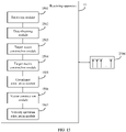
- the transmission apparatus 13 in FIG. 13 includes the following modules:
- the time division multiplexing repetition cycle includes one single-antenna transmit mode sub-cycle and L consecutive multi-antenna transmit mode sub-cycles.
- the single-antenna transmit mode sub-cycle includes N frequency sweep cycles of the chirp signals, and chirp signals in the N frequency sweep cycles are transmitted by one of the M antennas, or are simultaneously transmitted by at least two of the M antennas, where there is a delay between the at least two antennas.
- Each multi-antenna transmit mode sub-cycle includes M frequency sweep cycles of the chirp signals, and chirp signals in the M frequency sweep cycles are respectively transmitted in order by the M antennas.
- the transmit antenna in the single-antenna transmit mode sub-cycle always transmits the (K+1) th chirp signal in the multi-antenna transmit mode sub-cycle.
- M and N are integers greater than 1
- L is a positive integer
- K is an integer greater than or equal to 0.
- the delay between the at least two antennas is a relatively low delay, is preferably an integer multiple of a fast sampling cycle Ts, and is used to offset a signal transmission path length difference caused by an antenna position difference, so that simultaneously transmitting velocity measurement signals by the at least two antennas can be considered, in terms of effect, as transmitting the velocity measurement signals by one antenna.
- the order includes a preset order or a randomly generated order, and orders in the L multi-antenna transmit mode sub-cycles are the same.
- Embodiment 4 includes the following several preferred setting manners.
- a ratio of N to L is greater than a first threshold.
- a value of the first threshold should ensure that no obvious target ambiguity caused due to undersampling of a slow sampling part in a Doppler dimension occurs in a target part of a Doppler profile (Doppler Profile).
- values of L, M, and N should ensure that a ratio of a quantity of 0s to a quantity of non-0 values in a weight function w does not exceed a second threshold
- the weight function w c ⁇ c -
- c is a vector that includes N + L ⁇ M elements
- c - represents vector inversion of c
- ⁇ represents a linear convolution operation of the vector
- the N + L ⁇ M elements correspond to transmit antennas of N + L ⁇ M chirp signals in one time division multiplexing repetition cycle
- an element corresponding to a transmit antenna in the single-antenna transmit mode sub-cycle is 1, and elements corresponding to the other M-1 antennas than the transmit antenna in the single-antenna transmit mode sub-cycle are 0s.
- a time interval between the single-antenna transmit mode sub-cycle and the multi-antenna transmit mode sub-cycle is zero, or is an integer multiple of the frequency sweep cycle.
- a maximum velocity measurement range can be increased and entire velocity measurement signal duration can be minimized while a relatively large virtual aperture is retained in Embodiment 4 of the present invention.
- the velocity measurement signal transmission apparatus provided in Embodiment 4 of the present invention may be used in a vehicle or a radar.
- the vehicle or the radar further includes a plurality of transmit antennas 1303.
- the transmission module 1302 in the transmission apparatus 13 transmits the plurality of chirp signals in the time division multiplexing repetition cycle by using the plurality of transmit antennas 1303.
- the radar includes but is not limited to a millimeter wave radar, a laser radar, and an ultrasonic radar.
- Embodiment 5 of the present invention provides a velocity measurement signal transmission apparatus.
- the transmission apparatus 14 in FIG. 14 includes a memory 1401 and a processor 1402.
- the memory 1401 stores computer program instructions
- the processor 1402 runs the computer program instructions to perform the velocity measurement signal transmission method described in Embodiment 1 or Embodiment 2 shown in FIG. 3 .
- the processor 1402 includes but is not limited to various types of CPUs, DSPs, microcontrollers, microprocessors, or artificial intelligence processors.
- the velocity measurement signal transmission apparatus provided in Embodiment 5 of the present invention may be used in a vehicle or a radar.
- the vehicle or the radar further includes a plurality of transmit antennas 1403, configured to transmit, in a time division multiplexing repetition cycle, a plurality of chirp signals fed from the transmission apparatus 14.
- the radar includes but is not limited to a millimeter wave radar, a laser radar, and an ultrasonic radar.
- Embodiment 6 of the present invention provides a velocity measurement signal receiving apparatus.
- the receiving apparatus 15 in FIG. 15 includes the following modules:
- the calculating a velocity spectrum about moving velocities of the targets based on the vector r includes: calculating the velocity spectrum about the moving velocities of the one or more targets based on the vector r by using a fast Fourier transform (FFT), digital beamforming (DBF), or multiple signal classification (MUSIC) algorithm.
- FFT fast Fourier transform
- DBF digital beamforming
- MUSIC multiple signal classification
- the forming a vector r by using the plurality of elements includes: if at least two of the plurality of elements correspond to a same exponential coefficient, calculating an average value of the at least two elements as an element for forming the vector r, or selecting one of the at least two elements as an element for forming the vector r.
- the velocity measurement signal receiving apparatus provided in Embodiment 6 of the present invention may be used in a vehicle or a radar.
- the vehicle or the radar further includes a plurality of receive antennas 1508, and the receiving module 1501 in the receiving apparatus 15 receives, by using the plurality of receive antennas 1508, the received signal reflected by the one or more moving targets.
- the radar includes but is not limited to a millimeter wave radar, a laser radar, and an ultrasonic radar.
- One or more of the modules in the foregoing Embodiment 4 and Embodiment 6 may be implemented by software, hardware, firmware, or a combination thereof.
- the software or firmware includes but is not limited to computer program instructions or code, and may be executed by a hardware processor.
- the hardware includes but is not limited to various integrated circuits, for example, a central processing unit (CPU), a digital signal processor (DSP), a field programmable gate array (FPGA), or an application-specific integrated circuit (ASIC).
- CPU central processing unit
- DSP digital
- Embodiment 7 of the present invention provides a velocity measurement signal receiving apparatus.
- the receiving apparatus 16 in FIG. 16 includes a memory 1601 and a processor 1602.
- the memory 1601 stores computer program instructions
- the processor 1602 runs the computer program instructions to perform the velocity measurement signal receiving method described in Embodiment 3 shown in FIG. 7 .
- the processor 1602 includes but is not limited to various types of CPUs, DSPs, microcontrollers, microprocessors, or artificial intelligence processors.
- the velocity measurement signal receiving apparatus may be used in a vehicle or a radar.
- the vehicle or the radar further includes a plurality of receive antennas 1603, configured to receive a received signal reflected by one or more moving targets, and provide the received signal for the receiving apparatus 16.
- the radar includes but is not limited to a millimeter wave radar, a laser radar, and an ultrasonic radar.
- All the foregoing embodiments of the present invention may be applied to an intelligent driving tool with a velocity measurement requirement, such as a motor vehicle, a non-motor vehicle, a train, or an aircraft, or may be applied to a device with a velocity measurement function, such as a radar or a sensor.
- Application scenarios include but are not limited to assisted driving and unmanned driving.
- the program may be stored in a computer-readable storage medium.
- the foregoing storage medium includes various media that can store program code, such as a ROM, a RAM, a magnetic disk, or an optical disc.
- All or some of the foregoing embodiments may be implemented through software, hardware, firmware, or any combination thereof.
- the embodiments may be implemented completely or partially in a form of a computer program product.
- the computer program product includes one or more computer instructions.
- the computer program instructions When the computer program instructions are loaded and executed on a computer, the procedures or functions according to the embodiments of the present invention are all or partially generated.
- the computer may be a general-purpose computer, a dedicated computer, a computer network, or another programmable apparatus.
- the computer instructions may be stored in a computer readable storage medium or may be transmitted from a computer readable storage medium to another computer readable storage medium.
- the computer instructions may be transmitted from a website, computer, server, or data center to another website, computer, server, or data center in a wired (for example, a coaxial cable, an optical fiber, or a digital subscriber line (DSL)) or wireless (for example, infrared, radio, or microwave) manner.
- the computer-readable storage medium may be any usable medium accessible by a computer, or a data storage device, for example, a server or a data center, integrating one or more usable media.
- the usable medium may be a magnetic medium (for example, a floppy disk, a hard disk, or a magnetic tape), an optical medium (for example, a DVD), a semiconductor medium (for example, a solid-state drive (Solid State Disk, SSD)), or the like.
- a magnetic medium for example, a floppy disk, a hard disk, or a magnetic tape
- an optical medium for example, a DVD
- a semiconductor medium for example, a solid-state drive (Solid State Disk, SSD)
Landscapes
- Engineering & Computer Science (AREA)
- Radar, Positioning & Navigation (AREA)
- Remote Sensing (AREA)
- Computer Networks & Wireless Communication (AREA)
- Physics & Mathematics (AREA)
- Signal Processing (AREA)
- General Physics & Mathematics (AREA)
- Electromagnetism (AREA)
- Radar Systems Or Details Thereof (AREA)
Abstract
Description
- This application relates to velocity measurement technologies, and in particular, to a velocity measurement signal transmission method and receiving method.
- Velocity measurement includes measuring moving velocities of targets such as a pedestrian, an animal, a motor vehicle, a non-motor vehicle, a train, and an aircraft, and is an important research field of intelligent driving. In practical application, a sensor (such as a millimeter wave radar or a laser radar) that can transmit a velocity measurement signal and receive a velocity measurement signal reflected back by a target is usually used to measure a velocity. The velocity measurement mainly uses the Doppler effect principle: When the target approaches the sensor, a reflected signal frequency is higher than a transmit frequency. Conversely, when the target moves away from the sensor, a reflected signal frequency is lower than a transmit frequency. In this way, a relative velocity between the target and the sensor can be calculated by using a change value of the frequency.
- A chirp (Chirp) signal is a common velocity measurement signal, and its frequency changes with time. The change may be a frequency increase or a frequency decrease, and may be a linear change, or may be a non-linear change. If such a signal is converted into audio, it sounds like chirps of a bird, and therefore, the signal is called a chirp signal.
- A frequency modulated continuous waveform (Frequency Modulated Continuous Waveform, FMWC) is a common waveform of chirp signals (for a frequency change of the waveform with time, refer to
FIG. 1 ), and may be obtained by modulating a carrier (such as a cosine wave, a triangular wave, a sawtooth wave, or a pulse square wave) by using a time function f(t) = f 0 + γt (Formula 1), where f 0 is an initial frequency, γ is a chirp rate, t ∈ [0, Tc ], and Tc is a frequency sweep cycle. A plurality of consecutive chirp signals in a form of the frequency modulated continuous waveform shown inFIG. 1 are used as an example to describe a velocity measurement principle. - If a carrier of the FMCW is a cosine signal, a time domain waveform of a chirp signal is:

- Assuming that there is a target with an initial distance r 0 and a velocityv, a reflected signal delay of the nT th chirp signal may be represented as

- A corresponding received signal may be represented as x'(nT, t) = x(t - τn
T ) + n(t) (Formula 4), where n(t) is a noise signal. - Frequency mixing is performed on a transmitted signal and a reflected signal, and output of a frequency mixer is represented as:

- A value of


- Herein,


- Considering that a Doppler frequency is defined as


- In consideration of only a velocity term, this part is discrete sampling performed on a sinusoidal signal with a frequency fd by using a sampling cycle as the frequency sweep cycle Tc. In consideration of the Nyquist sampling theorem, it is required that


- A time division multiplexing (Time-division multiplexing, TDM) mode has advantages such as simple hardware implementation and low mutual coupling effect, and is an important research direction for the radar. The foregoing velocity measurement method may be based on a SIMO (Single-Input Multiple-Output, single-input multiple-output) mode or a MIMO (Multiple-Input Multiple-Output, multiple-input multiple-output) mode. From Formula 9, the following can be learned.
- In the SIMO mode, only a single transmit antenna transmits a chirp signal, the sampling cycle Tc is a single frequency sweep cycle, and a velocity estimation range is the largest. However, in the SIMO mode, an additional virtual array aperture cannot be obtained, and consequently, angular resolution is reduced.
- In the MIMO mode, it is assumed that there are MT transmit antennas, and the transmit antennas transmit chirp signals in turn, so that a relatively large virtual aperture can be obtained, and angular resolution can be greatly improved. However, the sampling cycle increases to MTTc. This causes a decrease of the maximum velocity measurement range by an MT multiple, and velocity estimation is ambiguous.
- A solution that can be easily implemented is urgently needed to increase a maximum velocity measurement range and minimize entire velocity measurement signal duration while a relatively large virtual aperture is retained.
- To overcome the foregoing problems in the conventional technology, embodiments of the present invention provide a velocity measurement signal transmission method and receiving method.
- According to a first aspect, a velocity measurement signal transmission method is provided, including: generating a plurality of chirp signals for measuring moving velocities of one or more moving targets; and transmitting the plurality of chirp signals in a time division multiplexing repetition cycle by using M antennas. The time division multiplexing repetition cycle includes one single-antenna transmit mode sub-cycle and L consecutive multi-antenna transmit mode sub-cycles. The single-antenna transmit mode sub-cycle includes N frequency sweep cycles, and N chirp signals in the N frequency sweep cycles are transmitted by one of the M antennas, or are simultaneously transmitted by at least two of the M antennas, where there is a delay between the at least two antennas. Each multi-antenna transmit mode sub-cycle includes M frequency sweep cycles, and M chirp signals in the M frequency sweep cycles are respectively transmitted in order by the M antennas. M and N are positive integers greater than 1, and L is a positive integer.
- Optionally, the delay between the at least two antennas is a relatively low delay, is preferably an integer multiple of a fast sampling cycle Ts, and is used to offset a signal transmission path length difference caused by an antenna position difference, so that simultaneously transmitting velocity measurement signals by the at least two antennas can be considered, in terms of effect, as transmitting the velocity measurement signals by one antenna. This avoids an FOV (Field of View, field of view) decrease caused by an undesired BF (Beamforming, beamforming) effect, and greatly increases an SNR (Signal to Noise Ratio, signal to noise ratio). The order includes a preset order or a randomly generated order, and orders in the L multi-antenna transmit mode sub-cycles are the same. According to the foregoing transmission method in which SIMO and MIMO are combined, a maximum velocity measurement range can be increased and entire velocity measurement signal duration can be minimized while a relatively large virtual aperture is retained.
- According to the first aspect, in a first possible implementation of the velocity measurement signal transmission method, a ratio of N to L is greater than a first threshold.
- According to the first aspect or the first possible implementation of the first aspect, in a second possible implementation of the velocity measurement signal transmission method, values of L, M, and N should ensure that a ratio of a quantity of 0s to a quantity of non-0 values in a weight function w does not exceed a second threshold, the weight function w = c ⊗ c -, c is a vector that includes N + L × M elements, c - represents vector inversion of c, ⊗ represents a linear convolution operation of the vector, the N + L × M elements correspond to transmit antennas of N + L × M chirp signals in one time division multiplexing repetition cycle starting from the single-antenna transmit mode sub-cycle or the L consecutive multi-antenna transmit mode sub-cycles, an element corresponding to a transmit antenna in the single-antenna transmit mode sub-cycle is 1, and elements corresponding to the other M-1 antennas than the transmit antenna in the single-antenna transmit mode sub-cycle are 0s.
- According to any one of the first aspect or the implementations of the first aspect, in a third possible implementation of the velocity measurement signal transmission method, a time interval between the single-antenna transmit mode sub-cycle and the multi-antenna transmit mode sub-cycle is zero, or is an integer multiple of the frequency sweep cycle.
- According to any one of the first aspect or the implementations of the first aspect, in a fourth possible implementation of the velocity measurement signal transmission method, the transmit antenna in the single-antenna transmit mode sub-cycle transmits the (K+1)th chirp signal in the multi-antenna transmit mode sub-cycle, where K is an integer greater than or equal to 0, and a relationship among M, N, and K satisfies: if K=0, N≥M-1; if 0<K≤M, N≥M; or if K>M, N≥K+1.
- In the foregoing four implementations, limitations on M, N, L, K, and the time interval between the single-antenna transmit mode sub-cycle and the multi-antenna transmit mode sub-cycle are all intended to increase a maximum velocity measurement range as much as possible while a relatively large virtual aperture is retained.
- According to a second aspect, a velocity measurement signal transmission apparatus is provided, including: a measurement signal generation module, configured to generate a plurality of chirp signals for measuring moving velocities of one or more moving targets; and a transmission module, configured to transmit the plurality of chirp signals in a time division multiplexing repetition cycle by using M antennas. The time division multiplexing repetition cycle includes one single-antenna transmit mode sub-cycle and L consecutive multi-antenna transmit mode sub-cycles. The single-antenna transmit mode sub-cycle includes N frequency sweep cycles of the chirp signals, and chirp signals in the N frequency sweep cycles are transmitted by one of the M antennas, or are simultaneously transmitted by at least two of the M antennas, where there is a delay between the at least two antennas. Each multi-antenna transmit mode sub-cycle includes M frequency sweep cycles of the chirp signals, and chirp signals in the M frequency sweep cycles are respectively transmitted in order by the M antennas. M and N are positive integers greater than 1, and L is a positive integer.
- Optionally, the delay between the at least two antennas is a relatively low delay, is preferably an integer multiple of a fast sampling cycle Ts, and is used to offset a signal transmission path length difference caused by an antenna position difference, so that simultaneously transmitting velocity measurement signals by the at least two antennas can be considered, in terms of effect, as transmitting the velocity measurement signals by one antenna. This avoids an FOV (Field of View, field of view) decrease caused by an undesired BF (Beamforming, beamforming) effect, and greatly increases an SNR (Signal to Noise Ratio, signal to noise ratio). The order includes a preset order or a randomly generated order, and orders in the L multi-antenna transmit mode sub-cycles are the same. According to the foregoing transmission apparatus in which SIMO and MIMO are combined, a maximum velocity measurement range can be increased and entire velocity measurement signal duration can be minimized while a relatively large virtual aperture is retained.
- According to the second aspect, in a first possible implementation of the velocity measurement signal transmission apparatus, a ratio of N to L is greater than a first threshold.
- According to the second aspect or the first possible implementation of the second aspect, in a second possible implementation of the velocity measurement signal transmission apparatus, values of L, M, and N should ensure that a ratio of a quantity of 0s to a quantity of non-0 values in a weight function w does not exceed a second threshold, the weight function w = c ⊗ c -, c is a vector that includes N + L × M elements, c - represents vector inversion of c, ⊗ represents a linear convolution operation of the vector, the N + L × M elements correspond to transmit antennas of N + L × M chirp signals in one time division multiplexing repetition cycle starting from the single-antenna transmit mode sub-cycle or the L consecutive multi-antenna transmit mode sub-cycles, an element corresponding to a transmit antenna in the single-antenna transmit mode sub-cycle is 1, and elements corresponding to the other M-1 antennas than the transmit antenna in the single-antenna transmit mode sub-cycle are 0s.
- According to any one of the second aspect or the implementations of the second aspect, in a third possible implementation of the velocity measurement signal transmission apparatus, a time interval between the single-antenna transmit mode sub-cycle and the multi-antenna transmit mode sub-cycle is zero, or is an integer multiple of the frequency sweep cycle of the chirp signals.
- According to any one of the second aspect or the implementations of the second aspect, in a fourth possible implementation of the velocity measurement signal transmission apparatus, the transmit antenna in the single-antenna transmit mode sub-cycle transmits the (K+1)th chirp signal in the multi-antenna transmit mode sub-cycle, where K is an integer greater than or equal to 0, and a relationship among M, N, and K satisfies: if K=0, N≥M-1; if 0<K≤M, N≥M; or if K>M, N≥K+1.
- In the foregoing four implementations, limitations on M, N, L, K, and the time interval between the single-antenna transmit mode sub-cycle and the multi-antenna transmit mode sub-cycle are all intended to increase a maximum velocity measurement range as much as possible while a relatively large virtual aperture is retained.
- According to a third aspect, a velocity measurement signal receiving method is provided, including: receiving, by using a plurality of antennas, received signals reflected by one or more moving targets, where the received signals include chirp signals in one or more time division multiplexing repetition cycles, each time division multiplexing repetition cycle includes one single-antenna transmit mode sub-cycle and L consecutive multi-antenna transmit mode sub-cycles, each single-antenna transmit mode sub-cycle includes N frequency sweep cycles, each multi-antenna transmit mode sub-cycle includes M frequency sweep cycles, and N chirp signals in the N frequency sweep cycles and a chirp signal in the Kth frequency sweep cycle in the M frequency sweep cycles are transmitted by a same antenna, where L, M, N, and K are all positive integers, and both M and N are greater than 1; for a received signal received by each of the plurality of antennas, sampling a chirp signal in one of the one or more time division multiplexing repetition cycles by using the frequency sweep cycle as a sampling cycle, to obtain data corresponding to N+L sampling points, where the N+L sampling points are respectively in the N frequency sweep cycles in the single-antenna transmit mode sub-cycle and the Kth frequency sweep cycle in each of the L consecutive multi-antenna transmit mode sub-cycles; constructing a target vector by using the data corresponding to the N+L sampling points corresponding to each of the plurality of antennas; constructing a target matrix X by using a plurality of target vectors of the plurality of antennas; calculating a covariance matrix R of the target matrix X; sequentially extracting a plurality of elements in the matrix R in an order of exponential coefficients of the plurality of elements, and forming a vector r by using the plurality of elements; and calculating a velocity spectrum about moving velocities of the one or more targets based on the vector r. According to the foregoing method for selecting a sampling point and method for processing data corresponding to the sampling point, a maximum velocity measurement range can be increased and entire velocity measurement signal duration can be minimized while a relatively large virtual aperture is retained.
- According to the third aspect, in a first possible implementation of the velocity measurement signal receiving method, the calculating a velocity spectrum about moving velocities of the targets based on the vector r includes: calculating the velocity spectrum about the moving velocities of the one or more targets based on the vector r by using a fast Fourier transform (FFT), digital beamforming (DBF), or multiple signal classification (MUSIC) algorithm.
- According to the third aspect or the first possible implementation of the third aspect, in a second possible implementation of the velocity measurement signal receiving method, the forming a vector r by using the plurality of elements includes: if at least two of the plurality of elements correspond to a same exponential coefficient, calculating an average value of the at least two elements as an element for forming the vector r, or selecting one of the at least two elements as an element for forming the vector r.
- According to a fourth aspect, a velocity measurement signal receiving apparatus is provided, including: a receiving module, configured to receive, by using a plurality of antennas, a received signal reflected by one or more moving targets, where the received signal includes a chirp signal in one or more time division multiplexing repetition cycles, each time division multiplexing repetition cycle includes one single-antenna transmit mode sub-cycle and L consecutive multi-antenna transmit mode sub-cycles, each single-antenna transmit mode sub-cycle includes N frequency sweep cycles, each multi-antenna transmit mode sub-cycle includes M frequency sweep cycles, and N chirp signals in the N frequency sweep cycles and a chirp signal in the Kth frequency sweep cycle in the M frequency sweep cycles are transmitted by a same antenna, where L, M, N, and K are all positive integers, and both M and N are greater than 1; a data obtaining module, configured to: for a received signal received by each of the plurality of antennas, sample a chirp signal in one of the one or more time division multiplexing repetition cycles by using the frequency sweep cycle as a sampling cycle, to obtain data corresponding to N+L sampling points, where the N+L sampling points are respectively in the N frequency sweep cycles in the single-antenna transmit mode sub-cycle and the Kth frequency sweep cycle in each of the L consecutive multi-antenna transmit mode sub-cycles; a target vector construction module, configured to construct a target vector by using the data corresponding to the N+L sampling points corresponding to each of the plurality of antennas; a target matrix construction module, configured to construct a target matrix X by using a plurality of target vectors of the plurality of antennas; a covariance calculation module, configured to calculate a covariance matrix R of the target matrix X; a vector construction module, configured to sequentially extract a plurality of elements in the matrix R in an order of exponential coefficients of the plurality of elements, and form a vector r by using the plurality of elements; and a velocity spectrum calculation module, configured to calculate a velocity spectrum about moving velocities of the one or more targets based on the vector r. In the velocity measurement signal receiving apparatus with the foregoing structure, a maximum velocity measurement range can be increased and entire velocity measurement signal duration can be minimized while a relatively large virtual aperture is retained.
- According to the fourth aspect, in a first possible implementation of the velocity measurement signal receiving apparatus, the calculating a velocity spectrum about moving velocities of the targets based on the vector r includes: calculating the velocity spectrum about the moving velocities of the one or more targets based on the vector r by using a fast Fourier transform (FFT), digital beamforming (DBF), or multiple signal classification (MUSIC) algorithm.
- According to the fourth aspect or the first possible implementation of the fourth aspect, in a second possible implementation of the velocity measurement signal receiving apparatus, the forming a vector r by using the plurality of elements includes: if at least two of the plurality of elements correspond to a same exponential coefficient, calculating an average value of the at least two elements as an element for forming the vector r, or selecting one of the at least two elements as an element for forming the vector r.
- According to a fifth aspect, a velocity measurement signal transmission apparatus is provided, including a memory and a processor. The memory stores computer program instructions, and the processor runs the computer program instructions to perform the velocity measurement signal transmission method in any one of the first aspect or the implementations of the first aspect.
- According to a sixth aspect, a velocity measurement signal receiving apparatus is provided, including a memory and a processor. The memory stores computer program instructions, and the processor runs the computer program instructions to perform the velocity measurement signal receiving method in any one of the third aspect or the implementations of the third aspect.
- According to a seventh aspect, a computer storage medium is provided, including computer instructions. When the computer instructions are run by a processor, a transmission apparatus is enabled to perform the velocity measurement signal transmission method in any one of the first aspect or the implementations of the first aspect.
- According to an eighth aspect, a computer storage medium is provided, including computer instructions. When the computer instructions are run by a processor, a receiving apparatus is enabled to perform the velocity measurement signal receiving method in any one of the third aspect or the implementations of the third aspect.
- According to a ninth aspect, a computer program product is provided. When the computer program product runs on a processor, a transmission apparatus is enabled to perform the velocity measurement signal transmission method in any one of the first aspect or the implementations of the first aspect.
- According to a tenth aspect, a computer program product is provided. When the computer program product runs on a processor, a receiving apparatus is enabled to perform the velocity measurement signal receiving method in any one of the third aspect or the implementations of the third aspect.
- According to an eleventh aspect, a vehicle is provided, including the M antennas and the transmission apparatus in any one of the second aspect and the implementations of the second aspect or the fifth aspect.
- According to a twelfth aspect, a vehicle is provided, including the plurality of antennas and the receiving apparatus in any one of the fourth aspect and the implementations of the fourth aspect or the sixth aspect.
- According to a thirteenth aspect, a radar is provided, including the M antennas and the transmission apparatus in any one of the second aspect and the implementations of the second aspect or the fifth aspect.
- According to a fourteenth aspect, a radar is provided, including the plurality of antennas and the receiving apparatus in any one of the fourth aspect and the implementations of the fourth aspect or the sixth aspect.
- To describe the technical solutions in embodiments of the present invention or in the prior art more clearly, the following briefly describes the accompanying drawings for describing embodiments or the prior art. It is clear that the accompanying drawings in the following description show some embodiments of the present invention, and a person of ordinary skill in the art may still derive other drawings from these accompanying drawings without creative efforts.
-
FIG. 1 is a schematic diagram of a situation of a change, with time, of frequencies of a plurality of consecutive chirp signals that are in a form of a frequency modulated continuous wave and that are used for velocity measurement in the conventional technology; -
FIG. 2 is a schematic diagram of a typical application scenario of velocity measurement according to embodiments of the present invention; -
FIG. 3 is a flowchart of a velocity measurement signal transmission method according toEmbodiment 1 andEmbodiment 2 of the present invention; -
FIG. 4 is a schematic diagram in which M antennas transmit a plurality of chirp signals in a time division multiplexing repetition cycle according toEmbodiment 1 of the present invention; -
FIG. 5 is a schematic diagram in which M antennas transmit a plurality of chirp signals in a time division multiplexing repetition cycle according toEmbodiment 2 of the present invention; -
FIG. 6 is a schematic diagram of a delay of simultaneously sending a plurality of chirp signals by a plurality of antennas in a single-antenna transmit mode sub-cycle according toEmbodiment 2 of the present invention; -
FIG. 7 is a flowchart of a velocity measurement signal receiving method according toEmbodiment 3 of the present invention; -
FIG. 8 is a schematic diagram of a data sampling manner according toEmbodiment 3 of the present invention; -
FIG. 9 is a schematic diagram of a phase relationship of a plurality of chirp signals received by each antenna according toEmbodiment 3 of the present invention; -
FIG. 10 is a schematic diagram of an example transmit antenna multiplexing manner for describingEmbodiment 3 of the present invention; -
FIG. 11 is an example simulation effect diagram of a velocity spectrum according toEmbodiment 3 of the present invention; -
FIG. 12 is an example RD-map of actual velocity measurement according toEmbodiment 3 of the present invention; -
FIG. 13 is a block diagram of a structure of a vehicle/radar including a velocity measurement signal transmission apparatus according to Embodiment 4 of the present invention; -
FIG. 14 is a block diagram of a structure of a vehicle/radar including a velocity measurement signal transmission apparatus according toEmbodiment 5 of the present invention; -
FIG. 15 is a block diagram of a structure of a vehicle/radar including a velocity measurement signal receiving apparatus according to Embodiment 6 of the present invention; and -
FIG. 16 is a block diagram of a structure of a vehicle/radar including a velocity measurement signal receiving apparatus according to Embodiment 7 of the present invention. - To make the objectives, technical solutions, and advantages of embodiments of the present invention clearer, the following clearly and completely describes the technical solutions in embodiments of the present invention with reference to the accompanying drawings in embodiments of the present invention. It is clear that the described embodiments are some but not all of embodiments of the present invention. All other embodiments obtained by a person of ordinary skill in the art based on embodiments of the present invention without creative efforts shall fall within the protection scope of the present invention.
-
FIG. 2 is a schematic diagram of a typical application scenario of velocity measurement according to embodiments of the present invention. A velocity measurement scenario of outdoor road traffic is shown in the figure. A velocity measurement device transmits velocity measurement signals to one or more moving targets, for example, a vehicle traveling on a road or a walking pedestrian. The one or more moving targets reflect the velocity measurement signals. Digital signal processing is performed, based on a Doppler effect principle, on velocity measurement signals reflected back to the velocity measurement device, to obtain moving velocities of the one or more moving targets. In addition to the outdoor road traffic scenario shown inFIG. 2 , the embodiments of the present invention may be further used for indoor obstacle avoidance, rail traffic, air flight, and road traffic scenarios in a plurality of road forms. The moving target includes but is not limited to a pedestrian, an animal, a motor vehicle, a non-motor vehicle, a train, a subway, or an aircraft. -
Embodiment 1 of the present invention provides a velocity measurement signal transmission method. As shown inFIG. 3 , the method includes the following steps. - Step 301: Generate a plurality of chirp signals for measuring moving velocities of one or more moving targets.
- Step 302: Transmit the plurality of chirp signals in a time division multiplexing repetition cycle by using M antennas.
- In
Embodiment 1, a manner for transmitting the plurality of chirp signals in the time division multiplexing repetition cycle by using the M antennas is shown inFIG. 4 . Each time division multiplexing repetition cycle includes one single-antenna transmit mode sub-cycle and L consecutive multi-antenna transmit mode sub-cycles (each time division multiplexing repetition cycle may start from one single-antenna transmit mode sub-cycle, as shown inFIG. 4 , or may start from L consecutive multi-antenna transmit mode sub-cycles). The single-antenna transmit mode sub-cycle includes N frequency sweep cycles, and N chirp signals in the N frequency sweep cycles are transmitted by one of the M antennas (the chirp signals transmitted by the antenna is filled with gray inFIG. 4 ). The transmit antenna used in the single-antenna transmit mode sub-cycle also needs to be used for sending at least once in each multi-antenna transmit mode sub-cycle. Each multi-antenna transmit mode sub-cycle includes M frequency sweep cycles, M chirp signals in the M frequency sweep cycles are respectively transmitted in order by the M antennas, the order includes a preset order or a randomly generated order, and orders of the L multi-antenna transmit mode sub-cycles are the same. InFIG. 4 , the transmit antenna in the single-antenna transmit mode sub-cycle always transmits the (K+1)th chirp signal in the multi-antenna transmit mode sub-cycle. M and N are integers greater than 1, L is a positive integer, and K is an integer greater than or equal to 0. - The four parameters M, N, L, and K may be optimized, or a limitation on a time interval between the single-antenna transmit mode sub-cycle and the multi-antenna transmit mode sub-cycle may be properly set, to increase a maximum velocity measurement range as much as possible while a relatively large virtual aperture is retained.
Embodiment 1 includes the following several preferred setting manners. - In a first manner, a ratio of N to L is greater than a first threshold. A value of the first threshold should ensure that no obvious target ambiguity caused due to undersampling of a slow sampling part in a Doppler dimension occurs in a target part of a Doppler profile (Doppler Profile).
- In a second manner, values of L, M, and N should ensure that a ratio of a quantity of 0s to a quantity of non-0 values in a weight function w does not exceed a second threshold, the weight function w = c ⊗ c -, c is a vector that includes N + L × M elements, c - represents vector inversion of c, ⊗ represents a linear convolution operation of the vector, the N + L × M elements correspond to transmit antennas of N + L × M chirp signals in one time division multiplexing repetition cycle, an element corresponding to a transmit antenna in the single-antenna transmit mode sub-cycle is 1, and elements corresponding to the other M-1 antennas than the transmit antenna in the single-antenna transmit mode sub-cycle are 0s.
- In a third manner, a time interval between the single-antenna transmit mode sub-cycle and the multi-antenna transmit mode sub-cycle is zero, or is an integer multiple of the frequency sweep cycle.
- In a fourth manner, a relationship among M, N, and K satisfies:
- if K=0, N≥M-1;
- if 0<K≤M, N≥M; or
- if K>M, N≥
K+ 1. -
Embodiment 2 of the present invention provides another velocity measurement signal transmission method. Steps included in the method are also shown inFIG. 3 . A difference betweenEmbodiment 2 andEmbodiment 1 is that the N chirp signals in the N frequency sweep cycles in the single-antenna transmit mode sub-cycle are simultaneously transmitted by at least two of the M antennas inEmbodiment 2.FIG. 5 is an example diagram in which M antennas transmit a plurality of chirp signals in a time division multiplexing repetition cycle inEmbodiment 2. In a single-antenna transmit mode sub-cycle, four antennas simultaneously send four chirp signals. In each multi-antenna transmit mode sub-cycle, the M antennas sequentially transmit M chirp signals, and a frequency sweep cycle of the chirp signals is Tc. - To avoid an FOV (Field of View, field of view) decrease caused by an undesired BF (Beamforming, beamforming) effect, a low delay exists between the at least two antennas, and is used to offset a signal transmission path length difference caused by an antenna position difference, so that simultaneously transmitting velocity measurement signals by the at least two antennas can be considered, in terms of effect, as transmitting the velocity measurement signals by one antenna. In addition, an SNR (Signal to Noise Ratio, signal to noise ratio) can be further greatly increased.
FIG. 6 shows low delays between the four antennas simultaneously transmitting the four chirp signals in the single-antenna transmit mode sub-cycle inFIG. 5 . The four antennas are respectively marked as T0, T1, T2, and T3, and delays of the antennas T1, T2, and T3 are respectively τ1, τ2, and τ3 relative to the reference antenna T0. In a preferred manner, a value of τ is an integer multiple of a fast sampling interval Ts. - According to the foregoing transmission method in which SIMO and MIMO are combined in
Embodiment 1 andEmbodiment 2, a maximum velocity measurement range can be increased and entire velocity measurement signal duration can be minimized while a relatively large virtual aperture is retained. -
Embodiment 3 of the present invention provides a velocity measurement signal receiving method. As shown inFIG. 7 , the method includes the following steps. - Step 701: Receive, by using a plurality of antennas, received signals reflected by one or more moving targets, where the received signals include chirp signals in one or more time division multiplexing repetition cycles, each time division multiplexing repetition cycle includes one single-antenna transmit mode sub-cycle and L consecutive multi-antenna transmit mode sub-cycles, each single-antenna transmit mode sub-cycle includes N frequency sweep cycles, each multi-antenna transmit mode sub-cycle includes M frequency sweep cycles, and N chirp signals in the N frequency sweep cycles and a chirp signal in the Kth frequency sweep cycle in the M frequency sweep cycles are transmitted by a same antenna, where L, M, N, and K are all positive integers, and both M and N are greater than 1.
- Step 702: For a received signal received by each of the plurality of antennas, sample a chirp signal in one of the one or more time division multiplexing repetition cycles by using the frequency sweep cycle as a sampling cycle, to obtain data corresponding to N+L sampling points, where the N+L sampling points are respectively in the N frequency sweep cycles in the single-antenna transmit mode sub-cycle and the Kth frequency sweep cycle in each of the L consecutive multi-antenna transmit mode sub-cycles.
- A specific data sampling manner may be shown in
FIG. 8 . A chirp signal is sampled in a fast sampling cycle Ts in a fast time direction □, and there are Ns sampling points. In a slow time direction □, all chirp signals transmitted by a transmit antenna in a single-antenna transmit mode sub-cycle in one time division multiplexing repetition cycle including one single-antenna transmit mode sub-cycle and a plurality of consecutive multi-antenna transmit mode sub-cycles are sequentially arranged. This is equivalent to that a sampling cycle in the slow time direction is the frequency sweep cycle Tc. Sampling signals on all receive antennas are sequentially arranged in a receive antenna arrangement direction □, and the receive antennas may be sequentially arranged based on an antenna sequence or randomly arranged. InEmbodiment 3, during velocity measurement, performing sampling at a two-dimensional sampling point with a gray grid pattern is equivalent to "for a received signal received by each of the plurality of antennas, sampling a chirp signal in one of the one or more time division multiplexing repetition cycles by using the frequency sweep cycle as a sampling cycle, to obtain data corresponding to N+L sampling points, where the N+L sampling points are respectively in the N frequency sweep cycles in the single-antenna transmit mode sub-cycle and the Kth frequency sweep cycle in each of the L consecutive multi-antenna transmit mode sub-cycles". - First, a phase relationship of a plurality of chirp signals received by each antenna in this embodiment is described. In a multi-antenna time division multiplexing manner for transmitted signals that is shown in the upper half of
FIG. 9 , it may be learned, according to the foregoingFormula 8, that a phase difference between sampling data obtained by sampling (as described in step 702) the plurality of chirp signals received by each antenna is shown in the lower half ofFIG. 9 . - The following describes a digital signal processing process in detail. For ease of description, a transmit antenna multiplexing manner shown in
FIG. 10 is used as an example. One time division multiplexing repetition cycle includes two multi-antenna transmit mode sub-cycles and one single-antenna transmit mode sub-cycle. Four transmit antennas are used to sequentially send four chirp signals in each multi-antenna transmit mode sub-cycle, and the single-antenna transmit mode sub-cycle includes four chirp signals, which are located at the end of the entire time division multiplexing repetition cycle. It can be learned that six chirp signals are transmitted in one time division multiplexing repetition cycle by a transmit antenna in a single-antenna transmit mode sub-cycle. To be specific, instep 702, data of six sampling points can be obtained for measurement signals received by each antenna that are shown inFIG. 10 . - After the measurement signals in the transmit antenna multiplexing manner shown in
FIG. 10 are reflected by the kth moving target, with reference toFIG. 9 , it can be learned that a phase vector of six chirp signals sampled at a receive end is:
- A digit before the frequency sweep cycle Tc in
Formula 10 is an exponential coefficient, and exponential coefficients of the phase vectors are [0, 4, 7, 8, 9, 10]. - Step 703: Construct a target vector by using the data corresponding to the N+L sampling points corresponding to each of the plurality of antennas.
- A received signal of the nth receive antenna may be represented as:

- In the formula, A = [a 1 , ... , aK ],

- Step 704: Construct a target matrix X by using a plurality of target vectors of the plurality of antennas.
- A matrix including received data of MR receive antennas may be denoted as:

R ], N = [ n 1,..., n MR ]. - Step 705: Calculate a covariance matrix R of the target matrix X.
- R = XXH (Formula 13), where the (m, n)th element in the matrix R is

Table 1 0 -4 -7 -8 -9 -10 4 0 -4 -4 -5 -6 7 3 0 -1 -2 -3 8 4 1 0 -1 -2 9 5 2 1 0 -1 10 6 3 2 1 0 - Step 706: Sequentially extract a plurality of elements in the matrix R in an order of exponential coefficients of the plurality of elements, and form a vector r by using the plurality of elements. If at least two of the plurality of elements correspond to a same exponential coefficient, an average value of the at least two elements is calculated as an element for forming the vector r. Alternatively, one of the at least two elements is selected as an element for forming the vector r.
- For example, 21 elements are selected from the elements whose exponential coefficients range from - 10 to 10 in the matrix R, and are arranged in ascending order or descending order to form a vector r whose length is 21. There are two elements whose exponential coefficients are 4 in the foregoing table: the element (2, 1) and the element (4, 2). In this case, an element corresponding to the exponential coefficient 4 in the vector r may be either of the element (2, 1) and the element (4, 2), or may be an average value of the element (2, 1) and the element (4, 2).
- Step 707: Calculate a velocity spectrum about moving velocities of the one or more targets based on the vector r. Specifically, the velocity spectrum about the moving velocities of the one or more targets may be calculated by using a fast Fourier transform (Fast Fourier Transform, FFT), digital beamforming (Digital Beam Forming, DBF), or multiple signal classification (Multiple Signal Classification, MUSIC) algorithm.
- According to the measurement signal receiving method described in this embodiment, a maximum velocity measurement range can be increased and entire velocity measurement signal duration can be minimized while a relatively large virtual aperture is retained. In an example in which the measurement signals shown in
FIG. 10 are received, a maximum velocity estimation range obtained in this embodiment is the same as that in the SIMO mode, that is, a maximum velocity measurement range competitive to the SIMO mode is achieved. In addition, a length requirement on the single-antenna transmit mode sub-cycle is low, and duration of the time division multiplexing repetition cycle is relatively short. -
FIG. 11 is a simulation effect diagram of the velocity spectrum obtained based on the velocity measurement signal receiving method provided inEmbodiment 3 of the present invention. A horizontal axis represents a moving velocity, and a vertical axis represents a velocity spectrum at a corresponding moving velocity. It can be learned that two spectral line peaks appear at two velocities: -10 m/s and 2 m/s. This indicates that there are two moving targets whose moving velocities are respectively -10 m/s and 2 m/s. - The velocity measurement signal receiving method described in
Embodiment 3 of the present invention may further be combined with distance measurement to obtain an RD-map that reflects both a velocity and a distance of a moving target. An operation method is as follows: - Before
step 702 inEmbodiment 3, fast sampling is first performed in the fast sampling cycle Ts in the fast time direction □ shown inFIG. 8 , to obtain Ns fast sampling points, and time domain to frequency domain conversion such as FFT is performed on the Ns fast sampling points, to obtain Ns pieces of fast sampling frequency domain data. In other words, in this step, data in the fast time direction □ inFIG. 8 is successively the Ns pieces of fast sampling frequency domain data. - The data corresponding to the N+L sampling points in
step 702 is fast sampling frequency domain data corresponding to the N+L sampling points. Instep 702, N+L slow sampling points are sequentially set to select the first to the Ns th of the Ns pieces of fast sampling frequency domain data. To be specific,step 703 to step 707 are sequentially performed Ns times, to obtain a velocity spectrum corresponding to each of the Ns pieces of fast sampling frequency domain data. - Distances of the one or more targets can be calculated based on the Ns pieces of fast sampling frequency domain data. Therefore, with reference to the velocity spectrum corresponding to each of the Ns pieces of fast sampling frequency domain data, the RD-map that can comprehensively reflect distance-velocity information can be formed. With reference to
FIG. 12 , a bright color part represents one or more measured moving targets, a horizontal axis is a Range axis and is used to indicate the distances of the one or more moving targets, and a vertical axis is a Doppler axis and is used to indicate the moving velocities of the one or more moving targets. It should be noted that the RD-map can be obtained in this manner only when the velocity measurement signal is a chirp signal whose frequency changes linearly with time. - Embodiment 4 of the present invention provides a velocity measurement signal transmission apparatus. The
transmission apparatus 13 inFIG. 13 includes the following modules: - a measurement
signal generation module 1301, configured to generate a plurality of chirp signals for measuring moving velocities of one or more moving targets; and - a
transmission module 1302, configured to transmit the plurality of chirp signals in a time division multiplexing repetition cycle by using M antennas. - The time division multiplexing repetition cycle includes one single-antenna transmit mode sub-cycle and L consecutive multi-antenna transmit mode sub-cycles. The single-antenna transmit mode sub-cycle includes N frequency sweep cycles of the chirp signals, and chirp signals in the N frequency sweep cycles are transmitted by one of the M antennas, or are simultaneously transmitted by at least two of the M antennas, where there is a delay between the at least two antennas. Each multi-antenna transmit mode sub-cycle includes M frequency sweep cycles of the chirp signals, and chirp signals in the M frequency sweep cycles are respectively transmitted in order by the M antennas. The transmit antenna in the single-antenna transmit mode sub-cycle always transmits the (K+1)th chirp signal in the multi-antenna transmit mode sub-cycle. M and N are integers greater than 1, L is a positive integer, and K is an integer greater than or equal to 0.
- The delay between the at least two antennas is a relatively low delay, is preferably an integer multiple of a fast sampling cycle Ts, and is used to offset a signal transmission path length difference caused by an antenna position difference, so that simultaneously transmitting velocity measurement signals by the at least two antennas can be considered, in terms of effect, as transmitting the velocity measurement signals by one antenna. This avoids an FOV (Field of View, field of view) decrease caused by an undesired BF (Beamforming, beamforming) effect, and greatly increases an SNR (Signal to Noise Ratio, signal to noise ratio).
- The order includes a preset order or a randomly generated order, and orders in the L multi-antenna transmit mode sub-cycles are the same.
- The four parameters M, N, L, and K may be optimized, or a limitation on a time interval between the single-antenna transmit mode sub-cycle and the multi-antenna transmit mode sub-cycle may be properly set, to increase a maximum velocity measurement range as much as possible while a relatively large virtual aperture is retained. Embodiment 4 includes the following several preferred setting manners.
- In a first manner, a ratio of N to L is greater than a first threshold. A value of the first threshold should ensure that no obvious target ambiguity caused due to undersampling of a slow sampling part in a Doppler dimension occurs in a target part of a Doppler profile (Doppler Profile).
- In a second manner, values of L, M, and N should ensure that a ratio of a quantity of 0s to a quantity of non-0 values in a weight function w does not exceed a second threshold, the weight function w = c ⊗ c -, c is a vector that includes N + L × M elements, c - represents vector inversion of c, ⊗ represents a linear convolution operation of the vector, the N + L × M elements correspond to transmit antennas of N + L × M chirp signals in one time division multiplexing repetition cycle, an element corresponding to a transmit antenna in the single-antenna transmit mode sub-cycle is 1, and elements corresponding to the other M-1 antennas than the transmit antenna in the single-antenna transmit mode sub-cycle are 0s.
- In a third manner, a time interval between the single-antenna transmit mode sub-cycle and the multi-antenna transmit mode sub-cycle is zero, or is an integer multiple of the frequency sweep cycle.
- In a fourth manner, a relationship among M, N, and K satisfies:
- if K=0, N≥M-1;
- if 0<K≤M, N≥M; or
- if K>M, N≥
K+ 1. - According to the foregoing transmission apparatus in which SIMO and MIMO are combined, a maximum velocity measurement range can be increased and entire velocity measurement signal duration can be minimized while a relatively large virtual aperture is retained in Embodiment 4 of the present invention.
- The velocity measurement signal transmission apparatus provided in Embodiment 4 of the present invention may be used in a vehicle or a radar. With reference to
FIG. 13 , the vehicle or the radar further includes a plurality of transmitantennas 1303. Thetransmission module 1302 in thetransmission apparatus 13 transmits the plurality of chirp signals in the time division multiplexing repetition cycle by using the plurality of transmitantennas 1303. The radar includes but is not limited to a millimeter wave radar, a laser radar, and an ultrasonic radar. -
Embodiment 5 of the present invention provides a velocity measurement signal transmission apparatus. Thetransmission apparatus 14 inFIG. 14 includes amemory 1401 and aprocessor 1402. Thememory 1401 stores computer program instructions, and theprocessor 1402 runs the computer program instructions to perform the velocity measurement signal transmission method described inEmbodiment 1 orEmbodiment 2 shown inFIG. 3 . Theprocessor 1402 includes but is not limited to various types of CPUs, DSPs, microcontrollers, microprocessors, or artificial intelligence processors. - The velocity measurement signal transmission apparatus provided in
Embodiment 5 of the present invention may be used in a vehicle or a radar. With reference toFIG. 14 , the vehicle or the radar further includes a plurality of transmitantennas 1403, configured to transmit, in a time division multiplexing repetition cycle, a plurality of chirp signals fed from thetransmission apparatus 14. The radar includes but is not limited to a millimeter wave radar, a laser radar, and an ultrasonic radar. - Embodiment 6 of the present invention provides a velocity measurement signal receiving apparatus. The receiving
apparatus 15 inFIG. 15 includes the following modules: - a
receiving module 1501, configured to receive, by using a plurality of antennas, received signals reflected by one or more moving targets, where the received signals include chirp signals in one or more time division multiplexing repetition cycles, each time division multiplexing repetition cycle includes one single-antenna transmit mode sub-cycle and L consecutive multi-antenna transmit mode sub-cycles, each single-antenna transmit mode sub-cycle includes N frequency sweep cycles, each multi-antenna transmit mode sub-cycle includes M frequency sweep cycles, and N chirp signals in the N frequency sweep cycles and a chirp signal in the Kth frequency sweep cycle in the M frequency sweep cycles are transmitted by a same antenna, where L, M, N, and K are all positive integers, and both M and N are greater than 1; - a
data obtaining module 1502, configured to: for a received signal received by each of the plurality of antennas, sample a chirp signal in one of the one or more time division multiplexing repetition cycles by using the frequency sweep cycle as a sampling cycle, to obtain data corresponding to N+L sampling points, where the N+L sampling points are respectively in the N frequency sweep cycles in the single-antenna transmit mode sub-cycle and the Kth frequency sweep cycle in each of the L consecutive multi-antenna transmit mode sub-cycles; - a target
vector construction module 1503, configured to construct a target vector by using the data corresponding to the N+L sampling points corresponding to each of the plurality of antennas; - a target
matrix construction module 1504, configured to construct a target matrix X by using a plurality of target vectors of the plurality of antennas; - a
covariance calculation module 1505, configured to calculate a covariance matrix R of the target matrix X; - a
vector construction module 1506, configured to sequentially extract a plurality of elements in the matrix R in an order of exponential coefficients of the plurality of elements, and form a vector r by using the plurality of elements; and - a velocity
spectrum calculation module 1507, configured to calculate a velocity spectrum about moving velocities of the one or more targets based on the vector r. In the velocity measurement signal receiving apparatus with the foregoing structure, a maximum velocity measurement range can be increased and entire velocity measurement signal duration can be minimized while a relatively large virtual aperture is retained. - The calculating a velocity spectrum about moving velocities of the targets based on the vector r includes: calculating the velocity spectrum about the moving velocities of the one or more targets based on the vector r by using a fast Fourier transform (FFT), digital beamforming (DBF), or multiple signal classification (MUSIC) algorithm.
- The forming a vector r by using the plurality of elements includes: if at least two of the plurality of elements correspond to a same exponential coefficient, calculating an average value of the at least two elements as an element for forming the vector r, or selecting one of the at least two elements as an element for forming the vector r.
- The velocity measurement signal receiving apparatus provided in Embodiment 6 of the present invention may be used in a vehicle or a radar. With reference to
FIG. 15 , the vehicle or the radar further includes a plurality of receiveantennas 1508, and thereceiving module 1501 in the receivingapparatus 15 receives, by using the plurality of receiveantennas 1508, the received signal reflected by the one or more moving targets. The radar includes but is not limited to a millimeter wave radar, a laser radar, and an ultrasonic radar. One or more of the modules in the foregoing Embodiment 4 and Embodiment 6 may be implemented by software, hardware, firmware, or a combination thereof. The software or firmware includes but is not limited to computer program instructions or code, and may be executed by a hardware processor. The hardware includes but is not limited to various integrated circuits, for example, a central processing unit (CPU), a digital signal processor (DSP), a field programmable gate array (FPGA), or an application-specific integrated circuit (ASIC). - Embodiment 7 of the present invention provides a velocity measurement signal receiving apparatus. The receiving
apparatus 16 inFIG. 16 includes amemory 1601 and aprocessor 1602. Thememory 1601 stores computer program instructions, and theprocessor 1602 runs the computer program instructions to perform the velocity measurement signal receiving method described inEmbodiment 3 shown inFIG. 7 . Theprocessor 1602 includes but is not limited to various types of CPUs, DSPs, microcontrollers, microprocessors, or artificial intelligence processors. - The velocity measurement signal receiving apparatus provided in Embodiment 7 of the present invention may be used in a vehicle or a radar. With reference to
FIG. 16 , the vehicle or the radar further includes a plurality of receiveantennas 1603, configured to receive a received signal reflected by one or more moving targets, and provide the received signal for the receivingapparatus 16. The radar includes but is not limited to a millimeter wave radar, a laser radar, and an ultrasonic radar. - All the foregoing embodiments of the present invention may be applied to an intelligent driving tool with a velocity measurement requirement, such as a motor vehicle, a non-motor vehicle, a train, or an aircraft, or may be applied to a device with a velocity measurement function, such as a radar or a sensor. Application scenarios include but are not limited to assisted driving and unmanned driving.
- A person skilled in the art may clearly understand that, descriptions of embodiments provided in this application may be mutually referenced. For ease and brevity of description, for example, for functions of the apparatuses and devices and performed steps that are provided in embodiments of this application, refer to related descriptions in the method embodiments of this application. Reference can also be made between various method embodiments and between various apparatus embodiments.
- A person skilled in the art may understand that all or some of the steps of the method embodiments may be implemented by using hardware related to a program instruction. The program may be stored in a computer-readable storage medium. When the program is run, the steps of the method embodiments are performed. The foregoing storage medium includes various media that can store program code, such as a ROM, a RAM, a magnetic disk, or an optical disc.
- All or some of the foregoing embodiments may be implemented through software, hardware, firmware, or any combination thereof. When software is used for implementation, the embodiments may be implemented completely or partially in a form of a computer program product. The computer program product includes one or more computer instructions. When the computer program instructions are loaded and executed on a computer, the procedures or functions according to the embodiments of the present invention are all or partially generated. The computer may be a general-purpose computer, a dedicated computer, a computer network, or another programmable apparatus. The computer instructions may be stored in a computer readable storage medium or may be transmitted from a computer readable storage medium to another computer readable storage medium. For example, the computer instructions may be transmitted from a website, computer, server, or data center to another website, computer, server, or data center in a wired (for example, a coaxial cable, an optical fiber, or a digital subscriber line (DSL)) or wireless (for example, infrared, radio, or microwave) manner. The computer-readable storage medium may be any usable medium accessible by a computer, or a data storage device, for example, a server or a data center, integrating one or more usable media. The usable medium may be a magnetic medium (for example, a floppy disk, a hard disk, or a magnetic tape), an optical medium (for example, a DVD), a semiconductor medium (for example, a solid-state drive (Solid State Disk, SSD)), or the like.
- In several embodiments provided in this application, it should be understood that the disclosed apparatus and method may be implemented in other manners without departing from the scope of this application. For example, the embodiments described above are merely examples. For example, division into the modules or units is merely logical function division, and may be other division in an actual implementation. For example, a plurality of units or components may be combined or integrated into another system, or some features may be ignored or not performed. The units described as separate parts may or may not be physically separate, and parts displayed as units may or may not be physical units, and may be located in one position, or may be distributed on a plurality of network units. Some or all of the modules may be selected according to an actual requirement to achieve the objectives of the solutions of the embodiments. A person of ordinary skill in the art may understand and implement the embodiments without creative efforts.
- In addition, the apparatus and method described herein, and schematic diagrams of different embodiments can be combined or integrated with other systems, modules, technologies, or methods without departing from the scope of this application. In addition, the displayed or discussed mutual couplings or direct couplings or communication connections may be implemented through some interfaces. The indirect couplings or communication connections between the apparatuses or units may be implemented in electronic, mechanical, or another form.
- The foregoing description is merely specific implementations of this application, but the protection scope of this application is not limited thereto. Any variation or replacement readily figured out by a person skilled in the art within the technical scope disclosed in this application shall fall within the protection scope of this application. Therefore, the protection scope of this application shall be subject to the protection scope of the claims.
Claims (26)
- A velocity measurement signal transmission method, comprising:generating a plurality of chirp signals for measuring moving velocities of one or more moving targets; andtransmitting the plurality of chirp signals in a time division multiplexing repetition cycle by using M antennas, whereinthe time division multiplexing repetition cycle comprises one single-antenna transmit mode sub-cycle and L consecutive multi-antenna transmit mode sub-cycles;the single-antenna transmit mode sub-cycle comprises N frequency sweep cycles, and N chirp signals in the N frequency sweep cycles are transmitted by one of the M antennas, or are simultaneously transmitted by at least two of the M antennas, wherein there is a delay between the at least two antennas;each multi-antenna transmit mode sub-cycle comprises M frequency sweep cycles, and M chirp signals in the M frequency sweep cycles are respectively transmitted in order by the M antennas; andM and N are positive integers greater than 1, and L is a positive integer.
- The method according to claim 1, wherein a ratio of N to L is greater than a first threshold.
- The method according to claim 1 or 2, wherein values of L, M, and N ensure that a ratio of a quantity of 0s to a quantity of non-0 values in a weight function w does not exceed a second threshold, the weight function w = c ⊗ c -, c is a vector that comprises N + L × M elements, c - represents vector inversion of c, ⊗ represents a linear convolution operation of the vector, the N + L × M elements correspond to transmit antennas of N + L × M chirp signals in one time division multiplexing repetition cycle starting from the single-antenna transmit mode sub-cycle or the L consecutive multi-antenna transmit mode sub-cycles, an element corresponding to a transmit antenna in the single-antenna transmit mode sub-cycle is 1, and elements corresponding to the other M-1 antennas than the transmit antenna in the single-antenna transmit mode sub-cycle are 0s.
- The method according to any one of claims 1 to 3, wherein a time interval between the single-antenna transmit mode sub-cycle and the multi-antenna transmit mode sub-cycle is zero, or is an integer multiple of the frequency sweep cycle.
- The method according to any one of claims 1 to 4, wherein the transmit antenna in the single-antenna transmit mode sub-cycle transmits the (K+1)th chirp signal in the multi-antenna transmit mode sub-cycle, wherein K is an integer greater than or equal to 0, and a relationship among M, N, and K satisfies:if K=0, N≥M-1;if 0<K≤M, N≥M; orif K>M, N≥K+1.
- A velocity measurement signal transmission apparatus, comprising:a measurement signal generation module, configured to generate a plurality of chirp signals for measuring moving velocities of one or more moving targets; anda transmission module, configured to transmit the plurality of chirp signals in a time division multiplexing repetition cycle by using M antennas, whereinthe time division multiplexing repetition cycle comprises one single-antenna transmit mode sub-cycle and L consecutive multi-antenna transmit mode sub-cycles;the single-antenna transmit mode sub-cycle comprises N frequency sweep cycles of the chirp signals, and chirp signals in the N frequency sweep cycles are transmitted by one of the M antennas, or are simultaneously transmitted by at least two of the M antennas, wherein there is a delay between the at least two antennas;each multi-antenna transmit mode sub-cycle comprises M frequency sweep cycles of the chirp signals, and chirp signals in the M frequency sweep cycles are respectively transmitted in order by the M antennas; andM and N are positive integers greater than 1, and L is a positive integer.
- The apparatus according to claim 6, wherein a ratio of N to L is greater than a first threshold.
- The apparatus according to claim 6 or 7, wherein values of L, M, and N ensure that a ratio of a quantity of 0s to a quantity of non-0 values in a weight function w does not exceed a second threshold, the weight function w = c ⊗ c -, c is a vector that comprises N + L × M elements, c - represents vector inversion of c, ⊗ represents a linear convolution operation of the vector, the N + L × M elements correspond to transmit antennas of N + L × M chirp signals in one time division multiplexing repetition cycle starting from the single-antenna transmit mode sub-cycle or the L consecutive multi-antenna transmit mode sub-cycles, an element corresponding to a transmit antenna in the single-antenna transmit mode sub-cycle is 1, and elements corresponding to the other M-1 antennas than the transmit antenna in the single-antenna transmit mode sub-cycle are 0s.
- The apparatus according to any one of claims 6 to 8, wherein a time interval between the single-antenna transmit mode sub-cycle and the multi-antenna transmit mode sub-cycle is zero, or is an integer multiple of the frequency sweep cycle of the chirp signals.
- The apparatus according to any one of claims 6 to 9, wherein the transmit antenna in the single-antenna transmit mode sub-cycle transmits the (K+1)th chirp signal in the multi-antenna transmit mode sub-cycle, wherein K is an integer greater than or equal to 0, and a relationship among M, N, and K satisfies:if K=0, N≥M-1;if 0<K≤M, N≥M; orif K>M, N≥K+1.
- A velocity measurement signal transmission apparatus, comprising a memory and a processor, wherein the memory stores computer program instructions, and the processor runs the computer program instructions to perform the operation according to any one of claims 1 to 5.
- A computer storage medium, comprising computer instructions, wherein when the computer instructions are run by a processor, a transmission apparatus is enabled to perform the method according to any one of claims 1 to 5.
- A computer program product, wherein when the computer program product runs on a processor, a transmission apparatus is enabled to perform the method according to any one of claims 1 to 5.
- A velocity measurement signal receiving method, comprising:receiving, by using a plurality of antennas, received signals reflected by one or more moving targets, wherein the received signals comprise chirp signals in one or more time division multiplexing repetition cycles, each time division multiplexing repetition cycle comprises one single-antenna transmit mode sub-cycle and L consecutive multi-antenna transmit mode sub-cycles, each single-antenna transmit mode sub-cycle comprises N frequency sweep cycles, each multi-antenna transmit mode sub-cycle comprises M frequency sweep cycles, and N chirp signals in the N frequency sweep cycles and a chirp signal in the Kth frequency sweep cycle in the M frequency sweep cycles are transmitted by a same antenna, wherein L, M, N, and K are all positive integers, and both M and N are greater than 1;for a received signal received by each of the plurality of antennas, sampling a chirp signal in one of the one or more time division multiplexing repetition cycles by using the frequency sweep cycle as a sampling cycle, to obtain data corresponding to N+L sampling points, wherein the N+L sampling points are respectively in the N frequency sweep cycles in the single-antenna transmit mode sub-cycle and the Kth frequency sweep cycle in each of the L consecutive multi-antenna transmit mode sub-cycles;constructing a target vector by using the data corresponding to the N+L sampling points corresponding to each of the plurality of antennas;constructing a target matrix X by using a plurality of target vectors of the plurality of antennas;calculating a covariance matrix R of the target matrix X;sequentially extracting a plurality of elements in the matrix R in an order of exponential coefficients of the plurality of elements, and forming a vector r by using the plurality of elements; andcalculating a velocity spectrum about moving velocities of the one or more targets based on the vector r.
- The method according to claim 14, wherein the calculating a velocity spectrum about moving velocities of the targets based on the vector r comprises:
calculating the velocity spectrum about the moving velocities of the one or more targets based on the vector r by using a fast Fourier transform (FFT), digital beamforming (DBF), or multiple signal classification (MUSIC) algorithm. - The method according to claim 14 or 15, wherein the forming a vector r by using the plurality of elements comprises:
if at least two of the plurality of elements correspond to a same exponential coefficient, calculating an average value of the at least two elements as an element for forming the vector r, or selecting one of the at least two elements as an element for forming the vector r. - A velocity measurement signal receiving apparatus, comprising:a receiving module, configured to receive, by using a plurality of antennas, a received signal reflected by one or more moving targets, wherein the received signal comprises a chirp signal in one or more time division multiplexing repetition cycles, each time division multiplexing repetition cycle comprises one single-antenna transmit mode sub-cycle and L consecutive multi-antenna transmit mode sub-cycles, each single-antenna transmit mode sub-cycle comprises N frequency sweep cycles, each multi-antenna transmit mode sub-cycle comprises M frequency sweep cycles, and N chirp signals in the N frequency sweep cycles and a chirp signal in the Kth frequency sweep cycle in the M frequency sweep cycles are transmitted by a same antenna, wherein L, M, N, and K are all positive integers, and both M and N are greater than 1;a data obtaining module, configured to: for a received signal received by each of the plurality of antennas, sample a chirp signal in one of the one or more time division multiplexing repetition cycles by using the frequency sweep cycle as a sampling cycle, to obtain data corresponding to N+L sampling points, wherein the N+L sampling points are respectively in the N frequency sweep cycles in the single-antenna transmit mode sub-cycle and the Kth frequency sweep cycle in each of the L consecutive multi-antenna transmit mode sub-cycles;a target vector construction module, configured to construct a target vector by using the data corresponding to the N+L sampling points corresponding to each of the plurality of antennas;a target matrix construction module, configured to construct a target matrix X by using a plurality of target vectors of the plurality of antennas;a covariance calculation module, configured to calculate a covariance matrix R of the target matrix X;a vector construction module, configured to sequentially extract a plurality of elements in the matrix R in an order of exponential coefficients of the plurality of elements, and form a vector r by using the plurality of elements; anda velocity spectrum calculation module, configured to calculate a velocity spectrum about moving velocities of the one or more targets based on the vector r.
- The apparatus according to claim 17, wherein the calculating a velocity spectrum about moving velocities of the targets based on the vector r comprises:
calculating the velocity spectrum about the moving velocities of the one or more targets based on the vector r by using a fast Fourier transform (FFT), digital beamforming (DBF), or multiple signal classification (MUSIC) algorithm. - The apparatus according to claim 17 or 18, wherein the forming a vector r by using the plurality of elements comprises:
if at least two of the plurality of elements correspond to a same exponential coefficient, calculating an average value of the at least two elements as an element for forming the vector r, or selecting one of the at least two elements as an element for forming the vector r. - A velocity measurement signal receiving apparatus, comprising a memory and a processor, wherein the memory stores computer program instructions, and the processor runs the computer program instructions to perform the operation according to any one of claims 14 to 16.
- A computer storage medium, comprising computer instructions, wherein when the computer instructions are run by a processor, a receiving apparatus is enabled to perform the method according to any one of claims 14 to 16.
- A computer program product, wherein when the computer program product runs on a processor, a receiving apparatus is enabled to perform the method according to any one of claims 14 to 16.
- A vehicle, comprising the M antennas and the transmission apparatus according to any one of claims 6 to 11.
- A vehicle, comprising the plurality of antennas and the receiving apparatus according to any one of claims 17 to 20.
- A radar, comprising the M antennas and the transmission apparatus according to any one of claims 6 to 11.
- A radar, comprising the plurality of antennas and the receiving apparatus according to any one of claims 17 to 20.
Applications Claiming Priority (1)
| Application Number | Priority Date | Filing Date | Title |
|---|---|---|---|
| PCT/CN2019/107526 WO2021056187A1 (en) | 2019-09-24 | 2019-09-24 | Transmitting method and receiving method of speed measurement signal |
Publications (3)
| Publication Number | Publication Date |
|---|---|
| EP4024083A1 true EP4024083A1 (en) | 2022-07-06 |
| EP4024083A4 EP4024083A4 (en) | 2022-11-30 |
| EP4024083B1 EP4024083B1 (en) | 2025-09-17 |
Family
ID=75117150
Family Applications (1)
| Application Number | Title | Priority Date | Filing Date |
|---|---|---|---|
| EP19946829.9A Active EP4024083B1 (en) | 2019-09-24 | 2019-09-24 | Transmitting method and receiving method of speed measurement signal |
Country Status (4)
| Country | Link |
|---|---|
| US (1) | US12345801B2 (en) |
| EP (1) | EP4024083B1 (en) |
| CN (1) | CN112585877B (en) |
| WO (1) | WO2021056187A1 (en) |
Families Citing this family (2)
| Publication number | Priority date | Publication date | Assignee | Title |
|---|---|---|---|---|
| DE102022121301A1 (en) * | 2022-08-23 | 2024-02-29 | Technische Universität Dresden, Körperschaft des öffentlichen Rechts | Cognitive radar for clearly measuring speed |
| EP4418000A1 (en) * | 2023-02-17 | 2024-08-21 | IMRA Europe S.A.S. | Radar data processing by dnn |
Family Cites Families (18)
| Publication number | Priority date | Publication date | Assignee | Title |
|---|---|---|---|---|
| US9008854B2 (en) * | 1995-06-07 | 2015-04-14 | American Vehicular Sciences Llc | Vehicle component control methods and systems |
| CN101039497B (en) * | 2007-04-28 | 2012-02-15 | 北京邮电大学 | Method and system for measuring bandwidth channel |
| US8908787B2 (en) | 2009-01-26 | 2014-12-09 | Politecnico Di Milano | Systems and methods for selecting reconfigurable antennas in MIMO systems |
| US8811535B2 (en) * | 2009-07-17 | 2014-08-19 | Mitre Corporation | Time-frequency space constructions of families of signals |
| US8797208B2 (en) * | 2010-12-13 | 2014-08-05 | Sony Corporation | Active radar system and method |
| DE102013209708A1 (en) * | 2013-05-24 | 2014-11-27 | Robert Bosch Gmbh | Method for operating a MIMO radar |
| DE102014201026A1 (en) * | 2014-01-21 | 2015-07-23 | Robert Bosch Gmbh | Method for angle estimation and radar sensor for motor vehicles |
| US9933520B1 (en) * | 2015-06-29 | 2018-04-03 | Waymo Llc | Orthogonal linear frequency modulation for MIMO radar |
| US10261179B2 (en) * | 2016-04-07 | 2019-04-16 | Uhnder, Inc. | Software defined automotive radar |
| WO2017175190A1 (en) * | 2016-04-07 | 2017-10-12 | Uhnder, Inc. | Adaptive transmission and interference cancellation for mimo radar |
| US10274594B2 (en) * | 2016-12-06 | 2019-04-30 | GM Global Technology Operations LLC | Direct Doppler-free velocity measurement in linear frequency modulation radar |
| EP3413077B1 (en) * | 2017-06-09 | 2020-02-19 | Veoneer Sweden AB | Enhanced vertical object detection for a vehicle radar system |
| DE102018102816B3 (en) | 2018-02-08 | 2019-07-04 | Infineon Technologies Ag | RADAR WITH PHASE CORRECTION |
| CN108594233B (en) | 2018-04-24 | 2020-07-14 | 森思泰克河北科技有限公司 | Speed ambiguity resolving method based on MIMO automobile radar |
| CN108387877B (en) * | 2018-05-25 | 2020-03-13 | 中国人民解放军国防科技大学 | Moving target phase correction method of multi-input multi-output radar |
| IL260694A (en) * | 2018-07-19 | 2019-01-31 | Arbe Robotics Ltd | Apparatus and method of two-stage signal processing in a radar system |
| EP4016116B1 (en) * | 2019-08-19 | 2025-12-03 | Shenzhen Yinwang Intelligent Technologies Co., Ltd. | Signal transmission method and device, signal processing method and device, and radar system |
| US11592548B2 (en) * | 2019-09-27 | 2023-02-28 | Intel Corporation | Methods and apparatus to improve doppler velocity estimation |
-
2019
- 2019-09-24 WO PCT/CN2019/107526 patent/WO2021056187A1/en not_active Ceased
- 2019-09-24 CN CN201980052600.3A patent/CN112585877B/en active Active
- 2019-09-24 EP EP19946829.9A patent/EP4024083B1/en active Active
-
2022
- 2022-03-24 US US17/703,081 patent/US12345801B2/en active Active
Also Published As
| Publication number | Publication date |
|---|---|
| US20220214442A1 (en) | 2022-07-07 |
| EP4024083A4 (en) | 2022-11-30 |
| CN112585877B (en) | 2021-10-15 |
| EP4024083B1 (en) | 2025-09-17 |
| US12345801B2 (en) | 2025-07-01 |
| WO2021056187A1 (en) | 2021-04-01 |
| CN112585877A (en) | 2021-03-30 |
Similar Documents
| Publication | Publication Date | Title |
|---|---|---|
| CN111373282B (en) | Radar processing chain for FMCW radar system | |
| US9730219B2 (en) | Method for determining a time multiplexing sequence for a MIMO radar | |
| US12517214B2 (en) | Detection method and signal sending method and apparatus | |
| KR102445130B1 (en) | Method and apparatus for determining the lateral relative velocity component of a radar target | |
| CN104181517B (en) | Method for running multiple-input multiple-output radar | |
| CN106842166A (en) | A kind of solution velocity ambiguity method suitable for LFMCW radar system | |
| US12487322B2 (en) | Device and method with radar signal processing | |
| US12345801B2 (en) | Velocity measurement signal transmission method and receiving method | |
| EP4206730A1 (en) | Method and apparatus with radar signal processing | |
| US20210323560A1 (en) | Vehicle speed calculation method, system, device, and storage medium | |
| Liu et al. | Dynamic indoor mmwave MIMO radar simulation: An image rendering-based approach | |
| KR20210152911A (en) | Method and apparatus of processing radar signal by correcting phase distortion | |
| KR20250155555A (en) | Method for estimating radar angle | |
| CN111596294A (en) | Traffic radar, ranging method, device, medium and electronic equipment | |
| CN113820710B (en) | Target microwave associated imaging method based on frequency agile MIMO radar | |
| US20250172659A1 (en) | Signal processing method, storage medium, radar chip, and integrated circuit | |
| CN209496136U (en) | Millimetre-wave radar tramcar collision early warning system based on MIMO | |
| CN109917371B (en) | Microwave radar measurement method based on improved microwave waveform | |
| Sommer et al. | 3D multiple input single output near field automotive synthetic aperture radar | |
| KR20240035140A (en) | Method and apparatus for radar signal processing | |
| Zheng et al. | A deep learning approach for Doppler unfolding in automotive TDM MIMO radar | |
| KR20260014620A (en) | Method for determining the position and/or speed of an object in road traffic | |
| EP4653908A1 (en) | Joint doppler and angle estimation for mimo radar systems | |
| US20230350013A1 (en) | Radar system and method for performing velocity estimation | |
| KR101742868B1 (en) | Frequency modulated continuous wave chain radar system for detecting unmanned aerial vehicle |
Legal Events
| Date | Code | Title | Description |
|---|---|---|---|
| STAA | Information on the status of an ep patent application or granted ep patent |
Free format text: STATUS: THE INTERNATIONAL PUBLICATION HAS BEEN MADE |
|
| PUAI | Public reference made under article 153(3) epc to a published international application that has entered the european phase |
Free format text: ORIGINAL CODE: 0009012 |
|
| STAA | Information on the status of an ep patent application or granted ep patent |
Free format text: STATUS: REQUEST FOR EXAMINATION WAS MADE |
|
| 17P | Request for examination filed |
Effective date: 20220331 |
|
| AK | Designated contracting states |
Kind code of ref document: A1 Designated state(s): AL AT BE BG CH CY CZ DE DK EE ES FI FR GB GR HR HU IE IS IT LI LT LU LV MC MK MT NL NO PL PT RO RS SE SI SK SM TR |
|
| RIC1 | Information provided on ipc code assigned before grant |
Ipc: G01S 13/92 20060101AFI20220722BHEP |
|
| A4 | Supplementary search report drawn up and despatched |
Effective date: 20221027 |
|
| RIC1 | Information provided on ipc code assigned before grant |
Ipc: G01S 13/92 20060101AFI20221021BHEP |
|
| DAV | Request for validation of the european patent (deleted) | ||
| DAX | Request for extension of the european patent (deleted) | ||
| STAA | Information on the status of an ep patent application or granted ep patent |
Free format text: STATUS: EXAMINATION IS IN PROGRESS |
|
| 17Q | First examination report despatched |
Effective date: 20230724 |
|
| RAP1 | Party data changed (applicant data changed or rights of an application transferred) |
Owner name: SHENZHEN YINWANG INTELLIGENTTECHNOLOGIES CO., LTD. |
|
| GRAP | Despatch of communication of intention to grant a patent |
Free format text: ORIGINAL CODE: EPIDOSNIGR1 |
|
| STAA | Information on the status of an ep patent application or granted ep patent |
Free format text: STATUS: GRANT OF PATENT IS INTENDED |
|
| INTG | Intention to grant announced |
Effective date: 20250314 |
|
| GRAS | Grant fee paid |
Free format text: ORIGINAL CODE: EPIDOSNIGR3 |
|
| GRAA | (expected) grant |
Free format text: ORIGINAL CODE: 0009210 |
|
| STAA | Information on the status of an ep patent application or granted ep patent |
Free format text: STATUS: THE PATENT HAS BEEN GRANTED |
|
| AK | Designated contracting states |
Kind code of ref document: B1 Designated state(s): AL AT BE BG CH CY CZ DE DK EE ES FI FR GB GR HR HU IE IS IT LI LT LU LV MC MK MT NL NO PL PT RO RS SE SI SK SM TR |
|
| REG | Reference to a national code |
Ref country code: GB Ref legal event code: FG4D |
|
| REG | Reference to a national code |
Ref country code: CH Ref legal event code: EP |
|
| REG | Reference to a national code |
Ref country code: IE Ref legal event code: FG4D |
|
| REG | Reference to a national code |
Ref country code: DE Ref legal event code: R096 Ref document number: 602019075995 Country of ref document: DE |
|
| PGFP | Annual fee paid to national office [announced via postgrant information from national office to epo] |
Ref country code: DE Payment date: 20250910 Year of fee payment: 7 |
|
| PGFP | Annual fee paid to national office [announced via postgrant information from national office to epo] |
Ref country code: GB Payment date: 20251009 Year of fee payment: 7 |
|
| PG25 | Lapsed in a contracting state [announced via postgrant information from national office to epo] |
Ref country code: NO Free format text: LAPSE BECAUSE OF FAILURE TO SUBMIT A TRANSLATION OF THE DESCRIPTION OR TO PAY THE FEE WITHIN THE PRESCRIBED TIME-LIMIT Effective date: 20251217 |
|
| REG | Reference to a national code |
Ref country code: LT Ref legal event code: MG9D |
|
| PG25 | Lapsed in a contracting state [announced via postgrant information from national office to epo] |
Ref country code: FI Free format text: LAPSE BECAUSE OF FAILURE TO SUBMIT A TRANSLATION OF THE DESCRIPTION OR TO PAY THE FEE WITHIN THE PRESCRIBED TIME-LIMIT Effective date: 20250917 |
|
| PG25 | Lapsed in a contracting state [announced via postgrant information from national office to epo] |
Ref country code: HR Free format text: LAPSE BECAUSE OF FAILURE TO SUBMIT A TRANSLATION OF THE DESCRIPTION OR TO PAY THE FEE WITHIN THE PRESCRIBED TIME-LIMIT Effective date: 20250917 |
|
| PG25 | Lapsed in a contracting state [announced via postgrant information from national office to epo] |
Ref country code: GR Free format text: LAPSE BECAUSE OF FAILURE TO SUBMIT A TRANSLATION OF THE DESCRIPTION OR TO PAY THE FEE WITHIN THE PRESCRIBED TIME-LIMIT Effective date: 20251218 |
|
| PG25 | Lapsed in a contracting state [announced via postgrant information from national office to epo] |
Ref country code: SE Free format text: LAPSE BECAUSE OF FAILURE TO SUBMIT A TRANSLATION OF THE DESCRIPTION OR TO PAY THE FEE WITHIN THE PRESCRIBED TIME-LIMIT Effective date: 20250917 |
|
| REG | Reference to a national code |
Ref country code: NL Ref legal event code: MP Effective date: 20250917 |
|
| PG25 | Lapsed in a contracting state [announced via postgrant information from national office to epo] |
Ref country code: LV Free format text: LAPSE BECAUSE OF FAILURE TO SUBMIT A TRANSLATION OF THE DESCRIPTION OR TO PAY THE FEE WITHIN THE PRESCRIBED TIME-LIMIT Effective date: 20250917 |
|
| PG25 | Lapsed in a contracting state [announced via postgrant information from national office to epo] |
Ref country code: BG Free format text: LAPSE BECAUSE OF FAILURE TO SUBMIT A TRANSLATION OF THE DESCRIPTION OR TO PAY THE FEE WITHIN THE PRESCRIBED TIME-LIMIT Effective date: 20250917 |
|
| PG25 | Lapsed in a contracting state [announced via postgrant information from national office to epo] |
Ref country code: RS Free format text: LAPSE BECAUSE OF FAILURE TO SUBMIT A TRANSLATION OF THE DESCRIPTION OR TO PAY THE FEE WITHIN THE PRESCRIBED TIME-LIMIT Effective date: 20251217 |
|
| PG25 | Lapsed in a contracting state [announced via postgrant information from national office to epo] |
Ref country code: NL Free format text: LAPSE BECAUSE OF FAILURE TO SUBMIT A TRANSLATION OF THE DESCRIPTION OR TO PAY THE FEE WITHIN THE PRESCRIBED TIME-LIMIT Effective date: 20250917 |
|
| REG | Reference to a national code |
Ref country code: AT Ref legal event code: MK05 Ref document number: 1838723 Country of ref document: AT Kind code of ref document: T Effective date: 20250917 |
|
| PG25 | Lapsed in a contracting state [announced via postgrant information from national office to epo] |
Ref country code: SM Free format text: LAPSE BECAUSE OF FAILURE TO SUBMIT A TRANSLATION OF THE DESCRIPTION OR TO PAY THE FEE WITHIN THE PRESCRIBED TIME-LIMIT Effective date: 20250917 |
|
| PG25 | Lapsed in a contracting state [announced via postgrant information from national office to epo] |
Ref country code: ES Free format text: LAPSE BECAUSE OF FAILURE TO SUBMIT A TRANSLATION OF THE DESCRIPTION OR TO PAY THE FEE WITHIN THE PRESCRIBED TIME-LIMIT Effective date: 20250917 |
|
| PG25 | Lapsed in a contracting state [announced via postgrant information from national office to epo] |
Ref country code: AT Free format text: LAPSE BECAUSE OF FAILURE TO SUBMIT A TRANSLATION OF THE DESCRIPTION OR TO PAY THE FEE WITHIN THE PRESCRIBED TIME-LIMIT Effective date: 20250917 |
|
| PG25 | Lapsed in a contracting state [announced via postgrant information from national office to epo] |
Ref country code: IT Free format text: LAPSE BECAUSE OF FAILURE TO SUBMIT A TRANSLATION OF THE DESCRIPTION OR TO PAY THE FEE WITHIN THE PRESCRIBED TIME-LIMIT Effective date: 20250917 Ref country code: RO Free format text: LAPSE BECAUSE OF FAILURE TO SUBMIT A TRANSLATION OF THE DESCRIPTION OR TO PAY THE FEE WITHIN THE PRESCRIBED TIME-LIMIT Effective date: 20250917 |
|
| PG25 | Lapsed in a contracting state [announced via postgrant information from national office to epo] |
Ref country code: IS Free format text: LAPSE BECAUSE OF FAILURE TO SUBMIT A TRANSLATION OF THE DESCRIPTION OR TO PAY THE FEE WITHIN THE PRESCRIBED TIME-LIMIT Effective date: 20260117 |
|
| PG25 | Lapsed in a contracting state [announced via postgrant information from national office to epo] |
Ref country code: CZ Free format text: LAPSE BECAUSE OF FAILURE TO SUBMIT A TRANSLATION OF THE DESCRIPTION OR TO PAY THE FEE WITHIN THE PRESCRIBED TIME-LIMIT Effective date: 20250917 Ref country code: PT Free format text: LAPSE BECAUSE OF FAILURE TO SUBMIT A TRANSLATION OF THE DESCRIPTION OR TO PAY THE FEE WITHIN THE PRESCRIBED TIME-LIMIT Effective date: 20260119 |
|
| PG25 | Lapsed in a contracting state [announced via postgrant information from national office to epo] |
Ref country code: PL Free format text: LAPSE BECAUSE OF FAILURE TO SUBMIT A TRANSLATION OF THE DESCRIPTION OR TO PAY THE FEE WITHIN THE PRESCRIBED TIME-LIMIT Effective date: 20250917 |
|
| PG25 | Lapsed in a contracting state [announced via postgrant information from national office to epo] |
Ref country code: SK Free format text: LAPSE BECAUSE OF FAILURE TO SUBMIT A TRANSLATION OF THE DESCRIPTION OR TO PAY THE FEE WITHIN THE PRESCRIBED TIME-LIMIT Effective date: 20250917 Ref country code: EE Free format text: LAPSE BECAUSE OF FAILURE TO SUBMIT A TRANSLATION OF THE DESCRIPTION OR TO PAY THE FEE WITHIN THE PRESCRIBED TIME-LIMIT Effective date: 20250917 |
|
| REG | Reference to a national code |
Ref country code: CH Ref legal event code: H13 Free format text: ST27 STATUS EVENT CODE: U-0-0-H10-H13 (AS PROVIDED BY THE NATIONAL OFFICE) Effective date: 20260504 |
|
| REG | Reference to a national code |
Ref country code: CH Ref legal event code: W10 Free format text: ST27 STATUS EVENT CODE: U-0-0-W10-W00 (AS PROVIDED BY THE NATIONAL OFFICE) Effective date: 20260507 |