EP4024024A1 - Supergravity vertical vibration table - Google Patents
Supergravity vertical vibration table Download PDFInfo
- Publication number
- EP4024024A1 EP4024024A1 EP21870567.1A EP21870567A EP4024024A1 EP 4024024 A1 EP4024024 A1 EP 4024024A1 EP 21870567 A EP21870567 A EP 21870567A EP 4024024 A1 EP4024024 A1 EP 4024024A1
- Authority
- EP
- European Patent Office
- Prior art keywords
- dynamic
- static
- accumulator
- table top
- vertical
- Prior art date
- Legal status (The legal status is an assumption and is not a legal conclusion. Google has not performed a legal analysis and makes no representation as to the accuracy of the status listed.)
- Granted
Links
Images
Classifications
-
- G—PHYSICS
- G01—MEASURING; TESTING
- G01M—TESTING STATIC OR DYNAMIC BALANCE OF MACHINES OR STRUCTURES; TESTING OF STRUCTURES OR APPARATUS, NOT OTHERWISE PROVIDED FOR
- G01M7/00—Vibration-testing of structures; Shock-testing of structures
- G01M7/02—Vibration-testing by means of a shake table
-
- G—PHYSICS
- G01—MEASURING; TESTING
- G01M—TESTING STATIC OR DYNAMIC BALANCE OF MACHINES OR STRUCTURES; TESTING OF STRUCTURES OR APPARATUS, NOT OTHERWISE PROVIDED FOR
- G01M7/00—Vibration-testing of structures; Shock-testing of structures
- G01M7/02—Vibration-testing by means of a shake table
- G01M7/022—Vibration control arrangements, e.g. for generating random vibrations
-
- G—PHYSICS
- G01—MEASURING; TESTING
- G01M—TESTING STATIC OR DYNAMIC BALANCE OF MACHINES OR STRUCTURES; TESTING OF STRUCTURES OR APPARATUS, NOT OTHERWISE PROVIDED FOR
- G01M7/00—Vibration-testing of structures; Shock-testing of structures
- G01M7/02—Vibration-testing by means of a shake table
- G01M7/04—Monodirectional test stands
-
- G—PHYSICS
- G01—MEASURING; TESTING
- G01N—INVESTIGATING OR ANALYSING MATERIALS BY DETERMINING THEIR CHEMICAL OR PHYSICAL PROPERTIES
- G01N2203/00—Investigating strength properties of solid materials by application of mechanical stress
- G01N2203/003—Generation of the force
- G01N2203/0032—Generation of the force using mechanical means
- G01N2203/0037—Generation of the force using mechanical means involving a rotating movement, e.g. gearing, cam, eccentric, or centrifuge effects
-
- G—PHYSICS
- G01—MEASURING; TESTING
- G01N—INVESTIGATING OR ANALYSING MATERIALS BY DETERMINING THEIR CHEMICAL OR PHYSICAL PROPERTIES
- G01N3/00—Investigating strength properties of solid materials by application of mechanical stress
- G01N3/08—Investigating strength properties of solid materials by application of mechanical stress by applying steady tensile or compressive forces
- G01N3/16—Investigating strength properties of solid materials by application of mechanical stress by applying steady tensile or compressive forces applied through gearing
- G01N3/165—Investigating strength properties of solid materials by application of mechanical stress by applying steady tensile or compressive forces applied through gearing generated by rotation, i.e. centrifugal force
Definitions
- the present disclosure belongs to a vertical vibration device for physical model tests in the field of centrifuge hypergravity, and in particular, relates to a centrifugal hypergravity vertical vibration table.
- the seismic performance of geotechnical structures is an important physical model test.
- a vibration table test is usually conducted using a vibration table. Specifically, a geotechnical structure model of a reduced size is placed on the vibration table, and then a certain vibration waveform is input to observe the earthquake response of the geotechnical structures under the working conditions to deduce the seismic performance of the real geotechnical structures.
- the vibration table tests are divided into two types: normal gravity vibration table tests and hypergravity vibration table tests, that is, 1 g vibration table tests and hypergravity centrifuge vibration table tests. 1 g represents normal gravity.
- the 1 g vibration table has relatively large defects due to the focus on the area rather than the depth.
- the self-weight stress of the soil body is incorrect, so the response of the site under ground motion cannot be truly reflected, and the real seismic property of tunnels, nuclear power plants, and high dams are also not reflected.
- the normal gravity vibration table is usually a large vibration table (the table top of the vibration table is larger in size) and does not use a centrifuge.
- the hypergravity centrifuge test is a kind of physical model test conducted by a centrifuge.
- the geotechnical model of a reduced size is placed in a high-speed rotating centrifuge, such that the model withstands the action greater than the acceleration of gravity to compensate the self-weight loss of the geotechnical structures caused by model scale.
- the vibration table model test can generate the same self-weight stress as the prototype, truly reflect the dynamic response of the prototype under natural conditions, and reproduce the deformation and damage mechanism of the geotechnical structures under the action of an earthquake.
- a vibration table mounted on a centrifuge can simulate the dynamic response of a large-scale site using the model-scale and time-scale effect of hypergravity.
- the disaster effect caused by the multidirectional ground motion is very prominent: the Wenchuan earthquake produced severe projective landslides, the multidirectional vibration in the Kobe earthquake produced complex soil-structure interactions, resulting in the buckling failure of columns of the Daikai station, and in the Wales earthquake, the frequency of the vertical ground motion was close to the fundamental frequency of the site, causing a large amount of liquefaction in the site.
- the study on the evolution regularity of vertical ground motion and the disaster-causing effect of rock and soil has achieved remarkable results in both theoretical and numerical aspects, but it has not been verified in physical model tests.
- the vertical vibration table only needs to balance the self-weight stress of the model itself in the normal gravity environment, and the vertical balance force that the vibration table needs to provide changes little in the vibration process, so the normal-gravity vertical vibration table can adopt the same driving method in the vertical direction as in the horizontal direction, and the hydraulic control and structural design of the normal-gravity vertical vibration table are relatively less difficult.
- the transition from a normal-gravity device to a hypergravity device creates the following problems:
- an objective of the present disclosure is to provide a vertical vibration table in a centrifugal hypergravity field to model the vertical earthquake ground motion.
- a centrifugal hypergravity vertical vibration table includes a table base and a table top, a vertical electro-hydraulic servo vibration excitation system with preload, a table top guide system, and an accumulator that are disposed on the table base.
- the table top guide system includes a sleeve base, a table top guide shaft, and a table top guide shaft bearing.
- the table top guide shaft is fixedly disposed at a bottom of the table top.
- the table top guide shaft is sleeved on the sleeve base through the table top guide shaft bearing. A bottom of the sleeve base is fixed on the table base.
- the accumulator may include an upward preloading accumulator, a downward preloading accumulator, a dynamic actuating cylinder oil return accumulator, and a dynamic actuating cylinder oil supply accumulator that are disposed on the table top.
- the vertical electro-hydraulic servo vibration excitation system with preload may include a vertical dynamic servo actuator and a vertical static preloading actuator that are arranged up and down coaxially.
- the vertical dynamic servo actuator may include a dynamic actuator sleeve.
- the vertical static preloading actuator may include a static actuator sleeve. A lower end of the static actuator sleeve may be fixed to the table top. A lower end of the dynamic actuator sleeve may be fixedly sleeved on an upper end of the static actuator sleeve coaxially.
- An actuating rod may be disposed in both the static actuator sleeve and the dynamic actuator sleeve. An upper end of the actuating rod may abut against a center of a bottom surface of the table top.
- Three flanges may be formed in an outer circumference of the actuating rod from top to bottom in an axial direction, and may be respectively an upper flange, a middle flange, and a lower flange from top to bottom.
- An outer circumference of the upper flange may be sealedly nested and connected in an inner wall of the dynamic actuator sleeve via an upper sealing ring.
- An outer circumference of the middle flange may be sealedly nested and connected in the inner wall of the dynamic actuator sleeve via an upper cavity sealing ring.
- An outer circumference of the lower flange may be sealedly nested and connected in an inner wall of the static actuator sleeve via a lower sealing ring.
- An inner flange may be formed in the static actuator sleeve between the middle flange and the lower flange.
- An inner wall of the inner flange and the outer circumference of the actuating rod may be sealedly nested and connected via an isolation sealing ring.
- a dynamic upper annular chamber may be formed between the outer circumference of the actuating rod between the upper flange and the middle flange and the inner wall of the dynamic actuator sleeve.
- a middle annular chamber may be formed between the outer circumference of the actuating rod between the middle flange and the lower flange and a nested portion of the inner walls of the dynamic actuator sleeve and the static actuator sleeve.
- the middle annular chamber may be divided into a dynamic lower annular chamber located at an upper part and a static upper annular chamber located at a lower part by the isolation sealing ring.
- a static lower circular chamber may be formed between the outer circumference of the actuating rod below the lower flange and the inner wall of the static actuator sleeve.
- the dynamic upper annular chamber and the dynamic lower annular chamber may be separately connected to a dynamic hydraulic servo valve through respective vertical actuating hydraulic interface channels of the dynamic upper annular chamber and the dynamic lower annular chamber, and the dynamic hydraulic servo valve may be connected to the dynamic actuating cylinder oil return accumulator and the dynamic actuating cylinder oil supply accumulator.
- the static upper annular chamber may be connected to an upper static servo valve through a downward preloading hydraulic interface channel, and the upper static servo valve may be connected to the downward preloading accumulator.
- the static lower circular chamber may be connected to a lower static servo valve through an upward preloading hydraulic interface channel, and the lower static servo valve may be connected to the upward preloading accumulator.
- An actuating cylinder upper gasket may be disposed in an upper end face of the dynamic actuator sleeve.
- the dynamic upper annular chamber and the dynamic lower annular chamber may be adjusted to be fed and discharged from the dynamic actuating cylinder oil return accumulator and the dynamic actuating cylinder oil supply accumulator, such that oil pressure in the dynamic upper annular chamber and the dynamic lower annular chamber is applied to annular stepped surfaces on two sides of the middle flange to drive the actuating rod to act.
- the static upper annular chamber may be adjusted to be fed and discharged from the downward preloading accumulator
- the static lower circular chamber may be adjusted to be fed and discharged from the upward preloading accumulator, such that oil pressure in the static upper annular chamber and the static lower circular chamber is applied to annular stepped surfaces on two sides of the lower flange to drive the actuating rod to act.
- Screw holes for connection with a bottom plate of a hanging basket of a hypergravity centrifuge may be formed in the table base, such that the table base is disposed in the hanging basket of the hypergravity centrifuge.
- a hydrostatic support bearing may be disposed at an end of the actuating rod.
- the upward preloading accumulator, the downward preloading accumulator, the dynamic actuating cylinder oil return accumulator, and the dynamic actuating cylinder oil supply accumulator may be disposed on the table top.
- the accumulator may include three upward preloading accumulators, one downward preloading accumulator, one dynamic actuating cylinder oil return accumulator, and one dynamic actuating cylinder oil supply accumulator.
- the centrifugal hypergravity vertical vibration table is used for vibration in a direction of a centrifugal force in a hypergravity centrifuge.
- the present disclosure has the following beneficial effects.
- the centrifugal hypergravity vertical vibration table of the present disclosure adopts the flexible dynamic balance technology to realize vertical vibration excitation in the hypergravity environment, can reproduce the site and foundation response and disaster effect under the action of vertical earthquake in the model scale, and provides an advanced experimental platform and basic condition support for the development of major scientific and technological tasks for earthquake prevention and disaster reduction, and the research, development and validation of new technologies for major projects.
- the present disclosure separates the vertical electro-hydraulic servo vibration excitation system with preload into a static part and a dynamic part through flexible dynamic balance, such that the smallest actuator and servo valve can be used for vertical vibration excitation.
- the hypergravity is balanced by the vertical static preloading actuator, and the dynamic actuating cylinder realizes vertical vibration excitation, which greatly reduces the difficulty of vibration excitation in the hypergravity direction, ensures that the hydraulic servo valve is kept near its zero position at any rotational speed of the centrifuge, and improves the control accuracy of modelling vertical ground motion under centrifugal hypergravity.
- the present disclosure adopts a downward preload pull-down scheme in which oil is directly supplied by the accumulator.
- the downward static preloading accumulator 11 directly applies oil pressure to the static lower circular chamber to provide a downward preload to ensure that the centrifugal force of the movable mass is balanced with the upward preload and the downward preload at any rotational speed of the centrifuge, such that the dynamic hydraulic servo valve is kept near the zero position.
- the vibration excitation system and the table top guide system are arranged symmetrically, and the accumulator is reasonably arranged according to the weight, such that the center of gravity is located in the middle of the vibration table to solve the eccentricity problem of the whole hanging basket after installing the vibration table and avoid additional bending moment to the rotating arm of the centrifuge.
- a structure of specific implementations includes a table base and a table top, a vertical electro-hydraulic servo vibration excitation system with preload, a table top guide system, and an accumulator that are disposed on the table base.
- the table top has a flat top surface, is used to connect a test piece and the vibration excitation system, can reliably transmit an excitation force of the vibration table to the test piece, and is also suitable for the installation and fixation of a variety of different test pieces.
- screw holes for connection with a bottom plate of a hanging basket of a hypergravity centrifuge are formed in the table base, such that the table base is disposed in the hanging basket of the hypergravity centrifuge.
- the table top guide system is disposed between the table base and the table top, and is fixedly connected to the table base and the table top, and is mainly to balance the table top and guide the direction.
- the table top guide system includes a sleeve base, a table top guide shaft, a table top guide shaft bearing, and a guide shaft lower gasket.
- the vertically arranged table top guide shaft is fixedly disposed at four corners of a bottom of the table top.
- the table top guide shaft is sleeved on the sleeve base through the table top guide shaft bearing.
- a bottom of the sleeve base is fixed on the table base.
- the guide shaft lower gasket is connected between the table top guide shaft bearing and an inner bottom of the sleeve base for support.
- the vibration excitation system and the table top guide system are arranged symmetrically, and the accumulator is reasonably arranged according to the weight, such that the center of gravity is located in the middle of the vibration table to solve the eccentricity problem of the whole hanging basket after installing the vibration table and avoid additional bending moment to the rotating arm of the centrifuge.
- the table top adopts a high-strength alloy welding structure, and the static stiffness of the table top is improved by optimizing the rib layout of the table top and the local rigidity of the connecting parts to achieve light weight and high stiffness of the table top, thereby reducing the load of the actuator and bearing large load force at the same time.
- the accumulator includes an upward preloading accumulator, a downward preloading accumulator, a dynamic actuating cylinder oil return accumulator, and a dynamic actuating cylinder oil supply accumulator that are disposed on the table top.
- the upward preloading accumulator, the downward preloading accumulator, the dynamic actuating cylinder oil return accumulator, and the dynamic actuating cylinder oil supply accumulator are disposed on the table top.
- the specific implementation of the accumulator includes three upward preloading accumulators, one downward preloading accumulator, one dynamic actuating cylinder oil return accumulator, and one dynamic actuating cylinder oil supply accumulator.
- the vertical electro-hydraulic servo vibration excitation system with preload includes a vertical dynamic servo actuator and a vertical static preloading actuator that are arranged up and down coaxially, and the two actuators share one set of rigid body and actuating rod.
- the vertical dynamic servo actuator includes a dynamic actuator sleeve.
- the vertical static preloading actuator includes a static actuator sleeve. A lower end of the static actuator sleeve is fixed to the table top. A lower end of the dynamic actuator sleeve is fixedly sleeved on an upper end of the static actuator sleeve coaxially.
- An actuating rod is disposed in both the static actuator sleeve and the dynamic actuator sleeve.
- a hydrostatic support bearing is disposed at an end of the actuating rod.
- An upper part of the actuating rod is nested in the dynamic actuator sleeve, and a lower part of the actuating rod is nested in the static actuator sleeve.
- An upper end of the actuating rod abuts against a center of a bottom surface of the table top.
- Three flanges arranged at intervals are formed in an outer circumference of the actuating rod from top to bottom in an axial direction, and are respectively an upper flange, a middle flange, and a lower flange from top to bottom.
- An outer circumference of the upper flange is sealedly nested and connected in an inner wall of the dynamic actuator sleeve via an upper sealing ring.
- An outer circumference of the middle flange is sealedly nested and connected in the inner wall of the dynamic actuator sleeve via an upper cavity sealing ring.
- An outer circumference of the lower flange is sealedly nested and connected in an inner wall of the static actuator sleeve via a lower sealing ring.
- An inner flange is formed in the static actuator sleeve between the middle flange and the lower flange.
- An inner wall of the inner flange and the outer circumference of the actuating rod are sealedly nested and connected via an isolation sealing ring.
- An annular gap is formed between the outer circumference of the actuating rod between the upper flange and the middle flange and the inner wall of the dynamic actuator sleeve to form a dynamic upper annular chamber.
- An annular gap is formed between the outer circumference of the actuating rod between the middle flange and the lower flange and a nested portion of the inner walls of the dynamic actuator sleeve and the static actuator sleeve to form a middle annular chamber.
- the middle annular chamber is divided into a dynamic lower annular chamber located at an upper part and a static upper annular chamber located at a lower part by the flexible isolation sealing ring.
- An annular gap is formed between the outer circumference of the actuating rod below the lower flange and the inner wall of the static actuator sleeve to form a static lower circular chamber.
- the dynamic upper annular chamber and the dynamic lower annular chamber are separately connected to a dynamic hydraulic servo valve through respective vertical actuating hydraulic interface channels of the dynamic upper annular chamber and the dynamic lower annular chamber formed inside the dynamic actuator sleeve, and the dynamic hydraulic servo valve is connected to the dynamic actuating cylinder oil return accumulator and the dynamic actuating cylinder oil supply accumulator.
- the static upper annular chamber is connected to an upper static servo valve through a downward preloading hydraulic interface channel formed inside the static actuator sleeve, and the upper static servo valve is connected to the downward preloading accumulator.
- the static lower circular chamber is connected to a lower static servo valve through an upward preloading hydraulic interface channel formed inside the static actuator sleeve, and the lower static servo valve is connected to the upward preloading accumulator.
- the vertical dynamic servo actuator is used for high frequency dynamic actuation
- the vertical static preloading actuator is used for static and large load-bearing actuation.
- An actuating cylinder upper gasket is disposed in an upper end face of the dynamic actuator sleeve, and is used to assist in buffering and bearing the force between the upper end of the actuating rod and the bottom surface of the table top.
- both the upper flange and the lower flange are provided with outwardly convex flanges as piston rings to increase the effective piston area of the actuating rod.
- the oil of the vertical static preloading actuator is provided by the accumulator.
- the downward preloading hydraulic interface channel and the upward preloading hydraulic interface channel are respectively connected to the upward preloading accumulator and the downward preloading accumulator through an external hose for the servo valve.
- the vertical actuating hydraulic interface channel is connected to the dynamic actuating cylinder oil return accumulator and the dynamic actuating cylinder oil supply accumulator through the hose for the dynamic hydraulic servo valve.
- the dynamic hydraulic servo valve controls the motion of the vertical dynamic actuating cylinder through controlling the flow to the actuator.
- the hydraulic oil supply of the vertical static preloading actuator is connected to a plurality of large-capacity upward preloading accumulators.
- the capacity of the upward preloading accumulator is greater than that of the downward preloading accumulator, dynamic actuating cylinder oil return accumulator, and the dynamic actuating cylinder oil supply accumulator to allow free flow with minimal pressure loss during dynamic motion of the actuating rod.
- the static pressure between the vertical static preloading actuator and the accumulator is regulated by a servo valve.
- the control program collects the centrifugal acceleration from the tachometer, calculates the corresponding control voltage, and sends it to the servo valve through the digital-to-analog conversion module to control the pressure of the static cylinder to control the output force of the cylinder.
- the dynamic force of the bidirectional up and down vibration of the actuating rod is generated by the pressure difference between the annular stepped surfaces on upper and lower sides of the flange.
- the servo valve controls the motion of the vertical dynamic actuating cylinder by controlling the flow to the actuator.
- the dynamic hydraulic servo valve is a flow distribution control valve. Through control of the dynamic hydraulic servo valve, the dynamic upper annular chamber and the dynamic lower annular chamber are uniformly adjusted to be fed and discharged from the dynamic actuating cylinder oil return accumulator and the dynamic actuating cylinder oil supply accumulator, such that oil pressure in the dynamic upper annular chamber and the dynamic lower annular chamber is applied to annular stepped surfaces on two sides of the middle flange to drive the actuating rod to act.
- the static upper annular chamber is adjusted to be fed and discharged from the downward preloading accumulator
- the static lower circular chamber is adjusted to be fed and discharged from the upward preloading accumulator, such that oil pressure in the static upper annular chamber and the static lower circular chamber is applied to annular stepped surfaces on two sides of the lower flange to drive the actuating rod to act.
- the middle flange is driven to move downward through the transmission by the annular stepped surfaces on two sides of the middle flange, otherwise, the middle flange is driven to move upward.
- the lower flange If the oil pressure in the static upper annular chamber is greater than the oil pressure in the static lower circular chamber, the lower flange is driven to move downward through the transmission by the annular stepped surfaces on two sides of the lower flange, otherwise, the lower flange is driven to move upward.
- the oil pressure acting on the steps of the middle flange and the lower flange is combined to drive the actuating rod to act upward or downward as a whole, realizing the vibration actuation balance under hypergravity, improving the stability, and preventing failure.
- the vibration excitation method of the hypergravity field vertical vibration table of the present disclosure is specifically as follows.
- Static preload and a dynamic drive system are separated.
- the upward preloading hydraulic interface channel of the vertical static preloading actuator is driven to apply constant oil pressure to the static lower circular chamber to generate an upward preload to lift up the table top and maintain it.
- the upper static servo valve 30 corresponding oil pressure is applied to the static upper annular chamber through the downward preloading hydraulic interface channel 27 to generate a downward preload to apply the downward pressure force to the table top to maintain the balance.
- the dynamic system is realized under static preload.
- the hypergravity centrifuge starts to operate, with the continuous increase of centrifugal acceleration, the hypergravity of the table top gradually increases, the downward preload gradually decreases, and the upward preload increases in proportion to the centrifugal force acting on the movable mass. Due to the large area of the acting rod that provides the upward preload and the large capacity of the accumulator, its accuracy is affected, especially when the rotational speed of the centrifuge is relatively low, the centrifugal acceleration of the movable mass is small, and it is difficult to accurately balance the centrifugal force of the movable mass.
- the downward static preloading accumulator 11 is used to directly apply oil pressure to the static lower circular chamber to provide a downward preload and ensure that the centrifugal force of the movable mass is balanced with the upward preload and the downward preload at any rotational speed of the centrifuge, such that the dynamic hydraulic servo valve is kept near the zero position.
- the dynamic actuating cylinder oil return accumulator 12 and the dynamic actuating cylinder oil supply accumulator 13 are controlled by the dynamic hydraulic servo valve 17 to apply dynamic oil pressure to the dynamic annular chamber through the vertical actuating hydraulic interface channel 18 to generate vertical vibration excitation for modelling the ground motion. Since the piston displacement of the vertical dynamic servo actuator is generally only 5 mm at the maximum, while the upward preloading hydraulic interface channel is connected by a large-diameter oil tube to a large-capacity accumulator, the oil pressure fluctuation of the static annular chamber is very small, and the force provided by the vertical static preloading actuator remains basically unchanged.
- the vertical dynamic servo actuator does not need to balance the centrifugal force of the movable mass, such that the flow rate of the dynamic hydraulic servo valve is small, which ensures the frequency response characteristics of the servo valve and can realize high frequency vibration excitation.
- the present disclosure can greatly reduce the vibration loading difficulty in the centrifugal hypergravity direction, and secure the control accuracy of modelling vertical ground motion under centrifugal hypergravity.
Landscapes
- Physics & Mathematics (AREA)
- General Physics & Mathematics (AREA)
- Vibration Prevention Devices (AREA)
- Buildings Adapted To Withstand Abnormal External Influences (AREA)
Abstract
Description
- The present disclosure belongs to a vertical vibration device for physical model tests in the field of centrifuge hypergravity, and in particular, relates to a centrifugal hypergravity vertical vibration table.
- The seismic performance of geotechnical structures (high dams, high and steep slopes, weak foundations, subway stations, tunnels, underground utility tunnels, urban buildings, and nuclear power plants) is an important physical model test. In order to reduce earthquake damage and study the seismic performance of the geotechnical structures, a vibration table test is usually conducted using a vibration table. Specifically, a geotechnical structure model of a reduced size is placed on the vibration table, and then a certain vibration waveform is input to observe the earthquake response of the geotechnical structures under the working conditions to deduce the seismic performance of the real geotechnical structures. The vibration table tests are divided into two types: normal gravity vibration table tests and hypergravity vibration table tests, that is, 1 g vibration table tests and hypergravity centrifuge vibration table tests. 1 g represents normal gravity.
- The 1 g vibration table has relatively large defects due to the focus on the area rather than the depth. The self-weight stress of the soil body is incorrect, so the response of the site under ground motion cannot be truly reflected, and the real seismic property of tunnels, nuclear power plants, and high dams are also not reflected. The normal gravity vibration table is usually a large vibration table (the table top of the vibration table is larger in size) and does not use a centrifuge.
- The hypergravity centrifuge test is a kind of physical model test conducted by a centrifuge. The geotechnical model of a reduced size is placed in a high-speed rotating centrifuge, such that the model withstands the action greater than the acceleration of gravity to compensate the self-weight loss of the geotechnical structures caused by model scale. Based on the hypergravity field environment provided by the centrifuge, the vibration table model test can generate the same self-weight stress as the prototype, truly reflect the dynamic response of the prototype under natural conditions, and reproduce the deformation and damage mechanism of the geotechnical structures under the action of an earthquake. A vibration table mounted on a centrifuge can simulate the dynamic response of a large-scale site using the model-scale and time-scale effect of hypergravity. Studies on hypergravity dynamic experiments has pushed geotechnical earthquake engineering to a new peak. The advantages of the hypergravity centrifugal test are: the change of rock and soil stress with depth can be accurately simulated; the selection of soil, the design of stress history, and the controllable loading system can be realized; the cost and time are relatively low; and the deformation and damage mechanism can be observed in real time. At present, the amplification regularityof horizontal unidirectional shear waves in free sites, inclined sites and slopes has been obtained using a hypergravity unidirectional vibration table, as well as unidirectional horizontal earthquake disaster mechanism of geotechnical structures and sites such as dams, slopes, retaining walls, and pile foundations.
- However, the current international vibration table under hypergravity only involves horizontal vibration, while the vertical vibration table is only involved under normal gravity. Significant multidirectional ground motions have been observed in major earthquakes in recent years. For example, in the 2008 Wenchuan earthquake, the ShifangBajiao station recorded significant multidirectional ground motions, and in the 2008 Iwate earthquake in Japan, the vertical acceleration component recorded by the IWTH25 surface station reached 3.8 g, far exceeding the peak value of the horizontal acceleration. The disaster effect caused by the multidirectional ground motion is very prominent: the Wenchuan earthquake produced severe projective landslides, the multidirectional vibration in the Kobe earthquake produced complex soil-structure interactions, resulting in the buckling failure of columns of the Daikai station, and in the Christchurch earthquake, the frequency of the vertical ground motion was close to the fundamental frequency of the site, causing a large amount of liquefaction in the site. The study on the evolution regularity of vertical ground motion and the disaster-causing effect of rock and soil has achieved remarkable results in both theoretical and numerical aspects, but it has not been verified in physical model tests.
- Under normal gravity, the vertical vibration table only needs to balance the self-weight stress of the model itself in the normal gravity environment, and the vertical balance force that the vibration table needs to provide changes little in the vibration process, so the normal-gravity vertical vibration table can adopt the same driving method in the vertical direction as in the horizontal direction, and the hydraulic control and structural design of the normal-gravity vertical vibration table are relatively less difficult. However, the transition from a normal-gravity device to a hypergravity device creates the following problems:
- (1) When the centrifuge is running, in the horizontal direction, the stress state of the movable mass in the reciprocating motion is exactly the same, so the output force of the hydraulic cylinder is symmetrical, and all of them are used to provide the acceleration of the movable mass.However, in the vertical direction, the movable mass is subjected to the centrifugal force of hypergravity, which is dozens of times its own weight, resulting in inconsistent stress condition of the movable mass in the reciprocating motion. If the same driving method is adopted in the vertical direction as the horizontal direction, the stress condition of the piston rod of the hydraulic cylinder is asymmetric and an additional output force for counteracting the centrifugal force needs to be provided. In order to counteract the centrifugal force generated by the centrifuge, the output force of the hydraulic cylinder needs to be greatly increased. When the oil supply pressure remains unchanged, the output force can only be increased by increasing the piston area of the hydraulic cylinder. The flow demand of the hydraulic cylinder is proportional to the piston area. A larger piston area indicates a larger required oil supply flow of the servo valve. The frequency response characteristic of the servo valve is negatively correlated with the flow characteristic, resulting in worse high-frequency performance of the system.
- (2) The g value in the vertical direction of the model changes when the centrifuge turns or stops, and how to dynamically feedback and adjust the vertical balance force in different operating states of the centrifuge is also critical. In the direction away from the hanging basket, the movable mass moves by the thrust of the dynamic cylinder. In the return direction, the clamping force of a static cylinder ensures that the movable mass and a dynamic cylinder are not separated, and the movable mass can completely follow the motion of the piston of the dynamic cylinder. When the rotational speed of the centrifuge is relatively low, the centrifugal acceleration of the movable mass is small, and insufficient to provide the pressing force required for the return stroke, the table top will be separated from the hydraulic cylinder, and unable to follow its vibration, and the motion will fail. Two of three horizontal-vertical vibration tables that have been developed around the world have not taken hypergravity balance measures, which makes it difficult to achieve vertical ground motion loading. The other adopts the combined working mode of the static support cylinder and the dynamic vibration exciter, but due to the large dynamic stiffness of the support cylinder, the dynamic balance effect of hypergravity in the process of high frequency vibration is poor, and the effect of ground motion modelling control is not ideal. Hypergravity dynamic balance technology is the key technology for the modelling of hypergravity vertical ground motion in the process of high frequency vibration.
- In order to solve the problems existing in the background art, an objective of the present disclosure is to provide a vertical vibration table in a centrifugal hypergravity field to model the vertical earthquake ground motion.
- The above objective of the present disclosure is achieved by a technical solution as follows:
A centrifugal hypergravity vertical vibration table includes a table base and a table top, a vertical electro-hydraulic servo vibration excitation system with preload, a table top guide system, and an accumulator that are disposed on the table base. The table top guide system includes a sleeve base, a table top guide shaft, and a table top guide shaft bearing. The table top guide shaft is fixedly disposed at a bottom of the table top. The table top guide shaft is sleeved on the sleeve base through the table top guide shaft bearing. A bottom of the sleeve base is fixed on the table base. - The accumulator may include an upward preloading accumulator, a downward preloading accumulator, a dynamic actuating cylinder oil return accumulator, and a dynamic actuating cylinder oil supply accumulator that are disposed on the table top.
- The vertical electro-hydraulic servo vibration excitation system with preload may include a vertical dynamic servo actuator and a vertical static preloading actuator that are arranged up and down coaxially. The vertical dynamic servo actuator may include a dynamic actuator sleeve. The vertical static preloading actuator may include a static actuator sleeve. A lower end of the static actuator sleeve may be fixed to the table top. A lower end of the dynamic actuator sleeve may be fixedly sleeved on an upper end of the static actuator sleeve coaxially. An actuating rod may be disposed in both the static actuator sleeve and the dynamic actuator sleeve. An upper end of the actuating rod may abut against a center of a bottom surface of the table top.
- Three flanges may be formed in an outer circumference of the actuating rod from top to bottom in an axial direction, and may be respectively an upper flange, a middle flange, and a lower flange from top to bottom. An outer circumference of the upper flange may be sealedly nested and connected in an inner wall of the dynamic actuator sleeve via an upper sealing ring. An outer circumference of the middle flange may be sealedly nested and connected in the inner wall of the dynamic actuator sleeve via an upper cavity sealing ring. An outer circumference of the lower flange may be sealedly nested and connected in an inner wall of the static actuator sleeve via a lower sealing ring. An inner flange may be formed in the static actuator sleeve between the middle flange and the lower flange. An inner wall of the inner flange and the outer circumference of the actuating rod may be sealedly nested and connected via an isolation sealing ring. A dynamic upper annular chamber may be formed between the outer circumference of the actuating rod between the upper flange and the middle flange and the inner wall of the dynamic actuator sleeve. A middle annular chamber may be formed between the outer circumference of the actuating rod between the middle flange and the lower flange and a nested portion of the inner walls of the dynamic actuator sleeve and the static actuator sleeve. The middle annular chamber may be divided into a dynamic lower annular chamber located at an upper part and a static upper annular chamber located at a lower part by the isolation sealing ring. A static lower circular chamber may be formed between the outer circumference of the actuating rod below the lower flange and the inner wall of the static actuator sleeve. The dynamic upper annular chamber and the dynamic lower annular chamber may be separately connected to a dynamic hydraulic servo valve through respective vertical actuating hydraulic interface channels of the dynamic upper annular chamber and the dynamic lower annular chamber, and the dynamic hydraulic servo valve may be connected to the dynamic actuating cylinder oil return accumulator and the dynamic actuating cylinder oil supply accumulator. The static upper annular chamber may be connected to an upper static servo valve through a downward preloading hydraulic interface channel, and the upper static servo valve may be connected to the downward preloading accumulator. The static lower circular chamber may be connected to a lower static servo valve through an upward preloading hydraulic interface channel, and the lower static servo valve may be connected to the upward preloading accumulator.
- An actuating cylinder upper gasket may be disposed in an upper end face of the dynamic actuator sleeve.
- Through control of the dynamic hydraulic servo valve, the dynamic upper annular chamber and the dynamic lower annular chamber may be adjusted to be fed and discharged from the dynamic actuating cylinder oil return accumulator and the dynamic actuating cylinder oil supply accumulator, such that oil pressure in the dynamic upper annular chamber and the dynamic lower annular chamber is applied to annular stepped surfaces on two sides of the middle flange to drive the actuating rod to act.
- Through control of the dynamic hydraulic servo valve, the static upper annular chamber may be adjusted to be fed and discharged from the downward preloading accumulator, and the static lower circular chamber may be adjusted to be fed and discharged from the upward preloading accumulator, such that oil pressure in the static upper annular chamber and the static lower circular chamber is applied to annular stepped surfaces on two sides of the lower flange to drive the actuating rod to act.
- Screw holes for connection with a bottom plate of a hanging basket of a hypergravity centrifuge may be formed in the table base, such that the table base is disposed in the hanging basket of the hypergravity centrifuge.
- A hydrostatic support bearing may be disposed at an end of the actuating rod.
- The upward preloading accumulator, the downward preloading accumulator, the dynamic actuating cylinder oil return accumulator, and the dynamic actuating cylinder oil supply accumulator may be disposed on the table top.
- The accumulator may include three upward preloading accumulators, one downward preloading accumulator, one dynamic actuating cylinder oil return accumulator, and one dynamic actuating cylinder oil supply accumulator.
- The centrifugal hypergravity vertical vibration table is used for vibration in a direction of a centrifugal force in a hypergravity centrifuge.
- The present disclosure has the following beneficial effects.
- The centrifugal hypergravity vertical vibration table of the present disclosure adopts the flexible dynamic balance technology to realize vertical vibration excitation in the hypergravity environment, can reproduce the site and foundation response and disaster effect under the action of vertical earthquake in the model scale, and provides an advanced experimental platform and basic condition support for the development of major scientific and technological tasks for earthquake prevention and disaster reduction, and the research, development and validation of new technologies for major projects.
- The present disclosure separates the vertical electro-hydraulic servo vibration excitation system with preload into a static part and a dynamic part through flexible dynamic balance, such that the smallest actuator and servo valve can be used for vertical vibration excitation. The hypergravity is balanced by the vertical static preloading actuator, and the dynamic actuating cylinder realizes vertical vibration excitation, which greatly reduces the difficulty of vibration excitation in the hypergravity direction, ensures that the hydraulic servo valve is kept near its zero position at any rotational speed of the centrifuge, and improves the control accuracy of modelling vertical ground motion under centrifugal hypergravity.
- The present disclosure adopts a downward preload pull-down scheme in which oil is directly supplied by the accumulator. When the rotational speed of the centrifuge is relatively low, the centrifugal acceleration of the movable mass is relatively small, and it is difficult to accurately balance the centrifugal force of the movable mass. The downward
static preloading accumulator 11 directly applies oil pressure to the static lower circular chamber to provide a downward preload to ensure that the centrifugal force of the movable mass is balanced with the upward preload and the downward preload at any rotational speed of the centrifuge, such that the dynamic hydraulic servo valve is kept near the zero position. In addition, the vibration excitation system and the table top guide system are arranged symmetrically, and the accumulator is reasonably arranged according to the weight, such that the center of gravity is located in the middle of the vibration table to solve the eccentricity problem of the whole hanging basket after installing the vibration table and avoid additional bending moment to the rotating arm of the centrifuge. -
-
FIG. 1 is a front schematic diagram of a centrifugal hypergravity vertical vibration table according to the present disclosure; -
FIG. 2 is a side schematic diagram of the centrifugal hypergravity vertical vibration table according to the present disclosure; -
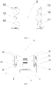
FIG. 3 is a schematic plan view of the centrifugal hypergravity vertical vibration table according to the present disclosure; -
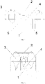
FIG. 4 is a schematic diagram of a table top guide system of the centrifugal hypergravity vertical vibration table according to the present disclosure; and -
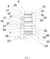
FIG. 5 is a schematic diagram of a vertical electro-hydraulic servo vibration excitation system with preload of the centrifugal hypergravity vertical vibration table according to the present disclosure. - Reference numerals: 1-a table base, 2-a table top, 3-an accumulator, 4-a vertical electro-hydraulic servo vibration excitation system with preload, 5-a table top guide system, 6-a vertical dynamic servo actuator, 7-a vertical static preloading actuator, 9-an actuating rod, 10-an upward preloading accumulator, 11-a downward preloading accumulator, 12-a dynamic actuating cylinder oil return accumulator, 13-a dynamic actuating cylinder oil supply accumulator, 14-a table top guide shaft, 15-a table top guide shaft bearing, 16-a guide shaft lower gasket, 17-a dynamic hydraulic servo valve, 18-a vertical actuating hydraulic interface channel, 19-an upper sealing ring, 20-an upper cavity sealing ring, 21-an isolation sealing ring, 22-a lower sealing ring, 23-a lower static servo valve, 24-an upper flange, 25-a middle flange, 26-a lower flange, 27-a downward preloading hydraulic interface channel, 28-an upward preloading hydraulic interface channel, 29-an actuating cylinder upper gasket, 30-an upper static servo valve, 31-a dynamic annular chamber, 32-a static upper annular chamber, and 33-a static lower circular chamber.
- The present disclosure is described in more detail hereinafter with reference to the accompanying drawings and specific embodiments.
- As shown in
FIG. 1 and FIG. 2 , a structure of specific implementations includes a table base and a table top, a vertical electro-hydraulic servo vibration excitation system with preload, a table top guide system, and an accumulator that are disposed on the table base. The table top has a flat top surface, is used to connect a test piece and the vibration excitation system, can reliably transmit an excitation force of the vibration table to the test piece, and is also suitable for the installation and fixation of a variety of different test pieces. In the specific implementation, screw holes for connection with a bottom plate of a hanging basket of a hypergravity centrifuge are formed in the table base, such that the table base is disposed in the hanging basket of the hypergravity centrifuge. - As shown in
FIG. 4 , the table top guide system is disposed between the table base and the table top, and is fixedly connected to the table base and the table top, and is mainly to balance the table top and guide the direction. The table top guide system includes a sleeve base, a table top guide shaft, a table top guide shaft bearing, and a guide shaft lower gasket. The vertically arranged table top guide shaft is fixedly disposed at four corners of a bottom of the table top. The table top guide shaft is sleeved on the sleeve base through the table top guide shaft bearing. A bottom of the sleeve base is fixed on the table base. The guide shaft lower gasket is connected between the table top guide shaft bearing and an inner bottom of the sleeve base for support. - The vibration excitation system and the table top guide system are arranged symmetrically, and the accumulator is reasonably arranged according to the weight, such that the center of gravity is located in the middle of the vibration table to solve the eccentricity problem of the whole hanging basket after installing the vibration table and avoid additional bending moment to the rotating arm of the centrifuge.
- Preferably, the table top adopts a high-strength alloy welding structure, and the static stiffness of the table top is improved by optimizing the rib layout of the table top and the local rigidity of the connecting parts to achieve light weight and high stiffness of the table top, thereby reducing the load of the actuator and bearing large load force at the same time.
- As shown in
FIG. 3 , the accumulator includes an upward preloading accumulator, a downward preloading accumulator, a dynamic actuating cylinder oil return accumulator, and a dynamic actuating cylinder oil supply accumulator that are disposed on the table top. - The upward preloading accumulator, the downward preloading accumulator, the dynamic actuating cylinder oil return accumulator, and the dynamic actuating cylinder oil supply accumulator are disposed on the table top.
- The specific implementation of the accumulator includes three upward preloading accumulators, one downward preloading accumulator, one dynamic actuating cylinder oil return accumulator, and one dynamic actuating cylinder oil supply accumulator.
- As shown in
FIG. 5 , the vertical electro-hydraulic servo vibration excitation system with preload includes a vertical dynamic servo actuator and a vertical static preloading actuator that are arranged up and down coaxially, and the two actuators share one set of rigid body and actuating rod. The vertical dynamic servo actuator includes a dynamic actuator sleeve. The vertical static preloading actuator includes a static actuator sleeve. A lower end of the static actuator sleeve is fixed to the table top. A lower end of the dynamic actuator sleeve is fixedly sleeved on an upper end of the static actuator sleeve coaxially. An actuating rod is disposed in both the static actuator sleeve and the dynamic actuator sleeve. A hydrostatic support bearing is disposed at an end of the actuating rod. An upper part of the actuating rod is nested in the dynamic actuator sleeve, and a lower part of the actuating rod is nested in the static actuator sleeve. An upper end of the actuating rod abuts against a center of a bottom surface of the table top. - Three flanges arranged at intervals are formed in an outer circumference of the actuating rod from top to bottom in an axial direction, and are respectively an upper flange, a middle flange, and a lower flange from top to bottom. An outer circumference of the upper flange is sealedly nested and connected in an inner wall of the dynamic actuator sleeve via an upper sealing ring. An outer circumference of the middle flange is sealedly nested and connected in the inner wall of the dynamic actuator sleeve via an upper cavity sealing ring. An outer circumference of the lower flange is sealedly nested and connected in an inner wall of the static actuator sleeve via a lower sealing ring. An inner flange is formed in the static actuator sleeve between the middle flange and the lower flange. An inner wall of the inner flange and the outer circumference of the actuating rod are sealedly nested and connected via an isolation sealing ring. An annular gap is formed between the outer circumference of the actuating rod between the upper flange and the middle flange and the inner wall of the dynamic actuator sleeve to form a dynamic upper annular chamber. An annular gap is formed between the outer circumference of the actuating rod between the middle flange and the lower flange and a nested portion of the inner walls of the dynamic actuator sleeve and the static actuator sleeve to form a middle annular chamber. The middle annular chamber is divided into a dynamic lower annular chamber located at an upper part and a static upper annular chamber located at a lower part by the flexible isolation sealing ring. An annular gap is formed between the outer circumference of the actuating rod below the lower flange and the inner wall of the static actuator sleeve to form a static lower circular chamber. The dynamic upper annular chamber and the dynamic lower annular chamber are separately connected to a dynamic hydraulic servo valve through respective vertical actuating hydraulic interface channels of the dynamic upper annular chamber and the dynamic lower annular chamber formed inside the dynamic actuator sleeve, and the dynamic hydraulic servo valve is connected to the dynamic actuating cylinder oil return accumulator and the dynamic actuating cylinder oil supply accumulator. The static upper annular chamber is connected to an upper static servo valve through a downward preloading hydraulic interface channel formed inside the static actuator sleeve, and the upper static servo valve is connected to the downward preloading accumulator. The static lower circular chamber is connected to a lower static servo valve through an upward preloading hydraulic interface channel formed inside the static actuator sleeve, and the lower static servo valve is connected to the upward preloading accumulator.
- The vertical dynamic servo actuator is used for high frequency dynamic actuation, and the vertical static preloading actuator is used for static and large load-bearing actuation.
- An actuating cylinder upper gasket is disposed in an upper end face of the dynamic actuator sleeve, and is used to assist in buffering and bearing the force between the upper end of the actuating rod and the bottom surface of the table top.
- In the specific implementation, both the upper flange and the lower flange are provided with outwardly convex flanges as piston rings to increase the effective piston area of the actuating rod.
- The oil of the vertical static preloading actuator is provided by the accumulator. The downward preloading hydraulic interface channel and the upward preloading hydraulic interface channel are respectively connected to the upward preloading accumulator and the downward preloading accumulator through an external hose for the servo valve. The vertical actuating hydraulic interface channel is connected to the dynamic actuating cylinder oil return accumulator and the dynamic actuating cylinder oil supply accumulator through the hose for the dynamic hydraulic servo valve. The dynamic hydraulic servo valve controls the motion of the vertical dynamic actuating cylinder through controlling the flow to the actuator.
- The hydraulic oil supply of the vertical static preloading actuator is connected to a plurality of large-capacity upward preloading accumulators. The capacity of the upward preloading accumulator is greater than that of the downward preloading accumulator, dynamic actuating cylinder oil return accumulator, and the dynamic actuating cylinder oil supply accumulator to allow free flow with minimal pressure loss during dynamic motion of the actuating rod.
- The static pressure between the vertical static preloading actuator and the accumulator is regulated by a servo valve. In the acceleration process of the centrifuge, the control program collects the centrifugal acceleration from the tachometer, calculates the corresponding control voltage, and sends it to the servo valve through the digital-to-analog conversion module to control the pressure of the static cylinder to control the output force of the cylinder.
- The dynamic force of the bidirectional up and down vibration of the actuating rod is generated by the pressure difference between the annular stepped surfaces on upper and lower sides of the flange. The servo valve controls the motion of the vertical dynamic actuating cylinder by controlling the flow to the actuator.
- The dynamic hydraulic servo valve is a flow distribution control valve. Through control of the dynamic hydraulic servo valve, the dynamic upper annular chamber and the dynamic lower annular chamber are uniformly adjusted to be fed and discharged from the dynamic actuating cylinder oil return accumulator and the dynamic actuating cylinder oil supply accumulator, such that oil pressure in the dynamic upper annular chamber and the dynamic lower annular chamber is applied to annular stepped surfaces on two sides of the middle flange to drive the actuating rod to act.
- Through control of the dynamic hydraulic servo valve, the static upper annular chamber is adjusted to be fed and discharged from the downward preloading accumulator, and the static lower circular chamber is adjusted to be fed and discharged from the upward preloading accumulator, such that oil pressure in the static upper annular chamber and the static lower circular chamber is applied to annular stepped surfaces on two sides of the lower flange to drive the actuating rod to act.
- Specifically, if the oil pressure in the dynamic upper annular chamber is greater than the oil pressure in the dynamic lower annular chamber, the middle flange is driven to move downward through the transmission by the annular stepped surfaces on two sides of the middle flange, otherwise, the middle flange is driven to move upward.
- If the oil pressure in the static upper annular chamber is greater than the oil pressure in the static lower circular chamber, the lower flange is driven to move downward through the transmission by the annular stepped surfaces on two sides of the lower flange, otherwise, the lower flange is driven to move upward.
- The oil pressure acting on the steps of the middle flange and the lower flange is combined to drive the actuating rod to act upward or downward as a whole, realizing the vibration actuation balance under hypergravity, improving the stability, and preventing failure.
- The vibration excitation method of the hypergravity field vertical vibration table of the present disclosure is specifically as follows.
- Static preload and a dynamic drive system are separated. Before the operation of the hypergravity centrifuge, through the control of the lower
static servo valve 23, the upward preloading hydraulic interface channel of the vertical static preloading actuator is driven to apply constant oil pressure to the static lower circular chamber to generate an upward preload to lift up the table top and maintain it. Accordingly, through the upperstatic servo valve 30, corresponding oil pressure is applied to the static upper annular chamber through the downward preloadinghydraulic interface channel 27 to generate a downward preload to apply the downward pressure force to the table top to maintain the balance. - The dynamic system is realized under static preload. When the hypergravity centrifuge starts to operate, with the continuous increase of centrifugal acceleration, the hypergravity of the table top gradually increases, the downward preload gradually decreases, and the upward preload increases in proportion to the centrifugal force acting on the movable mass. Due to the large area of the acting rod that provides the upward preload and the large capacity of the accumulator, its accuracy is affected, especially when the rotational speed of the centrifuge is relatively low, the centrifugal acceleration of the movable mass is small, and it is difficult to accurately balance the centrifugal force of the movable mass. The downward
static preloading accumulator 11 is used to directly apply oil pressure to the static lower circular chamber to provide a downward preload and ensure that the centrifugal force of the movable mass is balanced with the upward preload and the downward preload at any rotational speed of the centrifuge, such that the dynamic hydraulic servo valve is kept near the zero position. - When the hypergravity centrifuge reaches the target speed, the dynamic actuating cylinder
oil return accumulator 12 and the dynamic actuating cylinderoil supply accumulator 13 are controlled by the dynamichydraulic servo valve 17 to apply dynamic oil pressure to the dynamic annular chamber through the vertical actuatinghydraulic interface channel 18 to generate vertical vibration excitation for modelling the ground motion. Since the piston displacement of the vertical dynamic servo actuator is generally only 5 mm at the maximum, while the upward preloading hydraulic interface channel is connected by a large-diameter oil tube to a large-capacity accumulator, the oil pressure fluctuation of the static annular chamber is very small, and the force provided by the vertical static preloading actuator remains basically unchanged. - In this way, the static preload and the dynamic drive system are separated, and the vertical dynamic servo actuator does not need to balance the centrifugal force of the movable mass, such that the flow rate of the dynamic hydraulic servo valve is small, which ensures the frequency response characteristics of the servo valve and can realize high frequency vibration excitation.
- Therefore, in this way, the present disclosure can greatly reduce the vibration loading difficulty in the centrifugal hypergravity direction, and secure the control accuracy of modelling vertical ground motion under centrifugal hypergravity.
Claims (8)
- A centrifugal hypergravity vertical vibration table, comprising a table base (1) and a table top (2), a vertical electro-hydraulic servo vibration excitation system (4) with preload, a table top guide system (5), and an accumulator (3) that are disposed on the table base (1), wherein the table top guide system (5) comprises a sleeve base, a table top guide shaft (14), and a table top guide shaft bearing (15); the table top guide shaft (14) is fixedly disposed at a bottom of the table top (2), the table top guide shaft (14) is sleeved on the sleeve base through the table top guide shaft bearing (15), and a bottom of the sleeve base is fixed on the table base (1).
- The centrifugal hypergravity vertical vibration table according to claim 1, whereinthe accumulator (3) comprises an upward preloading accumulator (10), a downward preloading accumulator (11), a dynamic actuating cylinder oil return accumulator (12), and a dynamic actuating cylinder oil supply accumulator (13) that are disposed on the table top (2);the vertical electro-hydraulic servo vibration excitation system (4) with preload comprises a vertical dynamic servo actuator (6) and a vertical static preloading actuator (7) that are arranged up and down coaxially, the vertical dynamic servo actuator (6) comprises a dynamic actuator sleeve, the vertical static preloading actuator (7) comprises a static actuator sleeve, a lower end of the static actuator sleeve is fixed to the table top (2), a lower end of the dynamic actuator sleeve is fixedly sleeved on an upper end of the static actuator sleeve coaxially, an actuating rod (9) is disposed in both the static actuator sleeve and the dynamic actuator sleeve, and an upper end of the actuating rod (9) abuts against a center of a bottom surface of the table top (2); andthree flanges are formed in an outer circumference of the actuating rod (9) from top to bottom in an axial direction, and are respectively an upper flange (24), a middle flange (25), and a lower flange (26) from top to bottom, an outer circumference of the upper flange (24) is sealedly nested and connected in an inner wall of the dynamic actuator sleeve via an upper sealing ring (19), an outer circumference of the middle flange (25) is sealedly nested and connected in the inner wall of the dynamic actuator sleeve via an upper cavity sealing ring (20), an outer circumference of the lower flange (26) is sealedly nested and connected in an inner wall of the static actuator sleeve via a lower sealing ring (22), an inner flange is formed in the static actuator sleeve between the middle flange (25) and the lower flange (26), and an inner wall of the inner flange and the outer circumference of the actuating rod (9) are sealedly nested and connected via an isolation sealing ring (21); a dynamic upper annular chamber is formed between the outer circumference of the actuating rod (9) between the upper flange (24) and the middle flange (25) and the inner wall of the dynamic actuator sleeve, a middle annular chamber is formed between the outer circumference of the actuating rod (9) between the middle flange (25) and the lower flange (26) and a nested portion of the inner walls of the dynamic actuator sleeve and the static actuator sleeve, the middle annular chamber is divided into a dynamic lower annular chamber located at an upper part and a static upper annular chamber located at a lower part by the isolation sealing ring (21), and a static lower circular chamber is formed between the outer circumference of the actuating rod (9) below the lower flange (26) and the inner wall of the static actuator sleeve; the dynamic upper annular chamber and the dynamic lower annular chamber are separately connected to a dynamic hydraulic servo valve (17) through respective vertical actuating hydraulic interface channels (18) of the dynamic upper annular chamber and the dynamic lower annular chamber, and the dynamic hydraulic servo valve (17) is connected to the dynamic actuating cylinder oil return accumulator (12) and the dynamic actuating cylinder oil supply accumulator (13); the static upper annular chamber is connected to an upper static servo valve (30) through a downward preloading hydraulic interface channel (27), and the upper static servo valve (30) is connected to the downward preloading accumulator (11); and the static lower circular chamber is connected to a lower static servo valve (23) through an upward preloading hydraulic interface channel (28), and the lower static servo valve (23) is connected to the upward preloading accumulator (10).
- The centrifugal hypergravity vertical vibration table according to claim 2, wherein
an actuating cylinder upper gasket (29) is disposed in an upper end face of the dynamic actuator sleeve. - The centrifugal hypergravity vertical vibration table according to claim 2, whereinthrough control of the dynamic hydraulic servo valve (17), the dynamic upper annular chamber and the dynamic lower annular chamber are adjusted to be fed and discharged from the dynamic actuating cylinder oil return accumulator (12) and the dynamic actuating cylinder oil supply accumulator (13), such that oil pressure in the dynamic upper annular chamber and the dynamic lower annular chamber is applied to annular stepped surfaces on two sides of the middle flange (25) to drive the actuating rod (9) to act; andthrough control of the dynamic hydraulic servo valve (17), the static upper annular chamber is adjusted to be fed and discharged from the downward preloading accumulator (11), and the static lower circular chamber is adjusted to be fed and discharged from the upward preloading accumulator (10), such that oil pressure in the static upper annular chamber and the static lower circular chamber is applied to annular stepped surfaces on two sides of the lower flange (26) to drive the actuating rod (9) to act.
- The centrifugal hypergravity vertical vibration table according to claim 1, wherein
screw holes for connection with a bottom plate of a hanging basket of a hypergravity centrifuge are formed in the table base (1), such that the table base (1) is disposed in the hanging basket of the hypergravity centrifuge. - The centrifugal hypergravity vertical vibration table according to claim 1, wherein
a hydrostatic support bearing is disposed at an end of the actuating rod (9). - The centrifugal hypergravity vertical vibration table according to claim 1, wherein
the accumulator (3) comprises three upward preloading accumulators (10), one downward preloading accumulator (11), one dynamic actuating cylinder oil return accumulator (12), and one dynamic actuating cylinder oil supply accumulator (13). - A use of a centrifugal hypergravity vertical vibration table according to claim 1, wherein the centrifugal hypergravity vertical vibration table is used for vibration in a direction of a centrifugal force in a hypergravity centrifuge.
Applications Claiming Priority (2)
| Application Number | Priority Date | Filing Date | Title |
|---|---|---|---|
| CN202011024011.5A CN112284659B (en) | 2020-09-25 | 2020-09-25 | A super-gravity vertical vibration table |
| PCT/CN2021/110270 WO2022062673A1 (en) | 2020-09-25 | 2021-08-03 | Supergravity vertical vibration table |
Publications (4)
| Publication Number | Publication Date |
|---|---|
| EP4024024A1 true EP4024024A1 (en) | 2022-07-06 |
| EP4024024A4 EP4024024A4 (en) | 2022-11-16 |
| EP4024024C0 EP4024024C0 (en) | 2023-06-07 |
| EP4024024B1 EP4024024B1 (en) | 2023-06-07 |
Family
ID=74421276
Family Applications (1)
| Application Number | Title | Priority Date | Filing Date |
|---|---|---|---|
| EP21870567.1A Active EP4024024B1 (en) | 2020-09-25 | 2021-08-03 | Supergravity vertical vibration table |
Country Status (4)
| Country | Link |
|---|---|
| EP (1) | EP4024024B1 (en) |
| JP (1) | JP7189645B2 (en) |
| CN (1) | CN112284659B (en) |
| WO (1) | WO2022062673A1 (en) |
Families Citing this family (12)
| Publication number | Priority date | Publication date | Assignee | Title |
|---|---|---|---|---|
| CN112284659B (en) * | 2020-09-25 | 2021-07-30 | 浙江大学 | A super-gravity vertical vibration table |
| CN114813174B (en) * | 2022-04-26 | 2023-01-13 | 浙江大学 | Rail transit train running load simulation system and method for supergravity environment |
| CN115076164B (en) * | 2022-05-13 | 2024-07-16 | 浙江大学高端装备研究院 | Test platform for centrifugal machine airborne hydraulic servo high-frequency earthquake simulation experiment |
| CN114969945A (en) * | 2022-06-20 | 2022-08-30 | 中国中元国际工程有限公司 | A Design Method of Enlarged Head Pile Foundation for Vibration Control of Large Shaking Table |
| CN115979560B (en) * | 2022-09-21 | 2026-05-22 | 中国中元国际工程有限公司 | Large vibrating table foundation vibration control method |
| CN116793622B (en) * | 2023-05-25 | 2026-07-21 | 中国工程物理研究院总体工程研究所 | Static force balancing device suitable for electric vibrating table and control method |
| CN116952758A (en) * | 2023-07-13 | 2023-10-27 | 同济大学 | Centrifugal vibration equipment for simulating passive pile end bearing arch effect under earthquake load |
| CN117825217B (en) * | 2023-12-28 | 2024-11-08 | 中国科学院空间应用工程与技术中心 | Particle movement driving experimental device |
| CN119827085B (en) * | 2025-01-08 | 2025-10-10 | 昆明理工大学 | Self-excitation vibration testing device |
| CN120831214B (en) * | 2025-09-19 | 2025-12-09 | 四川川矿索道工程有限责任公司 | Vibrating device for fatigue test of passenger ropeway suspended carriage |
| CN121389481B (en) * | 2025-10-28 | 2026-05-08 | 中建八局第一建设有限公司 | An intelligent seismic structural optimization design method and system for high-rise buildings |
| CN121540456B (en) * | 2025-11-20 | 2026-07-17 | 山东大学 | Gravity balance dislocation device capable of realizing vertical reciprocating motion of large-tonnage test system |
Family Cites Families (16)
| Publication number | Priority date | Publication date | Assignee | Title |
|---|---|---|---|---|
| JPS59155603A (en) * | 1983-02-23 | 1984-09-04 | Hitachi Ltd | Hydraulic driving apparatus |
| JPS60183072A (en) * | 1984-03-01 | 1985-09-18 | 株式会社振研 | Bidirectional vibrator |
| US7255008B2 (en) * | 2005-04-07 | 2007-08-14 | Imv Corporation | Vibration-testing system |
| CN102794235A (en) * | 2011-05-27 | 2012-11-28 | 中国水利水电科学研究院 | Vibrating table for centrifugal machine |
| CN103016453B (en) * | 2012-12-14 | 2015-02-04 | 浙江大学 | Impulse test system of hydraulic hose |
| CN104502210A (en) * | 2014-12-30 | 2015-04-08 | 天津福云天翼科技有限公司 | Centrifuge shaking table |
| CN204439479U (en) * | 2014-12-30 | 2015-07-01 | 天津福云天翼科技有限公司 | Hydro-extractor shaking table |
| CN204479256U (en) * | 2015-01-14 | 2015-07-15 | 中国矿业大学 | A kind of single table surface horizontal vertical vibration table |
| CN205449713U (en) * | 2016-02-29 | 2016-08-10 | 成都理工大学 | Centrifuge shaking table |
| CN207730415U (en) * | 2018-01-11 | 2018-08-14 | 中国工程物理研究院总体工程研究所 | A kind of super gravity field medium-high frequency high-thrust single degree of freedom horizontal vibration platform |
| CN108318201A (en) * | 2018-01-11 | 2018-07-24 | 中国工程物理研究院总体工程研究所 | A kind of super gravity field medium-high frequency high-thrust single degree of freedom horizontal vibration platform |
| CN108414177A (en) * | 2018-06-20 | 2018-08-17 | 中国工程物理研究院总体工程研究所 | The heavy load high frequency sound electrohydraulic servo oscillation device being operated under high centrifugal field |
| GB2574689B (en) * | 2019-01-04 | 2020-07-15 | Libertine Fpe Ltd | Linear electrical machine |
| CN111441081B (en) * | 2020-04-03 | 2023-10-27 | 浙江大学 | Centrifugal hypergravity casting and directional solidification system |
| CN111595692B (en) * | 2020-04-03 | 2024-12-31 | 浙江大学 | Cantilever centrifugal ultragravity experimental device for material preparation and performance testing |
| CN112284659B (en) * | 2020-09-25 | 2021-07-30 | 浙江大学 | A super-gravity vertical vibration table |
-
2020
- 2020-09-25 CN CN202011024011.5A patent/CN112284659B/en active Active
-
2021
- 2021-08-03 EP EP21870567.1A patent/EP4024024B1/en active Active
- 2021-08-03 WO PCT/CN2021/110270 patent/WO2022062673A1/en not_active Ceased
- 2021-08-03 JP JP2022525550A patent/JP7189645B2/en active Active
Also Published As
| Publication number | Publication date |
|---|---|
| JP7189645B2 (en) | 2022-12-14 |
| CN112284659B (en) | 2021-07-30 |
| EP4024024C0 (en) | 2023-06-07 |
| EP4024024A4 (en) | 2022-11-16 |
| JP2022546876A (en) | 2022-11-09 |
| CN112284659A (en) | 2021-01-29 |
| EP4024024B1 (en) | 2023-06-07 |
| WO2022062673A1 (en) | 2022-03-31 |
Similar Documents
| Publication | Publication Date | Title |
|---|---|---|
| EP4024024B1 (en) | Supergravity vertical vibration table | |
| US20180031457A1 (en) | Shear test device and test method of rock mass discontinuities under constant normal stiffness condition | |
| Shen et al. | Review of the energy saving hydraulic system based on common pressure rail | |
| CN111780938B (en) | Three-way vibration table of centrifugal machine | |
| Song et al. | A new structural-dynamics module for offshore multimember substructures within the wind turbine computer-aided engineering tool FAST | |
| CN102794235A (en) | Vibrating table for centrifugal machine | |
| Qiao et al. | Design and characteristic research of a novel electromechanical-hydraulic hybrid actuator with two transmission mechanisms | |
| Guo et al. | Facility performance indexes and rapid test feasibility evaluation method of shaking tables | |
| CN108731894A (en) | A kind of structure for eliminating underwater shake table waterproof perturbation wave | |
| CN108318201A (en) | A kind of super gravity field medium-high frequency high-thrust single degree of freedom horizontal vibration platform | |
| CN106324501A (en) | Electric motor loading test platform for reproducing six freedom degree load of wind machine and electric motor loading strategy | |
| Schaumann et al. | Numerical investigations on local degradation and vertical misalignments of grouted joints in monopile foundations | |
| Liu et al. | Failure envelopes of wide-shallow composite bucket foundation for offshore wind turbines in silty sand | |
| Fenglin et al. | The relationship between eccentric structure and super-lift device of all-terrain crane based on the overall stability | |
| Severn et al. | The contribution of shaking tables to earthquake engineering | |
| CN212300771U (en) | One-way shaking table of centrifuge | |
| CN207730415U (en) | A kind of super gravity field medium-high frequency high-thrust single degree of freedom horizontal vibration platform | |
| Lou et al. | Research on the Synchronization and Shock Characteristics of an Air Adjustment Mechanism for Cluster‐Type DTH Hammers under Partial Loads | |
| US11867207B2 (en) | Electro-hydraulic servo actuator capable of implementing long-stroke and high-frequency loading, and control method | |
| CN208333797U (en) | A kind of structure for eliminating underwater shake table waterproof perturbation wave | |
| CN202577376U (en) | Four dimensional manipulator for high g value geotechnical centrifuge test | |
| RU2184811C1 (en) | Hydraulic pile-driving hammer | |
| CN201848724U (en) | Multifunctional mechanical hydraulic balance device | |
| CN121539538A (en) | Test methods and systems for heavy-duty, low-friction hydraulic actuators used in rock brittle fracture. | |
| CN112986026B (en) | Rock high-frequency high-load cyclic dynamic load test device and test method |
Legal Events
| Date | Code | Title | Description |
|---|---|---|---|
| STAA | Information on the status of an ep patent application or granted ep patent |
Free format text: STATUS: THE INTERNATIONAL PUBLICATION HAS BEEN MADE |
|
| PUAI | Public reference made under article 153(3) epc to a published international application that has entered the european phase |
Free format text: ORIGINAL CODE: 0009012 |
|
| STAA | Information on the status of an ep patent application or granted ep patent |
Free format text: STATUS: REQUEST FOR EXAMINATION WAS MADE |
|
| 17P | Request for examination filed |
Effective date: 20220331 |
|
| AK | Designated contracting states |
Kind code of ref document: A1 Designated state(s): AL AT BE BG CH CY CZ DE DK EE ES FI FR GB GR HR HU IE IS IT LI LT LU LV MC MK MT NL NO PL PT RO RS SE SI SK SM TR |
|
| A4 | Supplementary search report drawn up and despatched |
Effective date: 20221014 |
|
| RIC1 | Information provided on ipc code assigned before grant |
Ipc: B04B 5/10 20060101ALI20221010BHEP Ipc: G01M 7/04 20060101ALI20221010BHEP Ipc: G01M 7/02 20060101AFI20221010BHEP |
|
| GRAP | Despatch of communication of intention to grant a patent |
Free format text: ORIGINAL CODE: EPIDOSNIGR1 |
|
| STAA | Information on the status of an ep patent application or granted ep patent |
Free format text: STATUS: GRANT OF PATENT IS INTENDED |
|
| RIC1 | Information provided on ipc code assigned before grant |
Ipc: B04B 5/10 19680901ALI20230112BHEP Ipc: G01M 7/04 19900101ALI20230112BHEP Ipc: G01M 7/02 19900101AFI20230112BHEP |
|
| DAV | Request for validation of the european patent (deleted) | ||
| DAX | Request for extension of the european patent (deleted) | ||
| INTG | Intention to grant announced |
Effective date: 20230126 |
|
| GRAS | Grant fee paid |
Free format text: ORIGINAL CODE: EPIDOSNIGR3 |
|
| GRAA | (expected) grant |
Free format text: ORIGINAL CODE: 0009210 |
|
| STAA | Information on the status of an ep patent application or granted ep patent |
Free format text: STATUS: THE PATENT HAS BEEN GRANTED |
|
| AK | Designated contracting states |
Kind code of ref document: B1 Designated state(s): AL AT BE BG CH CY CZ DE DK EE ES FI FR GB GR HR HU IE IS IT LI LT LU LV MC MK MT NL NO PL PT RO RS SE SI SK SM TR |
|
| REG | Reference to a national code |
Ref country code: GB Ref legal event code: FG4D |
|
| REG | Reference to a national code |
Ref country code: CH Ref legal event code: EP Ref country code: AT Ref legal event code: REF Ref document number: 1576463 Country of ref document: AT Kind code of ref document: T Effective date: 20230615 |
|
| REG | Reference to a national code |
Ref country code: DE Ref legal event code: R096 Ref document number: 602021002864 Country of ref document: DE |
|
| U01 | Request for unitary effect filed |
Effective date: 20230612 |
|
| U07 | Unitary effect registered |
Designated state(s): AT BE BG DE DK EE FI FR IT LT LU LV MT NL PT SE SI Effective date: 20230620 |
|
| REG | Reference to a national code |
Ref country code: LT Ref legal event code: MG9D |
|
| U20 | Renewal fee for the european patent with unitary effect paid |
Year of fee payment: 3 Effective date: 20230829 |
|
| PG25 | Lapsed in a contracting state [announced via postgrant information from national office to epo] |
Ref country code: NO Free format text: LAPSE BECAUSE OF FAILURE TO SUBMIT A TRANSLATION OF THE DESCRIPTION OR TO PAY THE FEE WITHIN THE PRESCRIBED TIME-LIMIT Effective date: 20230907 Ref country code: ES Free format text: LAPSE BECAUSE OF FAILURE TO SUBMIT A TRANSLATION OF THE DESCRIPTION OR TO PAY THE FEE WITHIN THE PRESCRIBED TIME-LIMIT Effective date: 20230607 |
|
| PG25 | Lapsed in a contracting state [announced via postgrant information from national office to epo] |
Ref country code: RS Free format text: LAPSE BECAUSE OF FAILURE TO SUBMIT A TRANSLATION OF THE DESCRIPTION OR TO PAY THE FEE WITHIN THE PRESCRIBED TIME-LIMIT Effective date: 20230607 Ref country code: HR Free format text: LAPSE BECAUSE OF FAILURE TO SUBMIT A TRANSLATION OF THE DESCRIPTION OR TO PAY THE FEE WITHIN THE PRESCRIBED TIME-LIMIT Effective date: 20230607 Ref country code: GR Free format text: LAPSE BECAUSE OF FAILURE TO SUBMIT A TRANSLATION OF THE DESCRIPTION OR TO PAY THE FEE WITHIN THE PRESCRIBED TIME-LIMIT Effective date: 20230908 |
|
| PG25 | Lapsed in a contracting state [announced via postgrant information from national office to epo] |
Ref country code: SK Free format text: LAPSE BECAUSE OF FAILURE TO SUBMIT A TRANSLATION OF THE DESCRIPTION OR TO PAY THE FEE WITHIN THE PRESCRIBED TIME-LIMIT Effective date: 20230607 |
|
| PG25 | Lapsed in a contracting state [announced via postgrant information from national office to epo] |
Ref country code: IS Free format text: LAPSE BECAUSE OF FAILURE TO SUBMIT A TRANSLATION OF THE DESCRIPTION OR TO PAY THE FEE WITHIN THE PRESCRIBED TIME-LIMIT Effective date: 20231007 |
|
| PG25 | Lapsed in a contracting state [announced via postgrant information from national office to epo] |
Ref country code: SM Free format text: LAPSE BECAUSE OF FAILURE TO SUBMIT A TRANSLATION OF THE DESCRIPTION OR TO PAY THE FEE WITHIN THE PRESCRIBED TIME-LIMIT Effective date: 20230607 Ref country code: SK Free format text: LAPSE BECAUSE OF FAILURE TO SUBMIT A TRANSLATION OF THE DESCRIPTION OR TO PAY THE FEE WITHIN THE PRESCRIBED TIME-LIMIT Effective date: 20230607 Ref country code: RO Free format text: LAPSE BECAUSE OF FAILURE TO SUBMIT A TRANSLATION OF THE DESCRIPTION OR TO PAY THE FEE WITHIN THE PRESCRIBED TIME-LIMIT Effective date: 20230607 Ref country code: IS Free format text: LAPSE BECAUSE OF FAILURE TO SUBMIT A TRANSLATION OF THE DESCRIPTION OR TO PAY THE FEE WITHIN THE PRESCRIBED TIME-LIMIT Effective date: 20231007 Ref country code: CZ Free format text: LAPSE BECAUSE OF FAILURE TO SUBMIT A TRANSLATION OF THE DESCRIPTION OR TO PAY THE FEE WITHIN THE PRESCRIBED TIME-LIMIT Effective date: 20230607 |
|
| PG25 | Lapsed in a contracting state [announced via postgrant information from national office to epo] |
Ref country code: PL Free format text: LAPSE BECAUSE OF FAILURE TO SUBMIT A TRANSLATION OF THE DESCRIPTION OR TO PAY THE FEE WITHIN THE PRESCRIBED TIME-LIMIT Effective date: 20230607 |
|
| REG | Reference to a national code |
Ref country code: DE Ref legal event code: R097 Ref document number: 602021002864 Country of ref document: DE |
|
| PG25 | Lapsed in a contracting state [announced via postgrant information from national office to epo] |
Ref country code: MC Free format text: LAPSE BECAUSE OF FAILURE TO SUBMIT A TRANSLATION OF THE DESCRIPTION OR TO PAY THE FEE WITHIN THE PRESCRIBED TIME-LIMIT Effective date: 20230607 |
|
| PG25 | Lapsed in a contracting state [announced via postgrant information from national office to epo] |
Ref country code: MC Free format text: LAPSE BECAUSE OF FAILURE TO SUBMIT A TRANSLATION OF THE DESCRIPTION OR TO PAY THE FEE WITHIN THE PRESCRIBED TIME-LIMIT Effective date: 20230607 |
|
| PLBE | No opposition filed within time limit |
Free format text: ORIGINAL CODE: 0009261 |
|
| STAA | Information on the status of an ep patent application or granted ep patent |
Free format text: STATUS: NO OPPOSITION FILED WITHIN TIME LIMIT |
|
| 26N | No opposition filed |
Effective date: 20240308 |
|
| REG | Reference to a national code |
Ref country code: IE Ref legal event code: MM4A |
|
| PG25 | Lapsed in a contracting state [announced via postgrant information from national office to epo] |
Ref country code: IE Free format text: LAPSE BECAUSE OF NON-PAYMENT OF DUE FEES Effective date: 20230803 |
|
| U20 | Renewal fee for the european patent with unitary effect paid |
Year of fee payment: 4 Effective date: 20240611 |
|
| PG25 | Lapsed in a contracting state [announced via postgrant information from national office to epo] |
Ref country code: IE Free format text: LAPSE BECAUSE OF NON-PAYMENT OF DUE FEES Effective date: 20230803 |
|
| REG | Reference to a national code |
Ref country code: CH Ref legal event code: PL |
|
| PG25 | Lapsed in a contracting state [announced via postgrant information from national office to epo] |
Ref country code: CH Free format text: LAPSE BECAUSE OF NON-PAYMENT OF DUE FEES Effective date: 20240831 |
|
| U20 | Renewal fee for the european patent with unitary effect paid |
Year of fee payment: 5 Effective date: 20250606 |
|
| PG25 | Lapsed in a contracting state [announced via postgrant information from national office to epo] |
Ref country code: CY Free format text: LAPSE BECAUSE OF FAILURE TO SUBMIT A TRANSLATION OF THE DESCRIPTION OR TO PAY THE FEE WITHIN THE PRESCRIBED TIME-LIMIT; INVALID AB INITIO Effective date: 20210803 |
|
| PG25 | Lapsed in a contracting state [announced via postgrant information from national office to epo] |
Ref country code: HU Free format text: LAPSE BECAUSE OF FAILURE TO SUBMIT A TRANSLATION OF THE DESCRIPTION OR TO PAY THE FEE WITHIN THE PRESCRIBED TIME-LIMIT; INVALID AB INITIO Effective date: 20210803 |
|
| PG25 | Lapsed in a contracting state [announced via postgrant information from national office to epo] |
Ref country code: TR Free format text: LAPSE BECAUSE OF FAILURE TO SUBMIT A TRANSLATION OF THE DESCRIPTION OR TO PAY THE FEE WITHIN THE PRESCRIBED TIME-LIMIT Effective date: 20230607 |
|
| GBPC | Gb: european patent ceased through non-payment of renewal fee |
Effective date: 20250803 |
|
| PG25 | Lapsed in a contracting state [announced via postgrant information from national office to epo] |
Ref country code: CH Free format text: THE PATENT HAS BEEN ANNULLED BY A DECISION OF A NATIONAL AUTHORITY Effective date: 20240831 |
|
| PG25 | Lapsed in a contracting state [announced via postgrant information from national office to epo] |
Ref country code: GB Free format text: LAPSE BECAUSE OF NON-PAYMENT OF DUE FEES Effective date: 20250803 |