EP4023950A1 - Mobile air conditioner - Google Patents
Mobile air conditioner Download PDFInfo
- Publication number
- EP4023950A1 EP4023950A1 EP20881276.8A EP20881276A EP4023950A1 EP 4023950 A1 EP4023950 A1 EP 4023950A1 EP 20881276 A EP20881276 A EP 20881276A EP 4023950 A1 EP4023950 A1 EP 4023950A1
- Authority
- EP
- European Patent Office
- Prior art keywords
- housing
- storage box
- air conditioner
- guide
- protrusion
- Prior art date
- Legal status (The legal status is an assumption and is not a legal conclusion. Google has not performed a legal analysis and makes no representation as to the accuracy of the status listed.)
- Pending
Links
Images













Classifications
-
- F—MECHANICAL ENGINEERING; LIGHTING; HEATING; WEAPONS; BLASTING
- F24—HEATING; RANGES; VENTILATING
- F24F—AIR-CONDITIONING; AIR-HUMIDIFICATION; VENTILATION; USE OF AIR CURRENTS FOR SCREENING
- F24F11/00—Control or safety arrangements
- F24F11/50—Control or safety arrangements characterised by user interfaces or communication
- F24F11/56—Remote control
-
- F—MECHANICAL ENGINEERING; LIGHTING; HEATING; WEAPONS; BLASTING
- F24—HEATING; RANGES; VENTILATING
- F24F—AIR-CONDITIONING; AIR-HUMIDIFICATION; VENTILATION; USE OF AIR CURRENTS FOR SCREENING
- F24F1/00—Room units for air-conditioning, e.g. separate or self-contained units or units receiving primary air from a central station
- F24F1/02—Self-contained room units for air-conditioning, i.e. with all apparatus for treatment installed in a common casing
- F24F1/04—Arrangements for portability
-
- F—MECHANICAL ENGINEERING; LIGHTING; HEATING; WEAPONS; BLASTING
- F24—HEATING; RANGES; VENTILATING
- F24F—AIR-CONDITIONING; AIR-HUMIDIFICATION; VENTILATION; USE OF AIR CURRENTS FOR SCREENING
- F24F11/00—Control or safety arrangements
- F24F11/89—Arrangement or mounting of control or safety devices
-
- F—MECHANICAL ENGINEERING; LIGHTING; HEATING; WEAPONS; BLASTING
- F24—HEATING; RANGES; VENTILATING
- F24F—AIR-CONDITIONING; AIR-HUMIDIFICATION; VENTILATION; USE OF AIR CURRENTS FOR SCREENING
- F24F13/00—Details common to, or for air-conditioning, air-humidification, ventilation or use of air currents for screening
- F24F13/20—Casings or covers
-
- F—MECHANICAL ENGINEERING; LIGHTING; HEATING; WEAPONS; BLASTING
- F24—HEATING; RANGES; VENTILATING
- F24F—AIR-CONDITIONING; AIR-HUMIDIFICATION; VENTILATION; USE OF AIR CURRENTS FOR SCREENING
- F24F13/00—Details common to, or for air-conditioning, air-humidification, ventilation or use of air currents for screening
- F24F13/20—Casings or covers
- F24F2013/207—Casings or covers with control knobs; Mounting controlling members or control units therein
Definitions
- the present disclosure relates to the field of air-conditioning, and in particular, to a mobile air conditioner.
- a mobile air conditioner is generally equipped with a remote control, which is usually stored separately.
- the separate storage of the remote control is unfavorable for product packaging and transportation, and in addition, tends to cause undesirable loss of the remote control during use.
- the main purpose of the present disclosure is to provide a mobile air conditioner, which aims to at least solve the technical problem of inconvenient storage of the remote control of the mobile air conditioner.
- a mobile air conditioner including:
- the storage box blocks the hidden opening in the second position.
- the storage box is rotatably provided on the housing, such that the storage box has the first position and the second position.
- a support protrusion is protruded on an inner wall surface of the housing, and the storage box is rotatably connected to the support protrusion, such that the storage box is rotatably provided on the housing.
- the two support protrusions are respectively provided on opposite sides of the hidden opening;
- the storage box is provided between the two support protrusions, and two sides of the storage box are respectively rotatably provided on the two support protrusions.
- a rotating shaft is protruded on the storage box, a rotating hole is provided on the support protrusion, the rotating shaft is rotatably disposed in the rotating hole, so that the storage box is rotatably connected to the support protrusion.
- the support protrusion is also provided with a guide groove in communication with the rotating hole, one end of the guide groove away from the rotating hole defines an opening, and the guide groove is configured to guide the rotating shaft to slide into the rotating hole.
- the guide groove is flared; and/or a connection between the guide groove on at least one of the support protrusions and the rotating hole is provided with a locking protrusion, and the locking protrusion is configured to limit the rotating shaft from the rotating hole.
- a thickening portion is provided on a side of the support protrusion facing away from the storage box, and the thickening portion is provided on a periphery of the rotating hole; and/or a protrusion is provided on a side of each support protrusion facing the storage box, and the protrusion is configured to abut against an outer wall surface of the storage box when the storage box is rotated.
- the storage box includes a first side wall covering the hidden opening in the second position, and two second side walls adjacent to the first side wall, an open end of the second side wall is formed with an avoidance notch at the connection with the first side wall, and the avoidance notch is configured to avoid an edge of the hidden opening when the storage box is rotated; or an open end of the storage box is inclined and configured to avoid the edge of the hidden opening when the storage box is rotated.
- a guide structure is provided on the storage box and the housing, and the guide structure is configured to guide the rotation of the storage box.
- an inner wall surface of the housing is provided protrudingly with a guide support portion
- the guide structure includes a guide protrusion laterally protruding from the guide support portion, and a guide groove provided on an outer wall surface of the storage box, and the guide protrusion is slidably provided in the guide groove, and is configured to guide the rotation of the storage box.
- a depth of the guide groove is increased from outside to inside; and/or the guide groove is an arc groove.
- the storage box and the housing are provided with a first limiting structure, and the first limiting structure is configured to limit the storage box and the housing in the second position; and/or the storage box and the housing are provided with a second limiting structure, and the second limiting structure is configured to limit the storage box and the housing in the first position.
- the second limiting structure includes a stop protrusion provided on the storage box, and the stop protrusion is provided in the housing, the stop protrusion is in contact with an inner wall surface of the housing in the first position, and is configured to limit the storage box.
- the stop protrusion is away from a rotation axis of the storage box; and/or the stop protrusion is rotatably provided on the storage box.
- an open end of a side wall of the storage box is formed with a gripping notch, and the gripping notch is recessed toward a bottom of the storage cavity.
- the gripping notch is configured to break a guide groove of the storage box to form two guide sub-grooves, and a fracture is formed between the two guide sub-grooves.
- the storage box includes a first side wall covering the hidden opening in the second position, the first side wall is provided with a gripping structure, and the gripping structure is configured for a user to grasp.
- the gripping structure includes a buckle hand formed by the inward concave of the first side wall;
- the gripping structure includes a buckle hand formed by the inward concave of the first side wall, the buckle handle has a buckle opening, the buckle handle includes a first buckle wall and a second buckle wall provided on opposite sides of the buckle opening, the first buckle wall extends away from the second buckle wall (in the direction of 2323) obliquely from the outside to the inside; and/or the second buckle wall extends from the outside to the inside to a direction close to the first buckle wall.
- guide ribs are protruded on an inner wall surface of the storage cavity, the guide ribs are extended along a depth direction of the storage cavity, a height of the guide ribs is increased in a direction from the storage opening to a bottom of the storage cavity; and/or a width of the guide ribs is increased in the direction from the storage opening to the bottom of the storage cavity.
- the storage box is slidably provided in the housing, and is configured such that the storage box has the first position and the second position.
- a hidden opening is provided on the housing, and the storage box can be hidden in the housing through the hidden opening, so that the remote control can be hidden/stored in the housing.
- hiding the storage box in the housing can not only reduce the risk of damage to the storage box and the remote control, but also avoid damage to the appearance of the housing (i.e., the mobile air conditioner), thereby improving user comfort.
- a and/or B includes only A, or only B, or both A and B.
- the present disclosure provides a mobile air conditioner.
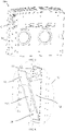
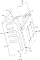
- the mobile air conditioner 100 includes a housing 10 and a storage box 20.
- the storage box 20 includes a storage cavity 21 and a storage opening 22 in communication with the storage cavity 21.
- the storage cavity 21 is usually used for accommodating the remote controller.
- the remote controller can be stored in the storage cavity 21 through the storage opening 22, or can be separated from the storage cavity 21 through the storage opening 22.
- the storage opening 22 can also be used to store other items, such as mobile phones, antiseptics, and air stimulants.
- the housing 10 is provided with a hidden opening 11.
- the hidden opening 11 penetrates the wall of housing 10.
- the storage box 20 is movably disposed on the housing 10, and the storage box 20 has a first position extending out of the hidden opening 11 to expose the storage opening 22, and a second position hidden in the housing 10.
- the storage box 20 is movably provided at the hidden opening 11.
- the storage box 20 can be rotatably provided on the housing 10; alternatively, the storage box 20 can be slidably provided on the housing 10; alternatively, the storage box 20 is detachably provided on the housing 10, and so on. As a result, the storage box 20 is movably provided on the housing 10.
- the storage box 20 (the side wall) blocks the hidden opening 11 or the storage box 20 is completely moved into the housing 10, so that the storage box 20 is hidden in the housing 10.
- the storage box 20 when it is necessary to store or pack the mobile air conditioner 100, the storage box 20 can be moved to the first position first, so that (the open end or the whole of the storage box 20) extends out of the hidden opening 11 and exposes the storage opening 22, so that the remote control can be stored in the storage box 20. Subsequently, the storage box 20 is moved to the second position to hide the storage box 20 in the housing 10, so that the remote controller is hidden/stored in the housing 10. In this way, hiding the storage box 20 in the housing 10 can reduce the risk of the storage box 20 being collided during transportation, so as to reduce the risk of damage to the storage box 20.
- the risk of collision/interference between the storage box 20 and the user can be reduced, thereby not only reducing the risk of damage to the storage box 20, but also improving the user comfort.
- the storage box 20 can be moved to the first position for the user to take the remote controller.
- a hidden opening 11 is provided on the housing 10, and the storage box 20 can be hidden in the housing 10 through the hidden opening 11, so that the remote control can be hidden/stored in the housing 10.
- hiding the storage box 20 in the housing 10 can not only reduce the risk of damage to the storage box 20 and the remote control, but also avoid damage to the appearance of the housing 10 (i.e., the mobile air conditioner 100), thereby improving user comfort.
- a switch door can be provided at the hidden opening 11 to close/cover the hidden opening 11 when the storage box 20 is in the second position.
- the switch door is slidably arranged on the inner wall surface of the housing 10 to close or open the hidden opening 11.
- an escape chute is formed on the inner wall surface of the housing 10, and the switch door is slidably provided in the escape chute. In this way, not only can the storage box 20 be limited to prevent it from slipping out of the hidden opening 11, but also the integrity of the housing 10 can be improved to ensure the appearance of the housing 10 and the mobile air conditioner 100.
- a storage cavity can be provided on the inner wall surface of the housing 10 corresponding to the hidden opening 11 to accommodate the storage box 20.
- the storage box 20 blocks the hidden opening 11.
- the box wall of the storage box 20 blocks the hidden opening 11.
- the storage box 20 includes a first side wall 23, and when in the second position, the first side wall 23 covers the hidden opening 11. In this way, the hidden opening 11 can be covered by the structure of the storage box 20 itself, so that the structure of the mobile air conditioner 100 can be simplified.
- the outer wall surface of the first side wall 23 is flush with or approximately flush with the outer wall surface of the housing 10; in this way, the risk of collision of the storage box 20 can be further reduced, and the aesthetics of the housing 10 can also be improved.
- the housing 10 is in the shape of a cuboid or substantially in the shape of a cuboid.
- the housing 10 includes a bottom plate, a top housing (i.e., a top plate) opposite to the bottom plate, and an enclosure.
- the enclosure has a front housing wall, a rear housing wall, a left housing wall and a right housing wall.
- the enclosure includes a front housing and a rear housing, and the front housing and the rear housing are enclosed to form an enclosure.
- the hidden opening 11 can be provided on the top housing (i.e., the top plate) or the enclosure.
- the hidden opening 11 is provided on the left housing wall or the right housing wall, and the hidden opening 11 can be provided on the front housing or the rear housing.
- the length direction of the storage box 20 is parallel or substantially parallel to the housing wall where the hidden opening 11 is located.
- the storage box 20 is in the shape of a cuboid or substantially in the shape of a cuboid; the storage box 20 is vertically arranged in the second position.
- a reinforcing ring protrusion 12 is formed on the inner wall surface of the housing 10, and the reinforcing ring protrusion 12 is arranged on the periphery of the hidden opening 11. In this way, not only the structural strength of the housing wall at the hidden opening 11 can be enhanced, but also the risk of damage to the housing 10 at the hidden opening 11 can be reduced. It is also convenient to provide a structure matching with the storage box 20 on the housing 10.
- the reinforcing ring protrusion can be formed by folding the periphery of the hidden opening 11 inward.
- the reinforcing ring protrusion is in the shape of a plate or a sheet.
- the storage box 20 and the housing 10 are provided with a first limiting structure, and the first limiting structure is used to limit the storage box 20 and the housing 10 in the second position. In this way, the storage box 20 can be prevented from moving too much and the storage box 20 is positioned at the second position, and the storage box 20 can also be prevented from being buckled/sunk into the housing 10.
- the first limiting structure there are multiple forms of the first limiting structure, including but not limited to one or more of a magnetic attraction structure, a snap-fit structure, and a stop structure, etc., which will be described with examples below.
- the first limiting structure includes a first blocking protrusion 231 provided on the storage box 20 and a second blocking protrusion 121 provided on the inner wall surface of the housing 10.
- the second blocking protrusion 121 protrudes toward the center of the hidden opening 11. In the second position, the first blocking protrusion 231 abuts the second blocking protrusion 121 to limit the storage box 20 and prevent its excessive movement.
- the first side wall 23 protrudes from the other side walls (including the second side wall 24) to form a first blocking protrusion 231.
- the second blocking protrusion 121 can be protruded on the inner (ring) surface of the reinforcing ring protrusion.
- the second blocking protrusion 121 extends along the side edge of the hidden opening 11.
- the inner side (ring) surface of the reinforcing ring protrusion is further provided with a reinforcing rib (not shown) connecting the second blocking protrusion 121 and the reinforcing ring protrusion.
- the first blocking protrusion 231 can also cooperate with other structures, for example, the hidden opening 11 is a stepped hole.
- the storage box 20 and the housing 10 are provided with a second limiting structure, and the second limiting structure is used to limit the storage box 20 and the housing 10 in the first position. In this way, excessive movement of the storage box 20 can be prevented, so that the storage box 20 is positioned in the first position, so as to prevent the storage box 20 from being separated from the housing 10.
- the second limiting structure may not be provided, and the storage box 20 can be taken out from the hidden opening 11 when necessary (using a remote controller).
- the second limiting structure there are many forms of the second limiting structure, including but not limited to one or more of a magnetic attraction structure, a buckle structure, and a stop structure, etc.
- a magnetic attraction structure for example, a magnetode
- a buckle structure for example, a buckle
- a stop structure for example, a stop structure
- the first limiting structure and the second limiting structure may share a part of the structure.
- the storage box 20 is rotatably disposed in the hidden opening 11 so that the storage box 20 has a first position and a second position.
- the storage box 20 can be driven to rotate to the first position, so that the open end of the storage box 20 extends out of the hidden opening 11 to expose the storage opening 22.
- the remote control is taken out or the storage box 20 is put into the storage cavity 21.
- the storage box 20 can be driven to rotate to the second position, so that the storage box 20 is hidden from the housing 10.
- the rotation of the storage box 20 requires less space for operation, which is beneficial to saving the internal space of the housing 10.
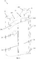
- the inner wall surface of the housing 10 is provided protrudingly with a support protrusion 13.
- the support protrusion 13 extends away from the housing wall where the hidden opening 11 is located, and the storage box 20 is rotatably connected to the support protrusion 13, so that the storage box 20 is rotatably disposed on the housing 10.
- the support protrusion 13 by arranging the support protrusion 13 on the inner wall surface of the housing 10, it is convenient to implement the rotational connection with the storage box 20, and can help to enhance the structural strength of the rotational connection structure between the storage box 20 and the housing 10.
- the support protrusion 13 is in the shape of a plate or a sheet.
- the support protrusion 13 is integrally formed with the reinforcing ring protrusion 12 to simplify the structure.
- a rotating shaft 241 is protruded on the storage box 20, a rotating hole 131 is provided on the support protrusion 13, and the rotating shaft 241 is rotatably disposed in the rotating hole 131, so that the storage box 20 is rotatably connected to the support protrusion 13.
- the rotating shaft 241 may also be disposed on the support protrusion 13, and correspondingly, the rotating hole 131 is disposed on the storage box 20.
- the rotating hole 131 penetrates through the support protrusion 13.
- the storage box 20 further includes two second side walls 24 adjacent to the first side wall 23, and the two second side walls 24 are respectively connected to two sides of the first side wall 23.
- the rotating shaft 241 is protruded from the outer wall surface of the second side wall 24.
- a reinforcing protrusion (not shown) is provided at the connection between the rotating shaft 241 and the second side wall 24, to enhance the connection strength between the rotating shaft 241 and the second side wall 24, such that the connection stability of the rotating shaft 241 is improved.
- FIG. 7 there are two support protrusions 13, and the two support protrusions 13 are respectively provided on opposite sides of the hidden opening 11.
- the storage box 20 is disposed between the two support protrusions 13, and two sides of the storage box 20 are respectively rotatably disposed on the two support protrusions 13.
- the position and number of the support protrusions 13 can also be designed in other ways.
- the support protrusion 13 can be provided on one side of the hidden opening 11.
- the number of the support protrusions 13 can be set to one or more.
- One side of the storage box 20 e.g., the side opposite to the side where the storage opening 22 is located
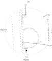
- the support protrusion 13 is also provided with a guide groove 132 communicating with the rotating hole 131, one end of the guide groove 132 away from the rotating hole 131 has an opening, and the guide groove 132 is used to guide the rotating shaft 241 to slide into the rotating hole 131.
- the rotating shaft 241 when installing the storage box 20, the rotating shaft 241 can be slid into the guide groove 132 through the opening of the guide groove 132, and can be slid into the rotating hole 131 through the guide groove 132. In this way, the rotating shaft 241 can be easily assembled into the rotating hole 131.
- the guide groove 132 is flared, the rotating shaft 241 can be easily slid into the guide groove 132 during assembly, so that the rotating shaft 241 can be inserted into the rotating hole 131.
- the guide groove 132 is disposed on the side of the rotating hole 131 away from the housing wall where the hidden opening 11 is located; thus, it is additionally convenient to assemble the rotating shaft 241.
- the guide groove 132 penetrates through the support protrusion 13.
- the guide groove 132 is smoothly connected with the rotating hole 131.
- a connection between the guide groove 132 on at least one of the support protrusions 13 and the rotating hole 131 is provided with a locking protrusion (not shown).
- the locking protrusion is used to limit the rotating shaft 241 to prevent it from escaping from the rotating hole 131.
- only one of the support protrusions 13 is provided with the locking protrusion.
- a thickening portion 133 is protruded on the periphery of the rotating hole 131 on the support protrusion 13.
- the structural strength of the rotating hole 131 can be improved, and the wear resistance of the rotating hole 131 can be increased.
- the contact area between the rotating shaft and the rotating hole 131 can also be increased, thereby increasing the rotational stability of the storage box.
- the thickening portion 133 is provided on the side of the support protrusion 13 facing away from the storage box 20.
- a protrusion 134 is provided on the side of the support protrusion 13 facing the storage box 20 (i.e., the inner side of the support protrusion 13).
- the protrusion 134 is used to abut the outer wall surface of the second side wall 24 during the rotation of the storage box 20.
- the protrusion 134 is disposed proximally to the rotating hole 131 and the guide groove 132, so that the structural strength of the support protrusion 13 at the rotation hole 131 and the guide groove 132 can be improved.
- the protrusion 134 extends in a direction away from the hidden opening 11, so as to improve the structural strength of the support protrusion 13 at the rotating hole 131 and the guide groove 132.
- the protrusion 134 can abut the outer wall surface of the second side wall 24. In this way, direct contact between the inner side surface of the support protrusion 13 and the outer wall surface of the second side wall 24 can be avoided. Therefore, the contact area between the support protrusion 13 and the outer wall surface of the second side wall 24 during rotation can be reduced, so as to reduce the rotation resistance of the storage box 20.
- the protrusion 134 is high in the middle and low at both ends, so as to further reduce the rotational resistance of the storage box 20.
- protrusions 134 there are two protrusions 134, and the two protrusions 134 are respectively provided on opposite sides of the rotating hole 131.
- one of the protrusions 134 is provided on the upper side of the rotating hole 131, and the other protrusion 134 is provided on the lower side of the rotating hole 131.
- the inner wall surface of the housing 10 is further provided protrudingly with a connecting protrusion 14, and the connecting protrusion 14 is disposed on one side of the hidden opening 11 to connect the two support protrusions 13.
- the structural strength and stability of the support protrusions 13 can be enhanced, so that the rotational stability of the storage box 20 can be enhanced.
- the two support protrusions 13 and the connecting protrusions 14 are enclosed on the outside of the storage box 20, and can also protect the storage box 20, to reduce the risk of damage caused by the collision between the storage box 20 and other components in the housing 10.
- the connecting protrusion 14 is integrally formed with the reinforcing ring protrusion 12.
- the connecting protrusion 14 is in the shape of a plate or a sheet.
- the rotating shaft 241 is disposed close to the first side wall 23. In this way, on the one hand, the protruding length of the support protrusion 13 can be reduced, and the rotation stability of the storage box 20 can be improved. In this embodiment, as shown in FIG. 7, FIG. 8 , FIG. 12 and FIG. 13 , the rotating shaft 241 is provided on the side of the second side wall 24 close to the first side wall 23.
- the storage box 20 also has a box bottom end opposite to its open end, and the rotating shaft 241 is disposed at the box bottom end. In this way, the rotation range of the storage box 20 can be reduced, so as to save the inner space of the housing 10.
- the rotating shaft 241 is disposed adjacent to the connection between the first side wall 23 and the second side wall 24.
- the hidden opening 11 has a first side edge (not shown) corresponding to the open end of the storage box 20, a second side edge (not shown) opposite to the first side edge, and two third side edges (not shown) adjacent to the first side edge.
- the hidden opening 11 is a square hole or is substantially a square hole.
- the open end of the storage box 20 when the storage box 20 is rotated from the second position to the first position, the open end of the storage box 20 will move in a direction close to the first side edge of the hidden opening 11. In this way, interference between the open end of the storage box 20 and the first side edge of the hidden opening 11 is avoided.
- the open end of the storage box 20 when in the second position, the open end of the storage box 20 is spaced from the first side edge of the hidden opening 11 to avoid interference with the edge (i.e., the first side edge) of the hidden opening 11 when the storage box 20 is rotated.
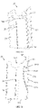
- the opening end of the second side wall 24 is formed with an avoidance notch 242 at the connection with the first side wall 23.
- the avoidance notch 242 avoids the edge of the hidden opening 11 (i.e., the first side edge) when the storage box 20 is rotated, so as to avoid interference with the edge of the hidden opening 11 (i.e., the first side edge) when the storage box 20 is rotated.
- the open end of the storage box 20 is inclined to avoid the edge (i.e., the first side edge) of the hidden opening 11 when the storage box 20 is rotated, to avoid interference with the edge (i.e., the first side edge) of the hidden opening 11 when the storage box 20 is rotated.
- Other escape structures may also be provided on the storage box 20 and/or the housing 10 to avoid interference with the edge (i.e., the first side edge) of the hidden opening 11 when the storage box 20 is rotated.
- the open end of the second side wall 24 is formed with an avoidance notch 242 at the connection with the first side wall 23, and the avoidance notch 242 extends for a predetermined length in the extending direction of the first side wall 23.
- the avoidance notch 242 is a stepped notch.
- the open end of the first side wall 23 protrudes from the open end of the second side wall 24 to form the avoidance notch 242.
- the open end of the first side wall 23 also protrudes from the open end of the third side wall (i.e., the side wall of the storage box 20 opposite to the first side wall 23).
- a gripping notch 243 is formed on the open end of the side wall of the storage box 20, and the gripping notch 243 is recessed toward the bottom of the storage cavity 21. In this way, by providing the gripping notch 243, when the remote control is stored in the storage cavity 21, the gripping notch 243 can expose the upper end of the remote control, so that it is convenient for the user to store or take the remote control.
- the gripping notch 243 is provided on the second side wall 24, so that it is convenient for the user to hold the remote control.
- each second side wall 24 is provided with a gripping notch 243, and the two gripping notch 243 are opposite to each other, so that it is additionally convenient for the user to hold the remote control.
- the gripping notch 243 is provided at the middle of the second side wall 24.
- a guide structure is provided on the storage box 20 and the housing 10, and the guide structure is used to guide the rotation of the storage box 20.
- the guide structure can be used to guide the storage box 20 to rotate from the first position to the second position; alternatively, the guide structure can be used to guide the storage box 20 to rotate from the second position to the first position. In this way, the rotational stability of the storage box 20 can be improved.
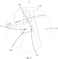
- an inner wall surface of the housing 10 is provided protrudingly with a guide support portion 15, a guide protrusion 151 is provided on one side of the hidden opening 11.
- the guide structure includes a guide protrusion 151 laterally protruding from the guide support portion 15, and a guide groove 144 provided on the outer wall surface of the storage box 20, and the guide protrusion 151 is slidably provided in the guide groove 244, and is configured to guide the rotation of the storage box 20.
- the guide protrusion 151 is provided on the side of the guide support portion 15 facing the hidden opening 11, and the guide groove 244 is provided on the outer wall surface of the second side wall 24. In this way, the storage box 20 can be guided to rotate with a simple structure.
- the guide groove 244 is an arc groove.
- the distal end of the guide protrusion 151 is provided with a spherical portion to reduce frictional force and rotational resistance.
- the spherical portion may be spherical, spheroid, ellipsoid, or the like.
- the guide groove 244 has an outer end close to the first side wall 23 and an inner end away from the first side wall 23, and the groove depth of the guide groove 244 increases from the outside to the inside. In this way, it is convenient to turn the storage box 20 from the second position to the first position, and it is also beneficial to limit the storage box 20 and the housing 10 when the storage box 20 is in the second position.
- the groove bottom of the guide groove 244 is an inclined surface or an arc surface.
- the guide support portion 15 is in the shape of a plate or a sheet.
- the guide support portion 15 is integrally formed with the reinforcing ring protrusion 12 to simplify the structure.
- each guide support portion 15 is provided with at least one guide protrusion 151.
- the two guide support portions 15 are disposed opposite to each other.
- the guide groove 244 is disposed adjacent to the open end of the storage box 20.
- the gripping notch 243 breaks the guide groove 244 to form two guide sub-grooves (not shown), and a fracture (not shown) is formed between the two guide sub-grooves.
- the guide protrusions 151 can be rotated within the fracture, thereby reducing the rotation resistance of the storage box 20.
- the guide protrusion 151 can be shared by the guide structure and the first limiting structure to simplify the structure.
- the first limiting structure further includes a guide protrusion 151 and a limiting groove 2441 provided at the bottom of the guide groove 244.
- the guide protrusion 151 is limited to the limiting groove 2441.
- the storage box 20 can be positioned/fixed at the second position. It can be understood that when the storage box 20 needs to be rotated, the user can force (i.e., pull) the storage box 20 to make the guide protrusion 151 escape from the limiting groove 2441.
- the first blocking protrusion 231 on the storage box 20 abuts the second blocking protrusion 121 on the housing 10 to prevent the storage box 20 from moving excessively.
- the guide protrusion 151 slides into the limiting groove 2441 to further limit the storage box 20 and the housing 10 to position/fix the storage box 20 in the second position.
- the guide structure can also be provided in other forms or other positions.
- the guide structure includes a guide arc protrusion on the second side wall 24 and a guide notch on the second side edge of the hidden opening 11.
- the guide arc protrusion is arc-shaped, and the guide arc protrusion is slidably disposed in the guide notch to guide the rotation of the storage box 20.
- the height of the guide arc protrusion increases from the inside to the outside, which is not repeated herein.
- the second blocking protrusion 121 is disposed corresponding to the third side edge of the hidden opening 11.
- the second blocking protrusion 121 is spaced apart from the second side edge of the hidden opening 11.
- An avoidance space is formed between the second blocking protrusion 121 and the second side edge of the hidden opening 11. In this way, on the one hand, the avoidance space can avoid the first blocking protrusion 231 when the storage box 20 is rotated.
- the first blocking protrusions 231 on the storage box 20 can pass through the avoidance space and be assembled to the outside of the housing 10.
- the two second blocking protrusions 121 are respectively disposed corresponding to the two third side edges of the hidden opening 11.
- the second limiting structure includes a stop protrusion 26 provided on the storage box 20, and the stop protrusion 26 is provided in the housing 10.
- the stop protrusion 26 In the first position, the stop protrusion 26 is in contact with the inner wall surface of the housing 10 to limit the storage box 20 and prevent it from moving too much.
- the stop protrusion 26 is in contact with the inner wall surface of the housing 10.
- the housing 10 is matched with the stop protrusion 26 to form the second stop structure, the structure can be simplified.
- a matching structure may also be provided on the inner wall surface of the housing 10 to abut the stop protrusion 26 at the first position.
- the stop protrusion 26 is disposed away from the rotation axis of the storage box 20 to increase the distance between the stop protrusion 26 and the rotation axis of the storage box 20, to increase the moment arm, thus the risk of damage to the stop protrusion 26 and the rotating shaft 241 is reduced.
- the stop protrusion 26 is provided on the second side wall 24 of the storage box 20.
- the stop protrusion 26 is disposed close to the open end of the storage box 20, and the stop protrusion 26 is disposed away from the first side wall 23.
- the stop protrusion 26 is rotatably provided on the storage box 20. In this way, when the storage box 20 is rotated to the first position, the stop protrusion 26 can be rotated in the process of interacting with the inner wall surface of the housing 10 so as to be rotated to a suitable position to abut the inner wall surface of the housing 10, thereby reducing the design accuracy and difficulty (that is, when designing, it is not necessary to consider the relationship between the inclination angle of the contact surface of the stop protrusion 26 and the maximum rotation angle of the storage box 20).
- the stop protrusion 26 may be in the shape of a plate, a sheet, or a block.
- the stop protrusion 26 is in the shape of a bent plate, which includes a rotating portion and a stop portion.
- the rotating portion is rotatably connected to the storage box 20, and the stop portion is used for abutting the inner wall surface of the housing 10.
- the stop protrusion 26 can also be set in a cylindrical shape or a quasi-cylindrical shape. At this time, the stop protrusion 26 can be integrally formed with the storage box 20 (it is not necessary to be rotatably connected).
- FIG. 1, FIG. 2 and FIG. 7 to FIG. 11 there are two stop protrusions 26.
- the two stop protrusions 26 are respectively disposed on the outer wall surface of the second side wall 24 of the storage box 20. In this way, the force applied to the storage box 20 in the first position can be more symmetrically balanced, thereby reducing the risk of damage to the stop protrusion 26.
- the first side wall 23 is provided with a gripping structure, and the gripping structure is used for the user to grasp.
- the user can drive the storage box 20 to rotate through the gripping structure, so as to facilitate the user to apply force, thereby improving the user's comfort.
- the gripping structure includes a buckle handle 232 formed by the indentation of the first side wall 23.
- the buckle handle 232 has a buckle opening 2321.
- the buckle handle 232 includes a first buckle wall 2322 and a second buckle wall 2323 disposed on opposite sides of the buckle opening 2321.
- the first buckle wall 2322 extends obliquely in a direction away from the second buckle wall 2323 from the outside to the inside.
- the second buckle wall 2323 extends obliquely toward the first buckle wall 2322 from the outside to the inside.
- the direction towards the bottom of the buckle handle 232 is inward, and the direction away from the bottom of the buckle handle 232 is outward.
- the first buckle wall 2322 extends obliquely from the outside to the inside in a direction away from the second buckle wall 2323, so that the user interacts with the first buckle wall 2322 to drive the storage box 20 to move.
- the first buckle wall 2322 is disposed on the side of the buckle opening 2321 toward the open end of the storage box 20.
- the second buckle wall 2323 extends obliquely toward the first buckle wall 2322 from the outside to the inside, so as to guide the user to interact with the first buckle wall 2322.
- the buckle handle 232 further includes a buckle bottom 2324, and the buckle bottom 2324 is disposed opposite to the buckle opening 2321.
- the gripping structure can also be provided in other structural forms, such as a lifting handle, etc., as long as it can be grasped by the user.
- guide ribs 25 are protruded on the inner wall surface of the storage cavity 21.
- the guide ribs 25 extend along the depth direction of the storage cavity 21.
- the height of the guide ribs 25 increases in the direction from the storage opening 22 to the bottom of the storage cavity 21.
- the height of the guide rib 25 increases in the insertion direction of the remote controller.
- the guide rib 25 can be used to guide the remote control to be inserted into the storage cavity 21, so that the remote control can be stored in the storage cavity 21.
- the guide ribs 25 can also be used to limit the remote controller to prevent the remote controller from shaking, so as to avoid noise caused by the shaking of the remote controller during the process of moving the mobile air conditioner 100.
- the width of the guide rib 25 increases in the direction from the storage opening 22 to the bottom of the storage cavity 21.
- the contact area between the guide rib 25 and the remote control can be increased to enhance the limiting effect, and on the other hand, the structural strength of the storage box 20 can also be increased.
- the two guide ribs 25 are respectively disposed on the inner wall surfaces of the two second side walls 24.
- the remote controller when the remote controller is stored in the storage box 20, the mobile air conditioner 100 is transported, the remote controller may be separated from the storage cavity 21 from the storage opening 22 and fall into the housing 10.
- the outer wall surface of the storage box 20 is provided with a thinning groove 245 corresponding to the guide rib 25, so that the thickness of the box wall of the storage box 20 can be uniform or relatively uniform.
- the mobile air conditioner 100 further includes a limiting member, and the limiting member is cooperatively connected with the storage box 20 for preventing the remote controller from being separated from the storage cavity 21.
- the limiting member is a box cover or protective foam (which can be sandwiched between the remote control and the inner wall surface of the storage cavity 21) or the like.
- the housing 10 includes a first housing wall (i.e., the upper housing wall in the state of FIG. 3 ) that is opposite to the storage opening 22 in the first position.
- the hidden opening 11 is disposed close to the first housing wall to prevent the remote controller from being separated from the storage cavity 21.
- the distance between the storage opening 22 and the first housing wall is smaller than the length of the remote control.
- the inner wall surface of the housing 10 is provided with a shift protrusion, and the shift protrusion is disposed corresponding to the storage opening 22 for preventing the remote control from being separated from the storage cavity 21.
- the use process of the storage box 20 is roughly as follows: 1) when the storage box 20 is rotated to the second position, the first blocking protrusion 231 on the storage box 20 is in contact with the second blocking protrusion 121 on the housing 10, and the guide protrusion 151 is limited to the limiting groove 2441; 2) when the storage opening 22 needs to be exposed, the user drives the storage box 20 to rotate through the buckle handle 232, and the guide protrusion 151 disengages from the guide groove 244 and slides along the guide groove 244, until the stop protrusion 26 abuts the inner wall surface of the housing 10, the storage box 20 is rotated to the second position and the storage opening 22 is exposed.
- the storage box 20 further includes a bottom wall 27 disposed opposite to the storage opening 22, and a through hole 271 is formed on the bottom wall 27.
- the through hole 271 is disposed close to the first side wall 23. In this way, it is easy to open the mold.
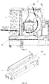
- the present disclosure further provides a method for assembling a storage box 20, including following operations.
- an open end of the storage box 20 is inserted into a hidden opening 11 from an inner side of a housing 10.
- the storage box 20 is inclined in the housing 10, and the open end of the storage box 20 (i.e., the upper end in FIG. 15 ) faces the hidden opening 11.
- the storage box 20 is subsequently moved to the direction close to the hidden opening 11, so that the open end of the storage box 20 is inserted into the hidden opening 11 from the inner side of the housing 10, and moved to the outside of the housing 10.
- the first blocking protrusion 231 of the storage box 20 can pass through the avoidance space.
- the method further includes operation S300, which includes controlling the rotation of the storage box 20 and rotating the open end of the storage box 20 into the hidden opening 11, so that the first blocking protrusion 231 on the storage box 20 is in contact with the second blocking protrusion 121 on the housing 10.
- the guide protrusion 151 slides into the limiting groove 2441 to rotate the storage box 20 to the first position, so that the storage box 20 is hidden from the housing 10.
- the storage box 20 is slidably disposed on the housing 10, so that the storage box 20 has a first position and a second position.
- the hidden opening 11 is close to the housing wall adjacent to the housing wall where the hidden opening 11 is located, and the storage box 20 is slidably disposed on the housing wall adjacent to the housing wall where the hidden opening 11 is located.
- the hidden opening 11 is provided on the left or right housing wall of the housing 10.
- the hidden opening 11 is provided close to the front housing wall or the rear housing wall of the housing 10, and the storage box 20 is slidably disposed on the inner wall surface of the front housing wall or the rear housing wall.
- the storage box 20 is slidably connected to the inner wall surface of the housing 10 through the guide rail structure.
- the storage box 20 is slidably connected to the inner wall surface of the housing 10 through a double guide rail structure.
- the mobile air conditioner 100 includes a housing 10 and a cross-flow fan (not shown).
- the housing 10 is provided with an indoor air inlet 11c, and the top of the housing 10 is provided with an indoor air outlet 12c.
- An indoor air duct communicating the indoor air inlet 11c with the indoor air outlet 12c is formed inside the housing 10.
- the cross-flow fan is installed in the indoor air duct.
- the indoor air outlet 12c is provided on the top of the housing 10. When the cross-flow fan is running, the indoor air enters the indoor air duct from the indoor air inlet 11c, and then blows out from the indoor air outlet 12c at the top.
- the rotation speed of the cross-flow fan can be directly increased to increase the air output from the indoor air outlet 12c. Since the indoor air outlet 12c is provided on the top of the housing 10, when the air is blown out, it will not directly act on the user. On the premise of ensuring that there is sufficient air volume for cooling and heating indoor air, and the cold air or hot air blown from the indoor air outlet 12c is prevented from directly blowing on the user, so as to prevent the user from feeling uncomfortable, such as excessive cold and overheating, and optimize the user experience.
- an indoor heat exchanger 4 needs to be provided on the air inlet of the volute assembly 3.
- the indoor air enters the interior of the housing 10 from the indoor air inlet 11c, and enters the indoor air duct after heat exchange with the indoor heat exchanger 4.
- the indoor air inlet 11c is optionally provided at the front or the rear of the housing 10.
- the user can move the position of the mobile air conditioner 100 according to actual needs. Take the direction the user is facing as the front, when the indoor air inlet 11c is provided at the front of the housing 10, the cross-flow fan directly extracts the air on the side of the user for heat exchange. A weak airflow is formed in the room so that the ambient temperature in the area where the user is located quickly reaches the target value.
- the indoor air inlet 11c is provided at the rear of the housing 10, the air on the user's side will not form airflow, and follow the ambient temperature to change evenly and slowly, improving comfort.
- the indoor air outlet 12c is provided with a guide grille 2c, and the guide grille includes 2c a plurality of longitudinal grille strips 21c extending along a length direction of the indoor air inlet 11c.
- the longitudinal grille strips 21c are inclined forwardly, that is, the direction of air outlet is consistent with the inclination direction of the longitudinal grille strips 21c. Since the longitudinal grille strips 21c are inclined forward, the hot air or cold air formed after the heat exchanger treatment directly acts on the upper part of the side where the user is located. The hot air or cold air will quickly exchange heat with the indoor ambient air during the blowing process, so that the ambient temperature on the user's side can quickly reach the target value. While the ambient temperature on the user's side is prioritized, the cold air or hot air blown from the indoor air outlet 12c is prevented from blowing directly on the user.
- the guide grille 2c further includes a plurality of horizontal grille strips 22c extending along a width direction of the indoor air outlet 12c.
- the horizontal grille strips 22c and the longitudinal grille strips 21c are alternately arranged, and the longitudinal grille strips 21c protrude upward from the horizontal grille strips 22c. That is, the guide grille 2c includes an inner grille layer and an outer grille layer.
- the inner grille layer is formed by crisscrossing longitudinal grille strips 21c and horizontal grille strips 22c
- the outer grille is formed by the parts of the longitudinal grille strips 21c protruding outward from the horizontal grille strips 22c.
- the crisscrossed inner grille can make the air outlet more uniform and has a dust-proof effect, and the outer grille is more aesthetically appealing, and has the effect of guiding the air and reducing the loss of air volume.
- the mobile air conditioner 100 further includes a volute assembly 3, and the volute assembly 3 includes a volute 31 and a volute cover 32, and the volute 31 and the volute cover 32 cooperate to form an indoor air duct. That is, the volute assembly 3 is formed by splicing the volute 31 and the volute cover 32.
- the cross-flow fan it is possible to first fix the cross-flow fan with the volute 31 or the volute cover 32, and then combine the volute 31 and the volute cover 32.
- the cross-flow fan is provided in the indoor air duct formed by splicing the volute 31 and the volute cover 32.
- the mobile air conditioner 100 further includes an indoor heat exchanger 4 provided on the air inlet of the volute assembly 3.
- the volute cover 32 includes a top plate 321 disposed above the indoor heat exchanger 4, and the top plate 321 is recessed downward on the air outlet of the indoor heat exchanger 4 to form a water diversion groove 322.
- the air treated by the indoor heat exchanger 4 is blown out from the top, which makes it easy to exchange heat with the ambient air to form condensed water.
- the water diversion groove 322 is provided to collect the condensed water.
- the top plate 321 shields the indoor heat exchanger 4 to prevent the condensed water from dripping on the indoor heat exchanger 4, thereby preventing the condensed water from entering the indoor air duct.
- the water diversion groove 322 is surrounded by the first side wall 322a, the bottom plate 322b and the second side wall 322c.
- the air outlet of the volute assembly 3 is formed between the first side wall 322a and the air duct plate of the volute 31, and the air outlet is connected to the indoor air outlet 12c.
- the hot air or cold air is prevented from overflowing from the gap between the air outlet and the indoor air outlet 12c, which affects the air outlet effect of the entire mobile air conditioner 100.
- the top plate 321 is provided with a water-stop flange 323 with an opening on one side, and the opening of the water-stop flange 323 faces the water diversion groove 322.
- the condensed water formed at the indoor air outlet 12c will adhere to the top plate 321 and accumulate and flow on the top plate 321.
- the water-stop flange 323 provided on the top plate 321 can restrict the flow direction of the condensed water.
- the condensed water flows down the second side wall 322c of the water diversion groove 322 and enters the water diversion groove 322 to prevent the condensed water from flowing down from the side of the top plate 321 to the indoor heat exchange air duct.
- the water-stop flange 323 can be provided on the edge of the top plate 321, and the shape of the water-stop flange 323 and the connection position between the water-stop flange 323 and the top plate 321 can also be designed according to specific needs.
- the volute cover 32 further includes a first side plate 324 and a second side plate 325 respectively disposed at both ends of the top plate 321.
- the bottom of the water diversion groove 322 is inclined downward from the second side plate 325 to the first side plate 324.
- the first side plate 324 is provided with a water diversion notch 326 communicating with the water diversion groove 322.
- the first side plate 324 and the second side plate 325 can support the cross-flow fan.
- the bottom of the water diversion groove 322 is inclined downward from the direction of the second side plate 325 to the first side plate 324 for guiding the condensed water to flow in the inclined direction until it is discharged from the water diversion notch 326.
- the lower end of the first side plate 324 is provided with a fan installation hole 327 for installing the cross-flow fan.
- the outer side of the first side plate 324 is further provided with a drainage structure 328, and the drainage structure 328 is used to guide the water flowing out of the water diversion notch 326 away from the fan installation hole 327.
- the cross-flow fan is rotatably connected to the first side plate 324 through the installation hole, and the cross-flow fan rotates relative to the first side plate 324 to form an air flow.
- the drainage structure 328 can prevent the condensed water from entering the indoor air duct from the fan installation hole 327.
- the drainage structure 328 may be two water-stop ribs disposed on the first side plate 324 and located on the upper side of the fan installation hole 327, the two water-stop ribs are arranged oppositely, and the high ends of the two water-stop ribs are connected. In this way, the condensed water flows down along the water-stop rib, and it is ensured that the condensed water flowing out from the water diversion notch 326 will not flow to the fan installation hole 327 and the axial flow fan.
- the drainage structure 328 may also be a water-stop rib disposed on the first side plate 324 and connected to the first side wall 322a.
- the upper edge of the water-stop rib is flush with the upper edge of the first side wall 322a, and the lower edge of the water-stop rib is located on the side of the fan installation hole 327 close to the indoor heat exchanger 4.
- the mobile air conditioner 100 further includes a middle baffle 5 provided in the housing 10 and an indoor heat exchanger 4.
- the volute assembly 3 and the indoor heat exchanger 4 are both provided on the middle baffle 5.
- the indoor heat exchanger 4 is provided on the middle baffle 5 of the volute assembly 3 at the air inlet, and is provided with a water storage groove 6 and a drainage groove 7 communicating with the water storage groove 6.
- the drainage groove 7 is provided below the volute assembly 3, and is arranged corresponding to the outdoor heat exchanger of the mobile air conditioner 100.
- the bottom of the water storage groove 6 is inclined in the direction of the drainage groove 7, and the indoor heat exchanger 4 is installed in the water storage groove 6.
- the condensed water can flow into the drainage groove 7 through the water storage groove 6, and then the condensed water can flow into the outdoor heat exchanger through the drainage groove 7.
- the flow rate of the condensed water in the water storage groove 6 can be increased, so as to improve the discharge rate of the condensed water. Therefore, the discharge effect of the condensed water in the mobile air conditioner 100 is improved, and the condensed water can be effectively prevented from accumulating in the water storage groove 6.
- the indoor heat exchanger 4 may be inclined in a direction close to the volute assembly 3.
- the inclined arrangement of the indoor heat exchanger 4 is convenient to cooperate with the bottom of the water storage groove 6, and the heat exchange area can be increased.
- the embodiment of the present disclosure also provides a housing 10. It can be understood that the housing 10 can be applied to a mobile air conditioner. The specific structure of the housing 10 will be mainly described below.
- the housing 10 includes a housing body 1 and a reinforcing housing 2.
- the reinforcing housing 2 is provided in the housing body 1 and is fixedly connected with the inner surface of the housing body 1.
- the housing body 1 is roughly in the shape of a quadrangular prism with a quadrangular bottom surface.
- the housing body 1 can be made of metal, such as stainless steel, aluminum, aluminum alloy, copper, copper alloy, iron, iron alloy, or the like.
- the housing body 1 can also be made of rigid plastics, such as ABS (acrylonitrile-butadiene-styrene terpolymer), POM (polyoxymethylene), PS (polystyrene), PMMA (polymethyl methacrylate), PC (polycarbonate), PET (polyethylene terephthalate), PBT (polybutylene terephthalate), PPO (polyphenylene ether), or the like.
- the housing body 1 can also be made of other alloy materials, or a mixture of metal materials and plastics, as long as the stability of the housing body 1 can be better improved. In this way, it is more beneficial to improve the installation stability of the housing body 1, thereby effectively improving the practicability, reliability, and durability of the housing body 1.
- the housing body 1 in order to make the appearance of the housing10 aesthetically appealing and make the overall weight of the housing 10 light, the housing body 1 can be optionally made of plastic material. It can be understood that, in order to further improve the overall structural strength of the housing 10, by arranging a reinforcing housing 2 in the housing body 1, the overall strength of the housing 10 can be improved by using the reinforcing housing 2.
- the reinforcing housing 2 is a sheet metal housing or a rigid plastic housing. In this embodiment, the reinforcing housing 2 can be made of sheet metal material or metal casting.
- the housing 10 is provided with the reinforcing housing 2.
- the reinforcing housing 2 is provided in the housing body 1 and is fixedly connected with the inner surface of the housing body 1, so that the reinforcing housing 2 strengthens the housing body 1 to improve the overall strength of the housing 10.
- the housing 10 is applied to the mobile air conditioner, thereby improving the structural strength and installation stability of the mobile air conditioner.
- the housing body 1 includes a front housing 11a and a rear housing 12a which are detachably connected. It can be understood that the front housing 11a and the rear housing 12a enclose an installation space, and the reinforcing housing 2 is installed in the installation space. In order to make the reinforcing housing 2 improve the overall strength of the housing 10, the reinforcing housing 2 abuts or connects with the inner wall of the housing body 1, that is, the shape outline of the reinforcing housing 2 is equivalent to the shape outline of the installation space enclosed by the front housing 11a and the rear housing 12a.
- the front housing 11a and the rear housing 12a are connected in a detachable manner, such as snap connection, plug fit, screw connection or pin connection, or the like, as long as the structure can implement the detachable connection between the front housing 11a and the rear housing 12a, which is not limited herein.
- one of the front housing 11a and the rear housing 12a is provided with a clamping protrusion 113
- another of the front housing 11a and the rear housing 12a is provided with a clamping slot 121a
- the front housing 11a is detachably connected to the rear housing 12a through the cooperation of the clamping protrusion 113 and the clamping slot 121a.
- the front housing 11a is provided with the clamping protrusion 113
- the rear housing 12a is provided with the clamping slot 121a
- the front housing 11a is detachably connected to the rear housing 12a through the cooperation of the clamping protrusion 113 and the clamping slot 121a.
- the front housing 11a can also be provided with the clamping slot 121a
- the rear housing 12a is provided with the clamping protrusion 113.
- the housing 10 is a housing of the mobile air conditioner, the front housing 11a is located at the front of the mobile air conditioner, and the rear housing 12a is located at the rear of the mobile air conditioner.
- the front housing 11a includes a front panel and front side plates on both sides of the front panel, the two front side plates are formed by bending two sides of the front panel, that is, the front panel and the two front side plates are integrally formed.
- the front housing 11a is U-shaped.
- the rear housing 12a includes a rear panel and rear side panels on both sides of the rear panel. The two rear side panels are formed by bending two sides of the rear panel, that is, the rear panel and the two rear side panels are integrally formed.
- the rear housing 12a is U-shaped.
- the sides of the two front side plates of the front housing 11a away from the front panel are provided with a plurality of spaced-apart clamping protrusions 113 and the sides of the two rear side panels of the rear housing 12a away from the rear panel are provided with a plurality of spaced-apart clamping slots 121a.
- each clamping protrusion 113 is snap-fitted or plug-fitted with each clamping slot 121a.
- the reinforcing housing 2 can also be integrally formed on the inner wall of the housing body 1. That is, the reinforcing housing 2 also includes two parts, and the front housing 11a and the rear housing 12a of the housing body 1 both correspond to a part of the reinforcing housing 2.
- the front housing 11a, the rear housing 12a and the reinforcing housing 2 can be made by using interference fit, heat fusion and integral molding processes.
- the reinforcing housing 2 is detachably connected to the front housing 11a and/or the rear housing 12a, that is, the front housing 11a and/or the rear housing 12a and the reinforcing housing 2 are connected by a split structure, for example, a snap connection, a plug fit, a screw connection or a pin connection, or the like, as long as the structure can implement the detachable connection between the front housing 11a and/or the rear housing 12a and the reinforcing housing 2, which is not limited herein.
- a split structure for example, a snap connection, a plug fit, a screw connection or a pin connection, or the like
- the side edges of the front housing 11a or the rear housing 12a are provided protrudingly with a plurality of spaced-apart lugs 111.
- Each lug 111 defines a first via hole 112.
- the reinforcing housing 2 is provided with a first connection hole 29 corresponding to each of the first via holes 112.
- the reinforcing housing 2 is connected to the front housing 11a or the rear housing 12a through the first through hole 112 and the first connection hole 29 in sequence through fasteners.
- a lug 111 is protruded from the side of the front housing 11a or the rear housing 12a, and the lug 111 defined the first through hole 112. After the housing 10 is assembled, the front housing 11a or the rear housing 12a can be used to hide the lug 111, the first through hole 112 and the fastener, which effectively ensures the overall appearance of the housing body 1.
- the sides of the two front side plates of the front housing 11a away from the front panel are provided protrudingly with a plurality of spaced-apart lugs 111, each lug 111 defines a first via hole 112, and the reinforcing housing 2 defines a first connection hole 29 corresponding to each first via hole 112.
- the fasteners can be passed through the first through hole 112 and the first connection hole 29 in sequence, so that the lugs 111 of the front housing 11a can be connected to the reinforcing housing 2.
- the lugs 111 may also be disposed on the sides of the two rear side panels of the rear housing 12a away from the rear panel, which is not limited herein.
- the reinforcing housing 2 includes a front plate 21a, a rear plate 22a, a left plate 23a and a right plate 24a.
- the front plate 21a, the rear plate 22a, the left plate 23a and the right plate 24a are fixedly connected to the inner surface of the housing body 1.
- the front plate 21a of the reinforcing housing 2 is disposed opposite to the front plate of the front housing 11a
- the rear plate 22a is disposed opposite to the rear plate of the rear housing 12a.
- the left plate 23a and the right plate 24a are respectively disposed to face the two front side plates of the front housing 11a and the two rear side panels of the rear housing 12a.
- the two front side plates of the front housing 11a are connected to the left plate 23a and the right plate 24a of the reinforcing housing 2 through the lugs 111. That is, the left plate 23a and the right plate 24a respectively define the first connection holes 29 corresponding to the lugs 111 of the two front side plates of the front housing 11a.
- the front plate 21a, the rear plate 22a, the left plate 23a and the right plate 24a can also be integral structural parts, so that the integral structural parts fixed on the housing body 1 are simpler and easier to fix than the discrete structural parts.
- a first folded edge 231a is formed on the side of the left plate 23a adjacent to the front plate 21a and/or the rear plate 22a, and the first folded edge 231a is provided with a first through hole 232a.
- the front plate 21a and/or the rear plate 22a are provided with first fixing holes 27a corresponding to the first through hole 232a, the front plate 21a and/or the rear plate 22a are connected to the first folded edge 231a through the first fixing hole 27a and the first through hole 232a in sequence through fasteners.
- the two sides of the left plate 23a are bent to form a first folded edge 231a.
- the front plate 21a and the rear plate 22a are in contact with the first folded edges 231a on both sides of the left plate 23a, respectively, and pass through the first fixing hole 27a and the first through hole 232a in sequence through fasteners, thereby achieving the fixed connection of the left plate 23a to the front plate 21a and the rear plate 22a.
- the side edges of the front plate 21a and/or the rear plate 22a may also be bent to form the first folded edge 231a, which is not limited herein.
- a second folded edge 241a is formed on the side of the right plate 24a adjacent to the front plate 21a and/or the rear plate 22a, and the second folded edge 241a is provided with a second through hole 242a.
- the front plate 21a and/or the rear plate 22a are provided with second fixing holes 28 corresponding to the second through holes 242a, the front plate 21a and/or the rear plate 22a are connected to the second folded edge 241a through the second fixing hole 28 and the second through hole 242a in sequence through fasteners.
- the two sides of the right plate 24a are bent to form a second folded edge 241a.
- the front plate 21a and the rear plate 22a are in contact with the second folded edges 241a on both sides of the right plate 24a, respectively, and pass through the second fixing hole 28 and the second through hole 242a in sequence through fasteners, thereby achieving the fixed connection of the right plate 24a to the front plate 21a and the rear plate 22a.
- the side edges of the front plate 21a and/or the rear plate 22a may also be bent to form the second folded edge 241a, which is not limited herein.
- the housing 10 further includes a middle baffle 5, the reinforcing housing 2 is formed with an accommodating cavity 2a, and the middle baffle 5 is provided in the accommodating cavity 2a to separate the accommodating cavity 2a.
- the front plate 21a, the rear plate 22a, the left plate 23a and the right plate 24a of the reinforcing housing 2 are enclosed to form an accommodating cavity 2a, and the middle baffle 5 is provided in the accommodating cavity 2a.
- the periphery of the middle baffle 5 is connected with the front plate 21a, the rear plate 22a, the left plate 23a and the right plate 24a, such that the middle baffle 5 divides the accommodating cavity 2a into upper and lower installation spaces for installing other components of the mobile air conditioner.
- the reinforcing housing 2 is used to implement the stable installation of the middle baffle 5, thereby improving the installation stability of the middle baffle 5.
- a support member 25a is provided on the side of the reinforcing housing 2 facing the middle baffle 5, and the middle baffle 5 is in limited contact with the support member 25a.
- the surface of the reinforcing housing 2 facing the middle baffle 5 is provided with a support member 25a, that is, the support member 25a is a support plate, a support sheet or a support strip.
- the support member 25a can be arranged around the middle baffle 5, that is, the periphery of one surface of the middle baffle 5 is in limited contact with the support member 25a.
- the support members 25a may also be provided only on the surfaces of opposite sides of the reinforcing housing 2.
- the support member 25a is provided on the front plate 21a and the rear plate 22a of the reinforcing housing 2, or on the left plate 23a and the right plate 24a of the reinforcing housing 2, which are not limited herein.
- the side of the reinforcing housing 2 facing the middle baffle 5 is provided with a plurality of support members 25a arranged at intervals, and the middle baffle 5 is in limited contact with the plurality of support members 25a. It can be understood that this arrangement is beneficial to saving materials and reducing costs.
- the surfaces of the left plate 23a and the right plate 24a of the reinforcing housing 2 facing the side of the middle baffle 5 are provided with a plurality of support members 25a arranged at intervals.
- the plurality of support members 25a are arranged in a linear manner, so as to ensure the stability of the middle baffle 5 after installation.
- the support member 25a may also be formed by bending a part of the left plate 23a or the right plate 24a. That is, a gap is formed at the left plate 23a or the right plate 24a corresponding to the support member 25a, and one end of the support member 25a is integrally connected with the inner wall of the gap, so that the size of the gap is equivalent to that of the support member 25a.
- a plurality of second via holes 26a are defined in the reinforcing housing 2 adjacent to the support member 25a, and the middle baffle 5 is provided with a second connection hole 51 corresponding to each second via hole 26a.
- the middle baffle 5 is connected to the reinforcing housing 2 through the second through hole 26a and the second connection hole 51 in sequence through fasteners.
- the left plate 23a and the right plate 24a of the reinforcing housing 2 are provided with support members 25a.
- the left plate 23a and the right plate 24a of the reinforcing housing 2 have a plurality of second via holes 26a adjacent to the support member 25a.
- a second connection hole 51 is formed on the periphery of the middle baffle 5 corresponding to each second via hole 26a.
- the middle baffle 5 is connected to the left plate 23a and the right plate 24a of the reinforcing housing 2 through the second through hole 26a and the second connection hole 51 in sequence through fasteners, thereby further improving the installation stability of the middle baffle 5.
- the housing body 1 further includes a top plate 13a located on top of the front housing 11a and the rear housing 12a. It can be understood that the top plate 13a and the front housing 11a and the rear housing 12a are detachably connected, such as snap connection, plug fit, screw connection or pin connection, etc., which are not limited herein.
- the top plate 13a is further provided with an air outlet, which can be used for air intake or air outlet.
- the reinforcing housing 2 forms a hollow area for the air vent of the top plate 13a, that is, the reinforcing housing 2 is not provided.
- the top plate 13a may not be provided with air vents, but the air vents may be provided on the front housing 11a, so that the top plate 13a can be provided with a reinforcing housing 2, which can be selectively provided according to specific conditions.
- the housing body 1 further includes a chassis 14a located at the bottoms of the front housing 11a and the rear housing 12a. It can be understood that the chassis 14a is detachably connected with the front housing 11a and the rear housing 12a, such as snap connection, plug fit, screw connection or pin connection, which is not limited herein.
- the chassis 14a is provided with a limiting groove, and the bottom of the reinforcing housing 2 is limited in the limiting groove, so that the limit installation of the reinforcing housing 2 and the chassis 14a can be implemented, thereby improving the overall stability of the housing 10.
- the housing 10 is applied to a mobile air conditioner.
- the chassis 14a is provided with rollers.
- the embodiment of the present disclosure also provides a housing 10. It can be understood that the housing 10 can be applied to a mobile air conditioner. The specific structure of the housing 10 will be mainly described below.
- the housing 10 includes a front housing 11a and a top plate 13a, the front housing 11a is provided with a first positioning member and a first locking member, and the top plate 13a is provided with a second positioning member and a second locking member.
- the top plate 13a is connected to the front housing 11a through the cooperation of the first positioning member and the second positioning member, and is fixedly connected by the first locking member and the second locking member, so that the top plate 13a is fixedly connected to the front housing 11a.
- the housing 10 is substantially a quadrangular prism with a quadrangular bottom.
- the housing 10 can be made of metal, such as stainless steel, aluminum, aluminum alloy, copper, copper alloy, iron, iron alloy, or the like.
- the housing 10 can also be made of rigid plastics, such as ABS, POM, PS, PMMA, PC, PET, PBT, PPO, or the like.
- the housing 10 can also be made of other alloy materials, or a mixture of metal materials and plastics, as long as the stability of the housing 10 can be better improved. In this way, it is more beneficial to improve the installation stability of the housing 10, thereby effectively improving the practicability, reliability, and durability of the housing 10.
- the housing 10 in order to make the appearance of the housing 10 aesthetically appealing and the overall weight of the housing light, the housing 10 can be optionally made of plastic material.
- a reinforcing structure or a reinforcing housing can be provided in the housing 10, and the overall strength of the housing 10 can be improved by using the reinforcing structure or the reinforcing housing.
- the reinforcing structure or the reinforcing housing may be made of sheet metal material or metal casting, which is not limited herein.
- the housing 10 includes a front housing 11a, a rear housing 12a, and a top plate 13a on top of the front housing 11a and the rear housing 12a.
- a front housing 11a a rear housing 12a
- a top plate 13a on top of the front housing 11a and the rear housing 12a.
- the front housing 11a and the top plate 13a are pre-fixed by the positioning and cooperation of the first positioning member and the second positioning member, thereby effectively avoiding the problem of skewing and loosening of the housing 10 and uneven gaps during the installation process.
- the front housing 11a and the top plate 13a are fixedly installed by using the fixed connection of the first locking member and the second locking member, thereby improving the installation stability of the front housing 11a and the top plate 13a.
- the rear housing 12a is provided with a third positioning member and a third locking member
- the top plate 13a is provided with a fourth positioning member and a fourth locking member
- the top plate 13a is connected to the rear housing 12a through the positioning cooperation of the third positioning member and the fourth positioning member, and is fixedly connected by the third locking member and the fourth locking member, so that the top plate 13a is fixedly connected to the rear housing 12a.
- a third positioning member and a fourth positioning member are respectively provided on the rear housing 12a and the top plate 13a, such that the rear housing 12a and the top plate 13a are pre-fixed by the positioning cooperation of the third positioning member and the fourth positioning member, thereby effectively preventing the housing 10 from being skewed and loosened during the installation process and the problem of uneven gaps.
- a third locking member and a fourth locking member are respectively provided on the rear housing 12a and the top plate 13a, such that the rear housing 12a and the top plate 13a are fixedly installed by using the fixed connection of the first locking member and the second locking member, thereby improving the installation stability of the rear housing 12a and the top plate 13a.
- one of the first positioning member and the second positioning member is provided with a buckle 11a11, the other of the first positioning member and the second positioning member is provided with an insertion hole 13a1, and the top plate 13a is connected to the front housing 11a through the plug-in fitting of the buckle 11a11 and the insertion hole 13a1.
- one of the third positioning member and the fourth positioning member is provided with the buckle 11a11
- the other one of the third positioning member and the fourth positioning member is provided with an insertion hole 13a1
- the top plate 13a is connected to the rear housing 12a through the plug-fit of the buckle 11a11 and the insertion hole 13a1.
- one of the front housing 11a and the top plate 13a is provided with a buckle 11a11, and the other of the front housing 11a and the top plate 13a is provided with an insertion hole 13a1, the top plate 13a is connected to the front housing 11a through the plug-in fitting of the buckle 11a11 and the insertion hole 13a1, so as to implement the pre-fixation during the installation process of the top plate 13a and the front housing 11a.
- one of the rear housing 12a and the top plate 13a is provided with a buckle 11a11, and the other of the rear housing 12a and the top plate 13a is provided with an insertion hole 13a1, the top plate 13a is connected to the rear housing 12a through the plug-in fitting of the buckle 11a11 and the insertion hole 13a1, so as to implement the pre-fixation during the installation of the top plate 13a and the rear housing 12a.
- the front housing 11a is provided with a buckle 11a11, and the top plate 13a is provided with an insertion hole 13a1, and the top plate 13a is pre-fixed with the front housing 11a through the insertion of the buckle 11a11 and the insertion hole 13a1.
- the front housing 11a may also be provided with an insertion hole 13a1, and the top plate 13a is provided with a buckle 11a11, which is not limited herein.
- the rear housing 12a may also be provided with a buckle 11a11, the top plate 13a is provided with an insertion hole 13a1, and the top plate 13a is pre-fixed to the rear housing 12a through the cooperation of the buckle 11a11 and the insertion hole 13a1.
- the rear housing 12a may also be provided with the insertion hole 13a1, and the top plate 13a is provided with the buckle 11a11, which is not limited herein.
- both the front housing 11a and the rear housing 12a are provided with the buckles 11a11, the top plate 13a is provided with the insertion hole 13a1, the top plate 13a is pre-fixed with the front housing 11a and the rear housing 12a through the plug-in engagement of the buckle 11a11 and the insertion hole 13a1.
- the front housing 11a and the rear housing 12a may also be provided with insertion holes 13a1, and the top plate 13a may be provided with the buckles 11a11.
- the front housing 11a is provided with the buckle 11a11
- the rear housing 12a is provided with the insertion hole 13a1
- the side of the top plate 13a facing the front housing 11a is provided with an insertion hole 13a1
- the side of the top plate 13a facing the rear housing 12a is provided with a buckle 11a11, such that the two sides of the top plate 13a can be pre-fixed with the front housinglla and the rear housing 12a through the plug-in fitting of the buckle 11a11 and the insertion hole 13a1 respectively, which is not limited herein.
- the buckle 11a11 can be selected as a structure such as a plug board, a plug post, and a plug strip, and the insertion hole 13a1 can be selected as a structure such as a through hole or a groove.
- the housing 10 is a housing of the mobile air conditioner
- the front housing 11a is located at the front of the mobile air conditioner
- the rear housing 12a is located at the rear of the mobile air conditioner.
- the front housing 11a and the rear housing 12a enclose an installation space for installing other components of the mobile air conditioner.
- the front housing 11a includes a front panel 11a1 and front side plates 11a2 located on both sides of the front panel 11a1, the two front side plates 11a2 are formed by bending two sides of the front panel 11a1, that is, the front panel 11a1 and the two front side plates 11a2 are integrally formed.
- the front housing 11a has a U-shaped structure.
- the rear housing 12a includes a rear panel and rear side panels located on both sides of the rear panel, and the two rear side panels are formed by bending two sides of the rear panel, that is, the rear panel and the two rear side panels are integrally formed.
- the rear housing 11 has a U-shaped structure.
- the front housing 11a and the rear housing 12a are connected in a detachable manner, such as snap connection, plug fit, screw connection or pin connection, etc., as long as the structure can implement the detachable connection between the front housing 11a and the rear housing 12a, which is not limited herein.
- one of the front housing 11a and the rear housing 12a is provided with a clamping protrusion
- the other one of the front housing 11a and the rear housing 12a is provided with a clamping slot
- the front housing 11a is detachably connected to the rear housing 12a through the cooperation of the clamping protrusion and the clamping slot.
- the front housing 11a is provided with a clamping protrusion
- the rear housing 12a is provided with a clamping slot
- the front housing 11a is detachably connected to the rear housing 12a through the cooperation of the clamping protrusion and the clamping slot.
- the front housing 11a may also be provided with a clamping slot
- the rear housing 12a may be provided with a clamping protrusion. This arrangement can facilitate the disassembly and assembly of the housing 10.
- the sides of the two front side plates 11a2 of the front housing 11a away from the front panel 11a1 are provided with a plurality of spaced-apart clamping protrusions
- the sides of the two rear side panels of the rear housing 12a away from the rear panel are provided with a plurality of spaced-apart clamping slots.
- the front housing 11a protrudes with a plurality of spaced-apart buckles 11a11, the top plate 13a defines an insertion hole 13a1 corresponding to each buckle 11a11, and each buckle 11a11 is inserted into each insertion hole 13a1.
- the installation space enclosed by the front housing 11a and the rear housing 12a forms an installation opening at the top thereof that communicates with the installation space
- the top plate 13a is installed at the installation opening.
- the installation opening formed by the front housing 11a and the rear housing 12a is square or quadrilateral, and the shape and outline of the top plate 13a are equivalent to the shape and outline of the installation opening.
- the top plate 13a is formed with four side edges corresponding to the front panel 11a1 of the front housing 11a, the rear panel of the rear housing 12a, the two front side plates of the front housing 11a, and the two rear side panels of the rear housing 12a.
- the front panel 11a1 of the front housing 11a is provided protrudingly with a plurality of spaced-apart buckles 11a11, a side edge of the top plate 13a corresponding to the front panel 11a1 of the front housing 11a is provided with an insertion hole 13a1 corresponding to each buckle 11a11, and the front panel 11a1 and the top plate 13a of the front housing 11a are inserted into each insertion hole 13a1 through each buckle 11a11 to achieve pre-fixation.
- the rear panel of the rear housing 12a is provided protrudingly with a plurality of spaced-apart buckles 11a11, a side edge of the top plate 13a corresponding to the rear panel of the rear housing 12a is provided with an insertion hole 13a1 corresponding to each buckle 11a11, and the rear panel and the top plate 13a of the rear housing 12a are inserted into each insertion hole 13a1 through each buckle 11a11 to achieve pre-fixation.
- the end of the buckle 11a11 away from the front housing 11a is provided with a guide slope 11a12, and the buckle 11a11 fits with the guide slope 11a12 and slides into the insertion hole 13a1.
- a guide slope 11a12 is provided at the end of the buckle 11a11, when the buckle 11a11 is inserted into the insertion hole 13a1, the guide slope 11a12 of the buckle 11a11 fits with the hole wall of the insertion hole 13a1 and can be easily slid into the insertion hole 13a1, thereby improving the efficiency and convenience of plugging.
- the hole wall of the insertion hole 13a1 is provided with a guide surface 13a2, and the buckle 11a11 slides into the insertion hole 13a1 along the guide surface 13a2.
- the guide surface 13a2 is provided on the hole wall of the insertion hole 13a1, when the buckle 11a11 is inserted into the insertion hole 13a1, the end of the buckle 11a11 fits the guide surface 13a2 of the hole wall of the insertion hole 13a1 and can be easily slid into the insertion hole 13a1, thereby improving the efficiency and convenience of plugging.
- each buckle 11a11 is provided with a guide slope 11a12, and the hole wall of each insertion hole 13a1 is provided with a guide surface 13a2.
- the guide slope 11a12 of each buckle 11a11 fits with the guide surface 13a2 of the hole wall of each insertion hole 13a1 to facilitate sliding into the insertion hole 13a1.
- the buckle 11a11 includes two oppositely arranged first connecting plates 11a13 and a second connecting plate 11a14 connecting the two first connecting plates 11a13, the buckle 11a11 is inserted into the insertion hole 13a1, so that the side of the two first connecting plates 11a13 facing away from the second connecting plate 11a14 is in limited contact with the top plate 13a.
- the buckle 11a11 as a plug structure formed by the cooperation of two first connecting plates 11a13 and one second connecting plate 11a14 is beneficial to improve the structural stability of the buckle 11a11.
- the two first connecting plates 11a13 of the buckle 11a11 are in contact with the inner wall of the top plate 13a, thereby improving the pre-fixing stability of the top plate 13a and the front housing 11a and/or the rear housing 12a, thereby effectively avoiding problems such as skewing and loosening and uneven gaps occurring when the front housing 11a and/or the rear housing 12a and the top plate 13a are installed.
- the second connecting plate 11a14 and the two first connecting plates 11a13 are enclosed to form a groove structure, so that the cost of the structure of the buckle 11a11 can be saved.
- the insertion hole 13a1 is a rectangular elongated hole or a strip-shaped hole.
- the first locking member is a connecting portion 121b protruding from the front housing 11a, and the connecting portion 121b is provided with a through hole 122.
- the second locking member is provided with a connecting hole 13a3 located on the top plate 13a, and the top plate 13a is fixedly connected to the front housing 11a through the through hole 122 and the connecting hole 13a3 in sequence through fasteners.
- a connecting portion 121b is provided on the front side plate 11a2 of the front housing 11a, and a via hole 122 is defined at the connecting portion 121b, and a connecting hole 13a3 is defined on the side of the top plate 13a corresponding to the front side plate 11a2 corresponding to the via hole 122, such that the top plate 13a can be fixedly connected to the front side plate 11a2 of the front housing 11a through the through holes 122 and the connecting holes 13a3 through the fasteners in turn, thereby improving the installation stability of the top plate 13a and the front housing 11a.
- the third locking member is a connecting portion 121b protruding from the rear housing 12a
- the connecting portion 121b is provided with a through hole 122
- the fourth locking member is provided with a connecting hole 13a3 located on the top plate 13a
- the top plate 13a is fixedly connected to the rear housing 12a through the through hole 122 and the connecting hole 13a3 in sequence through fasteners.
- a connecting portion 121b is protruded on the rear side panel of the rear housing 12a, a via hole 122 is defined at the connecting portion 121b, and a connecting hole 13a3 is defined at the side of the top plate 13a corresponding to the rear side panel corresponding to the via hole 122, such that the top plate 13a can be fixedly connected to the rear side panel of the rear housing 12a through the through hole 122 and the connecting hole 13a3 through the fasteners in sequence, thereby improving the installation stability of the top plate 13a and the rear housing 12a.
- the two front side plates 11a2 of the front housing 11a are both protrudingly provided with connecting portions 121b, and the top plate 13a corresponding to the opposite sides of the two front side plates 11a2 corresponding to the via holes 122 are provided with connecting holes 13a3.
- the two rear side panels of the rear housing 12a are protrudingly provided with connecting portions 121b, and the top plate 13a corresponding to the opposite sides of the two rear side panels are provided with connecting holes 13a3 corresponding to the via holes 122, such that the opposite sides of the top plate 13a are securely connected to the front housing 11a and/or the rear housing 12a.
- the front panel 11a1 is provided protrudingly with a first positioning member, and the side of the two front side plates 11a2 facing away from the front panel 11a1 is provided protrudingly with a first locking member, and the extending direction of the first locking member is the same as the extending direction of the first positioning member.
- a connecting portion 121b is protruded from the side of the two front side plates 11a2 of the front housing 11a facing away from the front panel 11a1, the extending direction of the connecting portion 121b is the same as the extending direction of the first positioning member, that is, the extending direction of the connecting portion 121b is the same as the extending direction of the buckle 11a11.
- This arrangement can facilitate the pre-fixing of the top plate 13a and the front housing 11a, and at the same time, the via hole 122 of the connecting portion 121b can be quickly corresponding to the connecting hole 13a3 of the top plate 13a, which is beneficial to improve the installation efficiency of the housing 10.
- the connecting portion 121b may also be provided on the rear side panel of the rear housing 12a, which is not limited here.
- a connecting portion 121b is protruded from the front side plate 11a2 of the front housing 11a or the rear side panel of the rear housing 12a, and a through hole 122 is defined at the connecting portion 121b.
- the connecting portion 121b is provided with a socket 123 adjacent to the via hole 122
- the second locking member further includes a buckle position 13a4 provided on the top plate 13a.
- the buckle position 13a4 is disposed adjacent to the connecting hole 13a3, and the buckle position 13a4 is snapped into the socket 123, so that the via hole 122 is directly opposite to the connecting hole 13a3.
- a buckle position 13a4 is provided on the top plate 13a, a socket 123 is provided on the connecting portion 121b. While the top plate 13a is pre-fixed to the front housing 11a and/or the rear housing 12a through the buckle 11a11 and the insertion hole 13a1, the buckle position 13a4 of the top plate 13a is snapped into the socket 123 of the connecting portion 121b, further ensuring that the via hole 122 is directly opposite to the connecting hole 13a3, thereby improving the installation efficiency of the housing 10.
- the buckle position 13a4 is an inclined boss, that is, the buckle position 13a4 is a wedge-shaped boss.
- the buckle position 13a4 is snapped into the socket 123.
- the extending direction of the boss is the same as the extending direction of the buckle 11a11, that is, the extending direction of the buckle position 13a4 is the same as the extending direction of the buckle 11a11.
- the thickness of the boss gradually decreases from the end adjacent to the connecting hole 13a3 to the end away from the connecting hole 13a3, that is, the end of the buckle position 13a4 adjacent to the connecting hole 13a3 is formed with a clamping surface, such that when the buckle position 13a4 is clamped in the socket 123, the engaging surface of the buckle position 13a4 is in limited contact with the hole wall of the socket 123. Therefore, it is ensured that the via hole 122 of the connecting portion 121b is directly opposite to the connecting hole 13a3 on the top plate 13a, which is beneficial to improve the installation efficiency of the housing 10.
- the connecting portion 121b and the front housing 11a are enclosed to form an avoidance space 124 connected to the through hole 122.
- the connecting portion 121b is in an L-shaped plate-like structure or a U-shaped plate-like structure, so that the connecting portion 121b and the front side plate 11a2 are enclosed to form an avoidance space 124, such that when the buckle position 13a4 is snapped into the socket 123, the portion of the buckle position 13a4 protruding from the socket 123 extends into the avoidance space 124 to avoid interference from the front side plate 11a2.
- the housing 10 also includes a chassis 14a located at the bottom of the front housing 11a and the rear housing 12a. It can be understood that the chassis 14a is detachably connected with the front housing 11a and the rear housing 12a, such as snap connection, plug fit, screw connection or pin connection, which is not limited herein.
Landscapes
- Engineering & Computer Science (AREA)
- Chemical & Material Sciences (AREA)
- Combustion & Propulsion (AREA)
- Mechanical Engineering (AREA)
- General Engineering & Computer Science (AREA)
- Human Computer Interaction (AREA)
- Air Filters, Heat-Exchange Apparatuses, And Housings Of Air-Conditioning Units (AREA)
Abstract
Description
- This application claims priority to
Chinese Patent Application No. 201911057170.2, filed on October 31, 2019 Chinese Patent Application No. 201921942627.3, filed on November 11, 2019 Chinese Patent Application No. 201921948196.1, filed on November 11, 2019 Chinese Patent Application No. 201921947834.8, filed on November 11, 2019 Chinese Patent Application No. 201921868337.9, filed on October 31, 2019 - The present disclosure relates to the field of air-conditioning, and in particular, to a mobile air conditioner.
- A mobile air conditioner is generally equipped with a remote control, which is usually stored separately. The separate storage of the remote control is unfavorable for product packaging and transportation, and in addition, tends to cause undesirable loss of the remote control during use.
- The main purpose of the present disclosure is to provide a mobile air conditioner, which aims to at least solve the technical problem of inconvenient storage of the remote control of the mobile air conditioner.
- In order to achieve the above purpose among others, the present disclosure proposes a mobile air conditioner, including:
- a housing provided with a hidden opening; and
- a storage box including a storage cavity and a storage opening in communication with the storage cavity;
- wherein the storage box is movably provided on the housing, and the storage box has a first position extending out of the hidden opening to expose the storage opening, and a second position hidden in the housing.
- In an embodiment, the storage box blocks the hidden opening in the second position.
- In an embodiment, the storage box is rotatably provided on the housing, such that the storage box has the first position and the second position.
- In an embodiment, a support protrusion is protruded on an inner wall surface of the housing, and the storage box is rotatably connected to the support protrusion, such that the storage box is rotatably provided on the housing.
- In an embodiment, there are two support protrusions, and the two support protrusions are respectively provided on opposite sides of the hidden opening;
the storage box is provided between the two support protrusions, and two sides of the storage box are respectively rotatably provided on the two support protrusions. - In an embodiment, a rotating shaft is protruded on the storage box, a rotating hole is provided on the support protrusion, the rotating shaft is rotatably disposed in the rotating hole, so that the storage box is rotatably connected to the support protrusion.
- In an embodiment, the support protrusion is also provided with a guide groove in communication with the rotating hole, one end of the guide groove away from the rotating hole defines an opening, and the guide groove is configured to guide the rotating shaft to slide into the rotating hole.
- In an embodiment, the guide groove is flared; and/or
a connection between the guide groove on at least one of the support protrusions and the rotating hole is provided with a locking protrusion, and the locking protrusion is configured to limit the rotating shaft from the rotating hole. - In an embodiment, a thickening portion is provided on a side of the support protrusion facing away from the storage box, and the thickening portion is provided on a periphery of the rotating hole; and/or
a protrusion is provided on a side of each support protrusion facing the storage box, and the protrusion is configured to abut against an outer wall surface of the storage box when the storage box is rotated. - In an embodiment, the storage box includes a first side wall covering the hidden opening in the second position, and two second side walls adjacent to the first side wall, an open end of the second side wall is formed with an avoidance notch at the connection with the first side wall, and the avoidance notch is configured to avoid an edge of the hidden opening when the storage box is rotated; or
an open end of the storage box is inclined and configured to avoid the edge of the hidden opening when the storage box is rotated. - In an embodiment, a guide structure is provided on the storage box and the housing, and the guide structure is configured to guide the rotation of the storage box.
- In an embodiment, an inner wall surface of the housing is provided protrudingly with a guide support portion, the guide structure includes a guide protrusion laterally protruding from the guide support portion, and a guide groove provided on an outer wall surface of the storage box, and the guide protrusion is slidably provided in the guide groove, and is configured to guide the rotation of the storage box.
- In an embodiment, a depth of the guide groove is increased from outside to inside; and/or
the guide groove is an arc groove. - In an embodiment, the storage box and the housing are provided with a first limiting structure, and the first limiting structure is configured to limit the storage box and the housing in the second position; and/or
the storage box and the housing are provided with a second limiting structure, and the second limiting structure is configured to limit the storage box and the housing in the first position. - In an embodiment, the second limiting structure includes a stop protrusion provided on the storage box, and the stop protrusion is provided in the housing, the stop protrusion is in contact with an inner wall surface of the housing in the first position, and is configured to limit the storage box.
- In an embodiment, the stop protrusion is away from a rotation axis of the storage box; and/or
the stop protrusion is rotatably provided on the storage box. - In an embodiment, an open end of a side wall of the storage box is formed with a gripping notch, and the gripping notch is recessed toward a bottom of the storage cavity.
- In an embodiment, the gripping notch is configured to break a guide groove of the storage box to form two guide sub-grooves, and a fracture is formed between the two guide sub-grooves.
- In an embodiment, the storage box includes a first side wall covering the hidden opening in the second position, the first side wall is provided with a gripping structure, and the gripping structure is configured for a user to grasp.
- In an embodiment, the gripping structure includes a buckle hand formed by the inward concave of the first side wall; or
- the gripping structure includes a buckle hand formed by the inward concave of the first side wall, the buckle handle has a buckle opening, the buckle handle includes a first buckle wall and a second buckle wall provided on opposite sides of the buckle opening, the first buckle wall extends away from the second buckle wall (in the direction of 2323) obliquely from the outside to the inside; and/or the second buckle wall extends from the outside to the inside to a direction close to the first buckle wall.
- In an embodiment, guide ribs are protruded on an inner wall surface of the storage cavity, the guide ribs are extended along a depth direction of the storage cavity, a height of the guide ribs is increased in a direction from the storage opening to a bottom of the storage cavity; and/or a width of the guide ribs is increased in the direction from the storage opening to the bottom of the storage cavity.
- In an embodiment, the storage box is slidably provided in the housing, and is configured such that the storage box has the first position and the second position.
- In the mobile air conditioner of the embodiment of the present disclosure, a hidden opening is provided on the housing, and the storage box can be hidden in the housing through the hidden opening, so that the remote control can be hidden/stored in the housing. In this way, it is not only possible to avoid the problem of separately storing/packing the remote control when packaging or transporting the mobile air conditioner, but also to prevent the remote control from being lost during use, thereby improving the storage convenience of the remote control. Moreover, hiding the storage box in the housing can not only reduce the risk of damage to the storage box and the remote control, but also avoid damage to the appearance of the housing (i.e., the mobile air conditioner), thereby improving user comfort.
- In order to more clearly illustrate the technical solutions of the embodiments of the present disclosure or the prior art, drawings used in the embodiments or the prior art will be briefly described below. Obviously, the drawings in the following description are only some embodiments of the present disclosure. It will be apparent to those skilled in the art that other figures can be obtained according to the structures shown in the drawings without creative work.
-
FIG. 1 is a schematic structural view of a mobile air conditioner in a state according to an embodiment of the present disclosure; the storage box is in a second position; -
FIG. 2 is a partial enlarged view of portion A inFIG. 1 ; -
FIG. 3 is a schematic structural view of the inner of the mobile air conditioner inFIG. 1 ; -
FIG. 4 is a partial enlarged view of portion B inFIG. 3 ; -
FIG. 5 is a schematic structural view of the mobile air conditioner in another state inFIG. 1 ; the open end of the storage box partially extends out of the hidden opening; -
FIG. 6 is a partial enlarged view of portion C inFIG. 5 ; -
FIG. 7 is a schematic structural view of the inner of the mobile air conditioner inFIG. 5 ; -
FIG. 8 is a partial enlarged view of portion D inFIG. 7 ; -
FIG. 9 is a schematic structural view of the storage box inFIG. 5 from a perspective; -
FIG. 10 is a schematic structural view of the storage box inFIG. 9 from another perspective; -
FIG. 11 is a schematic cross-sectional view of the storage box inFIG. 10 ; -
FIG. 12 is a schematic structural view of the inner of the housing inFIG. 5 ; -
FIG. 13 is a partial enlarged view of portion E inFIG. 12 ; -
FIG. 14 is the assembly schematic view of the storage box in the present disclosure; -
FIG. 15 is a partial enlarged view of portion F inFIG. 14 ; -
FIG. 16 is a schematic structural view of the mobile air conditioner according to another embodiment of the present disclosure; -
FIG. 17 is a schematic structural view of the connection of a volute assembly, an indoor heat exchanger and a middle partition according to an embodiment of the present disclosure; -
FIG. 18 is a schematic structural view of the volute assembly according to an embodiment of the present disclosure; -
FIG. 19 is a schematic structural view of a volute cover according to an embodiment of the present disclosure; -
FIG. 20 is a schematic structural view of the middle partition according to an embodiment of the present disclosure; -
FIG. 21 is a schematic structural view of the top of the housing according to an embodiment of the present disclosure; -
FIG. 22 is a schematic structural view of the connection of the volute assembly and the housing according to an embodiment of the present disclosure; -
FIG. 23 is a schematic structural view of the connection of the volute assembly and the middle partition according to an embodiment of the present disclosure; -
FIG. 24 is a schematic structural view of the connection of the volute assembly, the middle partition, and the indoor heat exchanger according to an embodiment of the present disclosure; -
FIG. 25 is a schematic structural view of the housing according to an embodiment of the present disclosure; -
FIG. 26 is an exploded schematic view of the housing according to an embodiment of the present disclosure; -
FIG. 27 is a schematic structural view of a reinforcing housing according to an embodiment of the present disclosure; -
FIG. 28 is a schematic structural view of the installation of the reinforcing housing and the middle partition according to an embodiment of the present disclosure; -
FIG. 29 is a partial schematic structural view of the installation of the reinforcing housing and the middle partition according to an embodiment of the present disclosure; -
FIG. 30 is an enlarged view of portion G inFIG. 29 ; -
FIG. 31 is a schematic structural view of the housing with a rear housing removed according to an embodiment of the present disclosure; -
FIG. 32 is an enlarged view of portion H inFIG. 31 ; -
FIG. 33 is a schematic structural view of the housing according to another embodiment of the present disclosure; -
FIG. 34 is a schematic structural view of the housing with a front housing and a top plate removed according to another embodiment of the present disclosure; -
FIG. 35 is an enlarged view of portion I inFIG. 34 ; -
FIG. 36 is a schematic structural view of the housing with the front housing and the top plate assembled according to another embodiment of the present disclosure; -
FIG. 37 is an enlarged view of portion J inFIG. 36 ; -
FIG. 38 is a schematic structural view of the housing with the front housing and the top plate assembled from another perspective according to another embodiment of the present disclosure; and -
FIG. 39 is an enlarged view of portion K inFIG. 38 . - The reference numerals shown in the figures are described as follows:
- 100, mobile air conditioner; 10, housing; 11, hidden opening; 12, reinforcing ring protrusion; 121, second blocking protrusion; 13, support protrusion; 131, rotating hole; 132, guide groove; 133, thickening portion; 134, protrusion; 14, connecting protrusion; 15, guide support portion; 151, guide protrusion; 20, storage box; 21, storage cavity; 22, storage opening; 23, first side wall; 231, first blocking protrusion; 232, buckle hand; 2321, buckle opening; 2322, first buckle wall; 2323, second buckle wall; 2324, buckle bottom; 24, second side wall; 241, rotating shaft; 242, avoidance notch; 243, gripping notch; 244, guide groove; 2441, limiting groove; 245, thinning groove; 25, guide rib; 26, stop protrusion; 27, bottom wall; 271, through hole;
- 11c, indoor air inlet; 12c, indoor air outlet; 2c, guide grille; 21c, longitudinal grille strip; 22c, horizontal grille strip; 3, volute assembly; 31, volute; 32, volute cover; 321, top plate; 322, water diversion groove; 322a, first side wall; 322b, bottom plate; 322c, second side wall; 323, water-stop flange; 324, first side plate; 325, second side plate; 326, water diversion notch; 327, fan installation hole; 328, drainage structure; 4, indoor heat exchanger; 5, middle baffle; 6, water storage groove; 7, drainage groove;
- 1, housing body; 11a, front housing; 111, lug; 113, clamping protrusion; 12a, rear housing; 121a, clamping slot; 13a, top plate; 14a, chassis; 2, reinforcing housing; 2a, accommodating cavity; 21a, front plate; 22a, rear plate; 23a, left plate; 231a, first folded edge; 232a, first through hole; 24a, right plate; 241a, second folded edge; 242a, second through hole; 25a, support member; 26a, second through hole; 27a, first fixing hole; 28, second fixing hole; 29, first connecting hole; 51, second connecting hole; and
- 11a1, front panel; 11a11, buckle; 11a12, guide slope; 11a13, first connecting plate; 11a14, second connecting plate; 11a2, front side plate; 121b, connecting portion; 122, via hole; 123, socket; 124, avoidance space; 13a1, insertion hole; 13a2, guide surface; 13a3, connecting hole; 13a4, buckle position.
- The realization of the objective, functional characteristics, and advantages of the present disclosure are further described with reference to the accompanying drawings.
- The technical solutions in the embodiments of the present disclosure will be clearly and completely described below with reference to the accompanying drawings in the embodiments of the present disclosure. Obviously, the described embodiments are only a part of the embodiments of the present disclosure, but not all of the embodiments. Based on the embodiments in the present disclosure, all other embodiments obtained by those of ordinary skill in the art without creative work fall within the scope of the present disclosure.
- It should be noted that, the descriptions associated with, e.g., "first" and "second," in the present disclosure are merely for descriptive purposes, and cannot be understood as indicating or suggesting relative importance or impliedly indicating the number of the indicated technical feature. Therefore, the feature associated with "first" or "second" can expressly or impliedly include at least one such feature.
- Besides, the meaning of "and/or" appearing in the disclosure includes three parallel schemes. For example, "A and/or B" includes only A, or only B, or both A and B.
- The present disclosure provides a mobile air conditioner.
- In an embodiment of the present disclosure, as shown in
FIG. 1 to FIG. 8 , themobile air conditioner 100 includes ahousing 10 and astorage box 20. - For example, as shown in
FIG. 6 ,FIG. 8 andFIG. 9 , thestorage box 20 includes astorage cavity 21 and astorage opening 22 in communication with thestorage cavity 21. Thestorage cavity 21 is usually used for accommodating the remote controller. The remote controller can be stored in thestorage cavity 21 through thestorage opening 22, or can be separated from thestorage cavity 21 through thestorage opening 22. Thestorage opening 22 can also be used to store other items, such as mobile phones, antiseptics, and air stimulants. - For example, as shown in
FIG. 6 ,FIG. 8 ,FIG. 12 and FIG. 13 , thehousing 10 is provided with ahidden opening 11. Thehidden opening 11 penetrates the wall ofhousing 10. Thestorage box 20 is movably disposed on thehousing 10, and thestorage box 20 has a first position extending out of the hiddenopening 11 to expose thestorage opening 22, and a second position hidden in thehousing 10. Thestorage box 20 is movably provided at thehidden opening 11. Thestorage box 20 can be rotatably provided on thehousing 10; alternatively, thestorage box 20 can be slidably provided on thehousing 10; alternatively, thestorage box 20 is detachably provided on thehousing 10, and so on. As a result, thestorage box 20 is movably provided on thehousing 10. - As shown in
FIG. 1 to FIG. 4 , in the second position (that is, when thestorage box 20 is in the second position, this abbreviation is used for description below), the storage box 20 (the side wall) blocks the hiddenopening 11 or thestorage box 20 is completely moved into thehousing 10, so that thestorage box 20 is hidden in thehousing 10. - For example, when it is necessary to store or pack the
mobile air conditioner 100, thestorage box 20 can be moved to the first position first, so that (the open end or the whole of the storage box 20) extends out of the hiddenopening 11 and exposes thestorage opening 22, so that the remote control can be stored in thestorage box 20. Subsequently, thestorage box 20 is moved to the second position to hide thestorage box 20 in thehousing 10, so that the remote controller is hidden/stored in thehousing 10. In this way, hiding thestorage box 20 in thehousing 10 can reduce the risk of thestorage box 20 being collided during transportation, so as to reduce the risk of damage to thestorage box 20. During the use of themobile air conditioner 100, the risk of collision/interference between thestorage box 20 and the user can be reduced, thereby not only reducing the risk of damage to thestorage box 20, but also improving the user comfort. - When the remote controller needs to be used, the
storage box 20 can be moved to the first position for the user to take the remote controller. - In the
mobile air conditioner 100 of the embodiment of the present disclosure, ahidden opening 11 is provided on thehousing 10, and thestorage box 20 can be hidden in thehousing 10 through the hiddenopening 11, so that the remote control can be hidden/stored in thehousing 10. In this way, it is not only possible to avoid the problem of separately storing/packing the remote control when packaging or transporting themobile air conditioner 100, but also to prevent the remote control from being lost during use, thereby improving the storage convenience of the remote control. Moreover, hiding thestorage box 20 in thehousing 10 can not only reduce the risk of damage to thestorage box 20 and the remote control, but also avoid damage to the appearance of the housing 10 (i.e., the mobile air conditioner 100), thereby improving user comfort. - It should be noted that for the solution of "when in the second position, the
storage box 20 is completely moved into thehousing 10 to realize that thestorage box 20 is hidden in thehousing 10", a switch door can be provided at thehidden opening 11 to close/cover thehidden opening 11 when thestorage box 20 is in the second position. For example, the switch door is slidably arranged on the inner wall surface of thehousing 10 to close or open thehidden opening 11. Optionally, an escape chute is formed on the inner wall surface of thehousing 10, and the switch door is slidably provided in the escape chute. In this way, not only can thestorage box 20 be limited to prevent it from slipping out of the hiddenopening 11, but also the integrity of thehousing 10 can be improved to ensure the appearance of thehousing 10 and themobile air conditioner 100. In a further improvement of this solution, a storage cavity can be provided on the inner wall surface of thehousing 10 corresponding to the hiddenopening 11 to accommodate thestorage box 20. - In the following examples of the present disclosure, as shown in
FIG. 1 to FIG. 4 , in the second position, thestorage box 20 blocks the hiddenopening 11. In the second position, the box wall of thestorage box 20 blocks the hiddenopening 11. For example, as shown inFIG. 2 , thestorage box 20 includes afirst side wall 23, and when in the second position, thefirst side wall 23 covers thehidden opening 11. In this way, thehidden opening 11 can be covered by the structure of thestorage box 20 itself, so that the structure of themobile air conditioner 100 can be simplified. - As shown in
FIG. 2 , the outer wall surface of thefirst side wall 23 is flush with or approximately flush with the outer wall surface of thehousing 10; in this way, the risk of collision of thestorage box 20 can be further reduced, and the aesthetics of thehousing 10 can also be improved. - In this embodiment, as shown in
FIG. 1 andFIG. 5 , thehousing 10 is in the shape of a cuboid or substantially in the shape of a cuboid. Optionally, thehousing 10 includes a bottom plate, a top housing (i.e., a top plate) opposite to the bottom plate, and an enclosure. The enclosure has a front housing wall, a rear housing wall, a left housing wall and a right housing wall. Optionally, the enclosure includes a front housing and a rear housing, and the front housing and the rear housing are enclosed to form an enclosure. - Optionally, the
hidden opening 11 can be provided on the top housing (i.e., the top plate) or the enclosure. For example, thehidden opening 11 is provided on the left housing wall or the right housing wall, and thehidden opening 11 can be provided on the front housing or the rear housing. - As shown in
FIG. 3 and FIG. 4 , when in the second position, the length direction of thestorage box 20 is parallel or substantially parallel to the housing wall where the hiddenopening 11 is located. - In this embodiment, as shown in
FIG. 9 to FIG. 11 , thestorage box 20 is in the shape of a cuboid or substantially in the shape of a cuboid; thestorage box 20 is vertically arranged in the second position. - Further, as shown in
FIG. 12 and FIG. 13 , a reinforcingring protrusion 12 is formed on the inner wall surface of thehousing 10, and the reinforcingring protrusion 12 is arranged on the periphery of the hiddenopening 11. In this way, not only the structural strength of the housing wall at thehidden opening 11 can be enhanced, but also the risk of damage to thehousing 10 at thehidden opening 11 can be reduced. It is also convenient to provide a structure matching with thestorage box 20 on thehousing 10. - For example, as shown in
FIG. 12 and FIG. 13 , the reinforcing ring protrusion can be formed by folding the periphery of the hiddenopening 11 inward. - Optionally, the reinforcing ring protrusion is in the shape of a plate or a sheet.
- Further, the
storage box 20 and thehousing 10 are provided with a first limiting structure, and the first limiting structure is used to limit thestorage box 20 and thehousing 10 in the second position. In this way, thestorage box 20 can be prevented from moving too much and thestorage box 20 is positioned at the second position, and thestorage box 20 can also be prevented from being buckled/sunk into thehousing 10. - In an exemplary embodiment, there are multiple forms of the first limiting structure, including but not limited to one or more of a magnetic attraction structure, a snap-fit structure, and a stop structure, etc., which will be described with examples below.
- For example, as shown in
FIG. 9 ,FIG. 12 and FIG. 13 , the first limiting structure includes afirst blocking protrusion 231 provided on thestorage box 20 and asecond blocking protrusion 121 provided on the inner wall surface of thehousing 10. Thesecond blocking protrusion 121 protrudes toward the center of the hiddenopening 11. In the second position, thefirst blocking protrusion 231 abuts thesecond blocking protrusion 121 to limit thestorage box 20 and prevent its excessive movement. - In this embodiment, as shown in
FIG. 9 , thefirst side wall 23 protrudes from the other side walls (including the second side wall 24) to form afirst blocking protrusion 231. - In this embodiment, as shown in
FIG. 12 and FIG. 13 , thesecond blocking protrusion 121 can be protruded on the inner (ring) surface of the reinforcing ring protrusion. - Optionally, as shown in
FIG. 12 and FIG. 13 , thesecond blocking protrusion 121 extends along the side edge of the hiddenopening 11. - Optionally, as shown in
FIG. 12 and FIG. 13 , the inner side (ring) surface of the reinforcing ring protrusion is further provided with a reinforcing rib (not shown) connecting thesecond blocking protrusion 121 and the reinforcing ring protrusion. - In other embodiments, the
first blocking protrusion 231 can also cooperate with other structures, for example, thehidden opening 11 is a stepped hole. - Further, the
storage box 20 and thehousing 10 are provided with a second limiting structure, and the second limiting structure is used to limit thestorage box 20 and thehousing 10 in the first position. In this way, excessive movement of thestorage box 20 can be prevented, so that thestorage box 20 is positioned in the first position, so as to prevent thestorage box 20 from being separated from thehousing 10. In other embodiments, the second limiting structure may not be provided, and thestorage box 20 can be taken out from the hiddenopening 11 when necessary (using a remote controller). - In an exemplary embodiment, there are many forms of the second limiting structure, including but not limited to one or more of a magnetic attraction structure, a buckle structure, and a stop structure, etc. The following will give an example in conjunction with the movement form of the
storage box 20 and the like. - It should be noted that, in some embodiments, in order to simplify the structure, the first limiting structure and the second limiting structure may share a part of the structure.
- Further, as shown in
FIG. 1 to FIG. 8 , thestorage box 20 is rotatably disposed in the hiddenopening 11 so that thestorage box 20 has a first position and a second position. For example, when necessary, thestorage box 20 can be driven to rotate to the first position, so that the open end of thestorage box 20 extends out of the hiddenopening 11 to expose thestorage opening 22. Thus, the remote control is taken out or thestorage box 20 is put into thestorage cavity 21. When necessary, thestorage box 20 can be driven to rotate to the second position, so that thestorage box 20 is hidden from thehousing 10. In this way, thestorage opening 22 can be exposed or thestorage box 20 can be hidden through the rotation of thestorage box 20, and the operation is simple and convenient. Moreover, the rotation of thestorage box 20 requires less space for operation, which is beneficial to saving the internal space of thehousing 10. - For example, as shown in
FIG. 7, FIG. 8 ,FIG. 12 and FIG. 13 , the inner wall surface of thehousing 10 is provided protrudingly with asupport protrusion 13. Thesupport protrusion 13 extends away from the housing wall where the hiddenopening 11 is located, and thestorage box 20 is rotatably connected to thesupport protrusion 13, so that thestorage box 20 is rotatably disposed on thehousing 10. In this way, by arranging thesupport protrusion 13 on the inner wall surface of thehousing 10, it is convenient to implement the rotational connection with thestorage box 20, and can help to enhance the structural strength of the rotational connection structure between thestorage box 20 and thehousing 10. - Optionally, the
support protrusion 13 is in the shape of a plate or a sheet. - Optionally, the
support protrusion 13 is integrally formed with the reinforcingring protrusion 12 to simplify the structure. - Further, as shown in
FIG. 7 to FIG. 11 , arotating shaft 241 is protruded on thestorage box 20, arotating hole 131 is provided on thesupport protrusion 13, and therotating shaft 241 is rotatably disposed in therotating hole 131, so that thestorage box 20 is rotatably connected to thesupport protrusion 13. In this way, it is beneficial to set the installation structure of therotating shaft 241 and therotating hole 131. In other embodiments, therotating shaft 241 may also be disposed on thesupport protrusion 13, and correspondingly, therotating hole 131 is disposed on thestorage box 20. - Optionally, as shown in
FIG. 9 to FIG. 11 , therotating hole 131 penetrates through thesupport protrusion 13. - For example, as shown in
FIG. 9 to FIG. 11 , thestorage box 20 further includes twosecond side walls 24 adjacent to thefirst side wall 23, and the twosecond side walls 24 are respectively connected to two sides of thefirst side wall 23. Therotating shaft 241 is protruded from the outer wall surface of thesecond side wall 24. Optionally, a reinforcing protrusion (not shown) is provided at the connection between therotating shaft 241 and thesecond side wall 24, to enhance the connection strength between therotating shaft 241 and thesecond side wall 24, such that the connection stability of therotating shaft 241 is improved. - Further, as shown in
FIG. 7, FIG. 8 ,FIG. 12 and FIG. 13 , there are twosupport protrusions 13, and the twosupport protrusions 13 are respectively provided on opposite sides of the hiddenopening 11. - The
storage box 20 is disposed between the twosupport protrusions 13, and two sides of thestorage box 20 are respectively rotatably disposed on the twosupport protrusions 13. - In this way, the rotational stability of the
storage box 20 can be enhanced. - It should be noted that, in other embodiments, the position and number of the
support protrusions 13 can also be designed in other ways. For example, thesupport protrusion 13 can be provided on one side of the hiddenopening 11. The number of thesupport protrusions 13 can be set to one or more. One side of the storage box 20 (e.g., the side opposite to the side where thestorage opening 22 is located) is rotatably provided on thesupport protrusion 13; and so on. - Further, as shown in
FIG. 7, FIG. 8 ,FIG. 12 and FIG. 13 , thesupport protrusion 13 is also provided with aguide groove 132 communicating with therotating hole 131, one end of theguide groove 132 away from therotating hole 131 has an opening, and theguide groove 132 is used to guide therotating shaft 241 to slide into therotating hole 131. - For example, when installing the
storage box 20, therotating shaft 241 can be slid into theguide groove 132 through the opening of theguide groove 132, and can be slid into therotating hole 131 through theguide groove 132. In this way, therotating shaft 241 can be easily assembled into therotating hole 131. - Optionally, as shown in
FIG. 7, FIG. 8 ,FIG. 12 and FIG. 13 , theguide groove 132 is flared, therotating shaft 241 can be easily slid into theguide groove 132 during assembly, so that therotating shaft 241 can be inserted into therotating hole 131. - Optionally, the
guide groove 132 is disposed on the side of therotating hole 131 away from the housing wall where the hiddenopening 11 is located; thus, it is additionally convenient to assemble therotating shaft 241. - Optionally, as shown in
FIG. 7, FIG. 8 ,FIG. 12 and FIG. 13 , theguide groove 132 penetrates through thesupport protrusion 13. - Optionally, the
guide groove 132 is smoothly connected with therotating hole 131. - For example, as shown in
FIG. 12 and FIG. 13 , a connection between theguide groove 132 on at least one of thesupport protrusions 13 and therotating hole 131 is provided with a locking protrusion (not shown). The locking protrusion is used to limit therotating shaft 241 to prevent it from escaping from therotating hole 131. In this embodiment, only one of the support protrusions 13 is provided with the locking protrusion. - For example, as shown in
FIG. 7, FIG. 8 ,FIG. 12 and FIG. 13 , a thickeningportion 133 is protruded on the periphery of therotating hole 131 on thesupport protrusion 13. In this way, on the one hand, the structural strength of therotating hole 131 can be improved, and the wear resistance of therotating hole 131 can be increased. On the other hand, the contact area between the rotating shaft and therotating hole 131 can also be increased, thereby increasing the rotational stability of the storage box. Optionally, the thickeningportion 133 is provided on the side of thesupport protrusion 13 facing away from thestorage box 20. - For example, as shown in
FIG. 12 and FIG. 13 , aprotrusion 134 is provided on the side of thesupport protrusion 13 facing the storage box 20 (i.e., the inner side of the support protrusion 13). Theprotrusion 134 is used to abut the outer wall surface of thesecond side wall 24 during the rotation of thestorage box 20. - Optionally, the
protrusion 134 is disposed proximally to therotating hole 131 and theguide groove 132, so that the structural strength of thesupport protrusion 13 at therotation hole 131 and theguide groove 132 can be improved. - Optionally, the
protrusion 134 extends in a direction away from the hiddenopening 11, so as to improve the structural strength of thesupport protrusion 13 at therotating hole 131 and theguide groove 132. - It can be understood that during the rotation of the
storage box 20, theprotrusion 134 can abut the outer wall surface of thesecond side wall 24. In this way, direct contact between the inner side surface of thesupport protrusion 13 and the outer wall surface of thesecond side wall 24 can be avoided. Therefore, the contact area between thesupport protrusion 13 and the outer wall surface of thesecond side wall 24 during rotation can be reduced, so as to reduce the rotation resistance of thestorage box 20. - Optionally, the
protrusion 134 is high in the middle and low at both ends, so as to further reduce the rotational resistance of thestorage box 20. - Optionally, there are two
protrusions 134, and the twoprotrusions 134 are respectively provided on opposite sides of therotating hole 131. As shown inFIG. 13 , one of theprotrusions 134 is provided on the upper side of therotating hole 131, and theother protrusion 134 is provided on the lower side of therotating hole 131. - Further, as shown in
FIG. 12 and FIG. 13 , the inner wall surface of thehousing 10 is further provided protrudingly with a connectingprotrusion 14, and the connectingprotrusion 14 is disposed on one side of the hiddenopening 11 to connect the twosupport protrusions 13. In this way, the structural strength and stability of thesupport protrusions 13 can be enhanced, so that the rotational stability of thestorage box 20 can be enhanced. It can be understood that the twosupport protrusions 13 and the connectingprotrusions 14 are enclosed on the outside of thestorage box 20, and can also protect thestorage box 20, to reduce the risk of damage caused by the collision between thestorage box 20 and other components in thehousing 10. - Optionally, as shown in
FIG. 12 and FIG. 13 , the connectingprotrusion 14 is integrally formed with the reinforcingring protrusion 12. Optionally, the connectingprotrusion 14 is in the shape of a plate or a sheet. - Further, the
rotating shaft 241 is disposed close to thefirst side wall 23. In this way, on the one hand, the protruding length of thesupport protrusion 13 can be reduced, and the rotation stability of thestorage box 20 can be improved. In this embodiment, as shown inFIG. 7, FIG. 8 ,FIG. 12 and FIG. 13 , therotating shaft 241 is provided on the side of thesecond side wall 24 close to thefirst side wall 23. - Further, as shown in
FIG. 7, FIG. 8 ,FIG. 12 and FIG. 13 , thestorage box 20 also has a box bottom end opposite to its open end, and therotating shaft 241 is disposed at the box bottom end. In this way, the rotation range of thestorage box 20 can be reduced, so as to save the inner space of thehousing 10. - Optionally, as shown in
FIG. 7, FIG. 8 ,FIG. 12 and FIG. 13 , therotating shaft 241 is disposed adjacent to the connection between thefirst side wall 23 and thesecond side wall 24. - For example, as shown in
FIG. 12 and FIG. 13 , thehidden opening 11 has a first side edge (not shown) corresponding to the open end of thestorage box 20, a second side edge (not shown) opposite to the first side edge, and two third side edges (not shown) adjacent to the first side edge. Optionally, thehidden opening 11 is a square hole or is substantially a square hole. - It can be understood that as shown in
FIG. 7 and FIG. 8 , when thestorage box 20 is rotated from the second position to the first position, the open end of thestorage box 20 will move in a direction close to the first side edge of the hiddenopening 11. In this way, interference between the open end of thestorage box 20 and the first side edge of the hiddenopening 11 is avoided. Thus, when in the second position, the open end of thestorage box 20 is spaced from the first side edge of the hiddenopening 11 to avoid interference with the edge (i.e., the first side edge) of the hiddenopening 11 when thestorage box 20 is rotated. Alternatively, the opening end of thesecond side wall 24 is formed with anavoidance notch 242 at the connection with thefirst side wall 23. Theavoidance notch 242 avoids the edge of the hidden opening 11 (i.e., the first side edge) when thestorage box 20 is rotated, so as to avoid interference with the edge of the hidden opening 11 (i.e., the first side edge) when thestorage box 20 is rotated. Alternatively, the open end of thestorage box 20 is inclined to avoid the edge (i.e., the first side edge) of the hiddenopening 11 when thestorage box 20 is rotated, to avoid interference with the edge (i.e., the first side edge) of the hiddenopening 11 when thestorage box 20 is rotated. Other escape structures may also be provided on thestorage box 20 and/or thehousing 10 to avoid interference with the edge (i.e., the first side edge) of the hiddenopening 11 when thestorage box 20 is rotated. - In some embodiments, as shown in
FIG. 9 to FIG. 11 , the open end of thesecond side wall 24 is formed with anavoidance notch 242 at the connection with thefirst side wall 23, and theavoidance notch 242 extends for a predetermined length in the extending direction of thefirst side wall 23. Optionally, theavoidance notch 242 is a stepped notch. - In this embodiment, as shown in
FIG. 9 to FIG. 11 , the open end of thefirst side wall 23 protrudes from the open end of thesecond side wall 24 to form theavoidance notch 242. Optionally, the open end of thefirst side wall 23 also protrudes from the open end of the third side wall (i.e., the side wall of thestorage box 20 opposite to the first side wall 23). - Further, as shown in
FIG. 9 to FIG. 11 , agripping notch 243 is formed on the open end of the side wall of thestorage box 20, and thegripping notch 243 is recessed toward the bottom of thestorage cavity 21. In this way, by providing thegripping notch 243, when the remote control is stored in thestorage cavity 21, the grippingnotch 243 can expose the upper end of the remote control, so that it is convenient for the user to store or take the remote control. - For example, as shown in
FIG. 9 to FIG. 11 , the grippingnotch 243 is provided on thesecond side wall 24, so that it is convenient for the user to hold the remote control. - Optionally, as shown in
FIG. 9 to FIG. 11 , eachsecond side wall 24 is provided with agripping notch 243, and the twogripping notch 243 are opposite to each other, so that it is additionally convenient for the user to hold the remote control. - Optionally, the gripping
notch 243 is provided at the middle of thesecond side wall 24. - Further, as shown in
FIG. 3, FIG. 4 ,FIG. 7 and FIG. 8 toFIG. 13 , a guide structure is provided on thestorage box 20 and thehousing 10, and the guide structure is used to guide the rotation of thestorage box 20. For example, the guide structure can be used to guide thestorage box 20 to rotate from the first position to the second position; alternatively, the guide structure can be used to guide thestorage box 20 to rotate from the second position to the first position. In this way, the rotational stability of thestorage box 20 can be improved. - Further, as shown in
FIG. 12 and FIG. 13 , an inner wall surface of thehousing 10 is provided protrudingly with aguide support portion 15, aguide protrusion 151 is provided on one side of the hiddenopening 11. The guide structure includes aguide protrusion 151 laterally protruding from theguide support portion 15, and a guide groove 144 provided on the outer wall surface of thestorage box 20, and theguide protrusion 151 is slidably provided in theguide groove 244, and is configured to guide the rotation of thestorage box 20. For example, theguide protrusion 151 is provided on the side of theguide support portion 15 facing thehidden opening 11, and theguide groove 244 is provided on the outer wall surface of thesecond side wall 24. In this way, thestorage box 20 can be guided to rotate with a simple structure. - Optionally, the
guide groove 244 is an arc groove. - Optionally, the distal end of the
guide protrusion 151 is provided with a spherical portion to reduce frictional force and rotational resistance. Optionally, the spherical portion may be spherical, spheroid, ellipsoid, or the like. - For example, the
guide groove 244 has an outer end close to thefirst side wall 23 and an inner end away from thefirst side wall 23, and the groove depth of theguide groove 244 increases from the outside to the inside. In this way, it is convenient to turn thestorage box 20 from the second position to the first position, and it is also beneficial to limit thestorage box 20 and thehousing 10 when thestorage box 20 is in the second position. - Optionally, the groove bottom of the
guide groove 244 is an inclined surface or an arc surface. - Optionally, the
guide support portion 15 is in the shape of a plate or a sheet. - Optionally, the
guide support portion 15 is integrally formed with the reinforcingring protrusion 12 to simplify the structure. - Further, as shown in
FIG. 12 and FIG. 13 , there are twoguide support portions 15, the twoguide support portions 15 are respectively disposed on opposite sides of the hiddenopening 11, and guidegrooves 244 are provided on the outer wall surfaces of the twosecond side walls 24 of thestorage box 20. Optionally, eachguide support portion 15 is provided with at least oneguide protrusion 151. Optionally, the twoguide support portions 15 are disposed opposite to each other. - In this way, the rotational stability of the
storage box 20 can be enhanced. - Further, as shown in
FIG. 7 to FIG. 10 , theguide groove 244 is disposed adjacent to the open end of thestorage box 20. - For example, the gripping
notch 243 breaks theguide groove 244 to form two guide sub-grooves (not shown), and a fracture (not shown) is formed between the two guide sub-grooves. In this way, when thestorage box 20 is rotated, theguide protrusions 151 can be rotated within the fracture, thereby reducing the rotation resistance of thestorage box 20. - Further, the
guide protrusion 151 can be shared by the guide structure and the first limiting structure to simplify the structure. For example, as shown inFIG. 5 to FIG. 13 , the first limiting structure further includes aguide protrusion 151 and a limitinggroove 2441 provided at the bottom of theguide groove 244. In the second position, theguide protrusion 151 is limited to the limitinggroove 2441. In this way, thestorage box 20 can be positioned/fixed at the second position. It can be understood that when thestorage box 20 needs to be rotated, the user can force (i.e., pull) thestorage box 20 to make theguide protrusion 151 escape from the limitinggroove 2441. - It should be noted that when the
storage box 20 moves (e.g., rotates) to the second position, thefirst blocking protrusion 231 on thestorage box 20 abuts thesecond blocking protrusion 121 on thehousing 10 to prevent thestorage box 20 from moving excessively. Meanwhile, theguide protrusion 151 slides into the limitinggroove 2441 to further limit thestorage box 20 and thehousing 10 to position/fix thestorage box 20 in the second position. - In other embodiments, the guide structure can also be provided in other forms or other positions. For example, the guide structure includes a guide arc protrusion on the
second side wall 24 and a guide notch on the second side edge of the hiddenopening 11. The guide arc protrusion is arc-shaped, and the guide arc protrusion is slidably disposed in the guide notch to guide the rotation of thestorage box 20. Optionally, the height of the guide arc protrusion increases from the inside to the outside, which is not repeated herein. - In this embodiment, as shown in
FIG. 12 and FIG. 13 , thesecond blocking protrusion 121 is disposed corresponding to the third side edge of the hiddenopening 11. For example, thesecond blocking protrusion 121 is spaced apart from the second side edge of the hiddenopening 11. An avoidance space is formed between thesecond blocking protrusion 121 and the second side edge of the hiddenopening 11. In this way, on the one hand, the avoidance space can avoid thefirst blocking protrusion 231 when thestorage box 20 is rotated. On the other hand, when thestorage box 20 is assembled from the inside of thehousing 10, the first blockingprotrusions 231 on thestorage box 20 can pass through the avoidance space and be assembled to the outside of thehousing 10. - For example, there are two second blocking
protrusions 121, and the two second blockingprotrusions 121 are respectively disposed corresponding to the two third side edges of the hiddenopening 11. - Further, as shown in
FIG. 1, FIG. 2 andFIG. 7 toFIG. 11 , the second limiting structure includes astop protrusion 26 provided on thestorage box 20, and thestop protrusion 26 is provided in thehousing 10. In the first position, thestop protrusion 26 is in contact with the inner wall surface of thehousing 10 to limit thestorage box 20 and prevent it from moving too much. For example, when thestorage box 20 is rotated to the first position, thestop protrusion 26 is in contact with the inner wall surface of thehousing 10. In this way, depending on the structure of thehousing 10, thehousing 10 is matched with thestop protrusion 26 to form the second stop structure, the structure can be simplified. In other embodiments, a matching structure may also be provided on the inner wall surface of thehousing 10 to abut thestop protrusion 26 at the first position. - For example, as shown in
FIG. 1, FIG. 2 andFIG. 7 toFIG. 11 , thestop protrusion 26 is disposed away from the rotation axis of thestorage box 20 to increase the distance between thestop protrusion 26 and the rotation axis of thestorage box 20, to increase the moment arm, thus the risk of damage to thestop protrusion 26 and therotating shaft 241 is reduced. - For example, as shown in
FIG. 1, FIG. 2 andFIG. 7 toFIG. 11 , thestop protrusion 26 is provided on thesecond side wall 24 of thestorage box 20. Optionally, thestop protrusion 26 is disposed close to the open end of thestorage box 20, and thestop protrusion 26 is disposed away from thefirst side wall 23. - Further, the
stop protrusion 26 is rotatably provided on thestorage box 20. In this way, when thestorage box 20 is rotated to the first position, thestop protrusion 26 can be rotated in the process of interacting with the inner wall surface of thehousing 10 so as to be rotated to a suitable position to abut the inner wall surface of thehousing 10, thereby reducing the design accuracy and difficulty (that is, when designing, it is not necessary to consider the relationship between the inclination angle of the contact surface of thestop protrusion 26 and the maximum rotation angle of the storage box 20). - For example, the
stop protrusion 26 may be in the shape of a plate, a sheet, or a block. In this embodiment, as shown inFIG. 1, FIG. 2 andFIG. 7 toFIG. 11 , thestop protrusion 26 is in the shape of a bent plate, which includes a rotating portion and a stop portion. The rotating portion is rotatably connected to thestorage box 20, and the stop portion is used for abutting the inner wall surface of thehousing 10. - In other embodiments, the
stop protrusion 26 can also be set in a cylindrical shape or a quasi-cylindrical shape. At this time, thestop protrusion 26 can be integrally formed with the storage box 20 (it is not necessary to be rotatably connected). - Further, as shown in
FIG. 1, FIG. 2 andFIG. 7 toFIG. 11 , there are twostop protrusions 26. The twostop protrusions 26 are respectively disposed on the outer wall surface of thesecond side wall 24 of thestorage box 20. In this way, the force applied to thestorage box 20 in the first position can be more symmetrically balanced, thereby reducing the risk of damage to thestop protrusion 26. - Further, as shown in
FIG. 1, FIG. 2 ,FIG. 5, FIG. 6 ,FIG. 10 and FIG. 11 , thefirst side wall 23 is provided with a gripping structure, and the gripping structure is used for the user to grasp. In this way, the user can drive thestorage box 20 to rotate through the gripping structure, so as to facilitate the user to apply force, thereby improving the user's comfort. - For example, as shown in
FIG. 1, FIG. 2 ,FIG. 5, FIG. 6 ,FIG. 10 and FIG. 11 , the gripping structure includes abuckle handle 232 formed by the indentation of thefirst side wall 23. - In this embodiment, as shown in
FIG. 11 , the buckle handle 232 has abuckle opening 2321. The buckle handle 232 includes afirst buckle wall 2322 and asecond buckle wall 2323 disposed on opposite sides of thebuckle opening 2321. Thefirst buckle wall 2322 extends obliquely in a direction away from thesecond buckle wall 2323 from the outside to the inside. Thesecond buckle wall 2323 extends obliquely toward thefirst buckle wall 2322 from the outside to the inside. The direction towards the bottom of the buckle handle 232 is inward, and the direction away from the bottom of the buckle handle 232 is outward. - In this embodiment, as shown in
FIG. 11 , thefirst buckle wall 2322 extends obliquely from the outside to the inside in a direction away from thesecond buckle wall 2323, so that the user interacts with thefirst buckle wall 2322 to drive thestorage box 20 to move. Optionally, thefirst buckle wall 2322 is disposed on the side of thebuckle opening 2321 toward the open end of thestorage box 20. - In this embodiment, as shown in
FIG. 11 , thesecond buckle wall 2323 extends obliquely toward thefirst buckle wall 2322 from the outside to the inside, so as to guide the user to interact with thefirst buckle wall 2322. - In this embodiment, the buckle handle 232 further includes a
buckle bottom 2324, and thebuckle bottom 2324 is disposed opposite to thebuckle opening 2321. - The gripping structure can also be provided in other structural forms, such as a lifting handle, etc., as long as it can be grasped by the user.
- Further, as shown in
FIG. 11 ,guide ribs 25 are protruded on the inner wall surface of thestorage cavity 21. Theguide ribs 25 extend along the depth direction of thestorage cavity 21. The height of theguide ribs 25 increases in the direction from thestorage opening 22 to the bottom of thestorage cavity 21. For example, the height of theguide rib 25 increases in the insertion direction of the remote controller. In this way, when storing the remote control, theguide rib 25 can be used to guide the remote control to be inserted into thestorage cavity 21, so that the remote control can be stored in thestorage cavity 21. After the remote controller is stored, theguide ribs 25 can also be used to limit the remote controller to prevent the remote controller from shaking, so as to avoid noise caused by the shaking of the remote controller during the process of moving themobile air conditioner 100. - For example, the width of the
guide rib 25 increases in the direction from thestorage opening 22 to the bottom of thestorage cavity 21. In this way, on the one hand, the contact area between theguide rib 25 and the remote control can be increased to enhance the limiting effect, and on the other hand, the structural strength of thestorage box 20 can also be increased. - For example, there are two
guide ribs 25. The twoguide ribs 25 are respectively disposed on the inner wall surfaces of the twosecond side walls 24. - It can be understood that when the remote controller is stored in the
storage box 20, themobile air conditioner 100 is transported, the remote controller may be separated from thestorage cavity 21 from thestorage opening 22 and fall into thehousing 10. - For example, the outer wall surface of the
storage box 20 is provided with a thinninggroove 245 corresponding to theguide rib 25, so that the thickness of the box wall of thestorage box 20 can be uniform or relatively uniform. - In order to solve the problem, the
mobile air conditioner 100 further includes a limiting member, and the limiting member is cooperatively connected with thestorage box 20 for preventing the remote controller from being separated from thestorage cavity 21. Optionally, the limiting member is a box cover or protective foam (which can be sandwiched between the remote control and the inner wall surface of the storage cavity 21) or the like. - Alternatively, the
housing 10 includes a first housing wall (i.e., the upper housing wall in the state ofFIG. 3 ) that is opposite to thestorage opening 22 in the first position. Thehidden opening 11 is disposed close to the first housing wall to prevent the remote controller from being separated from thestorage cavity 21. Optionally, the distance between thestorage opening 22 and the first housing wall is smaller than the length of the remote control. - Alternatively, the inner wall surface of the
housing 10 is provided with a shift protrusion, and the shift protrusion is disposed corresponding to thestorage opening 22 for preventing the remote control from being separated from thestorage cavity 21. - It should be noted that in this embodiment, the use process of the
storage box 20 is roughly as follows: 1) when thestorage box 20 is rotated to the second position, thefirst blocking protrusion 231 on thestorage box 20 is in contact with thesecond blocking protrusion 121 on thehousing 10, and theguide protrusion 151 is limited to the limitinggroove 2441; 2) when thestorage opening 22 needs to be exposed, the user drives thestorage box 20 to rotate through thebuckle handle 232, and theguide protrusion 151 disengages from theguide groove 244 and slides along theguide groove 244, until thestop protrusion 26 abuts the inner wall surface of thehousing 10, thestorage box 20 is rotated to the second position and thestorage opening 22 is exposed. - For example, the
storage box 20 further includes abottom wall 27 disposed opposite to thestorage opening 22, and a throughhole 271 is formed on thebottom wall 27. Optionally, the throughhole 271 is disposed close to thefirst side wall 23. In this way, it is easy to open the mold. - In order to further understand the technical solutions of the present disclosure, as shown in
FIG. 14 and FIG. 15 , andFIG. 7 ,FIG. 8 ,FIG. 3 and FIG. 4 , the present disclosure further provides a method for assembling astorage box 20, including following operations. - At Operation S100, an open end of the
storage box 20 is inserted into ahidden opening 11 from an inner side of ahousing 10. - For example, as shown in
FIG. 14 and FIG. 15 , thestorage box 20 is inclined in thehousing 10, and the open end of the storage box 20 (i.e., the upper end inFIG. 15 ) faces thehidden opening 11. Thestorage box 20 is subsequently moved to the direction close to the hiddenopening 11, so that the open end of thestorage box 20 is inserted into thehidden opening 11 from the inner side of thehousing 10, and moved to the outside of thehousing 10. Thefirst blocking protrusion 231 of thestorage box 20 can pass through the avoidance space. - At Operation S200, the
rotating shaft 241 on thestorage box 20 is assembled into therotating hole 131 through theguide groove 132. - For example, after the operation S100, as shown in
FIG. 7 and FIG. 8 , it is continued to control the bottom end of the storage box 20 (i.e., the lower end inFIG. 15 ) to move towards the direction close to the hiddenopening 11. Therotating shaft 241 slides into theguide groove 132 through the opening of theguide groove 132, and slides into therotating hole 131 through theguide groove 132. - It should be noted that after the
rotating shaft 241 is assembled into therotating hole 131, the assembly of thestorage box 20 is completed, and thestorage box 20 is in the second position at this time. - Optionally, as shown in
FIG. 3 and FIG. 4 , the method further includes operation S300, which includes controlling the rotation of thestorage box 20 and rotating the open end of thestorage box 20 into thehidden opening 11, so that thefirst blocking protrusion 231 on thestorage box 20 is in contact with thesecond blocking protrusion 121 on thehousing 10. Theguide protrusion 151 slides into the limitinggroove 2441 to rotate thestorage box 20 to the first position, so that thestorage box 20 is hidden from thehousing 10. - In this way, the assembly of the
storage box 20 is simple and convenient. - In another embodiment of the present disclosure, the
storage box 20 is slidably disposed on thehousing 10, so that thestorage box 20 has a first position and a second position. - In this embodiment, further, the
hidden opening 11 is close to the housing wall adjacent to the housing wall where the hiddenopening 11 is located, and thestorage box 20 is slidably disposed on the housing wall adjacent to the housing wall where the hiddenopening 11 is located. In this way, the structure is simplified. In an example, thehidden opening 11 is provided on the left or right housing wall of thehousing 10. Thehidden opening 11 is provided close to the front housing wall or the rear housing wall of thehousing 10, and thestorage box 20 is slidably disposed on the inner wall surface of the front housing wall or the rear housing wall. - In this embodiment, further, the
storage box 20 is slidably connected to the inner wall surface of thehousing 10 through the guide rail structure. Optionally, thestorage box 20 is slidably connected to the inner wall surface of thehousing 10 through a double guide rail structure. - As shown in
FIG. 16 , in another exemplary embodiment of the present disclosure, themobile air conditioner 100 includes ahousing 10 and a cross-flow fan (not shown). Thehousing 10 is provided with anindoor air inlet 11c, and the top of thehousing 10 is provided with anindoor air outlet 12c. An indoor air duct communicating theindoor air inlet 11c with theindoor air outlet 12c is formed inside thehousing 10. The cross-flow fan is installed in the indoor air duct. In the above technical solutions, theindoor air outlet 12c is provided on the top of thehousing 10. When the cross-flow fan is running, the indoor air enters the indoor air duct from theindoor air inlet 11c, and then blows out from theindoor air outlet 12c at the top. When the indoor air needs rapid heat exchange, the rotation speed of the cross-flow fan can be directly increased to increase the air output from theindoor air outlet 12c. Since theindoor air outlet 12c is provided on the top of thehousing 10, when the air is blown out, it will not directly act on the user. On the premise of ensuring that there is sufficient air volume for cooling and heating indoor air, and the cold air or hot air blown from theindoor air outlet 12c is prevented from directly blowing on the user, so as to prevent the user from feeling uncomfortable, such as excessive cold and overheating, and optimize the user experience. - As shown in
FIG. 16 andFIG. 17 , in order to implement the heat exchange function of themobile air conditioner 100, anindoor heat exchanger 4 needs to be provided on the air inlet of thevolute assembly 3. When the cross-flow fan rotates, the indoor air enters the interior of thehousing 10 from theindoor air inlet 11c, and enters the indoor air duct after heat exchange with theindoor heat exchanger 4. - The
indoor air inlet 11c is optionally provided at the front or the rear of thehousing 10. During the actual use of themobile air conditioner 100, the user can move the position of themobile air conditioner 100 according to actual needs. Take the direction the user is facing as the front, when theindoor air inlet 11c is provided at the front of thehousing 10, the cross-flow fan directly extracts the air on the side of the user for heat exchange. A weak airflow is formed in the room so that the ambient temperature in the area where the user is located quickly reaches the target value. When theindoor air inlet 11c is provided at the rear of thehousing 10, the air on the user's side will not form airflow, and follow the ambient temperature to change evenly and slowly, improving comfort. - As shown in
FIG. 16 ,FIG. 21 and FIG. 22 , theindoor air outlet 12c is provided with aguide grille 2c, and the guide grille includes 2c a plurality of longitudinal grille strips 21c extending along a length direction of theindoor air inlet 11c. The longitudinal grille strips 21c are inclined forwardly, that is, the direction of air outlet is consistent with the inclination direction of the longitudinal grille strips 21c. Since the longitudinal grille strips 21c are inclined forward, the hot air or cold air formed after the heat exchanger treatment directly acts on the upper part of the side where the user is located. The hot air or cold air will quickly exchange heat with the indoor ambient air during the blowing process, so that the ambient temperature on the user's side can quickly reach the target value. While the ambient temperature on the user's side is prioritized, the cold air or hot air blown from theindoor air outlet 12c is prevented from blowing directly on the user. - The
guide grille 2c further includes a plurality of horizontal grille strips 22c extending along a width direction of theindoor air outlet 12c. The horizontal grille strips 22c and the longitudinal grille strips 21c are alternately arranged, and the longitudinal grille strips 21c protrude upward from the horizontal grille strips 22c. That is, theguide grille 2c includes an inner grille layer and an outer grille layer. The inner grille layer is formed by crisscrossing longitudinal grille strips 21c and horizontal grille strips 22c, and the outer grille is formed by the parts of the longitudinal grille strips 21c protruding outward from the horizontal grille strips 22c. The crisscrossed inner grille can make the air outlet more uniform and has a dust-proof effect, and the outer grille is more aesthetically appealing, and has the effect of guiding the air and reducing the loss of air volume. - As shown in
FIG. 17, FIG. 18 andFIG. 19 , themobile air conditioner 100 further includes avolute assembly 3, and thevolute assembly 3 includes avolute 31 and avolute cover 32, and thevolute 31 and thevolute cover 32 cooperate to form an indoor air duct. That is, thevolute assembly 3 is formed by splicing thevolute 31 and thevolute cover 32. When installing the cross-flow fan, it is possible to first fix the cross-flow fan with thevolute 31 or thevolute cover 32, and then combine thevolute 31 and thevolute cover 32. The cross-flow fan is provided in the indoor air duct formed by splicing thevolute 31 and thevolute cover 32. - The
mobile air conditioner 100 further includes anindoor heat exchanger 4 provided on the air inlet of thevolute assembly 3. Thevolute cover 32 includes atop plate 321 disposed above theindoor heat exchanger 4, and thetop plate 321 is recessed downward on the air outlet of theindoor heat exchanger 4 to form awater diversion groove 322. The air treated by theindoor heat exchanger 4 is blown out from the top, which makes it easy to exchange heat with the ambient air to form condensed water. Thewater diversion groove 322 is provided to collect the condensed water. Thetop plate 321 shields theindoor heat exchanger 4 to prevent the condensed water from dripping on theindoor heat exchanger 4, thereby preventing the condensed water from entering the indoor air duct. - The
water diversion groove 322 is surrounded by thefirst side wall 322a, thebottom plate 322b and thesecond side wall 322c. The air outlet of thevolute assembly 3 is formed between thefirst side wall 322a and the air duct plate of thevolute 31, and the air outlet is connected to theindoor air outlet 12c. The hot air or cold air is prevented from overflowing from the gap between the air outlet and theindoor air outlet 12c, which affects the air outlet effect of the entiremobile air conditioner 100. - The
top plate 321 is provided with a water-stop flange 323 with an opening on one side, and the opening of the water-stop flange 323 faces thewater diversion groove 322. The condensed water formed at theindoor air outlet 12c will adhere to thetop plate 321 and accumulate and flow on thetop plate 321. The water-stop flange 323 provided on thetop plate 321 can restrict the flow direction of the condensed water. The condensed water flows down thesecond side wall 322c of thewater diversion groove 322 and enters thewater diversion groove 322 to prevent the condensed water from flowing down from the side of thetop plate 321 to the indoor heat exchange air duct. The water-stop flange 323 can be provided on the edge of thetop plate 321, and the shape of the water-stop flange 323 and the connection position between the water-stop flange 323 and thetop plate 321 can also be designed according to specific needs. - The
volute cover 32 further includes afirst side plate 324 and asecond side plate 325 respectively disposed at both ends of thetop plate 321. The bottom of thewater diversion groove 322 is inclined downward from thesecond side plate 325 to thefirst side plate 324. Thefirst side plate 324 is provided with awater diversion notch 326 communicating with thewater diversion groove 322. Thefirst side plate 324 and thesecond side plate 325 can support the cross-flow fan. The bottom of thewater diversion groove 322 is inclined downward from the direction of thesecond side plate 325 to thefirst side plate 324 for guiding the condensed water to flow in the inclined direction until it is discharged from thewater diversion notch 326. - The lower end of the
first side plate 324 is provided with afan installation hole 327 for installing the cross-flow fan. The outer side of thefirst side plate 324 is further provided with adrainage structure 328, and thedrainage structure 328 is used to guide the water flowing out of thewater diversion notch 326 away from thefan installation hole 327. The cross-flow fan is rotatably connected to thefirst side plate 324 through the installation hole, and the cross-flow fan rotates relative to thefirst side plate 324 to form an air flow. Thedrainage structure 328 can prevent the condensed water from entering the indoor air duct from thefan installation hole 327. Thedrainage structure 328 may be two water-stop ribs disposed on thefirst side plate 324 and located on the upper side of thefan installation hole 327, the two water-stop ribs are arranged oppositely, and the high ends of the two water-stop ribs are connected. In this way, the condensed water flows down along the water-stop rib, and it is ensured that the condensed water flowing out from thewater diversion notch 326 will not flow to thefan installation hole 327 and the axial flow fan. Thedrainage structure 328 may also be a water-stop rib disposed on thefirst side plate 324 and connected to thefirst side wall 322a. The upper edge of the water-stop rib is flush with the upper edge of thefirst side wall 322a, and the lower edge of the water-stop rib is located on the side of thefan installation hole 327 close to theindoor heat exchanger 4. Thereby, the condensed water flowing out from thewater diversion notch 326 flows along the extending direction of the water-stop rib to ensure that the condensed water flowing out from thewater diversion notch 326 will not flow to thefan installation hole 327 and the axial flow fan. - As shown in
FIG. 16 ,FIG. 20 ,FIG. 23 and FIG. 24 , themobile air conditioner 100 further includes amiddle baffle 5 provided in thehousing 10 and anindoor heat exchanger 4. Thevolute assembly 3 and theindoor heat exchanger 4 are both provided on themiddle baffle 5. Theindoor heat exchanger 4 is provided on themiddle baffle 5 of thevolute assembly 3 at the air inlet, and is provided with awater storage groove 6 and adrainage groove 7 communicating with thewater storage groove 6. Thedrainage groove 7 is provided below thevolute assembly 3, and is arranged corresponding to the outdoor heat exchanger of themobile air conditioner 100. The bottom of thewater storage groove 6 is inclined in the direction of thedrainage groove 7, and theindoor heat exchanger 4 is installed in thewater storage groove 6. When themobile air conditioner 100 blows out, the condensed water can flow into thedrainage groove 7 through thewater storage groove 6, and then the condensed water can flow into the outdoor heat exchanger through thedrainage groove 7. By inclining the bottom of thewater storage groove 6 toward thedrainage groove 7, when the condensed water flows in thewater storage groove 6, not only can the condensed water be better guided to thedrainage groove 7, but also the flow rate of the condensed water in thewater storage groove 6 can be increased, so as to improve the discharge rate of the condensed water. Therefore, the discharge effect of the condensed water in themobile air conditioner 100 is improved, and the condensed water can be effectively prevented from accumulating in thewater storage groove 6. - The
indoor heat exchanger 4 may be inclined in a direction close to thevolute assembly 3. The inclined arrangement of theindoor heat exchanger 4 is convenient to cooperate with the bottom of thewater storage groove 6, and the heat exchange area can be increased. - The embodiment of the present disclosure also provides a
housing 10. It can be understood that thehousing 10 can be applied to a mobile air conditioner. The specific structure of thehousing 10 will be mainly described below. - As shown in
FIG. 25 ,FIG. 26 ,FIG. 27 ,FIG. 28 ,FIG. 30 andFIG. 31 , in an embodiment of the present disclosure, thehousing 10 includes ahousing body 1 and a reinforcinghousing 2. The reinforcinghousing 2 is provided in thehousing body 1 and is fixedly connected with the inner surface of thehousing body 1. - It can be understood that the
housing body 1 is roughly in the shape of a quadrangular prism with a quadrangular bottom surface. Thehousing body 1 can be made of metal, such as stainless steel, aluminum, aluminum alloy, copper, copper alloy, iron, iron alloy, or the like. Thehousing body 1 can also be made of rigid plastics, such as ABS (acrylonitrile-butadiene-styrene terpolymer), POM (polyoxymethylene), PS (polystyrene), PMMA (polymethyl methacrylate), PC (polycarbonate), PET (polyethylene terephthalate), PBT (polybutylene terephthalate), PPO (polyphenylene ether), or the like. Thehousing body 1 can also be made of other alloy materials, or a mixture of metal materials and plastics, as long as the stability of thehousing body 1 can be better improved. In this way, it is more beneficial to improve the installation stability of thehousing body 1, thereby effectively improving the practicability, reliability, and durability of thehousing body 1. - In this embodiment, in order to make the appearance of the housing10 aesthetically appealing and make the overall weight of the
housing 10 light, thehousing body 1 can be optionally made of plastic material. It can be understood that, in order to further improve the overall structural strength of thehousing 10, by arranging a reinforcinghousing 2 in thehousing body 1, the overall strength of thehousing 10 can be improved by using the reinforcinghousing 2. Optionally, the reinforcinghousing 2 is a sheet metal housing or a rigid plastic housing. In this embodiment, the reinforcinghousing 2 can be made of sheet metal material or metal casting. - In technical solutions of the present disclosure, the
housing 10 is provided with the reinforcinghousing 2. The reinforcinghousing 2 is provided in thehousing body 1 and is fixedly connected with the inner surface of thehousing body 1, so that the reinforcinghousing 2 strengthens thehousing body 1 to improve the overall strength of thehousing 10. In this way, thehousing 10 is applied to the mobile air conditioner, thereby improving the structural strength and installation stability of the mobile air conditioner. - In an embodiment, as shown in
FIG. 25 ,FIG. 26 andFIG. 31 , thehousing body 1 includes afront housing 11a and arear housing 12a which are detachably connected. It can be understood that thefront housing 11a and therear housing 12a enclose an installation space, and the reinforcinghousing 2 is installed in the installation space. In order to make the reinforcinghousing 2 improve the overall strength of thehousing 10, the reinforcinghousing 2 abuts or connects with the inner wall of thehousing body 1, that is, the shape outline of the reinforcinghousing 2 is equivalent to the shape outline of the installation space enclosed by thefront housing 11a and therear housing 12a. - It can be understood that in order to improve the installation convenience of the
housing 10, thefront housing 11a and therear housing 12a are connected in a detachable manner, such as snap connection, plug fit, screw connection or pin connection, or the like, as long as the structure can implement the detachable connection between thefront housing 11a and therear housing 12a, which is not limited herein. - In an embodiment, as shown in
FIG. 26 ,FIG. 31 andFIG. 32 , one of thefront housing 11a and therear housing 12a is provided with a clampingprotrusion 113, another of thefront housing 11a and therear housing 12a is provided with aclamping slot 121a, and thefront housing 11a is detachably connected to therear housing 12a through the cooperation of the clampingprotrusion 113 and theclamping slot 121a. - It can be understood that the
front housing 11a is provided with the clampingprotrusion 113, therear housing 12a is provided with theclamping slot 121a, and thefront housing 11a is detachably connected to therear housing 12a through the cooperation of the clampingprotrusion 113 and theclamping slot 121a. In other embodiments, thefront housing 11a can also be provided with theclamping slot 121a, and therear housing 12a is provided with the clampingprotrusion 113. - The
housing 10 is a housing of the mobile air conditioner, thefront housing 11a is located at the front of the mobile air conditioner, and therear housing 12a is located at the rear of the mobile air conditioner. In this embodiment, in order to enable thefront housing 11a and therear housing 12a to be connected to each other and enclose an installation space, thefront housing 11a includes a front panel and front side plates on both sides of the front panel, the two front side plates are formed by bending two sides of the front panel, that is, the front panel and the two front side plates are integrally formed. Optionally, thefront housing 11a is U-shaped. Correspondingly, therear housing 12a includes a rear panel and rear side panels on both sides of the rear panel. The two rear side panels are formed by bending two sides of the rear panel, that is, the rear panel and the two rear side panels are integrally formed. Optionally, therear housing 12a is U-shaped. - In this embodiment, the sides of the two front side plates of the
front housing 11a away from the front panel are provided with a plurality of spaced-apart clampingprotrusions 113 and the sides of the two rear side panels of therear housing 12a away from the rear panel are provided with a plurality of spaced-apartclamping slots 121a. In this way, when thefront housing 11a and therear housing 12a are connected, each clampingprotrusion 113 is snap-fitted or plug-fitted with each clampingslot 121a. - In an embodiment, the reinforcing
housing 2 can also be integrally formed on the inner wall of thehousing body 1. That is, the reinforcinghousing 2 also includes two parts, and thefront housing 11a and therear housing 12a of thehousing body 1 both correspond to a part of the reinforcinghousing 2. Optionally, thefront housing 11a, therear housing 12a and the reinforcinghousing 2 can be made by using interference fit, heat fusion and integral molding processes. - In order to further improve the use convenience of the
housing 10, the reinforcinghousing 2 is detachably connected to thefront housing 11a and/or therear housing 12a, that is, thefront housing 11a and/or therear housing 12a and the reinforcinghousing 2 are connected by a split structure, for example, a snap connection, a plug fit, a screw connection or a pin connection, or the like, as long as the structure can implement the detachable connection between thefront housing 11a and/or therear housing 12a and the reinforcinghousing 2, which is not limited herein. - In an embodiment, as shown in
FIG. 26 ,FIG. 27 ,FIG. 28 ,FIG. 29 ,FIG. 30 andFIG. 32 , the side edges of thefront housing 11a or therear housing 12a are provided protrudingly with a plurality of spaced-apart lugs 111. Eachlug 111 defines a first viahole 112. The reinforcinghousing 2 is provided with afirst connection hole 29 corresponding to each of the first viaholes 112. The reinforcinghousing 2 is connected to thefront housing 11a or therear housing 12a through the first throughhole 112 and thefirst connection hole 29 in sequence through fasteners. - It can be understood that a
lug 111 is protruded from the side of thefront housing 11a or therear housing 12a, and thelug 111 defined the first throughhole 112. After thehousing 10 is assembled, thefront housing 11a or therear housing 12a can be used to hide thelug 111, the first throughhole 112 and the fastener, which effectively ensures the overall appearance of thehousing body 1. - In this embodiment, the sides of the two front side plates of the
front housing 11a away from the front panel are provided protrudingly with a plurality of spaced-apart lugs 111, eachlug 111 defines a first viahole 112, and the reinforcinghousing 2 defines afirst connection hole 29 corresponding to each first viahole 112. In this way, the fasteners can be passed through the first throughhole 112 and thefirst connection hole 29 in sequence, so that thelugs 111 of thefront housing 11a can be connected to the reinforcinghousing 2. In other embodiments, thelugs 111 may also be disposed on the sides of the two rear side panels of therear housing 12a away from the rear panel, which is not limited herein. - In an embodiment, as shown in
FIG. 26 ,FIG. 27 ,FIG. 28 andFIG. 29 , the reinforcinghousing 2 includes afront plate 21a, arear plate 22a, aleft plate 23a and aright plate 24a. Thefront plate 21a, therear plate 22a, theleft plate 23a and theright plate 24a are fixedly connected to the inner surface of thehousing body 1. - It can be understood that the
front plate 21a of the reinforcinghousing 2 is disposed opposite to the front plate of thefront housing 11a, and therear plate 22a is disposed opposite to the rear plate of therear housing 12a. Theleft plate 23a and theright plate 24a are respectively disposed to face the two front side plates of thefront housing 11a and the two rear side panels of therear housing 12a. In this embodiment, the two front side plates of thefront housing 11a are connected to theleft plate 23a and theright plate 24a of the reinforcinghousing 2 through thelugs 111. That is, theleft plate 23a and theright plate 24a respectively define the first connection holes 29 corresponding to thelugs 111 of the two front side plates of thefront housing 11a. - In other embodiments, the
front plate 21a, therear plate 22a, theleft plate 23a and theright plate 24a can also be integral structural parts, so that the integral structural parts fixed on thehousing body 1 are simpler and easier to fix than the discrete structural parts. - In an embodiment, as shown in
FIG. 26 ,FIG. 27 ,FIG. 28 andFIG. 29 , a first foldededge 231a is formed on the side of theleft plate 23a adjacent to thefront plate 21a and/or therear plate 22a, and the first foldededge 231a is provided with a first throughhole 232a. Thefront plate 21a and/or therear plate 22a are provided with first fixingholes 27a corresponding to the first throughhole 232a, thefront plate 21a and/or therear plate 22a are connected to the first foldededge 231a through thefirst fixing hole 27a and the first throughhole 232a in sequence through fasteners. - It can be understood that the two sides of the
left plate 23a are bent to form a first foldededge 231a. Thefront plate 21a and therear plate 22a are in contact with the first foldededges 231a on both sides of theleft plate 23a, respectively, and pass through thefirst fixing hole 27a and the first throughhole 232a in sequence through fasteners, thereby achieving the fixed connection of theleft plate 23a to thefront plate 21a and therear plate 22a. In other embodiments, the side edges of thefront plate 21a and/or therear plate 22a may also be bent to form the first foldededge 231a, which is not limited herein. - In an embodiment, as shown in
FIG. 26 ,FIG. 27 ,FIG. 28 andFIG. 29 , a second foldededge 241a is formed on the side of theright plate 24a adjacent to thefront plate 21a and/or therear plate 22a, and the second foldededge 241a is provided with a second throughhole 242a. Thefront plate 21a and/or therear plate 22a are provided with second fixing holes 28 corresponding to the second throughholes 242a, thefront plate 21a and/or therear plate 22a are connected to the second foldededge 241a through thesecond fixing hole 28 and the second throughhole 242a in sequence through fasteners. - It can be understood that the two sides of the
right plate 24a are bent to form a second foldededge 241a. Thefront plate 21a and therear plate 22a are in contact with the second foldededges 241a on both sides of theright plate 24a, respectively, and pass through thesecond fixing hole 28 and the second throughhole 242a in sequence through fasteners, thereby achieving the fixed connection of theright plate 24a to thefront plate 21a and therear plate 22a. In other embodiments, the side edges of thefront plate 21a and/or therear plate 22a may also be bent to form the second foldededge 241a, which is not limited herein. - In an embodiment, as shown in
FIG. 26 ,FIG. 28 andFIG. 29 , thehousing 10 further includes amiddle baffle 5, the reinforcinghousing 2 is formed with anaccommodating cavity 2a, and themiddle baffle 5 is provided in theaccommodating cavity 2a to separate theaccommodating cavity 2a. - As shown in
FIG. 26 ,FIG. 27 ,FIG. 28 andFIG. 29 , in this embodiment, thefront plate 21a, therear plate 22a, theleft plate 23a and theright plate 24a of the reinforcinghousing 2 are enclosed to form anaccommodating cavity 2a, and themiddle baffle 5 is provided in theaccommodating cavity 2a. It can be understood that the periphery of themiddle baffle 5 is connected with thefront plate 21a, therear plate 22a, theleft plate 23a and theright plate 24a, such that themiddle baffle 5 divides theaccommodating cavity 2a into upper and lower installation spaces for installing other components of the mobile air conditioner. By connecting themiddle baffle 5 with the reinforcinghousing 2, the reinforcinghousing 2 is used to implement the stable installation of themiddle baffle 5, thereby improving the installation stability of themiddle baffle 5. - In an embodiment, as shown in
FIG. 26 ,FIG. 27 ,FIG. 28 ,FIG. 29 and FIG. 30 , asupport member 25a is provided on the side of the reinforcinghousing 2 facing themiddle baffle 5, and themiddle baffle 5 is in limited contact with thesupport member 25a. - It can be understood that when the reinforcing
housing 2 is an integral structural member, the surface of the reinforcinghousing 2 facing themiddle baffle 5 is provided with asupport member 25a, that is, thesupport member 25a is a support plate, a support sheet or a support strip. In order to ensure the installation stability of themiddle baffle 5, thesupport member 25a can be arranged around themiddle baffle 5, that is, the periphery of one surface of themiddle baffle 5 is in limited contact with thesupport member 25a. Thesupport members 25a may also be provided only on the surfaces of opposite sides of the reinforcinghousing 2. For example, thesupport member 25a is provided on thefront plate 21a and therear plate 22a of the reinforcinghousing 2, or on theleft plate 23a and theright plate 24a of the reinforcinghousing 2, which are not limited herein. - In an embodiment, as shown in
FIG. 26 ,FIG. 27 ,FIG. 28 ,FIG. 29 and FIG. 30 , the side of the reinforcinghousing 2 facing themiddle baffle 5 is provided with a plurality ofsupport members 25a arranged at intervals, and themiddle baffle 5 is in limited contact with the plurality ofsupport members 25a. It can be understood that this arrangement is beneficial to saving materials and reducing costs. - In this embodiment, the surfaces of the
left plate 23a and theright plate 24a of the reinforcinghousing 2 facing the side of themiddle baffle 5 are provided with a plurality ofsupport members 25a arranged at intervals. The plurality ofsupport members 25a are arranged in a linear manner, so as to ensure the stability of themiddle baffle 5 after installation. - It can be understood that the
support member 25a may also be formed by bending a part of theleft plate 23a or theright plate 24a. That is, a gap is formed at theleft plate 23a or theright plate 24a corresponding to thesupport member 25a, and one end of thesupport member 25a is integrally connected with the inner wall of the gap, so that the size of the gap is equivalent to that of thesupport member 25a. - In order to further improve the connection stability of the
middle baffle 5 and the reinforcinghousing 2, as shown inFIG. 26 ,FIG. 27 ,FIG. 28 ,FIG. 29 and FIG. 30 , in an embodiment, a plurality of second viaholes 26a are defined in the reinforcinghousing 2 adjacent to thesupport member 25a, and themiddle baffle 5 is provided with asecond connection hole 51 corresponding to each second viahole 26a. Themiddle baffle 5 is connected to the reinforcinghousing 2 through the second throughhole 26a and thesecond connection hole 51 in sequence through fasteners. - In this embodiment, the
left plate 23a and theright plate 24a of the reinforcinghousing 2 are provided withsupport members 25a. Theleft plate 23a and theright plate 24a of the reinforcinghousing 2 have a plurality of second viaholes 26a adjacent to thesupport member 25a. Asecond connection hole 51 is formed on the periphery of themiddle baffle 5 corresponding to each second viahole 26a. Themiddle baffle 5 is connected to theleft plate 23a and theright plate 24a of the reinforcinghousing 2 through the second throughhole 26a and thesecond connection hole 51 in sequence through fasteners, thereby further improving the installation stability of themiddle baffle 5. - In an embodiment, as shown in
FIG. 25 ,FIG. 26 andFIG. 31 , thehousing body 1 further includes atop plate 13a located on top of thefront housing 11a and therear housing 12a. It can be understood that thetop plate 13a and thefront housing 11a and therear housing 12a are detachably connected, such as snap connection, plug fit, screw connection or pin connection, etc., which are not limited herein. In this embodiment, thetop plate 13a is further provided with an air outlet, which can be used for air intake or air outlet. - In order not to affect the air inlet or outlet of the air vent of the
top plate 13a, the reinforcinghousing 2 forms a hollow area for the air vent of thetop plate 13a, that is, the reinforcinghousing 2 is not provided. In other embodiments, thetop plate 13a may not be provided with air vents, but the air vents may be provided on thefront housing 11a, so that thetop plate 13a can be provided with a reinforcinghousing 2, which can be selectively provided according to specific conditions. - In an embodiment, as shown in
FIG. 26 , thehousing body 1 further includes achassis 14a located at the bottoms of thefront housing 11a and therear housing 12a. It can be understood that thechassis 14a is detachably connected with thefront housing 11a and therear housing 12a, such as snap connection, plug fit, screw connection or pin connection, which is not limited herein. - In this embodiment, the
chassis 14a is provided with a limiting groove, and the bottom of the reinforcinghousing 2 is limited in the limiting groove, so that the limit installation of the reinforcinghousing 2 and thechassis 14a can be implemented, thereby improving the overall stability of thehousing 10. - It can be understood that the
housing 10 is applied to a mobile air conditioner. In order to facilitate the movement of the mobile air conditioner, thechassis 14a is provided with rollers. - The embodiment of the present disclosure also provides a
housing 10. It can be understood that thehousing 10 can be applied to a mobile air conditioner. The specific structure of thehousing 10 will be mainly described below. - As shown in
FIG. 33 ,FIG. 34 ,FIG. 36 andFIG. 38 , in an embodiment of the present disclosure, thehousing 10 includes afront housing 11a and atop plate 13a, thefront housing 11a is provided with a first positioning member and a first locking member, and thetop plate 13a is provided with a second positioning member and a second locking member. Thetop plate 13a is connected to thefront housing 11a through the cooperation of the first positioning member and the second positioning member, and is fixedly connected by the first locking member and the second locking member, so that thetop plate 13a is fixedly connected to thefront housing 11a. - It can be understood that the
housing 10 is substantially a quadrangular prism with a quadrangular bottom. Thehousing 10 can be made of metal, such as stainless steel, aluminum, aluminum alloy, copper, copper alloy, iron, iron alloy, or the like. Thehousing 10 can also be made of rigid plastics, such as ABS, POM, PS, PMMA, PC, PET, PBT, PPO, or the like. Thehousing 10 can also be made of other alloy materials, or a mixture of metal materials and plastics, as long as the stability of thehousing 10 can be better improved. In this way, it is more beneficial to improve the installation stability of thehousing 10, thereby effectively improving the practicability, reliability, and durability of thehousing 10. - In this embodiment, in order to make the appearance of the
housing 10 aesthetically appealing and the overall weight of the housing light, thehousing 10 can be optionally made of plastic material. In order to further improve the overall structural strength of thehousing 10, a reinforcing structure or a reinforcing housing can be provided in thehousing 10, and the overall strength of thehousing 10 can be improved by using the reinforcing structure or the reinforcing housing. Optionally, the reinforcing structure or the reinforcing housing may be made of sheet metal material or metal casting, which is not limited herein. - As shown in
FIG. 33 , thehousing 10 includes afront housing 11a, arear housing 12a, and atop plate 13a on top of thefront housing 11a and therear housing 12a. In order to avoid problems such as skewing and loosening and uneven clearance when thefront housing 11a and thetop plate 13a are installed during the installation of thehousing 10. In this embodiment, by disposing the first positioning member on thefront housing 11a and the second positioning member on thetop plate 13a, thefront housing 11a and thetop plate 13a are pre-fixed by the positioning and cooperation of the first positioning member and the second positioning member, thereby effectively avoiding the problem of skewing and loosening of thehousing 10 and uneven gaps during the installation process. At the same time, by disposing the first locking member on thefront housing 11a and the second locking member on thetop plate 13a, thefront housing 11a and thetop plate 13a are fixedly installed by using the fixed connection of the first locking member and the second locking member, thereby improving the installation stability of thefront housing 11a and thetop plate 13a. - During the installation process of the
housing 10, in order to avoid problems such as skewing and loosening and uneven clearance when therear housing 12a and thetop plate 13a are installed, in this embodiment, therear housing 12a is provided with a third positioning member and a third locking member, and thetop plate 13a is provided with a fourth positioning member and a fourth locking member, thetop plate 13a is connected to therear housing 12a through the positioning cooperation of the third positioning member and the fourth positioning member, and is fixedly connected by the third locking member and the fourth locking member, so that thetop plate 13a is fixedly connected to therear housing 12a. - It can be understood that a third positioning member and a fourth positioning member are respectively provided on the
rear housing 12a and thetop plate 13a, such that therear housing 12a and thetop plate 13a are pre-fixed by the positioning cooperation of the third positioning member and the fourth positioning member, thereby effectively preventing thehousing 10 from being skewed and loosened during the installation process and the problem of uneven gaps. At the same time, a third locking member and a fourth locking member are respectively provided on therear housing 12a and thetop plate 13a, such that therear housing 12a and thetop plate 13a are fixedly installed by using the fixed connection of the first locking member and the second locking member, thereby improving the installation stability of therear housing 12a and thetop plate 13a. - In an embodiment, as shown in
FIG. 34 ,FIG. 38 andFIG. 39 , one of the first positioning member and the second positioning member is provided with a buckle 11a11, the other of the first positioning member and the second positioning member is provided with an insertion hole 13a1, and thetop plate 13a is connected to thefront housing 11a through the plug-in fitting of the buckle 11a11 and the insertion hole 13a1. - It can be understood that one of the third positioning member and the fourth positioning member is provided with the buckle 11a11, the other one of the third positioning member and the fourth positioning member is provided with an insertion hole 13a1, and the
top plate 13a is connected to therear housing 12a through the plug-fit of the buckle 11a11 and the insertion hole 13a1. - In this embodiment, one of the
front housing 11a and thetop plate 13a is provided with a buckle 11a11, and the other of thefront housing 11a and thetop plate 13a is provided with an insertion hole 13a1, thetop plate 13a is connected to thefront housing 11a through the plug-in fitting of the buckle 11a11 and the insertion hole 13a1, so as to implement the pre-fixation during the installation process of thetop plate 13a and thefront housing 11a. Alternatively, one of therear housing 12a and thetop plate 13a is provided with a buckle 11a11, and the other of therear housing 12a and thetop plate 13a is provided with an insertion hole 13a1, thetop plate 13a is connected to therear housing 12a through the plug-in fitting of the buckle 11a11 and the insertion hole 13a1, so as to implement the pre-fixation during the installation of thetop plate 13a and therear housing 12a. - In an embodiment, the
front housing 11a is provided with a buckle 11a11, and thetop plate 13a is provided with an insertion hole 13a1, and thetop plate 13a is pre-fixed with thefront housing 11a through the insertion of the buckle 11a11 and the insertion hole 13a1. In other embodiments, thefront housing 11a may also be provided with an insertion hole 13a1, and thetop plate 13a is provided with a buckle 11a11, which is not limited herein. - In another embodiment, the
rear housing 12a may also be provided with a buckle 11a11, thetop plate 13a is provided with an insertion hole 13a1, and thetop plate 13a is pre-fixed to therear housing 12a through the cooperation of the buckle 11a11 and the insertion hole 13a1. In other embodiments, therear housing 12a may also be provided with the insertion hole 13a1, and thetop plate 13a is provided with the buckle 11a11, which is not limited herein. - In still another embodiment, both the
front housing 11a and therear housing 12a are provided with the buckles 11a11, thetop plate 13a is provided with the insertion hole 13a1, thetop plate 13a is pre-fixed with thefront housing 11a and therear housing 12a through the plug-in engagement of the buckle 11a11 and the insertion hole 13a1. In other embodiments, thefront housing 11a and therear housing 12a may also be provided with insertion holes 13a1, and thetop plate 13a may be provided with the buckles 11a11. Alternatively, thefront housing 11a is provided with the buckle 11a11, therear housing 12a is provided with the insertion hole 13a1, and the side of thetop plate 13a facing thefront housing 11a is provided with an insertion hole 13a1, the side of thetop plate 13a facing therear housing 12a is provided with a buckle 11a11, such that the two sides of thetop plate 13a can be pre-fixed with the front housinglla and therear housing 12a through the plug-in fitting of the buckle 11a11 and the insertion hole 13a1 respectively, which is not limited herein. - It can be understood that in order to achieve rapid pre-fixation of the
front housing 11a and/or therear housing 12a and thetop plate 13a, the buckle 11a11 can be selected as a structure such as a plug board, a plug post, and a plug strip, and the insertion hole 13a1 can be selected as a structure such as a through hole or a groove. - In this embodiment, the
housing 10 is a housing of the mobile air conditioner, thefront housing 11a is located at the front of the mobile air conditioner, and therear housing 12a is located at the rear of the mobile air conditioner. Thefront housing 11a and therear housing 12a enclose an installation space for installing other components of the mobile air conditioner. - In order to enable the
front housing 11a and therear housing 12a to be connected to each other and enclose an installation space, thefront housing 11a includes a front panel 11a1 and front side plates 11a2 located on both sides of the front panel 11a1, the two front side plates 11a2 are formed by bending two sides of the front panel 11a1, that is, the front panel 11a1 and the two front side plates 11a2 are integrally formed. Optionally, thefront housing 11a has a U-shaped structure. Correspondingly, therear housing 12a includes a rear panel and rear side panels located on both sides of the rear panel, and the two rear side panels are formed by bending two sides of the rear panel, that is, the rear panel and the two rear side panels are integrally formed. Optionally, therear housing 11 has a U-shaped structure. - It can be understood that in order to improve the installation convenience of the
housing 10, thefront housing 11a and therear housing 12a are connected in a detachable manner, such as snap connection, plug fit, screw connection or pin connection, etc., as long as the structure can implement the detachable connection between thefront housing 11a and therear housing 12a, which is not limited herein. - In an embodiment, one of the
front housing 11a and therear housing 12a is provided with a clamping protrusion, and the other one of thefront housing 11a and therear housing 12a is provided with a clamping slot, and thefront housing 11a is detachably connected to therear housing 12a through the cooperation of the clamping protrusion and the clamping slot. - It can be understood that the
front housing 11a is provided with a clamping protrusion, therear housing 12a is provided with a clamping slot, and thefront housing 11a is detachably connected to therear housing 12a through the cooperation of the clamping protrusion and the clamping slot. In other embodiments, thefront housing 11a may also be provided with a clamping slot, and therear housing 12a may be provided with a clamping protrusion. This arrangement can facilitate the disassembly and assembly of thehousing 10. - In this embodiment, the sides of the two front side plates 11a2 of the
front housing 11a away from the front panel 11a1 are provided with a plurality of spaced-apart clamping protrusions, and the sides of the two rear side panels of therear housing 12a away from the rear panel are provided with a plurality of spaced-apart clamping slots. In this way, when thefront housing 11a and therear housing 12a are connected, each clamping protrusion is snap-fitted or plug-fitted with each clamping slot. - In an embodiment, as shown in
FIG. 34 ,FIG. 36 andFIG. 37 , thefront housing 11a protrudes with a plurality of spaced-apart buckles 11a11, thetop plate 13a defines an insertion hole 13a1 corresponding to each buckle 11a11, and each buckle 11a11 is inserted into each insertion hole 13a1. - It can be understood that the installation space enclosed by the
front housing 11a and therear housing 12a forms an installation opening at the top thereof that communicates with the installation space, and thetop plate 13a is installed at the installation opening. In this embodiment, the installation opening formed by thefront housing 11a and therear housing 12a is square or quadrilateral, and the shape and outline of thetop plate 13a are equivalent to the shape and outline of the installation opening. Optionally, thetop plate 13a is formed with four side edges corresponding to the front panel 11a1 of thefront housing 11a, the rear panel of therear housing 12a, the two front side plates of thefront housing 11a, and the two rear side panels of therear housing 12a. - In this embodiment, the front panel 11a1 of the
front housing 11a is provided protrudingly with a plurality of spaced-apart buckles 11a11, a side edge of thetop plate 13a corresponding to the front panel 11a1 of thefront housing 11a is provided with an insertion hole 13a1 corresponding to each buckle 11a11, and the front panel 11a1 and thetop plate 13a of thefront housing 11a are inserted into each insertion hole 13a1 through each buckle 11a11 to achieve pre-fixation. In other embodiments, the rear panel of therear housing 12a is provided protrudingly with a plurality of spaced-apart buckles 11a11, a side edge of thetop plate 13a corresponding to the rear panel of therear housing 12a is provided with an insertion hole 13a1 corresponding to each buckle 11a11, and the rear panel and thetop plate 13a of therear housing 12a are inserted into each insertion hole 13a1 through each buckle 11a11 to achieve pre-fixation. - In an embodiment, as shown in
FIG. 34 andFIG. 39 , the end of the buckle 11a11 away from thefront housing 11a is provided with a guide slope 11a12, and the buckle 11a11 fits with the guide slope 11a12 and slides into the insertion hole 13a1. - It can be understood that a guide slope 11a12 is provided at the end of the buckle 11a11, when the buckle 11a11 is inserted into the insertion hole 13a1, the guide slope 11a12 of the buckle 11a11 fits with the hole wall of the insertion hole 13a1 and can be easily slid into the insertion hole 13a1, thereby improving the efficiency and convenience of plugging.
- In an embodiment, as shown in
FIG. 34 andFIG. 39 , the hole wall of the insertion hole 13a1 is provided with a guide surface 13a2, and the buckle 11a11 slides into the insertion hole 13a1 along the guide surface 13a2. - It can be understood that the guide surface 13a2 is provided on the hole wall of the insertion hole 13a1, when the buckle 11a11 is inserted into the insertion hole 13a1, the end of the buckle 11a11 fits the guide surface 13a2 of the hole wall of the insertion hole 13a1 and can be easily slid into the insertion hole 13a1, thereby improving the efficiency and convenience of plugging.
- In order to further improve the pre-fixing efficiency between the
top plate 13a and thefront housing 11a and/or therear housing 12a, the end of each buckle 11a11 is provided with a guide slope 11a12, and the hole wall of each insertion hole 13a1 is provided with a guide surface 13a2. In this way, when each buckle 11a11 is inserted into each insertion hole 13a1, the guide slope 11a12 of each buckle 11a11 fits with the guide surface 13a2 of the hole wall of each insertion hole 13a1 to facilitate sliding into the insertion hole 13a1. - In an embodiment, as shown in
FIG. 34 ,FIG. 38 andFIG. 39 , the buckle 11a11 includes two oppositely arranged first connecting plates 11a13 and a second connecting plate 11a14 connecting the two first connecting plates 11a13, the buckle 11a11 is inserted into the insertion hole 13a1, so that the side of the two first connecting plates 11a13 facing away from the second connecting plate 11a14 is in limited contact with thetop plate 13a. - It can be understood that setting the buckle 11a11 as a plug structure formed by the cooperation of two first connecting plates 11a13 and one second connecting plate 11a14 is beneficial to improve the structural stability of the buckle 11a11. At the same time, when the buckle 11a11 is inserted into the insertion hole 13a1, the two first connecting plates 11a13 of the buckle 11a11 are in contact with the inner wall of the
top plate 13a, thereby improving the pre-fixing stability of thetop plate 13a and thefront housing 11a and/or therear housing 12a, thereby effectively avoiding problems such as skewing and loosening and uneven gaps occurring when thefront housing 11a and/or therear housing 12a and thetop plate 13a are installed. - Alternatively, the second connecting plate 11a14 and the two first connecting plates 11a13 are enclosed to form a groove structure, so that the cost of the structure of the buckle 11a11 can be saved. It can be understood that, in order to facilitate the insertion of the buckle 11a11 into the insertion hole 13a1, the insertion hole 13a1 is a rectangular elongated hole or a strip-shaped hole.
- In an embodiment, as shown in
FIG. 34 ,FIG. 35 ,FIG. 36 andFIG. 37 , the first locking member is a connectingportion 121b protruding from thefront housing 11a, and the connectingportion 121b is provided with a throughhole 122. The second locking member is provided with a connecting hole 13a3 located on thetop plate 13a, and thetop plate 13a is fixedly connected to thefront housing 11a through the throughhole 122 and the connecting hole 13a3 in sequence through fasteners. - It can be understood that a connecting
portion 121b is provided on the front side plate 11a2 of thefront housing 11a, and a viahole 122 is defined at the connectingportion 121b, and a connecting hole 13a3 is defined on the side of thetop plate 13a corresponding to the front side plate 11a2 corresponding to the viahole 122, such that thetop plate 13a can be fixedly connected to the front side plate 11a2 of thefront housing 11a through the throughholes 122 and the connecting holes 13a3 through the fasteners in turn, thereby improving the installation stability of thetop plate 13a and thefront housing 11a. - In other embodiments, the third locking member is a connecting
portion 121b protruding from therear housing 12a, the connectingportion 121b is provided with a throughhole 122, and the fourth locking member is provided with a connecting hole 13a3 located on thetop plate 13a, and thetop plate 13a is fixedly connected to therear housing 12a through the throughhole 122 and the connecting hole 13a3 in sequence through fasteners. - It can be understood that a connecting
portion 121b is protruded on the rear side panel of therear housing 12a, a viahole 122 is defined at the connectingportion 121b, and a connecting hole 13a3 is defined at the side of thetop plate 13a corresponding to the rear side panel corresponding to the viahole 122, such that thetop plate 13a can be fixedly connected to the rear side panel of therear housing 12a through the throughhole 122 and the connecting hole 13a3 through the fasteners in sequence, thereby improving the installation stability of thetop plate 13a and therear housing 12a. - In order to further improve the installation stability of the
top plate 13a and thefront housing 11a and/or therear housing 12a, in an embodiment, the two front side plates 11a2 of thefront housing 11a are both protrudingly provided with connectingportions 121b, and thetop plate 13a corresponding to the opposite sides of the two front side plates 11a2 corresponding to the via holes 122 are provided with connecting holes 13a3. Alternatively, the two rear side panels of therear housing 12a are protrudingly provided with connectingportions 121b, and thetop plate 13a corresponding to the opposite sides of the two rear side panels are provided with connecting holes 13a3 corresponding to the via holes 122, such that the opposite sides of thetop plate 13a are securely connected to thefront housing 11a and/or therear housing 12a. - In an embodiment, as shown in
FIG. 34 ,FIG. 35 ,FIG. 36 ,FIG. 37 andFIG. 38 , the front panel 11a1 is provided protrudingly with a first positioning member, and the side of the two front side plates 11a2 facing away from the front panel 11a1 is provided protrudingly with a first locking member, and the extending direction of the first locking member is the same as the extending direction of the first positioning member. - It can be understood that a connecting
portion 121b is protruded from the side of the two front side plates 11a2 of thefront housing 11a facing away from the front panel 11a1, the extending direction of the connectingportion 121b is the same as the extending direction of the first positioning member, that is, the extending direction of the connectingportion 121b is the same as the extending direction of the buckle 11a11. This arrangement can facilitate the pre-fixing of thetop plate 13a and thefront housing 11a, and at the same time, the viahole 122 of the connectingportion 121b can be quickly corresponding to the connecting hole 13a3 of thetop plate 13a, which is beneficial to improve the installation efficiency of thehousing 10. The connectingportion 121b may also be provided on the rear side panel of therear housing 12a, which is not limited here. - In this embodiment, a connecting
portion 121b is protruded from the front side plate 11a2 of thefront housing 11a or the rear side panel of therear housing 12a, and a throughhole 122 is defined at the connectingportion 121b. After thehousing 10 is assembled, thefront housing 11a or therear housing 12a can be used to hide the connectingportion 121b, the viahole 122 and the fastener, which effectively ensures the overall appearance of thehousing 10. - In an embodiment, as shown in
FIG. 34 ,FIG. 35 ,FIG. 36 ,FIG. 37 andFIG. 38 , the connectingportion 121b is provided with asocket 123 adjacent to the viahole 122, and the second locking member further includes a buckle position 13a4 provided on thetop plate 13a. The buckle position 13a4 is disposed adjacent to the connecting hole 13a3, and the buckle position 13a4 is snapped into thesocket 123, so that the viahole 122 is directly opposite to the connecting hole 13a3. - It can be understood that a buckle position 13a4 is provided on the
top plate 13a, asocket 123 is provided on the connectingportion 121b. While thetop plate 13a is pre-fixed to thefront housing 11a and/or therear housing 12a through the buckle 11a11 and the insertion hole 13a1, the buckle position 13a4 of thetop plate 13a is snapped into thesocket 123 of the connectingportion 121b, further ensuring that the viahole 122 is directly opposite to the connecting hole 13a3, thereby improving the installation efficiency of thehousing 10. - In an embodiment, as shown in
FIG. 35 , the buckle position 13a4 is an inclined boss, that is, the buckle position 13a4 is a wedge-shaped boss. In order to facilitate the pre-fixation of thetop plate 13a with thefront housing 11a and/or therear housing 12a through the buckle 11a11 and the insertion hole 13a1, the buckle position 13a4 is snapped into thesocket 123. As shown inFIG. 34 andFIG. 35 , in this embodiment, the extending direction of the boss is the same as the extending direction of the buckle 11a11, that is, the extending direction of the buckle position 13a4 is the same as the extending direction of the buckle 11a11. - In order to further ensure that when the buckle position 13a4 is snapped into the
socket 123, the viahole 122 and the connecting hole 13a3 are directly facing each other, the thickness of the boss gradually decreases from the end adjacent to the connecting hole 13a3 to the end away from the connecting hole 13a3, that is, the end of the buckle position 13a4 adjacent to the connecting hole 13a3 is formed with a clamping surface, such that when the buckle position 13a4 is clamped in thesocket 123, the engaging surface of the buckle position 13a4 is in limited contact with the hole wall of thesocket 123. Therefore, it is ensured that the viahole 122 of the connectingportion 121b is directly opposite to the connecting hole 13a3 on thetop plate 13a, which is beneficial to improve the installation efficiency of thehousing 10. - In an embodiment, as shown in
FIG. 35 ,FIG. 37 andFIG. 38 , the connectingportion 121b and thefront housing 11a are enclosed to form anavoidance space 124 connected to the throughhole 122. - It can be understood that the connecting
portion 121b is in an L-shaped plate-like structure or a U-shaped plate-like structure, so that the connectingportion 121b and the front side plate 11a2 are enclosed to form anavoidance space 124, such that when the buckle position 13a4 is snapped into thesocket 123, the portion of the buckle position 13a4 protruding from thesocket 123 extends into theavoidance space 124 to avoid interference from the front side plate 11a2. - In an embodiment, the
housing 10 also includes achassis 14a located at the bottom of thefront housing 11a and therear housing 12a. It can be understood that thechassis 14a is detachably connected with thefront housing 11a and therear housing 12a, such as snap connection, plug fit, screw connection or pin connection, which is not limited herein. - The above are only some embodiments of the present disclosure, and do not limit the scope of the present disclosure thereto. Under the inventive concept of the present disclosure, equivalent structural transformations made according to the description and drawings of the present disclosure, or direct/indirect application in other related technical fields are included in the scope of the present disclosure.
Claims (25)
- A mobile air conditioner comprising: a housing provided with a hidden opening; and a storage box comprising a storage cavity and a storage opening in communication with the storage cavity; wherein: the storage box is movably provided on the housing, and the storage box has a first position extending out of the hidden opening to expose the storage opening, and a second position hidden in the housing.
- The mobile air conditioner of claim 1, wherein the storage box is configured to block the hidden opening in the second position.
- The mobile air conditioner of claim 1, wherein the storage box is rotatably provided on the housing, such that the storage box has the first position and the second position.
- The mobile air conditioner of claim 3, wherein at least one support protrusion is provided on an inner wall surface of the housing and the storage box is rotatably connected to the at least one support protrusion, such that the storage box is rotatably provided on the housing.
- The mobile air conditioner of claim 4, wherein: the at least one support protrusion comprises two support protrusions, and the two support protrusions are respectively provided on opposite sides of the hidden opening; and the storage box is provided between the two support protrusions, and two sides of the storage box are respectively rotatably provided on the two support protrusions.
- The mobile air conditioner of claim 5, wherein: a rotating shaft is provided on the storage box, a rotating hole is provided on the at least one support protrusion, the rotating shaft is rotatably disposed in the rotating hole, so that the storage box is rotatably connected to the at least one support protrusion; and the at least one support protrusion is provided with a guide groove in communication with the rotating hole, one end of the guide groove away from the rotating hole defines an opening, and the guide groove is configured to guide the rotating shaft to slide into the rotating hole.
- The mobile air conditioner of claim 6, wherein: the guide groove is flared; and/or a connection between the guide groove and the rotating hole is provided with a locking protrusion, and the locking protrusion is configured to limit the rotating shaft from the rotating hole; and/or a thickening portion is provided on a side of the at least one support protrusion facing away from the storage box, and the thickening portion is provided on a periphery of the rotating hole; and/or a protrusion is provided on a side of the at least one support protrusion facing the storage box, and the protrusion is configured to abut an outer wall surface of the storage box when the storage box is rotated.
- The mobile air conditioner of claim 3, wherein: the storage box comprises a first side wall covering the hidden opening in the second position, and two second side walls adjacent to the first side wall, an open end of the second side wall is formed with an avoidance notch at the connection with the first side wall, and the avoidance notch is configured to avoid an edge of the hidden opening when the storage box is rotated; or an open end of the storage box is inclined and configured to avoid the edge of the hidden opening when the storage box is rotated.
- The mobile air conditioner of claim 3, wherein a guide structure is provided on the storage box and the housing, and the guide structure is configured to guide the rotation of the storage box.
- The mobile air conditioner of claim 9, wherein: an inner wall surface of the housing is provided with a guide support portion, the guide structure comprises: a guide protrusion laterally protruding from the guide support portion, and a guide groove provided on an outer wall surface of the storage box, and the guide protrusion is slidably provided in the guide groove and configured to guide the rotation of the storage box.
- The mobile air conditioner of claim 10, wherein: a depth of the guide groove is increased inwardly; and/or the guide groove comprises an arc groove.
- The mobile air conditioner of claim 1, wherein: the storage box and the housing are provided with a first limiting structure, and the first limiting structure is configured to limit the storage box and the housing in the second position; and/or the storage box and the housing are provided with a second limiting structure, and the second limiting structure is configured to limit the storage box and the housing in the first position.
- The mobile air conditioner of claim 12, wherein: the second limiting structure comprises a stop protrusion provided on the storage box, and the stop protrusion is provided in the housing; the stop protrusion is in contact with an inner wall surface of the housing in the first position, and is configured to limit the storage box; and the stop protrusion is away from a rotation axis of the storage box, and/or the stop protrusion is rotatably provided on the storage box.
- The mobile air conditioner of claim 1, wherein an open end of a side wall of the storage box is formed with a gripping notch, and the gripping notch is recessed toward a bottom of the storage cavity.
- The mobile air conditioner of claim 14, wherein the gripping notch is configured to break a guide groove of the storage box to form two guide sub-grooves, and a fracture is formed between the two guide sub-grooves.
- The mobile air conditioner of claim 1, wherein the storage box comprises a first side wall covering the hidden opening in the second position, the first side wall is provided with a gripping structure, and the gripping structure is configured for a user to grasp.
- The mobile air conditioner of claim 1, wherein: guide ribs are provided on an inner wall surface of the storage cavity, the guide ribs extending in a depth direction of the storage cavity; and a height of the guide ribs is increased in a direction from the storage opening to a bottom of the storage cavity, and/or a width of the guide ribs is increased in the direction from the storage opening to the bottom of the storage cavity.
- The mobile air conditioner of claim 1, wherein the storage box is slidably provided in the housing, and is configured to have the first position and the second position.
- The mobile air conditioner of claim 1, wherein: the housing is provided with an indoor air inlet, a top of the housing is provided with an indoor air outlet, and an indoor air duct communicating the indoor air inlet with the indoor air outlet is formed inside the housing; and the mobile air conditioner further comprises a cross-flow fan provided in the indoor air duct.
- The mobile air conditioner of claim 19, wherein the indoor air inlet is provided at a front or a rear of the housing.
- The mobile air conditioner of claim 19, wherein the indoor air outlet is provided with a guide grille, the guide grille comprises a plurality of longitudinal grille strips extending in a length direction of the indoor air inlet and a plurality of horizontal grille strips extending in a width direction of the indoor air outlet, the horizontal grille strips and the longitudinal grille strips are alternately arranged, the longitudinal grille strips are arranged obliquely forwardly, and the longitudinal grille strips are protruded above the horizontal grille strips.
- The mobile air conditioner of claim 1, wherein the housing comprises a housing body and a reinforcing housing, and the reinforcing housing is provided in the housing body and is fixedly connected with an inner surface of the housing body.
- The mobile air conditioner of claim 22, wherein the reinforcing housing comprises a front plate, a rear plate, a left plate and a right plate, and the front plate, the rear plate, the left plate and the right plate are fixedly connected with the inner surface of the housing body.
- The mobile air conditioner of claim 1, wherein: the housing comprises a front housing and a top plate, the front housing is provided with a first positioning member and a first locking member, and the top plate is provided with a second positioning member and a second locking member; and the top plate is connected to the front housing through a cooperation of the first positioning member and the second positioning member, the top plate is fixedly connected through the first locking member and the second locking member, and the top plate is configured to fixedly connect the top plate with the front housing.
- The mobile air conditioner of claim 24, wherein: one of the first positioning member and the second positioning member comprises a buckle, another of the first positioning member and the second positioning member is provided with an insertion hole, the top plate is connected to the front housing through plug-in fitting of the buckle and the insertion hole; and/or the first locking member comprises a connecting portion protruding from the front housing, the connecting portion is provided with a through hole, the second locking member is provided with a connecting hole located on the top plate, and the top plate is fixedly connected to the front housing through the through hole and the connecting hole in sequence by a fastener.
Applications Claiming Priority (6)
| Application Number | Priority Date | Filing Date | Title |
|---|---|---|---|
| CN201911057170.2A CN110631247B (en) | 2019-10-31 | 2019-10-31 | Mobile air conditioner |
| CN201921868337.9U CN210832487U (en) | 2019-10-31 | 2019-10-31 | mobile air conditioner |
| CN201921947834.8U CN210832488U (en) | 2019-11-11 | 2019-11-11 | Air conditioner casing and portable air conditioner |
| CN201921942627.3U CN210832283U (en) | 2019-11-11 | 2019-11-11 | mobile air conditioner |
| CN201921948196.1U CN210832489U (en) | 2019-11-11 | 2019-11-11 | Air conditioner casing and portable air conditioner |
| PCT/CN2020/081450 WO2021082344A1 (en) | 2019-10-31 | 2020-03-26 | Mobile air conditioner |
Publications (2)
| Publication Number | Publication Date |
|---|---|
| EP4023950A1 true EP4023950A1 (en) | 2022-07-06 |
| EP4023950A4 EP4023950A4 (en) | 2022-11-09 |
Family
ID=75715555
Family Applications (1)
| Application Number | Title | Priority Date | Filing Date |
|---|---|---|---|
| EP20881276.8A Pending EP4023950A4 (en) | 2019-10-31 | 2020-03-26 | Mobile air conditioner |
Country Status (3)
| Country | Link |
|---|---|
| US (1) | US12163675B2 (en) |
| EP (1) | EP4023950A4 (en) |
| WO (1) | WO2021082344A1 (en) |
Families Citing this family (2)
| Publication number | Priority date | Publication date | Assignee | Title |
|---|---|---|---|---|
| US20240369234A1 (en) * | 2023-05-05 | 2024-11-07 | Haier Us Appliance Solutions, Inc. | Handling structure for air conditioner unit |
| CN119958001A (en) * | 2023-10-31 | 2025-05-09 | 宁波奥克斯电气有限公司 | Air conditioner |
Family Cites Families (16)
| Publication number | Priority date | Publication date | Assignee | Title |
|---|---|---|---|---|
| KR0120516Y1 (en) * | 1995-10-11 | 1998-08-01 | 구자홍 | Apparatus putting remote controller of an airconditioner |
| KR0182588B1 (en) * | 1996-09-03 | 1999-05-01 | 김광호 | Opening and closing control device of air conditioner and its method |
| KR100743704B1 (en) * | 2001-11-26 | 2007-07-30 | 주식회사 엘지이아이 | Remote control storage device of the air conditioner |
| JP2003218545A (en) * | 2002-01-23 | 2003-07-31 | Seiko Epson Corp | Exterior case for electronic equipment, projector equipped with this exterior case for electronic equipment |
| KR100565527B1 (en) * | 2004-03-08 | 2006-03-30 | 엘지전자 주식회사 | Indoor unit of air conditioner |
| KR20090043239A (en) * | 2007-10-29 | 2009-05-06 | 엘지전자 주식회사 | Air conditioner |
| CN202468411U (en) * | 2012-02-28 | 2012-10-03 | 宁波先锋电器制造有限公司 | Remote control electric fan |
| CN203671839U (en) * | 2013-12-13 | 2014-06-25 | 广东美的制冷设备有限公司 | Split floor type air conditioner |
| CN203744492U (en) * | 2014-02-17 | 2014-07-30 | 广东美的制冷设备有限公司 | Shell of air conditioner and vertical type air-conditioner indoor unit |
| WO2016151641A1 (en) * | 2015-03-26 | 2016-09-29 | 三菱電機株式会社 | Indoor unit of air conditioner |
| CN205339232U (en) * | 2015-12-29 | 2016-06-29 | 美的集团股份有限公司 | Nursing machine |
| CN106969446A (en) * | 2017-04-10 | 2017-07-21 | 广东美的制冷设备有限公司 | Moving machine |
| CN206683132U (en) * | 2017-04-10 | 2017-11-28 | 广东美的制冷设备有限公司 | Moving machine |
| CN109708189A (en) * | 2019-02-19 | 2019-05-03 | 珠海格力电器股份有限公司 | Hidden storage device and electrical apparatus |
| CN210832487U (en) * | 2019-10-31 | 2020-06-23 | 广东美的制冷设备有限公司 | mobile air conditioner |
| CN110631247B (en) * | 2019-10-31 | 2025-01-28 | 广东美的制冷设备有限公司 | Mobile air conditioner |
-
2020
- 2020-03-26 WO PCT/CN2020/081450 patent/WO2021082344A1/en not_active Ceased
- 2020-03-26 EP EP20881276.8A patent/EP4023950A4/en active Pending
-
2022
- 2022-03-24 US US17/703,461 patent/US12163675B2/en active Active
Also Published As
| Publication number | Publication date |
|---|---|
| US12163675B2 (en) | 2024-12-10 |
| WO2021082344A1 (en) | 2021-05-06 |
| US20220214054A1 (en) | 2022-07-07 |
| EP4023950A4 (en) | 2022-11-09 |
Similar Documents
| Publication | Publication Date | Title |
|---|---|---|
| US12163675B2 (en) | Mobile air conditioner | |
| EP3699501B1 (en) | Wall-mounted indoor air conditioning unit and air conditioner | |
| EP3064852B1 (en) | Air conditioner | |
| CN114111012A (en) | Air guide structure and air conditioner | |
| CN105318438B (en) | Air conditioner indoor unit | |
| CA2831447C (en) | Ventilation device | |
| CN205279261U (en) | Cabinet air conditioner | |
| CN105352040B (en) | Cabinet air-conditioner | |
| CN105546915A (en) | Refrigerating device | |
| CN209459057U (en) | The indoor unit of floor air conditioner | |
| CA3128411A1 (en) | Rear panel assembly of window air conditioner, window air conditioner, and window air conditioner apparatus | |
| CN205448028U (en) | Air conditioner indoor unit and air conditioner | |
| EP4086532B1 (en) | Air conditioner indoor unit | |
| CN216080066U (en) | Air conditioner indoor unit and air conditioner display sample machine | |
| CN207763082U (en) | Cabinet air-conditioner and air conditioner | |
| CN218915116U (en) | Indoor unit of air conditioner and air conditioner | |
| EP0055730A1 (en) | Air recycling device | |
| KR20100025671A (en) | Air conditioner | |
| CN112682850A (en) | Air conditioner | |
| KR20120091669A (en) | Ceiling type air-conditioner | |
| WO2020172939A1 (en) | Air conditioner indoor unit panel component and air conditioner indoor unit | |
| CN206469357U (en) | Indoor apparatus of air conditioner and air conditioner | |
| CN214841233U (en) | Wall-mounted air conditioner indoor unit | |
| US20230366608A1 (en) | Refrigerator | |
| CN208186788U (en) | Panel assembly and air-conditioning equipment |
Legal Events
| Date | Code | Title | Description |
|---|---|---|---|
| STAA | Information on the status of an ep patent application or granted ep patent |
Free format text: STATUS: THE INTERNATIONAL PUBLICATION HAS BEEN MADE |
|
| PUAI | Public reference made under article 153(3) epc to a published international application that has entered the european phase |
Free format text: ORIGINAL CODE: 0009012 |
|
| STAA | Information on the status of an ep patent application or granted ep patent |
Free format text: STATUS: REQUEST FOR EXAMINATION WAS MADE |
|
| 17P | Request for examination filed |
Effective date: 20220331 |
|
| AK | Designated contracting states |
Kind code of ref document: A1 Designated state(s): AL AT BE BG CH CY CZ DE DK EE ES FI FR GB GR HR HU IE IS IT LI LT LU LV MC MK MT NL NO PL PT RO RS SE SI SK SM TR |
|
| RAP3 | Party data changed (applicant data changed or rights of an application transferred) |
Owner name: MIDEA GROUP CO., LTD. Owner name: GD MIDEA AIR-CONDITIONING EQUIPMENT CO., LTD. |
|
| A4 | Supplementary search report drawn up and despatched |
Effective date: 20221007 |
|
| RIC1 | Information provided on ipc code assigned before grant |
Ipc: F24F 11/56 20180101ALI20220930BHEP Ipc: F24F 13/20 20060101ALI20220930BHEP Ipc: F24F 1/04 20110101ALI20220930BHEP Ipc: F24F 11/00 20180101ALI20220930BHEP Ipc: F24F 13/00 20060101ALI20220930BHEP Ipc: F24F 5/00 20060101AFI20220930BHEP |
|
| DAV | Request for validation of the european patent (deleted) | ||
| DAX | Request for extension of the european patent (deleted) | ||
| STAA | Information on the status of an ep patent application or granted ep patent |
Free format text: STATUS: EXAMINATION IS IN PROGRESS |
|
| 17Q | First examination report despatched |
Effective date: 20250220 |