EP4023946A1 - Panel assembly of ceiling-mounted air conditioner, and ceiling-mounted air conditioner provided with same - Google Patents
Panel assembly of ceiling-mounted air conditioner, and ceiling-mounted air conditioner provided with same Download PDFInfo
- Publication number
- EP4023946A1 EP4023946A1 EP19950471.3A EP19950471A EP4023946A1 EP 4023946 A1 EP4023946 A1 EP 4023946A1 EP 19950471 A EP19950471 A EP 19950471A EP 4023946 A1 EP4023946 A1 EP 4023946A1
- Authority
- EP
- European Patent Office
- Prior art keywords
- panel
- air
- ceiling
- air conditioner
- panel frame
- Prior art date
- Legal status (The legal status is an assumption and is not a legal conclusion. Google has not performed a legal analysis and makes no representation as to the accuracy of the status listed.)
- Pending
Links
- 230000002093 peripheral effect Effects 0.000 claims description 5
- 230000000903 blocking effect Effects 0.000 abstract description 5
- XLYOFNOQVPJJNP-UHFFFAOYSA-N water Substances O XLYOFNOQVPJJNP-UHFFFAOYSA-N 0.000 description 25
- 238000007664 blowing Methods 0.000 description 19
- 230000000712 assembly Effects 0.000 description 3
- 238000000429 assembly Methods 0.000 description 3
- 230000001154 acute effect Effects 0.000 description 2
- 230000008859 change Effects 0.000 description 2
- 239000000463 material Substances 0.000 description 2
- 206010019233 Headaches Diseases 0.000 description 1
- 206010028735 Nasal congestion Diseases 0.000 description 1
- 230000009471 action Effects 0.000 description 1
- 238000004378 air conditioning Methods 0.000 description 1
- 230000015572 biosynthetic process Effects 0.000 description 1
- 230000003749 cleanliness Effects 0.000 description 1
- 201000010099 disease Diseases 0.000 description 1
- 208000037265 diseases, disorders, signs and symptoms Diseases 0.000 description 1
- 239000000428 dust Substances 0.000 description 1
- 230000000694 effects Effects 0.000 description 1
- 231100000869 headache Toxicity 0.000 description 1
- 230000004048 modification Effects 0.000 description 1
- 238000012986 modification Methods 0.000 description 1
- 238000000465 moulding Methods 0.000 description 1
- 239000002245 particle Substances 0.000 description 1
Images


Classifications
-
- F—MECHANICAL ENGINEERING; LIGHTING; HEATING; WEAPONS; BLASTING
- F24—HEATING; RANGES; VENTILATING
- F24F—AIR-CONDITIONING; AIR-HUMIDIFICATION; VENTILATION; USE OF AIR CURRENTS FOR SCREENING
- F24F1/00—Room units for air-conditioning, e.g. separate or self-contained units or units receiving primary air from a central station
- F24F1/0007—Indoor units, e.g. fan coil units
- F24F1/0043—Indoor units, e.g. fan coil units characterised by mounting arrangements
- F24F1/0047—Indoor units, e.g. fan coil units characterised by mounting arrangements mounted in the ceiling or at the ceiling
-
- F—MECHANICAL ENGINEERING; LIGHTING; HEATING; WEAPONS; BLASTING
- F24—HEATING; RANGES; VENTILATING
- F24F—AIR-CONDITIONING; AIR-HUMIDIFICATION; VENTILATION; USE OF AIR CURRENTS FOR SCREENING
- F24F13/00—Details common to, or for air-conditioning, air-humidification, ventilation or use of air currents for screening
- F24F13/08—Air-flow control members, e.g. louvres, grilles, flaps or guide plates
- F24F13/082—Grilles, registers or guards
-
- F—MECHANICAL ENGINEERING; LIGHTING; HEATING; WEAPONS; BLASTING
- F24—HEATING; RANGES; VENTILATING
- F24F—AIR-CONDITIONING; AIR-HUMIDIFICATION; VENTILATION; USE OF AIR CURRENTS FOR SCREENING
- F24F1/00—Room units for air-conditioning, e.g. separate or self-contained units or units receiving primary air from a central station
- F24F1/0007—Indoor units, e.g. fan coil units
- F24F1/0011—Indoor units, e.g. fan coil units characterised by air outlets
- F24F1/0014—Indoor units, e.g. fan coil units characterised by air outlets having two or more outlet openings
-
- F—MECHANICAL ENGINEERING; LIGHTING; HEATING; WEAPONS; BLASTING
- F24—HEATING; RANGES; VENTILATING
- F24F—AIR-CONDITIONING; AIR-HUMIDIFICATION; VENTILATION; USE OF AIR CURRENTS FOR SCREENING
- F24F13/00—Details common to, or for air-conditioning, air-humidification, ventilation or use of air currents for screening
- F24F13/08—Air-flow control members, e.g. louvres, grilles, flaps or guide plates
- F24F13/10—Air-flow control members, e.g. louvres, grilles, flaps or guide plates movable, e.g. dampers
- F24F13/14—Air-flow control members, e.g. louvres, grilles, flaps or guide plates movable, e.g. dampers built up of tilting members, e.g. louvre
- F24F13/1413—Air-flow control members, e.g. louvres, grilles, flaps or guide plates movable, e.g. dampers built up of tilting members, e.g. louvre using more than one tilting member, e.g. with several pivoting blades
-
- F—MECHANICAL ENGINEERING; LIGHTING; HEATING; WEAPONS; BLASTING
- F24—HEATING; RANGES; VENTILATING
- F24F—AIR-CONDITIONING; AIR-HUMIDIFICATION; VENTILATION; USE OF AIR CURRENTS FOR SCREENING
- F24F13/00—Details common to, or for air-conditioning, air-humidification, ventilation or use of air currents for screening
- F24F13/22—Means for preventing condensation or evacuating condensate
-
- F—MECHANICAL ENGINEERING; LIGHTING; HEATING; WEAPONS; BLASTING
- F24—HEATING; RANGES; VENTILATING
- F24F—AIR-CONDITIONING; AIR-HUMIDIFICATION; VENTILATION; USE OF AIR CURRENTS FOR SCREENING
- F24F13/00—Details common to, or for air-conditioning, air-humidification, ventilation or use of air currents for screening
- F24F13/08—Air-flow control members, e.g. louvres, grilles, flaps or guide plates
- F24F13/10—Air-flow control members, e.g. louvres, grilles, flaps or guide plates movable, e.g. dampers
- F24F13/14—Air-flow control members, e.g. louvres, grilles, flaps or guide plates movable, e.g. dampers built up of tilting members, e.g. louvre
-
- F—MECHANICAL ENGINEERING; LIGHTING; HEATING; WEAPONS; BLASTING
- F24—HEATING; RANGES; VENTILATING
- F24F—AIR-CONDITIONING; AIR-HUMIDIFICATION; VENTILATION; USE OF AIR CURRENTS FOR SCREENING
- F24F13/00—Details common to, or for air-conditioning, air-humidification, ventilation or use of air currents for screening
- F24F13/22—Means for preventing condensation or evacuating condensate
- F24F2013/221—Means for preventing condensation or evacuating condensate to avoid the formation of condensate, e.g. dew
-
- F—MECHANICAL ENGINEERING; LIGHTING; HEATING; WEAPONS; BLASTING
- F24—HEATING; RANGES; VENTILATING
- F24F—AIR-CONDITIONING; AIR-HUMIDIFICATION; VENTILATION; USE OF AIR CURRENTS FOR SCREENING
- F24F2221/00—Details or features not otherwise provided for
- F24F2221/14—Details or features not otherwise provided for mounted on the ceiling
Definitions
- a panel assembly of a ceiling-embedded air conditioner is provided with air outlets.
- condensate water easily accumulates near an air outlet, resulting in water blowing or dripping of the condensate water, causing poor user experience.
- a panel assembly of a ceiling-embedded air conditioner is provided with air outlets.
- condensate water easily accumulates near an air outlet, resulting in water blowing or dripping of the condensate water, causing poor user experience.
- the present disclosure aims to solve at least one of the technical problems existing in the related art. Therefore, the present disclosure provides a panel assembly of a ceiling-embedded air conditioner to improve comfort experience for the user.
- the present disclosure provides a ceiling-embedded air conditioner having the above panel assembly to improve the comfort experience for the user.
- the panel assembly of the ceiling-embedded air conditioner includes a panel; a panel frame in annular shape and fitted over the panel, the panel frame being provided with a plurality of air outlets spaced apart from each other and surrounding the panel, an appearance surface of the panel frame being provided with an air baffle rib, and the air baffle rib being located on a side of the air outlet away from the panel; and an air guide plate movably arranged at the air outlet.
- the panel assembly of the ceiling-embedded air conditioner is provided with the air guide plate to adjust an air supply direction of the panel assembly.
- the air guide plate may be moved to a direction parallel to a plane where the panel is located, such that the panel assembly may output air radially.
- the air guide plate may be moved to a direction perpendicular to a plane where the panel is located, such that the panel assembly may output air axially.
- the air guide plate may be moved to a direction at an acute angle to a plane where the panel is located, such that the panel assembly may output air laterally. In this way, the panel assembly has a variety of air-output manners, which may meet multiple needs of users.
- the arrangement of the air baffle rib may block the airflow at the air outlet from directly blowing to the appearance surface of the panel frame, so as to reduce the condensate water formed on the panel frame, reduce the problems such as water blowing or dripping of the condensate water, and improve the comfort experience for the user.
- the air baffle rib may also improve mechanical strength of the panel frame and improve a fatigue life of the panel assembly.
- the panel frame includes: a first panel frame, the first panel frame is in annular shape and fitted over an outer circumference of the panel, and a plurality of notches spaced apart from each other are arranged at an outer edge of the first panel frame; and a second panel frame, the second panel frame is in annular shape and fitted over an outer circumference of the first panel frame, the air outlet is defined between an inner wall of each notch and an inner peripheral wall of the second panel frame, and the air baffle rib is arranged at the second panel frame.
- each air outlet is provided with at least one air guide plate rotatable to open and close, and a rotation shaft of the air guide plate is located on a side of the air outlet adjacent to the panel.
- a plurality of air baffle ribs are provided to be spaced apart from each other at a side of the air outlet away from the panel.
- a width dimension of the air baffle rib is less than or equal to 3 mm, and a spacing between the adjacent air baffle ribs is less than or equal to 5mm.
- the air baffle ribs are in a ring shape surrounding the panel, and the air baffle ribs surround an outer side of the plurality of air outlets.
- the air guide plate is provided with a windless-feeling perforation.
- the panel is provided with an air inlet.
- the panel is integrated with an air inlet grille at the air inlet.
- the ceiling-embedded air conditioner according to embodiments of the present disclosure includes the panel assembly of the ceiling-embedded air conditioner according to any one of the above embodiments.
- the ceiling-embedded air conditioner may adjust the air supply direction of the panel assembly via the arrangement of the air guide plate, such that the ceiling-embedded air conditioner may have a variety of air-output modes and may meet the multiple needs of users.
- the arrangement of the air baffle rib may block the airflow at the air outlet from blowing directly to the appearance surface of the panel frame, so as to reduce the condensate water easily formed on the appearance surface, reduce the problems such as water blowing or dripping of the condensate water, and improve the comfort experience for the user.
- the air baffle rib may also improve the mechanical strength of the panel frame and improve the fatigue life of the ceiling-embedded air conditioner.
- the panel assembly 100 of the ceiling-embedded air conditioner according to embodiments of the present disclosure is described below with reference to FIGs. 1-3 .
- the panel assembly 100 of the ceiling-embedded air conditioner includes a panel 1, a panel frame 2 and an air guide plate 3.
- the panel frame 2 is in annular shape, the panel frame 2 is fitted over the panel 1, the panel frame 2 is provided with a plurality of air outlets 23 are spaced apart from each other and surround the panel 1, an appearance surface of the panel frame 2 is provided with an air baffle rib 24, and the air baffle rib 24 is located on a side of the air outlet 23 away from the panel 1.
- the air guide plate 3 is movably arranged at the air outlet 23.
- the panel frame 2 may fix and limit the panel 1 to improve the mounting stability of the panel 1.
- the panel frame 2 may be further defined with a plurality of air outlets 23 spaced apart from each other, so as to improve air supply effect of the panel assembly 100.
- the arrangement of the air guide plate 3 may adjust an air supply direction of the panel assembly 100.
- the air guide plate 3 may be moved to a direction parallel to a plane where the panel 1 is located, such that the panel assembly 100 may output air radially.
- the air guide plate 3 may be moved to a direction perpendicular to a plane where the panel 1 is located, such that the panel assembly 100 may output air axially.
- the air guide plate 3 may be moved to a direction at an acute angle to a plane where the panel 1 is located, such that the panel assembly 100 may output air laterally. In this way, the panel assembly 100 has a variety of air-output manners, which may meet multiple needs of users.
- the air guide plate 3 may be an arc surface, and a positional relationship between the air guide plate 3 and the panel 1 refers to a relationship between a tangent of an inner arc surface of the air guide plate 3 and a plane where the panel 1 is located.
- the air guide plate 3 may also be a flat-straight plane, and a positional relationship between the air guide plate 3 and the panel 1 refers to a relationship between a plane where the air guide plate 3 is located and a plane where the panel 1 is located.
- the radial air-outlet mode may be used to reduce user's physical discomfort, such as headache, nasal congestion and other air conditioning diseases, caused by the supplied airflow directly blowing to the user.
- the arrangement of the air baffle rib 24 may block the airflow at the air outlet 23 from directly blowing to the appearance surface of the panel frame 2, so as to reduce the condensate water formed on the panel frame 2, reduce the problems such as water blowing or dripping of the condensate water, and improve the comfort experience for the user.
- the appearance surface of the panel is a smooth surface, and the airflow at the air outlet directly blows to the appearance surface of the panel frame, which easily causes the condensate water formed on the appearance surface.
- the air baffle rib 24 may reduce the occurrence of such situation.
- the air baffle rib 24 may also improve mechanical strength of the panel frame 2 and improve a fatigue life of the panel assembly 100.
- the air supply direction of the panel assembly 100 may be adjusted through the arrangement of the air guide plate 3, such that the panel assembly 100 may have a variety of air-output modes and may meet the multiple needs of users.
- the arrangement of the air baffle rib 24 may block the airflow at the air outlet 23 from blowing directly to the appearance surface of the panel frame 2, so as to reduce the condensate water easily formed on the appearance surface, reduce the problems such as water blowing or dripping of the condensate water, and improve the comfort experience for the user.
- the air baffle rib 24 may also improve the structural strength of the panel frame 2 and improve the fatigue life of the panel assembly 100.
- the panel frame 2 includes a first panel frame 21 and a second panel frame 22.
- the first panel frame 21 is in annular shape, the first panel frame 21 is fitted over an outer circumference of the panel 1, and a plurality of notches spaced apart from each other are arranged at an outer edge of the first panel frame 21.
- the second panel frame 22 is in annular shape, the second panel frame 22 is fitted over an outer circumference of the first panel frame 21, the air outlet 23 is defined between an inner wall of each notch and an inner peripheral wall of the second panel frame 22, and the air baffle rib 24 is arranged at the second panel frame 22. It may be understood that the arrangement of the first panel frame 21 may fix and limit the panel 1 and improve the mounting stability of the panel 1.
- the first panel frame 21 may also be defined with a plurality of notches spaced apart from each other on an outer edge of the first panel frame, so as to improve air volume of the air passing through the first panel frame 21 and improve the air supply efficiency of the panel assembly 100. Moreover, an inner wall of each notch may further guide the flow of airflow.
- the arrangement of the second panel frame 22 may fix and limit the first panel frame 21, so as to improve the mounting stability of the first panel frame 21.
- the second panel frame 22 may further guide the flow of airflow, such that the air flows along an inner peripheral wall of the second panel frame 22 of the second panel frame 22.
- the panel frame 2 includes the first panel frame 21 and the second panel frame 22, which may improve the structural strength of the panel frame 2, facilitate the molding of the panel 1 and help to reduce the cost.
- each air outlet 23 is provided with at least one air guide plate 3 rotatable to open and close, and a rotation shaft 31 of the air guide plate 3 is located on a side of the air outlet 23 adjacent to the panel 1.
- the air guide plate 3 may rotate around the rotation shaft 31, so as to change an inclined direction of the air guide plate 3 of the rotation shaft 31, and then to change the air-output direction of the panel assembly 100.
- the rotation shaft 31 is located on the side of the air outlet 23 adjacent to the panel 1, such that when the air guide plate 3 is rotated to be parallel to the plane where the panel 1 is located, the panel assembly 100 may output air radially, which may reduce the discomfort caused by long time direct blowing to the user.
- the air guide plate 3 may also be arranged to be slidable to open and close, the arrangement may also achieve the above functions, and action manners of the air guide plate 3 is not limited herein.
- a plurality of air baffle ribs 24 are spaced apart from each other at a side of the air outlet 23 away from the panel 1. It may be understood that temperature difference between the side of the air outlet 23 away from the panel 1 and the airflow is large, and when the airflow blows to this side, it is easy to form the condensate water. Therefore, the plurality of air baffle ribs 24, spaced apart from each other, is arranged at this side, so as to block the airflow and reduce the direct blowing of the airflow to this side.
- the plurality of spaced air baffle ribs 24 may also be arranged at a side of the air outlet 23 close to the panel 1, so as to further reduce the water blowing and improve the comfort experience for the user.
- a width dimension of the air baffle rib 24 (denoted by L1) is less than or equal to 3mm, and a spacing between adjacent air baffle ribs 24 (denoted by L2) is less than or equal to 5mm.
- a blocking effect of the air baffle rib 24 on the airflow refers to blocking the airflow from blowing directly to the panel frame 2, rather than blocking the airflow from flowing out of the air outlet 23.
- the width dimension of the air baffle rib 24 is less than or equal to 3mm, and the spacing between adjacent air baffle ribs 24 is less than or equal to 5mm.
- the air baffle rib 24 may well prevent the airflow from directly blowing to the panel frame 2, which has little impact on that the airflow flows out of the air outlet 23, so as to reduce a flow loss of the airflow.
- the air baffle ribs 24 are in annular shape surrounding the panel 1, and the air baffle ribs 24 surrounds an outer side of the plurality of air outlets 23. In this way, the air baffle ribs 24 may block the airflow at the plurality of air outlets 23 from blowing directly to the panel frame 2, reduce the formation of the condensate water as much as possible and improve the user experience.
- the air baffle ribs 24 may be arranged continuously or in sections. That is, the baffle split ribs 24 may surround an entire outer side of the panel 1. The air baffle ribs 24 may also only surround the outer side of the plurality of air outlets 23, or the air baffle ribs 24 may surround the outer side of the plurality of air outlets 23 and surround a part of the outer side of the panel 1.
- the air guide plate 3 is provided with a windless-feeling perforation 32. It may be understood that during operation, the airflow at air outlet 23 is relatively concentrated and the air speed is relatively large. The arrangement of the windless-feeling perforation 32 may disperse the airflow, reduce intensity of the airflow such that the output air is softer and more uniform.
- the panel 1 is provided with an air inlet 11. It may be understood that the panel frame 2 is fitted over the panel 1, the panel 1 occupies large area, and the air inlet 11 is arranged at the panel 1, which is conducive to improving air volume of input air and improve the air supply efficiency of the panel assembly 100.
- the panel 1 is integrated with an air inlet grille 12 at the air inlet 11. It may be understood that the arrangement of the air inlet grille 12 may improve cleanliness of interior of the panel assembly 100, reduce the entry of dust and other particles carried in the airflow into the interior of the face assembly, so as to improve the service life of the panel assembly 100.
- the panel assembly 100 of the ceiling-embedded air conditioner according to a specific embodiment of the present disclosure is described below with reference to FIGs. 1-3 .
- the panel assembly 100 of the ceiling-embedded air conditioner includes a panel 1, a panel frame 2 and an air guide plate 3.
- the panel 1 is provided with an air inlet 11, and the panel 1 is integrated with an air inlet grille 12 at the air inlet 11.
- the panel frame 2 includes a first panel frame 21 and a second panel frame 22.
- the first panel frame 21 is in annular shape and fitted over an outer circumference of the panel 1, and a plurality of notches spaced apart from each other are provided at an outer edge of the first panel frame 21.
- the second panel frame 22 is in annular shape and fitted over an outer circumference of the first panel frame 21, the air outlet 23 is defined between an inner wall of each notch and an inner peripheral wall of the second panel frame 22, and two air baffle ribs 24 are spaced apart from each other and arranged at the second panel frame 22.
- a width dimension of air baffle rib 24 is less than or equal to 3mm, and a spacing between two air baffle ribs 24 is less than or equal to 5mm.
- An air guide plate 3 is rotatable to open and close at each air outlet 23, and a rotation shaft 31 of the air guide plate 3 is located on a side of the air outlet 23 adjacent to the panel 1.
- the air guide plate 3 is provided with a windless-feeling perforation 32.
- a ceiling-embedded air conditioner 1000 according to an embodiment of the present disclosure is described below with reference to the accompanying drawings.
- the ceiling-embedded air conditioner 1000 includes the panel assembly 100 of the ceiling-embedded air conditioner according to the above embodiments of the present disclosure.
- the structure of the panel assembly 100 has been described in detail above and is not repeated herein.
- the ceiling-embedded air conditioner 1000 may adjust the air supply direction of the panel assembly 100 via the arrangement of the air guide plate 3, such that the ceiling-embedded air conditioner 1000 may have a variety of air-output modes and may meet the multiple needs of users.
- the arrangement of the air baffle rib 24 may block the airflow at the air outlet 23 from blowing directly to the appearance surface of the panel frame 2, so as to reduce the condensate water easily formed on the appearance surface, reduce the problems such as water blowing or dripping of the condensate water, and improve the comfort experience for the user.
- the air baffle rib 24 may also improve the mechanical strength of the panel frame 2 and improve the fatigue life of the panel assembly 100.
- the ceiling-embedded air conditioner 1000 also includes a body 200 connected to the panel assembly 100.
- the body 200 may fix and limit the panel assembly 100 and improve the mounting stability of the panel assembly 100.
- the body 200 may also provide other structural mounting positions.
- Other structures here refer to axial flow fans and electric control boxes, which are known to those skilled in the art and is not described in detail herein.
Landscapes
- Engineering & Computer Science (AREA)
- Chemical & Material Sciences (AREA)
- Combustion & Propulsion (AREA)
- Mechanical Engineering (AREA)
- General Engineering & Computer Science (AREA)
- Air-Flow Control Members (AREA)
- Air Filters, Heat-Exchange Apparatuses, And Housings Of Air-Conditioning Units (AREA)
- Duct Arrangements (AREA)
Abstract
Description
- The present application is based upon and claims priority to
Chinese Patent Application No. 201921863229. 2, filed on October 31, 2019 - In a related art, a panel assembly of a ceiling-embedded air conditioner is provided with air outlets. In some panel assemblies, condensate water easily accumulates near an air outlet, resulting in water blowing or dripping of the condensate water, causing poor user experience.
- In a related art, a panel assembly of a ceiling-embedded air conditioner is provided with air outlets. In some panel assemblies, condensate water easily accumulates near an air outlet, resulting in water blowing or dripping of the condensate water, causing poor user experience.
- The present disclosure aims to solve at least one of the technical problems existing in the related art. Therefore, the present disclosure provides a panel assembly of a ceiling-embedded air conditioner to improve comfort experience for the user.
- The present disclosure provides a ceiling-embedded air conditioner having the above panel assembly to improve the comfort experience for the user.
- The panel assembly of the ceiling-embedded air conditioner according to the embodiments of the present disclosure includes a panel; a panel frame in annular shape and fitted over the panel, the panel frame being provided with a plurality of air outlets spaced apart from each other and surrounding the panel, an appearance surface of the panel frame being provided with an air baffle rib, and the air baffle rib being located on a side of the air outlet away from the panel; and an air guide plate movably arranged at the air outlet.
- The panel assembly of the ceiling-embedded air conditioner according to the embodiments of the present disclosure is provided with the air guide plate to adjust an air supply direction of the panel assembly. For example, the air guide plate may be moved to a direction parallel to a plane where the panel is located, such that the panel assembly may output air radially. In another example, the air guide plate may be moved to a direction perpendicular to a plane where the panel is located, such that the panel assembly may output air axially. For yet another example, the air guide plate may be moved to a direction at an acute angle to a plane where the panel is located, such that the panel assembly may output air laterally. In this way, the panel assembly has a variety of air-output manners, which may meet multiple needs of users. The arrangement of the air baffle rib may block the airflow at the air outlet from directly blowing to the appearance surface of the panel frame, so as to reduce the condensate water formed on the panel frame, reduce the problems such as water blowing or dripping of the condensate water, and improve the comfort experience for the user. In addition, the air baffle rib may also improve mechanical strength of the panel frame and improve a fatigue life of the panel assembly.
- In some embodiments, the panel frame includes: a first panel frame, the first panel frame is in annular shape and fitted over an outer circumference of the panel, and a plurality of notches spaced apart from each other are arranged at an outer edge of the first panel frame; and a second panel frame, the second panel frame is in annular shape and fitted over an outer circumference of the first panel frame, the air outlet is defined between an inner wall of each notch and an inner peripheral wall of the second panel frame, and the air baffle rib is arranged at the second panel frame.
- In some embodiments, each air outlet is provided with at least one air guide plate rotatable to open and close, and a rotation shaft of the air guide plate is located on a side of the air outlet adjacent to the panel.
- In some embodiments, a plurality of air baffle ribs are provided to be spaced apart from each other at a side of the air outlet away from the panel.
- In some embodiments, a width dimension of the air baffle rib is less than or equal to 3 mm, and a spacing between the adjacent air baffle ribs is less than or equal to 5mm.
- In some embodiments, the air baffle ribs are in a ring shape surrounding the panel, and the air baffle ribs surround an outer side of the plurality of air outlets.
- In some embodiments, the air guide plate is provided with a windless-feeling perforation.
- In some embodiments, the panel is provided with an air inlet.
- In some embodiments, the panel is integrated with an air inlet grille at the air inlet.
- The ceiling-embedded air conditioner according to embodiments of the present disclosure includes the panel assembly of the ceiling-embedded air conditioner according to any one of the above embodiments.
- The ceiling-embedded air conditioner according to the embodiments of the present disclosure may adjust the air supply direction of the panel assembly via the arrangement of the air guide plate, such that the ceiling-embedded air conditioner may have a variety of air-output modes and may meet the multiple needs of users. The arrangement of the air baffle rib may block the airflow at the air outlet from blowing directly to the appearance surface of the panel frame, so as to reduce the condensate water easily formed on the appearance surface, reduce the problems such as water blowing or dripping of the condensate water, and improve the comfort experience for the user. In addition, the air baffle rib may also improve the mechanical strength of the panel frame and improve the fatigue life of the ceiling-embedded air conditioner.
- Additional aspects and advantages of embodiments of present disclosure will be given in part in the following descriptions, become apparent in part from the following descriptions, or be learned from the practice of the embodiments of the present disclosure.
- These and other aspects and advantages of embodiments of the present disclosure will become apparent and readily appreciated from the following descriptions made with reference to the drawings, in which
-
FIG. 1 is a schematic view of a panel assembly in an embodiment of the present disclosure; -
FIG. 2 is a sectional view of a panel assembly in an embodiment of the present disclosure; -
FIG. 3 is a partially enlarged view of part A inFIG. 2 ; -
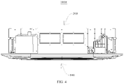
FIG. 4 is a schematic view of a ceiling-embedded air conditioner in an embodiment of the present disclosure. -
- ceiling-embedded
air conditioner 1000 -
panel assembly 100 - panel 1,
air inlet 11,air inlet grille 12 -
panel frame 2,first panel frame 21,second panel frame 22,air outlet 23,air baffle rib 24 -
air guide plate 3,rotation shaft 31, windless-feeling perforation 32 -
body 200. - Embodiments of the present disclosure are further described. Examples of the embodiments are illustrated in the accompanying drawings. Same or similar reference signs represent the same or similar components or components that have the same or similar functions from beginning to end. The embodiments described below with reference to the accompanying drawings are exemplary, are merely used to explain the present disclosure, and cannot be construed as a limitation to the present disclosure.
- In the specification of the present disclosure, it is to be understood that, terms such as "upper," "lower," "vertical," "horizontal," "inner," "outer," "axial," "radial" indicate the orientation or position relationship based on the orientation or position relationship illustrated in the drawings only for convenience of description or for simplifying description of the present disclosure, and do not indicate or imply that the device or element referred to must have a particular orientation or be constructed and operated in a specific orientation, and hence cannot be construed as limitation to the present disclosure. In addition, a feature defined with "first" and "second" may comprise one or more of this feature. In the description of the present disclosure, the term "a plurality of' means two or more than two, unless specified otherwise.
- In the present disclosure, it should be noted that, unless specified otherwise, terms "mounted," "coupled," and "connected," are used broadly, for example, may be fixed connections, detachable connections, or integral connections; may also be mechanical or electrical connections; may also be direct connections or indirect connections via intervening structures; may also be inner communications of two elements, which may be understood by those skilled in the related art according to specific situations.
- The
panel assembly 100 of the ceiling-embedded air conditioner according to embodiments of the present disclosure is described below with reference toFIGs. 1-3 . - As shown in
FIGs. 1 to 3 , thepanel assembly 100 of the ceiling-embedded air conditioner according to the embodiments of the present disclosure includes a panel 1, apanel frame 2 and anair guide plate 3. Thepanel frame 2 is in annular shape, thepanel frame 2 is fitted over the panel 1, thepanel frame 2 is provided with a plurality ofair outlets 23 are spaced apart from each other and surround the panel 1, an appearance surface of thepanel frame 2 is provided with anair baffle rib 24, and theair baffle rib 24 is located on a side of theair outlet 23 away from the panel 1. Theair guide plate 3 is movably arranged at theair outlet 23. - It may be understood that the
panel frame 2 may fix and limit the panel 1 to improve the mounting stability of the panel 1. Thepanel frame 2 may be further defined with a plurality ofair outlets 23 spaced apart from each other, so as to improve air supply effect of thepanel assembly 100. - As shown in
FIG. 2 , the arrangement of theair guide plate 3 may adjust an air supply direction of thepanel assembly 100. For example, theair guide plate 3 may be moved to a direction parallel to a plane where the panel 1 is located, such that thepanel assembly 100 may output air radially. In another example, theair guide plate 3 may be moved to a direction perpendicular to a plane where the panel 1 is located, such that thepanel assembly 100 may output air axially. For example, theair guide plate 3 may be moved to a direction at an acute angle to a plane where the panel 1 is located, such that thepanel assembly 100 may output air laterally. In this way, thepanel assembly 100 has a variety of air-output manners, which may meet multiple needs of users. It should be noted that theair guide plate 3 may be an arc surface, and a positional relationship between theair guide plate 3 and the panel 1 refers to a relationship between a tangent of an inner arc surface of theair guide plate 3 and a plane where the panel 1 is located. Theair guide plate 3 may also be a flat-straight plane, and a positional relationship between theair guide plate 3 and the panel 1 refers to a relationship between a plane where theair guide plate 3 is located and a plane where the panel 1 is located. - During practical use, when a short-time use is needed, user may choose a lateral air-output mode or axial air-output mode, such that the supplied airflow is close to the user as much as possible, thereby quickly providing a comfortable temperature for the user. When a long-time use is needed by the user, the radial air-outlet mode may be used to reduce user's physical discomfort, such as headache, nasal congestion and other air conditioning diseases, caused by the supplied airflow directly blowing to the user.
- As shown in
FIG. 3 , the arrangement of theair baffle rib 24 may block the airflow at theair outlet 23 from directly blowing to the appearance surface of thepanel frame 2, so as to reduce the condensate water formed on thepanel frame 2, reduce the problems such as water blowing or dripping of the condensate water, and improve the comfort experience for the user. For example, in some panel assemblies, the appearance surface of the panel is a smooth surface, and the airflow at the air outlet directly blows to the appearance surface of the panel frame, which easily causes the condensate water formed on the appearance surface. In thepanel assembly 100 of the present disclosure, theair baffle rib 24 may reduce the occurrence of such situation. In addition, theair baffle rib 24 may also improve mechanical strength of thepanel frame 2 and improve a fatigue life of thepanel assembly 100. - According to the
panel assembly 100 of the ceiling-embedded air conditioner according to the embodiments of the present disclosure, the air supply direction of thepanel assembly 100 may be adjusted through the arrangement of theair guide plate 3, such that thepanel assembly 100 may have a variety of air-output modes and may meet the multiple needs of users. The arrangement of theair baffle rib 24 may block the airflow at theair outlet 23 from blowing directly to the appearance surface of thepanel frame 2, so as to reduce the condensate water easily formed on the appearance surface, reduce the problems such as water blowing or dripping of the condensate water, and improve the comfort experience for the user. In addition, theair baffle rib 24 may also improve the structural strength of thepanel frame 2 and improve the fatigue life of thepanel assembly 100. - In some embodiments, as shown in
FIGs. 1 and2 , thepanel frame 2 includes afirst panel frame 21 and asecond panel frame 22. Thefirst panel frame 21 is in annular shape, thefirst panel frame 21 is fitted over an outer circumference of the panel 1, and a plurality of notches spaced apart from each other are arranged at an outer edge of thefirst panel frame 21. Thesecond panel frame 22 is in annular shape, thesecond panel frame 22 is fitted over an outer circumference of thefirst panel frame 21, theair outlet 23 is defined between an inner wall of each notch and an inner peripheral wall of thesecond panel frame 22, and theair baffle rib 24 is arranged at thesecond panel frame 22. It may be understood that the arrangement of thefirst panel frame 21 may fix and limit the panel 1 and improve the mounting stability of the panel 1. Thefirst panel frame 21 may also be defined with a plurality of notches spaced apart from each other on an outer edge of the first panel frame, so as to improve air volume of the air passing through thefirst panel frame 21 and improve the air supply efficiency of thepanel assembly 100. Moreover, an inner wall of each notch may further guide the flow of airflow. - The arrangement of the
second panel frame 22 may fix and limit thefirst panel frame 21, so as to improve the mounting stability of thefirst panel frame 21. Thesecond panel frame 22 may further guide the flow of airflow, such that the air flows along an inner peripheral wall of thesecond panel frame 22 of thesecond panel frame 22. - In addition, the
panel frame 2 includes thefirst panel frame 21 and thesecond panel frame 22, which may improve the structural strength of thepanel frame 2, facilitate the molding of the panel 1 and help to reduce the cost. - In some embodiments, as shown in
FIG. 1 andFIG. 2 , eachair outlet 23 is provided with at least oneair guide plate 3 rotatable to open and close, and arotation shaft 31 of theair guide plate 3 is located on a side of theair outlet 23 adjacent to the panel 1. It may be understood that theair guide plate 3 may rotate around therotation shaft 31, so as to change an inclined direction of theair guide plate 3 of therotation shaft 31, and then to change the air-output direction of thepanel assembly 100. Therotation shaft 31 is located on the side of theair outlet 23 adjacent to the panel 1, such that when theair guide plate 3 is rotated to be parallel to the plane where the panel 1 is located, thepanel assembly 100 may output air radially, which may reduce the discomfort caused by long time direct blowing to the user. - Of course, in some other embodiments, the
air guide plate 3 may also be arranged to be slidable to open and close, the arrangement may also achieve the above functions, and action manners of theair guide plate 3 is not limited herein. - In some embodiments, as shown in
FIG. 3 , a plurality ofair baffle ribs 24 are spaced apart from each other at a side of theair outlet 23 away from the panel 1. It may be understood that temperature difference between the side of theair outlet 23 away from the panel 1 and the airflow is large, and when the airflow blows to this side, it is easy to form the condensate water. Therefore, the plurality ofair baffle ribs 24, spaced apart from each other, is arranged at this side, so as to block the airflow and reduce the direct blowing of the airflow to this side. - Of course, in some other embodiments, the plurality of spaced
air baffle ribs 24 may also be arranged at a side of theair outlet 23 close to the panel 1, so as to further reduce the water blowing and improve the comfort experience for the user. - Specifically, as shown in
FIG. 3 , a width dimension of the air baffle rib 24 (denoted by L1) is less than or equal to 3mm, and a spacing between adjacent air baffle ribs 24 (denoted by L2) is less than or equal to 5mm. It should be noted that a blocking effect of theair baffle rib 24 on the airflow refers to blocking the airflow from blowing directly to thepanel frame 2, rather than blocking the airflow from flowing out of theair outlet 23. The width dimension of theair baffle rib 24 is less than or equal to 3mm, and the spacing between adjacentair baffle ribs 24 is less than or equal to 5mm. Thus, theair baffle rib 24 may well prevent the airflow from directly blowing to thepanel frame 2, which has little impact on that the airflow flows out of theair outlet 23, so as to reduce a flow loss of the airflow. - In some embodiments, as shown in
FIG. 1 , theair baffle ribs 24 are in annular shape surrounding the panel 1, and theair baffle ribs 24 surrounds an outer side of the plurality ofair outlets 23. In this way, theair baffle ribs 24 may block the airflow at the plurality ofair outlets 23 from blowing directly to thepanel frame 2, reduce the formation of the condensate water as much as possible and improve the user experience. - Optionally, the
air baffle ribs 24 may be arranged continuously or in sections. That is, the baffle splitribs 24 may surround an entire outer side of the panel 1. Theair baffle ribs 24 may also only surround the outer side of the plurality ofair outlets 23, or theair baffle ribs 24 may surround the outer side of the plurality ofair outlets 23 and surround a part of the outer side of the panel 1. - In some embodiments, as shown in
FIGs. 1 and2 , theair guide plate 3 is provided with a windless-feeling perforation 32. It may be understood that during operation, the airflow atair outlet 23 is relatively concentrated and the air speed is relatively large. The arrangement of the windless-feeling perforation 32 may disperse the airflow, reduce intensity of the airflow such that the output air is softer and more uniform. - In some embodiments, as shown in
FIGs. 1 and2 , the panel 1 is provided with anair inlet 11. It may be understood that thepanel frame 2 is fitted over the panel 1, the panel 1 occupies large area, and theair inlet 11 is arranged at the panel 1, which is conducive to improving air volume of input air and improve the air supply efficiency of thepanel assembly 100. - Specifically, as shown in
FIG. 1 andFIG. 2 , the panel 1 is integrated with anair inlet grille 12 at theair inlet 11. It may be understood that the arrangement of theair inlet grille 12 may improve cleanliness of interior of thepanel assembly 100, reduce the entry of dust and other particles carried in the airflow into the interior of the face assembly, so as to improve the service life of thepanel assembly 100. - The
panel assembly 100 of the ceiling-embedded air conditioner according to a specific embodiment of the present disclosure is described below with reference toFIGs. 1-3 . - The
panel assembly 100 of the ceiling-embedded air conditioner according to the embodiments of the present disclosure includes a panel 1, apanel frame 2 and anair guide plate 3. - The panel 1 is provided with an
air inlet 11, and the panel 1 is integrated with anair inlet grille 12 at theair inlet 11. Thepanel frame 2 includes afirst panel frame 21 and asecond panel frame 22. Thefirst panel frame 21 is in annular shape and fitted over an outer circumference of the panel 1, and a plurality of notches spaced apart from each other are provided at an outer edge of thefirst panel frame 21. Thesecond panel frame 22 is in annular shape and fitted over an outer circumference of thefirst panel frame 21, theair outlet 23 is defined between an inner wall of each notch and an inner peripheral wall of thesecond panel frame 22, and twoair baffle ribs 24 are spaced apart from each other and arranged at thesecond panel frame 22. A width dimension ofair baffle rib 24 is less than or equal to 3mm, and a spacing between twoair baffle ribs 24 is less than or equal to 5mm. Anair guide plate 3 is rotatable to open and close at eachair outlet 23, and arotation shaft 31 of theair guide plate 3 is located on a side of theair outlet 23 adjacent to the panel 1. Theair guide plate 3 is provided with a windless-feeling perforation 32. - A ceiling-embedded
air conditioner 1000 according to an embodiment of the present disclosure is described below with reference to the accompanying drawings. - The ceiling-embedded
air conditioner 1000 according to the embodiments of the present disclosure, as shown inFIGs. 2 and4 , includes thepanel assembly 100 of the ceiling-embedded air conditioner according to the above embodiments of the present disclosure. The structure of thepanel assembly 100 has been described in detail above and is not repeated herein. - The ceiling-embedded
air conditioner 1000 according to the embodiments of the present disclosure may adjust the air supply direction of thepanel assembly 100 via the arrangement of theair guide plate 3, such that the ceiling-embeddedair conditioner 1000 may have a variety of air-output modes and may meet the multiple needs of users. The arrangement of theair baffle rib 24 may block the airflow at theair outlet 23 from blowing directly to the appearance surface of thepanel frame 2, so as to reduce the condensate water easily formed on the appearance surface, reduce the problems such as water blowing or dripping of the condensate water, and improve the comfort experience for the user. In addition, theair baffle rib 24 may also improve the mechanical strength of thepanel frame 2 and improve the fatigue life of thepanel assembly 100. - Optionally, as shown in
FIG. 4 , the ceiling-embeddedair conditioner 1000 also includes abody 200 connected to thepanel assembly 100. In this way, thebody 200 may fix and limit thepanel assembly 100 and improve the mounting stability of thepanel assembly 100. Of course, thebody 200 may also provide other structural mounting positions. Other structures here refer to axial flow fans and electric control boxes, which are known to those skilled in the art and is not described in detail herein. - Reference throughout this specification to "one embodiment," "some embodiments," "schematic embodiment," "an example," "a specific example," or "some examples" means that a particular feature, structure, material, or characteristic described in connection with the embodiment or example is included in at least one embodiment or example of the present disclosure. In this specification, exemplary descriptions of aforesaid terms are not necessarily referring to the same embodiment or example. Furthermore, the particular features, structures, materials, or characteristics may be combined in any suitable manner in one or more embodiments or examples.
- Although embodiments of present disclosure have been shown and described above, it should be understood by those skilled in the art that above embodiments are just explanatory, and cannot be construed to limit the present disclosure, changes, modifications, alternatives and variations can be made to the embodiments without departing from the scope of the present disclosure.
Claims (10)
- A panel assembly of a ceiling-embedded air conditioner, comprising:a panel;a panel frame, the panel frame being in annular shape and fitted over the panel, the panel frame being provided with a plurality of air outlets spaced apart from each other and surrounding the panel, an appearance surface of the panel frame being provided with an air baffle rib being located on a side of the air outlet away from the panel; andan air guide plate being movably arranged at the air outlet.
- The panel assembly of the ceiling-embedded air conditioner according to claim 1, wherein the panel frame comprises:a first panel frame in annular shape and fitted over an outer circumference of the panel, and a plurality of notches spaced apart from each other being arranged at an outer edge of the first panel frame; anda second panel frame in annular shape and fitted over an outer circumference of the first panel frame, the air outlet being defined between an inner wall of each notch and an inner peripheral wall of the second panel frame, and the air baffle rib being arranged at the second panel frame.
- The panel assembly of the ceiling-embedded air conditioner according to claim 1 or 2, wherein each air outlet is provided with at least one air guide plate rotatable to open and close, and a rotation shaft of the air guide plate is located on a side of the air outlet adjacent to the panel.
- The panel assembly of the ceiling-embedded air conditioner according to any one of claims 1 to 3, wherein a plurality of air baffle ribs are provided to be spaced apart from each other at a side of the air outlet away from the panel.
- The panel assembly of the ceiling-embedded air conditioner according to claim 4, wherein a width dimension of the air baffle rib is less than or equal to 3 mm, and a spacing between the adjacent air baffle ribs is less than or equal to 5mm.
- The panel assembly of the ceiling-embedded air conditioner according to any one of claims 1 to 5, wherein the air baffle ribs are in a ring shape surrounding the panel, and the air baffle ribs surrounds an outer side of the plurality of air outlets.
- The panel assembly of the ceiling-embedded air conditioner according to any one of claims 1 to 6, wherein the air guide plate is provided with a windless-feeling perforation.
- The panel assembly of the ceiling-embedded air conditioner according to any one of claims 1 to 7, wherein the panel is provided with an air inlet.
- The panel assembly of the ceiling-embedded air conditioner according to claim 8, wherein the panel is integrated with an air inlet grille at the air inlet.
- A ceiling-embedded air conditioner comprising the panel assembly of the ceiling-embedded air conditioner according to any one of claims 1 to 9.
Applications Claiming Priority (2)
| Application Number | Priority Date | Filing Date | Title |
|---|---|---|---|
| CN201921863229.2U CN210861635U (en) | 2019-10-31 | 2019-10-31 | Panel assembly of ceiling machine and ceiling machine with panel assembly |
| PCT/CN2019/120869 WO2021082142A1 (en) | 2019-10-31 | 2019-11-26 | Panel assembly of ceiling-mounted air conditioner, and ceiling-mounted air conditioner provided with same |
Publications (2)
| Publication Number | Publication Date |
|---|---|
| EP4023946A1 true EP4023946A1 (en) | 2022-07-06 |
| EP4023946A4 EP4023946A4 (en) | 2022-10-26 |
Family
ID=71285028
Family Applications (1)
| Application Number | Title | Priority Date | Filing Date |
|---|---|---|---|
| EP19950471.3A Pending EP4023946A4 (en) | 2019-10-31 | 2019-11-26 | Panel assembly of ceiling-mounted air conditioner, and ceiling-mounted air conditioner provided with same |
Country Status (4)
| Country | Link |
|---|---|
| US (1) | US12203675B2 (en) |
| EP (1) | EP4023946A4 (en) |
| CN (1) | CN210861635U (en) |
| WO (1) | WO2021082142A1 (en) |
Families Citing this family (1)
| Publication number | Priority date | Publication date | Assignee | Title |
|---|---|---|---|---|
| CN116379539B (en) * | 2023-05-17 | 2023-10-13 | 南通理工学院 | Soft ventilation fresh air system for intelligent building |
Family Cites Families (17)
| Publication number | Priority date | Publication date | Assignee | Title |
|---|---|---|---|---|
| JP3240854B2 (en) * | 1994-09-26 | 2001-12-25 | 三菱電機株式会社 | Air conditioner outlet |
| JP2000283544A (en) | 1999-03-31 | 2000-10-13 | Fujitsu General Ltd | Ceiling-mounted air conditioner |
| JP3972894B2 (en) * | 2003-11-27 | 2007-09-05 | ダイキン工業株式会社 | Air conditioner |
| EP1589292A1 (en) * | 2004-04-23 | 2005-10-26 | Unico Consumer Products Co., Ltd. | Ceiling-recessed air treatment apparatus |
| JP2007322103A (en) * | 2006-06-05 | 2007-12-13 | Matsushita Electric Ind Co Ltd | Air conditioner |
| KR100782197B1 (en) * | 2006-08-03 | 2007-12-04 | 엘지전자 주식회사 | Air conditioner |
| JP4952775B2 (en) * | 2009-11-05 | 2012-06-13 | ダイキン工業株式会社 | Air conditioner indoor unit |
| CN102313346B (en) * | 2010-06-29 | 2015-04-08 | 珠海格力电器股份有限公司 | Air conditioner indoor unit |
| US10288302B2 (en) * | 2015-03-31 | 2019-05-14 | Fujitsu General Limited | Ceiling-embedded air conditioner with airflow guide vane |
| KR101881907B1 (en) * | 2015-10-23 | 2018-07-27 | 삼성전자주식회사 | Air conditioner and cotrolling method thereof |
| JP2017116120A (en) * | 2015-12-21 | 2017-06-29 | 三菱重工業株式会社 | Control device, air conditioning system including the same, and control method |
| KR102278637B1 (en) * | 2017-04-07 | 2021-07-16 | 엘지전자 주식회사 | Ceiling type air conditioner |
| KR102401787B1 (en) * | 2017-04-28 | 2022-05-26 | 삼성전자주식회사 | Air conditioner |
| CN108006818A (en) * | 2017-11-23 | 2018-05-08 | 广东美的制冷设备有限公司 | Ceiling machine |
| CN107830579A (en) * | 2017-11-23 | 2018-03-23 | 广东美的制冷设备有限公司 | Ceiling machine |
| CN208011911U (en) * | 2018-04-02 | 2018-10-26 | 广东美的制冷设备有限公司 | Ceiling machine and air conditioner |
| EP3842703A4 (en) * | 2018-08-21 | 2022-03-30 | Hitachi-Johnson Controls Air Conditioning, Inc. | Indoor unit for air conditioner |
-
2019
- 2019-10-31 CN CN201921863229.2U patent/CN210861635U/en active Active
- 2019-11-26 WO PCT/CN2019/120869 patent/WO2021082142A1/en not_active Ceased
- 2019-11-26 US US17/765,320 patent/US12203675B2/en active Active
- 2019-11-26 EP EP19950471.3A patent/EP4023946A4/en active Pending
Also Published As
| Publication number | Publication date |
|---|---|
| CN210861635U (en) | 2020-06-26 |
| EP4023946A4 (en) | 2022-10-26 |
| WO2021082142A1 (en) | 2021-05-06 |
| US20220333815A1 (en) | 2022-10-20 |
| US12203675B2 (en) | 2025-01-21 |
Similar Documents
| Publication | Publication Date | Title |
|---|---|---|
| CN103307661B (en) | Vertical air conditioner | |
| CN204880611U (en) | Air guiding device, air outlet device and indoor unit of air conditioner | |
| EP3348841B1 (en) | Volute fan assembly structure and floor-standing air conditioner | |
| WO2017041695A1 (en) | Volute fan assembly structure and floor-standing air conditioner | |
| JP6927302B2 (en) | Air conditioner indoor unit | |
| CN105135527A (en) | Air conditioner indoor unit and control method thereof | |
| CN110081517A (en) | Windy sense regulating device and air conditioner | |
| CN107036168A (en) | Air deflection assemblies and circular ceiling machine | |
| EP4023946A1 (en) | Panel assembly of ceiling-mounted air conditioner, and ceiling-mounted air conditioner provided with same | |
| KR102182899B1 (en) | An AirVent of A Vehicle | |
| CN205047467U (en) | Combination structure of volute fan and vertical air conditioner | |
| CN211119684U (en) | Panel assembly of ceiling machine and ceiling machine with panel assembly | |
| CN210832222U (en) | Air conditioner indoor unit and air conditioner | |
| US12270556B2 (en) | Panel assembly of ceiling-embedded air conditioner and ceiling-embedded air conditioner having the same | |
| CN205047468U (en) | Combination structure of volute fan and vertical air conditioner | |
| CN107939727B (en) | Fan subassembly and have its air conditioner | |
| CN107449037B (en) | Indoor unit of air conditioner | |
| CN206073395U (en) | Air ducting and cabinet air-conditioner | |
| CN105627427A (en) | Wall-mounted type air conditioner | |
| WO2020172940A1 (en) | Air conditioner indoor unit, air conditioner, and control method for air conditioner | |
| WO2021082143A1 (en) | Panel assembly of ceiling-mounted air conditioner and ceiling-mounted air conditioner having panel assembly | |
| CN109539529B (en) | Duct parts, fan duct components and air conditioners | |
| EP3006850B1 (en) | Vertical air-conditioner comprising a vertical air supply apparatus with airflow distribution assembly | |
| CN210889457U (en) | Air duct structure and air conditioner indoor unit with same | |
| CN211575448U (en) | Air duct member and air conditioner having the same |
Legal Events
| Date | Code | Title | Description |
|---|---|---|---|
| STAA | Information on the status of an ep patent application or granted ep patent |
Free format text: STATUS: THE INTERNATIONAL PUBLICATION HAS BEEN MADE |
|
| PUAI | Public reference made under article 153(3) epc to a published international application that has entered the european phase |
Free format text: ORIGINAL CODE: 0009012 |
|
| STAA | Information on the status of an ep patent application or granted ep patent |
Free format text: STATUS: REQUEST FOR EXAMINATION WAS MADE |
|
| 17P | Request for examination filed |
Effective date: 20220329 |
|
| AK | Designated contracting states |
Kind code of ref document: A1 Designated state(s): AL AT BE BG CH CY CZ DE DK EE ES FI FR GB GR HR HU IE IS IT LI LT LU LV MC MK MT NL NO PL PT RO RS SE SI SK SM TR |
|
| REG | Reference to a national code |
Ref country code: DE Ref legal event code: R079 Free format text: PREVIOUS MAIN CLASS: F24F0001000000 Ipc: F24F0001004700 |
|
| A4 | Supplementary search report drawn up and despatched |
Effective date: 20220927 |
|
| RIC1 | Information provided on ipc code assigned before grant |
Ipc: F24F 13/22 20060101ALN20220921BHEP Ipc: F24F 1/0014 20190101ALI20220921BHEP Ipc: F24F 13/14 20060101ALI20220921BHEP Ipc: F24F 1/0047 20190101AFI20220921BHEP |
|
| DAV | Request for validation of the european patent (deleted) | ||
| DAX | Request for extension of the european patent (deleted) | ||
| STAA | Information on the status of an ep patent application or granted ep patent |
Free format text: STATUS: EXAMINATION IS IN PROGRESS |
|
| 17Q | First examination report despatched |
Effective date: 20240711 |