EP4023890A1 - Turbofan - Google Patents
Turbofan Download PDFInfo
- Publication number
- EP4023890A1 EP4023890A1 EP20873016.8A EP20873016A EP4023890A1 EP 4023890 A1 EP4023890 A1 EP 4023890A1 EP 20873016 A EP20873016 A EP 20873016A EP 4023890 A1 EP4023890 A1 EP 4023890A1
- Authority
- EP
- European Patent Office
- Prior art keywords
- pressure
- flow path
- turbofan
- cross
- increase flow
- Prior art date
- Legal status (The legal status is an assumption and is not a legal conclusion. Google has not performed a legal analysis and makes no representation as to the accuracy of the status listed.)
- Pending
Links
Images



Classifications
-
- F—MECHANICAL ENGINEERING; LIGHTING; HEATING; WEAPONS; BLASTING
- F04—POSITIVE - DISPLACEMENT MACHINES FOR LIQUIDS; PUMPS FOR LIQUIDS OR ELASTIC FLUIDS
- F04D—NON-POSITIVE-DISPLACEMENT PUMPS
- F04D29/00—Details, component parts, or accessories
- F04D29/26—Rotors specially for elastic fluids
- F04D29/28—Rotors specially for elastic fluids for centrifugal or helico-centrifugal pumps for radial-flow or helico-centrifugal pumps
- F04D29/281—Rotors specially for elastic fluids for centrifugal or helico-centrifugal pumps for radial-flow or helico-centrifugal pumps for fans or blowers
- F04D29/282—Rotors specially for elastic fluids for centrifugal or helico-centrifugal pumps for radial-flow or helico-centrifugal pumps for fans or blowers the leading edge of each vane being substantially parallel to the rotation axis
-
- F—MECHANICAL ENGINEERING; LIGHTING; HEATING; WEAPONS; BLASTING
- F04—POSITIVE - DISPLACEMENT MACHINES FOR LIQUIDS; PUMPS FOR LIQUIDS OR ELASTIC FLUIDS
- F04D—NON-POSITIVE-DISPLACEMENT PUMPS
- F04D29/00—Details, component parts, or accessories
- F04D29/26—Rotors specially for elastic fluids
- F04D29/28—Rotors specially for elastic fluids for centrifugal or helico-centrifugal pumps for radial-flow or helico-centrifugal pumps
- F04D29/281—Rotors specially for elastic fluids for centrifugal or helico-centrifugal pumps for radial-flow or helico-centrifugal pumps for fans or blowers
-
- F—MECHANICAL ENGINEERING; LIGHTING; HEATING; WEAPONS; BLASTING
- F04—POSITIVE - DISPLACEMENT MACHINES FOR LIQUIDS; PUMPS FOR LIQUIDS OR ELASTIC FLUIDS
- F04D—NON-POSITIVE-DISPLACEMENT PUMPS
- F04D29/00—Details, component parts, or accessories
- F04D29/26—Rotors specially for elastic fluids
- F04D29/28—Rotors specially for elastic fluids for centrifugal or helico-centrifugal pumps for radial-flow or helico-centrifugal pumps
- F04D29/30—Vanes
-
- F—MECHANICAL ENGINEERING; LIGHTING; HEATING; WEAPONS; BLASTING
- F04—POSITIVE - DISPLACEMENT MACHINES FOR LIQUIDS; PUMPS FOR LIQUIDS OR ELASTIC FLUIDS
- F04D—NON-POSITIVE-DISPLACEMENT PUMPS
- F04D1/00—Radial-flow pumps, e.g. centrifugal pumps; Helico-centrifugal pumps
- F04D1/04—Helico-centrifugal pumps
-
- F—MECHANICAL ENGINEERING; LIGHTING; HEATING; WEAPONS; BLASTING
- F04—POSITIVE - DISPLACEMENT MACHINES FOR LIQUIDS; PUMPS FOR LIQUIDS OR ELASTIC FLUIDS
- F04D—NON-POSITIVE-DISPLACEMENT PUMPS
- F04D15/00—Control, e.g. regulation, of pumps, pumping installations or systems
- F04D15/0027—Varying behaviour or the very pump
- F04D15/0038—Varying behaviour or the very pump by varying the effective cross-sectional area of flow through the rotor
-
- F—MECHANICAL ENGINEERING; LIGHTING; HEATING; WEAPONS; BLASTING
- F04—POSITIVE - DISPLACEMENT MACHINES FOR LIQUIDS; PUMPS FOR LIQUIDS OR ELASTIC FLUIDS
- F04D—NON-POSITIVE-DISPLACEMENT PUMPS
- F04D17/00—Radial-flow pumps, e.g. centrifugal pumps; Helico-centrifugal pumps
- F04D17/08—Centrifugal pumps
-
- F—MECHANICAL ENGINEERING; LIGHTING; HEATING; WEAPONS; BLASTING
- F04—POSITIVE - DISPLACEMENT MACHINES FOR LIQUIDS; PUMPS FOR LIQUIDS OR ELASTIC FLUIDS
- F04D—NON-POSITIVE-DISPLACEMENT PUMPS
- F04D17/00—Radial-flow pumps, e.g. centrifugal pumps; Helico-centrifugal pumps
- F04D17/08—Centrifugal pumps
- F04D17/10—Centrifugal pumps for compressing or evacuating
- F04D17/12—Multi-stage pumps
- F04D17/14—Multi-stage pumps with means for changing the flow-path through the stages, e.g. series-parallel, e.g. side-loads
-
- F—MECHANICAL ENGINEERING; LIGHTING; HEATING; WEAPONS; BLASTING
- F04—POSITIVE - DISPLACEMENT MACHINES FOR LIQUIDS; PUMPS FOR LIQUIDS OR ELASTIC FLUIDS
- F04D—NON-POSITIVE-DISPLACEMENT PUMPS
- F04D29/00—Details, component parts, or accessories
- F04D29/26—Rotors specially for elastic fluids
- F04D29/32—Rotors specially for elastic fluids for axial flow pumps
- F04D29/325—Rotors specially for elastic fluids for axial flow pumps for axial flow fans
-
- F—MECHANICAL ENGINEERING; LIGHTING; HEATING; WEAPONS; BLASTING
- F04—POSITIVE - DISPLACEMENT MACHINES FOR LIQUIDS; PUMPS FOR LIQUIDS OR ELASTIC FLUIDS
- F04D—NON-POSITIVE-DISPLACEMENT PUMPS
- F04D29/00—Details, component parts, or accessories
- F04D29/40—Casings; Connections of working fluid
- F04D29/42—Casings; Connections of working fluid for radial or helico-centrifugal pumps
- F04D29/426—Casings; Connections of working fluid for radial or helico-centrifugal pumps especially adapted for liquid pumps
- F04D29/4293—Details of fluid inlet or outlet
-
- F—MECHANICAL ENGINEERING; LIGHTING; HEATING; WEAPONS; BLASTING
- F04—POSITIVE - DISPLACEMENT MACHINES FOR LIQUIDS; PUMPS FOR LIQUIDS OR ELASTIC FLUIDS
- F04D—NON-POSITIVE-DISPLACEMENT PUMPS
- F04D5/00—Pumps with circumferential or transverse flow
- F04D5/002—Regenerative pumps
- F04D5/007—Details of the inlet or outlet
-
- F—MECHANICAL ENGINEERING; LIGHTING; HEATING; WEAPONS; BLASTING
- F05—INDEXING SCHEMES RELATING TO ENGINES OR PUMPS IN VARIOUS SUBCLASSES OF CLASSES F01-F04
- F05D—INDEXING SCHEME FOR ASPECTS RELATING TO NON-POSITIVE-DISPLACEMENT MACHINES OR ENGINES, GAS-TURBINES OR JET-PROPULSION PLANTS
- F05D2210/00—Working fluids
- F05D2210/40—Flow geometry or direction
-
- F—MECHANICAL ENGINEERING; LIGHTING; HEATING; WEAPONS; BLASTING
- F05—INDEXING SCHEMES RELATING TO ENGINES OR PUMPS IN VARIOUS SUBCLASSES OF CLASSES F01-F04
- F05D—INDEXING SCHEME FOR ASPECTS RELATING TO NON-POSITIVE-DISPLACEMENT MACHINES OR ENGINES, GAS-TURBINES OR JET-PROPULSION PLANTS
- F05D2240/00—Components
- F05D2240/20—Rotors
- F05D2240/30—Characteristics of rotor blades, i.e. of any element transforming dynamic fluid energy to or from rotational energy and being attached to a rotor
- F05D2240/301—Cross-sectional characteristics
-
- F—MECHANICAL ENGINEERING; LIGHTING; HEATING; WEAPONS; BLASTING
- F05—INDEXING SCHEMES RELATING TO ENGINES OR PUMPS IN VARIOUS SUBCLASSES OF CLASSES F01-F04
- F05D—INDEXING SCHEME FOR ASPECTS RELATING TO NON-POSITIVE-DISPLACEMENT MACHINES OR ENGINES, GAS-TURBINES OR JET-PROPULSION PLANTS
- F05D2240/00—Components
- F05D2240/20—Rotors
- F05D2240/30—Characteristics of rotor blades, i.e. of any element transforming dynamic fluid energy to or from rotational energy and being attached to a rotor
- F05D2240/303—Characteristics of rotor blades, i.e. of any element transforming dynamic fluid energy to or from rotational energy and being attached to a rotor related to the leading edge of a rotor blade
-
- F—MECHANICAL ENGINEERING; LIGHTING; HEATING; WEAPONS; BLASTING
- F05—INDEXING SCHEMES RELATING TO ENGINES OR PUMPS IN VARIOUS SUBCLASSES OF CLASSES F01-F04
- F05D—INDEXING SCHEME FOR ASPECTS RELATING TO NON-POSITIVE-DISPLACEMENT MACHINES OR ENGINES, GAS-TURBINES OR JET-PROPULSION PLANTS
- F05D2240/00—Components
- F05D2240/20—Rotors
- F05D2240/30—Characteristics of rotor blades, i.e. of any element transforming dynamic fluid energy to or from rotational energy and being attached to a rotor
- F05D2240/304—Characteristics of rotor blades, i.e. of any element transforming dynamic fluid energy to or from rotational energy and being attached to a rotor related to the trailing edge of a rotor blade
-
- F—MECHANICAL ENGINEERING; LIGHTING; HEATING; WEAPONS; BLASTING
- F05—INDEXING SCHEMES RELATING TO ENGINES OR PUMPS IN VARIOUS SUBCLASSES OF CLASSES F01-F04
- F05D—INDEXING SCHEME FOR ASPECTS RELATING TO NON-POSITIVE-DISPLACEMENT MACHINES OR ENGINES, GAS-TURBINES OR JET-PROPULSION PLANTS
- F05D2250/00—Geometry
- F05D2250/50—Inlet or outlet
-
- F—MECHANICAL ENGINEERING; LIGHTING; HEATING; WEAPONS; BLASTING
- F05—INDEXING SCHEMES RELATING TO ENGINES OR PUMPS IN VARIOUS SUBCLASSES OF CLASSES F01-F04
- F05D—INDEXING SCHEME FOR ASPECTS RELATING TO NON-POSITIVE-DISPLACEMENT MACHINES OR ENGINES, GAS-TURBINES OR JET-PROPULSION PLANTS
- F05D2250/00—Geometry
- F05D2250/50—Inlet or outlet
- F05D2250/52—Outlet
Definitions
- the present disclosure relates to a turbofan.
- Patent Document 1 discloses a turbofan.
- the turbofan is provided in an indoor unit of an air conditioner.
- the turbofan includes an end plate and a shroud between which an air flow path is formed.
- the turbofan draws air into the air flow path and expels the drawn air radially outward.
- the cross-sectional area of the air flow path of this turbofan is uniform from the upstream end to the downstream end of the air flow path.
- Patent Document 1 Japanese Unexamined Patent Publication No. H10-153193
- the pressure of the air drawn into the turbofan is increased while the air is passing through the air flow path between the end plate and the shroud. Since the cross-sectional area of the air flow path of the turbofan of Patent Document 1 is uniform from the upstream end to the downstream end of the air flow path, the pressure of the air flowing through the air flow path is increased only by blade members. Thus, the pressure-increase effect of the known turbofan is susceptible to improvement.
- a first aspect of the present disclosure is directed to a turbofan including: a circular end plate (31); a ring-shaped shroud (32) facing the end plate (31); and a plurality of blade members (33) between the end plate (31) and the shroud (32).
- a space between the end plate (31) and the shroud (32) an annular portion where the blade members (33) are provided is a pressure-increase flow path (43), the turbofan causing air to flow from an inner peripheral side to an outer peripheral side of the pressure-increase flow path (43).
- a cross-sectional area of the pressure-increase flow path (43) increasing gradually from an upstream end (43a) toward a downstream end (43b) of the pressure-increase flow path (43).
- the cross-sectional area of the pressure-increase flow path (43) increases gradually from an upstream end (43a) toward a downstream end (43b) of the pressure-increase flow path (43).
- the pressure-increase flow path (43) of this aspect provides the diffuser effect.
- the turbofan (30) of this aspect utilizes both of the pressure-increase effect of the blade members (33) and the diffuser effect of the pressure-increase flow path (43) to increase the pressure of the air flowing through the pressure-increase flow path (43).
- the pressure-increase effect of the turbofan (30) improves.
- a second aspect of the present disclosure is an embodiment of the first aspect.
- an area magnification ratio S N /S 1 that is a value obtained by dividing a cross-sectional area S N of the downstream end (43b) of the pressure-increase flow path (43) by a cross-sectional area S 1 of the upstream end (43a) of the pressure-increase flow path (43) is greater than or equal to 1.2.
- the area magnification ratio S N /S 1 of the pressure-increase flow path (43) is set to be greater than or equal to 1.2.
- a third aspect of the present disclosure is an embodiment of the second aspect.
- the area magnification ratio S N /S 1 of the pressure-increase flow path (43) is less than or equal to 1.55.
- the area magnification ratio S N /S 1 of the pressure-increase flow path (43) is set to be less than or equal to 1.55.
- a fourth aspect of the present disclosure is an embodiment of any one of the first to third aspects.
- a cross section showing an airfoil of each of the blade members (33) is referred to as a target cross section (51)
- a circle passing through a leading edge (52) of the target cross section (51) and centered at a center axis (CX) of the end plate (31) is referred to as a front circle (FC)
- a circle passing through a trailing edge (53) of the target cross section (51) and centered at the center axis (CX) of the end plate (31) is referred to as a rear circle (RC)
- an angle formed at the leading edge (52) of the target cross section (51) by a tangent to a camber line (54) of the target cross section (51) and a tangent to the front circle (FC) is referred to as an inlet angle ⁇ i
- Increasing the rotational speed of the turbofan (30) to compensate for the reduction in the amount of pressure increase of the air leads to an increase in the power required to rotate the turbofan (30).
- the average of the angle ratios of the entirety of the blade member (33) is set to be less than 2.5.
- a fifth aspect of the present disclosure is an embodiment of the fourth aspect.
- the average of the angle ratios ⁇ ⁇ / ⁇ i of the entirety of the blade member (33) is less than or equal to 2.1.
- the average of the angle ratios of the entirety of the blade member (33) is less than or equal to 2.1. This reduces the "slip flow" of air to a small amount.
- the average of the angle ratios of the entirety of the blade member (33) is less than or equal to 2.1, the possibility for the air flow to be separated from the surface of the blade member (33) is reduced even if the air flow velocity of air flowing through the pressure-increase flow path (43) decreases.
- the power required to rotate the turbofan (30) can be reduced to a low level.
- a sixth aspect of the present disclosure is an embodiment of the fourth or fifth aspect.
- the average of the angle ratios ⁇ ⁇ / ⁇ i of the entirety of the blade member (33) is greater than or equal to 1.0.
- the average of the angle ratios of the entirety of each blade member (33) is set to be greater than 1.0.
- a turbofan (30) of this embodiment is provided in an indoor unit (10) of an air conditioner.
- the indoor unit (10) is configured as a ceiling embedded indoor unit.
- the indoor unit (10) is connected to an outdoor unit (not shown) through a connection pipe, thereby forming the air conditioner.
- the indoor unit (10) includes a box-shaped casing (11).
- a decorative panel (13) forming a lower surface of the casing (11) has an inlet (14) and an outlet (15).
- the inlet (14) is formed in a central portion of the decorative panel (13).
- the outlet (15) surrounds the inlet (14).
- the casing (11) houses components, such as a bell mouth (21), the turbofan (30), and an indoor heat exchanger (22).
- the bell mouth (21) is disposed above the inlet (14).
- the turbofan (30) is disposed above the bell mouth (21).
- the turbofan (30) is fixed to a top panel (12) of the casing (11) with a fan motor (23) interposed therebetween.
- the indoor heat exchanger (22) is arranged to surround the turbofan (30).
- Air is drawn into the casing (11) through the inlet (14) when the turbofan (30) is driven by the fan motor (23).
- the air drawn into the casing (11) is drawn through the bell mouth (21) into the turbofan (30).
- the turbofan (30) draws the air from below and expels the air radially outward.
- the air expelled through the turbofan (30) is cooled or heated while passing through the indoor heat exchanger (22).
- the air that has passed through the indoor heat exchanger (22) is expelled through the outlet (15) to the outside of the casing (11).
- the turbofan (30) includes one end plate (31), one shroud (32), and five blade members (33).
- the number of the blade members (33) is merely an example.
- the end plate (31) is a disk-shaped member having a recessed central portion.
- a drive shaft of the fan motor (23) is coupled to the end plate (31).
- the end plate (31) is disposed coaxially with the drive shaft of the fan motor (23).
- the center axis (CX) of the end plate (31) is the rotation center axis of the turbofan (30).
- the center axis (CX) of the end plate (31) substantially coincides with the center axis of the drive shaft of the fan motor.
- the shroud (32) is a ring-shaped member.
- the shroud (32) is spaced apart from, and faces, the end plate (31).
- the shroud (32) is disposed substantially coaxially with the end plate (31).
- the outer diameter of the shroud (32) is generally equal to the outer diameter of the end plate (31).
- the shroud (32) has an inner peripheral edge that projects away from the end plate (31).
- the inner peripheral edge of the shroud (32) defines a fan inlet (41), and the outer peripheral edge of the end plate (31) and the outer peripheral edge of the shroud (32) define a fan outlet (42).
- the blade members (33) are provided between the end plate (31) and the shroud (32).
- the blade members (33) are disposed in a region of the end plate (31) closer to the outer peripheral edge thereof.
- Upper edge portions of the blade members (33) as observed in FIG. 1 are fixed to the end plate (31).
- Lower edge portions of the blade members (33) as observed in FIG. 1 are fixed to the shroud (32).
- the five blade members (33) are arranged at predetermined angular intervals in the circumferential direction of the end plate (31) and the shroud (32). The angular intervals of these five blade members (33) are not regular intervals.
- the leading edge (52) of each blade member (33) located forward in the rotation direction of the turbofan (30) is closer to the center of the end plate (31) than the trailing edge (53) of the blade member (33) located backward in the rotation direction of the turbofan (30) is.
- a portion where the blade members (33) are provided forms a pressure-increase flow path (43).
- the pressure-increase flow path (43) is an annular flow path continuous with the fan outlet (42) of the turbofan (30). Air passing through the turbofan (30) flows through the pressure-increase flow path (43) from the inside toward the outside in the radial direction of the pressure-increase flow path (43).
- the cross-sectional area of the pressure-increase flow path (43) increases gradually from the upstream end (43a) toward the downstream end (43b) of the pressure-increase flow path (43).
- the cross-sectional area of the pressure-increase flow path (43) will be described.
- the cross-sectional area of the pressure-increase flow path (43) is the area of a cross section that intersects with the radial direction of the pressure-increase flow path (43).
- a n represents an optional point on the inner surface (upper surface in FIG. 3 ) of the shroud (32), and B n represents a point located on the inner surface (lower surface in FIG. 3 ) of the end plate (31) and corresponding to the point A n .
- B n represents a point located on the inner surface (lower surface in FIG. 3 ) of the end plate (31) and corresponding to the point A n .
- a circle touching both of the inner surface of the shroud (32) and the inner surface of the end plate (31) and making contact at the point A n is defined as an inscribed circle IC n .
- the point B n is the point of contact between the inner surface of the end plate (31) and the inscribed circle IC n as viewed in the cross section illustrated in FIG. 3 .
- RA n represents the distance from the center axis (CX) of the end plate (31) to the point A n
- RB n represents the distance from the center axis (CX) of the end plate (31) to the point B n .
- the length of the line segment A n B n is defined as the flow path width W n of the pressure-increase flow path (43) corresponding to the point A n .
- n is an integer from 1 to N.
- the cross-sectional area S n of a cross section of the pressure-increase flow path (43) corresponding to the point A n is the area of a figure obtained by rotating the line segment A n B n by 360° around the center axis (CX) of the end plate (31).
- the cross-sectional area S n of the cross section of the pressure-increase flow path (43) corresponding to the point A n is the lateral area of a conical frustum having a top radius of RB n and a base radius of RA n , and is expressed by the following formula.
- S n ⁇ RA n + RB n W n
- the cross section of the pressure-increase flow path (43) corresponding to the point A 1 corresponds to the upstream end (43a) of the pressure-increase flow path (43).
- the line segment A 1 B 1 is a line segment intersecting with the leading edge (52) of the blade member (33) and closest to the center axis (CX) of the end plate (31).
- the cross section of the pressure-increase flow path (43) corresponding to the point A N corresponds to the downstream end (43b) of the pressure-increase flow path (43).
- the line segment A N B N is a line segment intersecting with the trailing edge (53) of the blade member (33) and farthest from the center axis (CX) of the end plate (31).
- the downstream end (43b) of the pressure-increase flow path (43) substantially coincides with the fan outlet (42) of the turbofan (30).
- the cross-sectional area of the pressure-increase flow path (43) increases gradually from the upstream end (43a) toward the downstream end (43b) of the pressure-increase flow path (43).
- the cross-sectional areas S 1 to S 5 respectively corresponding to the points A 1 to A 5 illustrated in FIG. 3 satisfy the relationship of "S 1 ⁇ S 2 ⁇ S 3 ⁇ S 4 ⁇ S 5 .”
- the area magnification ratio S N /S 1 of the pressure-increase flow path (43) of this embodiment that is a value obtained by dividing "the cross-sectional area S N of the downstream end (43b) of the pressure-increase flow path (43)" by "the cross-sectional area S 1 of the upstream end (43a) of the pressure-increase flow path (43)" is greater than or equal to 1.2 and less than or equal to 1.55.
- the area ratio S n /S 1 of the pressure-increase flow path (43) of this embodiment that is a value obtained by dividing "the cross-sectional area S n of the pressure-increase flow path (43) corresponding to the optional point A n " by "the cross-sectional area S 1 of the upstream end (43a) of the pressure-increase flow path (43)" is a value within the hatched region in FIG. 5 .
- M n represents the midpoint of the flow path width W n corresponding to the point A n as viewed in the cross section illustrated in FIG. 3 .
- LM represents the length of a width central line (44) that is a line connecting the midpoints M 1 to M N from the upstream end (43a) to the downstream end (43b) of the pressure-increase flow path (43), and LM n represents the length of a portion of this width central line (44) from the midpoints M 1 to M n .
- the area ratio S n /S 1 of the pressure-increase flow path (43) of this embodiment is a value within the hatched region in FIG. 5 .
- the pressure-increase flow path (43) of this embodiment satisfies the following relationship.
- the plurality of blade members (33) (five in this embodiment) of the turbofan (30) of this embodiment have the same shape. These blade members (33) are provided between the end plate (31) and the shroud (32) each with the same inlet angle ⁇ i and the same outlet angle ⁇ ⁇ as those illustrated in FIG. 6 .
- a target cross section (51) of the blade member (33) illustrated in FIG. 6 is a cross section intersecting with the leading edge (52) and the trailing edge (53) of the blade member (33), and shows an airfoil of the blade member (33).
- the camber line (54) of the target cross section (51) is a line connecting midpoints, in the thickness direction, of the target cross section (51) from the leading edge (52) to the trailing edge (53) of the target cross section (51).
- a circle passing through the leading edge (52) of the target cross section (51) and centered at the center axis (CX) of the end plate (31) is referred to as a front circle (FC).
- a circle passing through the trailing edge (53) of the target cross section (51) and centered at the center axis (CX) of the end plate (31) is referred to as a rear circle (RC).
- the inlet angle ⁇ i of the target cross section (51) is an angle formed by a tangent TL1 to the camber line (54) at the leading edge (52) of the target cross section (51) and a tangent TL2 to the front circle (FC) at the leading edge (52) of the target cross section (51).
- the outlet angle ⁇ ⁇ of the target cross section (51) is an angle formed by a tangent TT1 to the camber line (54) at the trailing edge (53) of the target cross section (51) and a tangent TT2 to the rear circle (RC) at the trailing edge (53) of the target cross section (51).
- the shape of the target cross section (51) of the blade member (33) i.e., the airfoil of the blade member (33)
- the inlet angle ⁇ i and the outlet angle ⁇ ⁇ of the blade member (33) differ according to where to take the target cross section (51).
- a value obtained by dividing the outlet angle ⁇ ⁇ by the inlet angle ⁇ i is referred to as the angle ratio ⁇ ⁇ / ⁇ i .
- the average of the angle ratios ⁇ ⁇ / ⁇ i in the span direction of the blade member (33) is greater than or equal to 1.0 and less than 2.5. In one preferred embodiment, the average of the angle ratios ⁇ ⁇ / ⁇ i is greater than or equal to 1.0 and less than or equal to 2.1.
- the target cross section (51) of each of the blade members (33) will be described with reference to FIG. 7 .
- the blade members (33) may be solid or hollow.
- FIG. 7 shows a meridional plane shape of the blade member (33).
- the edge of the meridional plane shape along the shroud (32) (the edge of the lower end in FIG. 7 ) is divided into a plurality of equal parts to allocate a plurality of points C n .
- the edge of the meridional plane shape along the end plate (31) (the edge of the upper end in FIG. 7 ) is divided into a plurality of equal parts to allocate a plurality of points D n .
- the number of the points D n is equal to the number of the points C n .
- the meridional plane shape of the blade member (33) is the shape of a figure of a revolved projection of the blade member (33) onto a plane including the center axis (CX) of the end plate (31).
- the subscript n is an integer from 1 to N.
- the point En is set on each of line segments C n D n .
- the points En on the line segment CnDn are those provided so that the ratio (HE/HD) of the length HE of the line segment CnEn to the length HD of each line segment C n D n is the same.
- a curve smoothly connecting the points E 1 to E N is referred to as the curve IL.
- a cross section of the blade member (33) taken along a curved plane obtained by rotating this curve IL around the center axis (CX) of the end plate (31) is a target cross section (51) corresponding to the point E n .
- the turbofan (30) of this embodiment when driven to rotate by the fan motor (23), draws air through the fan inlet (41) and expels the drawn air through the fan outlet (42) after increasing the pressure of the drawn air. Air flows into the fan inlet (41) along the direction of the rotation center axis of the turbofan (30). Inside the turbofan (30), the direction of the air flow changes radially outward from the direction of the rotation center axis of the turbofan (30).
- the cross-sectional area of the pressure-increase flow path (43) of this embodiment increases gradually from the upstream end (43a) toward the downstream end (43b) of the pressure-increase flow path (43).
- the total head of the air flowing through the pressure-increase flow path (43) is substantially constant.
- the pressure-increase flow path (43) of this embodiment provides the diffuser effect.
- the blade members (33) are disposed in the pressure-increase flow path (43) of the turbofan (30).
- the blade members (33) increase the pressure of the air due to a change in the air flow velocity in the rotation direction from the leading edge (52) to the trailing edge (53) of each blade member (33) and the difference in circumferential velocity between the leading edge (52) and trailing edge (53) of the blade member (33).
- the blade member (33) provides the pressure-increase effect increasing the air pressure.
- the air flow velocity in the rotation direction is a tangential component of the absolute velocity vector of an air flow between an adjacent pair of the blade members (33) with respect to a circle centered at the center axis (CX).
- the turbofan (30) of this embodiment utilizes the pressure-increase effect of the blade members (33) and the diffuser effect of the pressure-increase flow path (43) to increase the air pressure. It is therefore possible to set the average of the angle ratios ⁇ ⁇ / ⁇ i of each blade member (33) to be relatively smaller, compared to known art, while keeping the amount of pressure increase of air in the turbofan (30) at substantially the same level as in known art. As a result, the "slip flow" of air can be reduced to a small amount; it is thus possible to reduce the possibility that the air flow is apart from the surface of the blade member (33) and is separated in the end. Thus, according to the turbofan (30) of this embodiment, the power consumed by the fan motor (23) in driving the turbofan (30) can be reduced while keeping the amount of pressure increase of air in the turbofan (30) at substantially the same level as in known art.
- the turbofan (30) of this embodiment includes the circular end plate (31), the ring-shaped shroud (32) facing the end plate (31), and the plurality of blade members (33) arranged between the end plate (31) and the shroud (32). Of the space between the end plate (31) and the shroud (32), the annular portion where the blade members (33) are provided forms the pressure-increase flow path (43).
- the turbofan (30) causes air to flow from the inner peripheral side to the outer peripheral side of the pressure-increase flow path (43).
- the cross-sectional area of the pressure-increase flow path (43) increases gradually from the upstream end (43a) toward the downstream end (43b) of the pressure-increase flow path (43).
- the cross-sectional area of the pressure-increase flow path (43) increases gradually from the upstream end (43a) toward the downstream end (43b) of the pressure-increase flow path (43).
- the pressure-increase flow path (43) of the turbofan (30) of this embodiment provides the diffuser effect.
- the turbofan (30) of this embodiment utilizes both of the pressure-increase effect of the blade members (33) and the diffuser effect of the pressure-increase flow path (43) to increase the pressure of the air flowing through the pressure-increase flow path (43).
- the pressure-increase effect of the turbofan (30) improves.
- the area magnification ratio S N /S 1 that is a value obtained by dividing the cross-sectional area S N of the downstream end (43b) of the pressure-increase flow path (43) by the cross-sectional area S 1 of the upstream end (43a) of the pressure-increase flow path (43) is greater than or equal to 1.2.
- the area magnification ratio S N /S 1 of the pressure-increase flow path (43) is set to be greater than or equal to 1.2 to ensure the diffuser effect of the pressure-increase flow path (43).
- the area magnification ratio S N /S 1 of the pressure-increase flow path (43) is less than or equal to 1.55.
- the area magnification ratio S N /S 1 of the pressure-increase flow path (43) is set to be less than or equal to 1.55 to reduce the power consumed by the fan motor (23) in driving the turbofan (30).
- the cross section showing the airfoil of the blade member (33) is referred to as the target cross section (51).
- a circle passing through the leading edge (52) of the target cross section (51) and centered at the center axis (CX) of the end plate (31) is referred to as the front circle (FC).
- a circle passing through the trailing edge (53) of the target cross section (51) and centered at the center axis (CX) of the end plate (31) is referred to as the rear circle (RC).
- the angle formed at the leading edge (52) of the target cross section (51) by the tangent to the camber line (54) of the target cross section (51) and the tangent to the front circle (FC) is referred to as the inlet angle ⁇ i .
- the angle formed at the trailing edge (53) of the target cross section (51) by the tangent to the camber line (54) of the target cross section (51) and the tangent to the rear circle (RC) is referred to as the outlet angle ⁇ ⁇ .
- a value obtained by dividing the outlet angle ⁇ ⁇ by the inlet angle ⁇ i is referred to as the angle ratio ⁇ ⁇ / ⁇ i .
- the average of the angle ratios ⁇ ⁇ / ⁇ i of the entirety of each blade member (33) is less than 2.5.
- the "slip flow” is the phenomenon where the direction of the air flow flowing out of the blade member (33) slips in the direction opposite to the direction of revolution of the blade member (33) with respect to the direction along the surface of the blade member (33).
- the larger amount of this "slip flow” makes a larger angle between the direction of the air flow flowing out of the trailing edge (53) of the blade member (33) and the direction of the trailing edge (53) of the blade member (33).
- the mixing loss increases, and the amount of pressure increase of air decreases.
- Increasing the rotational speed of the turbofan (30) to compensate for the reduction in the amount of pressure increase of the air leads to an increase in the power required to rotate the turbofan (30).
- the average of the angle ratios of the entirety of each blade member (33) is set to be less than 2.5 to reduce the power consumed by the fan motor (23) in driving the turbofan (30).
- the average of the angle ratios ⁇ ⁇ / ⁇ i of the entirety of each blade member (33) is less than or equal to 2.1.
- the amount of "slip flow” can thus be reduced to a small amount.
- the possibility for the air flow to be apart from the surface of the blade member (33) and separated in the end is reduced even if the air flow velocity of air flowing through the pressure-increase flow path (43) decreases.
- the power consumed by the fan motor (23) in rotating the turbofan (30) can be reduced to a low level.
- the average of the angle ratios ⁇ ⁇ / ⁇ i of the entirety of each blade member (33) is greater than or equal to 1.0.
- the average of the angle ratios of the entirety of each blade member (33) is set to be greater than 1.0 to ensure the pressure-increase effect of the turbofan (30).
- the turbofan (30) of this embodiment may be provided in a device other than the indoor unit (10) of the air conditioner.
- the application of the turbofan (30) described herein is merely an example.
- the present disclosure is useful for a turbofan.
Landscapes
- Engineering & Computer Science (AREA)
- Mechanical Engineering (AREA)
- General Engineering & Computer Science (AREA)
- Structures Of Non-Positive Displacement Pumps (AREA)
Abstract
Description
- The present disclosure relates to a turbofan.
-
Patent Document 1 discloses a turbofan. The turbofan is provided in an indoor unit of an air conditioner. The turbofan includes an end plate and a shroud between which an air flow path is formed. The turbofan draws air into the air flow path and expels the drawn air radially outward. The cross-sectional area of the air flow path of this turbofan is uniform from the upstream end to the downstream end of the air flow path. - Patent Document 1:
Japanese Unexamined Patent Publication No. H10-153193 - The pressure of the air drawn into the turbofan is increased while the air is passing through the air flow path between the end plate and the shroud. Since the cross-sectional area of the air flow path of the turbofan of
Patent Document 1 is uniform from the upstream end to the downstream end of the air flow path, the pressure of the air flowing through the air flow path is increased only by blade members. Thus, the pressure-increase effect of the known turbofan is susceptible to improvement. - It is an object of the present disclosure to improve the pressure-increase effect of a turbofan.
- A first aspect of the present disclosure is directed to a turbofan including: a circular end plate (31); a ring-shaped shroud (32) facing the end plate (31); and a plurality of blade members (33) between the end plate (31) and the shroud (32). Of a space between the end plate (31) and the shroud (32), an annular portion where the blade members (33) are provided is a pressure-increase flow path (43), the turbofan causing air to flow from an inner peripheral side to an outer peripheral side of the pressure-increase flow path (43). A cross-sectional area of the pressure-increase flow path (43) increasing gradually from an upstream end (43a) toward a downstream end (43b) of the pressure-increase flow path (43).
- According to the first aspect, the cross-sectional area of the pressure-increase flow path (43) increases gradually from an upstream end (43a) toward a downstream end (43b) of the pressure-increase flow path (43). Thus, in the course of passage of air through the pressure-increase flow path (43), the air flow velocity decreases gradually, which causes the air pressure to increase gradually. As can be seen, the pressure-increase flow path (43) of this aspect provides the diffuser effect. Thus, the turbofan (30) of this aspect utilizes both of the pressure-increase effect of the blade members (33) and the diffuser effect of the pressure-increase flow path (43) to increase the pressure of the air flowing through the pressure-increase flow path (43). As a result, the pressure-increase effect of the turbofan (30) improves.
- A second aspect of the present disclosure is an embodiment of the first aspect. In the second aspect, an area magnification ratio SN/S1 that is a value obtained by dividing a cross-sectional area SN of the downstream end (43b) of the pressure-increase flow path (43) by a cross-sectional area S1 of the upstream end (43a) of the pressure-increase flow path (43) is greater than or equal to 1.2.
- If the area magnification ratio of the pressure-increase flow path (43) is too low, the diffuser effect of the pressure-increase flow path (43) is too low to increase the air pressure to an adequate level. Thus, according to the second aspect, the area magnification ratio SN/S1 of the pressure-increase flow path (43) is set to be greater than or equal to 1.2.
- A third aspect of the present disclosure is an embodiment of the second aspect. In the third aspect, the area magnification ratio SN/S1 of the pressure-increase flow path (43) is less than or equal to 1.55.
- If the area magnification ratio of the pressure-increase flow path (43) is too high, the air flow velocity of air flowing through the pressure-increase flow path (43) decreases too much, which causes separation of the air flow and results in an increase in power required to rotate the turbofan (30). Thus, according to the third aspect, the area magnification ratio SN/S1 of the pressure-increase flow path (43) is set to be less than or equal to 1.55.
- A fourth aspect of the present disclosure is an embodiment of any one of the first to third aspects. In the fourth aspect, a cross section showing an airfoil of each of the blade members (33) is referred to as a target cross section (51), a circle passing through a leading edge (52) of the target cross section (51) and centered at a center axis (CX) of the end plate (31) is referred to as a front circle (FC), a circle passing through a trailing edge (53) of the target cross section (51) and centered at the center axis (CX) of the end plate (31) is referred to as a rear circle (RC), an angle formed at the leading edge (52) of the target cross section (51) by a tangent to a camber line (54) of the target cross section (51) and a tangent to the front circle (FC) is referred to as an inlet angle θi, an angle formed at the trailing edge (53) of the target cross section (51) by a tangent to the camber line (54) of the target cross section (51) and a tangent to the rear circle (RC) is referred to as an outlet angle θο, a value obtained by dividing the outlet angle θο by the inlet angle θi is referred to as an angle ratio θο/θi, and an average of the angle ratios θο/θi of an entirety of the blade member (33) is less than 2.5.
- The higher the angle ratio θο/θi of the blade member (33) is, the larger the amount of "slip flow" of air becomes. This reduces the amount of pressure increase of the air. Increasing the rotational speed of the turbofan (30) to compensate for the reduction in the amount of pressure increase of the air leads to an increase in the power required to rotate the turbofan (30). If the angle ratio θο/θi of the blade member (33) is too high, the direction of the air flow along the blade member (33) changes greatly, resulting in higher possibility for the air flow to be apart from the surface of the blade member (33) and separated in the end. Separation of the air flow from the surface of the blade member (33) results in an increase in power required to rotate the turbofan (30). Thus, according to the fourth aspect, the average of the angle ratios of the entirety of the blade member (33) is set to be less than 2.5.
- A fifth aspect of the present disclosure is an embodiment of the fourth aspect. In the fifth aspect, the average of the angle ratios θο/θi of the entirety of the blade member (33) is less than or equal to 2.1.
- According to the fifth aspect, the average of the angle ratios of the entirety of the blade member (33) is less than or equal to 2.1. This reduces the "slip flow" of air to a small amount. In addition, since the average of the angle ratios of the entirety of the blade member (33) is less than or equal to 2.1, the possibility for the air flow to be separated from the surface of the blade member (33) is reduced even if the air flow velocity of air flowing through the pressure-increase flow path (43) decreases. Thus, according to this aspect, the power required to rotate the turbofan (30) can be reduced to a low level.
- A sixth aspect of the present disclosure is an embodiment of the fourth or fifth aspect. In the sixth aspect, the average of the angle ratios θο/θi of the entirety of the blade member (33) is greater than or equal to 1.0.
- If the average of the angle ratios of the entirety of each blade member (33) is too low, the pressure-increase effect of the blade member (33) may be so low that the pressure-increase effect of the turbofan (30) may be insufficient. Thus, according to the sixth aspect, the average of the angle ratios of the entirety of the blade member (33) is set to be greater than 1.0.
-
-
FIG. 1 is a schematic cross-sectional view of an indoor unit including a turbofan. -
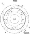
FIG. 2 is a bottom view of the turbofan provided in the indoor unit illustrated inFIG. 1 . -
FIG. 3 is a cross-sectional view illustrating a cross section of the turbofan including the rotation center axis of the turbofan. -
FIG. 4 is a diagram for illustrating the shape of a cross section of a pressure-increase flow path. -
FIG. 5 is a graph showing variations in the cross-sectional area of the pressure-increase flow path from the upstream end to the downstream end of the pressure-increase flow path. -
FIG. 6 is a cross-sectional view illustrating a target cross section of a blade member. -
FIG. 7 is a cross-sectional view illustrating a cross section of the turbofan including the rotation center axis of the turbofan. - Embodiments of the present invention will be described in detail with reference to the drawings. A turbofan (30) of this embodiment is provided in an indoor unit (10) of an air conditioner.
- As illustrated in
FIG. 1 , the indoor unit (10) is configured as a ceiling embedded indoor unit. The indoor unit (10) is connected to an outdoor unit (not shown) through a connection pipe, thereby forming the air conditioner. - The indoor unit (10) includes a box-shaped casing (11). A decorative panel (13) forming a lower surface of the casing (11) has an inlet (14) and an outlet (15). The inlet (14) is formed in a central portion of the decorative panel (13). The outlet (15) surrounds the inlet (14).
- The casing (11) houses components, such as a bell mouth (21), the turbofan (30), and an indoor heat exchanger (22). The bell mouth (21) is disposed above the inlet (14). The turbofan (30) is disposed above the bell mouth (21). The turbofan (30) is fixed to a top panel (12) of the casing (11) with a fan motor (23) interposed therebetween. The indoor heat exchanger (22) is arranged to surround the turbofan (30).
- Air is drawn into the casing (11) through the inlet (14) when the turbofan (30) is driven by the fan motor (23). The air drawn into the casing (11) is drawn through the bell mouth (21) into the turbofan (30). The turbofan (30) draws the air from below and expels the air radially outward. The air expelled through the turbofan (30) is cooled or heated while passing through the indoor heat exchanger (22). The air that has passed through the indoor heat exchanger (22) is expelled through the outlet (15) to the outside of the casing (11).
- As illustrated in
FIGS. 1 and2 , the turbofan (30) includes one end plate (31), one shroud (32), and five blade members (33). The number of the blade members (33) is merely an example. - The end plate (31) is a disk-shaped member having a recessed central portion. A drive shaft of the fan motor (23) is coupled to the end plate (31). The end plate (31) is disposed coaxially with the drive shaft of the fan motor (23). The center axis (CX) of the end plate (31) is the rotation center axis of the turbofan (30). The center axis (CX) of the end plate (31) substantially coincides with the center axis of the drive shaft of the fan motor.
- The shroud (32) is a ring-shaped member. The shroud (32) is spaced apart from, and faces, the end plate (31). The shroud (32) is disposed substantially coaxially with the end plate (31). The outer diameter of the shroud (32) is generally equal to the outer diameter of the end plate (31). The shroud (32) has an inner peripheral edge that projects away from the end plate (31). In the turbofan (30), the inner peripheral edge of the shroud (32) defines a fan inlet (41), and the outer peripheral edge of the end plate (31) and the outer peripheral edge of the shroud (32) define a fan outlet (42).
- The blade members (33) are provided between the end plate (31) and the shroud (32). The blade members (33) are disposed in a region of the end plate (31) closer to the outer peripheral edge thereof. Upper edge portions of the blade members (33) as observed in
FIG. 1 are fixed to the end plate (31). Lower edge portions of the blade members (33) as observed inFIG. 1 are fixed to the shroud (32). As illustrated inFIG. 2 , the five blade members (33) are arranged at predetermined angular intervals in the circumferential direction of the end plate (31) and the shroud (32). The angular intervals of these five blade members (33) are not regular intervals. The leading edge (52) of each blade member (33) located forward in the rotation direction of the turbofan (30) is closer to the center of the end plate (31) than the trailing edge (53) of the blade member (33) located backward in the rotation direction of the turbofan (30) is. - As illustrated in
FIG. 3 , of a space between the end plate (31) and the shroud (32) of the turbofan (30) of this embodiment, a portion where the blade members (33) are provided forms a pressure-increase flow path (43). The pressure-increase flow path (43) is an annular flow path continuous with the fan outlet (42) of the turbofan (30). Air passing through the turbofan (30) flows through the pressure-increase flow path (43) from the inside toward the outside in the radial direction of the pressure-increase flow path (43). According to the turbofan (30) of this embodiment, the cross-sectional area of the pressure-increase flow path (43) increases gradually from the upstream end (43a) toward the downstream end (43b) of the pressure-increase flow path (43). - The cross-sectional area of the pressure-increase flow path (43) will be described. The cross-sectional area of the pressure-increase flow path (43) is the area of a cross section that intersects with the radial direction of the pressure-increase flow path (43).
- As viewed in the cross section illustrated in
FIG. 3 , An represents an optional point on the inner surface (upper surface inFIG. 3 ) of the shroud (32), and Bn represents a point located on the inner surface (lower surface inFIG. 3 ) of the end plate (31) and corresponding to the point An. Here, a circle touching both of the inner surface of the shroud (32) and the inner surface of the end plate (31) and making contact at the point An is defined as an inscribed circle ICn. The point Bn is the point of contact between the inner surface of the end plate (31) and the inscribed circle ICn as viewed in the cross section illustrated inFIG. 3 . - As illustrated in
FIG. 4 , RAn represents the distance from the center axis (CX) of the end plate (31) to the point An, and RBn represents the distance from the center axis (CX) of the end plate (31) to the point Bn. The length of the line segment AnBn is defined as the flow path width Wn of the pressure-increase flow path (43) corresponding to the point An. - The subscript n is an integer from 1 to N. The subscript is n = 1 at the upstream end (43a) of the pressure-increase flow path (43), and n = N at the downstream end (43b) of the pressure-increase flow path (43).
FIG. 3 shows the state where N = 5. - The cross-sectional area Sn of a cross section of the pressure-increase flow path (43) corresponding to the point An is the area of a figure obtained by rotating the line segment AnBn by 360° around the center axis (CX) of the end plate (31). As illustrated in
FIG. 4 , the cross-sectional area Sn of the cross section of the pressure-increase flow path (43) corresponding to the point An is the lateral area of a conical frustum having a top radius of RBn and a base radius of RAn, and is expressed by the following formula.
- The cross section of the pressure-increase flow path (43) corresponding to the point A1 (specifically, a figure obtained by rotating the line segment A1B1 by 360° around the center axis (CX) of the end plate (31)) corresponds to the upstream end (43a) of the pressure-increase flow path (43). The line segment A1B1 is a line segment intersecting with the leading edge (52) of the blade member (33) and closest to the center axis (CX) of the end plate (31). The cross section of the pressure-increase flow path (43) corresponding to the point AN (specifically, a figure obtained by rotating the line segment ANBN by 360° around the center axis (CX) of the end plate (31)) corresponds to the downstream end (43b) of the pressure-increase flow path (43). The line segment ANBN is a line segment intersecting with the trailing edge (53) of the blade member (33) and farthest from the center axis (CX) of the end plate (31). The downstream end (43b) of the pressure-increase flow path (43) substantially coincides with the fan outlet (42) of the turbofan (30).
- As described above, the cross-sectional area of the pressure-increase flow path (43) increases gradually from the upstream end (43a) toward the downstream end (43b) of the pressure-increase flow path (43). Thus, the cross-sectional areas S1 to S5 respectively corresponding to the points A1 to A5 illustrated in
FIG. 3 satisfy the relationship of "S1 < S2 < S3 < S4 < S5." - The area magnification ratio SN/S1 of the pressure-increase flow path (43) of this embodiment that is a value obtained by dividing "the cross-sectional area SN of the downstream end (43b) of the pressure-increase flow path (43)" by "the cross-sectional area S1 of the upstream end (43a) of the pressure-increase flow path (43)" is greater than or equal to 1.2 and less than or equal to 1.55.
- The area ratio Sn/S1 of the pressure-increase flow path (43) of this embodiment that is a value obtained by dividing "the cross-sectional area Sn of the pressure-increase flow path (43) corresponding to the optional point An" by "the cross-sectional area S1 of the upstream end (43a) of the pressure-increase flow path (43)" is a value within the hatched region in
FIG. 5 . - Here, Mn represents the midpoint of the flow path width Wn corresponding to the point An as viewed in the cross section illustrated in
FIG. 3 . LM represents the length of a width central line (44) that is a line connecting the midpoints M1 to MN from the upstream end (43a) to the downstream end (43b) of the pressure-increase flow path (43), and LMn represents the length of a portion of this width central line (44) from the midpoints M1 to Mn. As described above, the area ratio Sn/S1 of the pressure-increase flow path (43) of this embodiment is a value within the hatched region inFIG. 5 . In other words, the pressure-increase flow path (43) of this embodiment satisfies the following relationship.
- The inlet angle θi and the outlet angle θο of each blade member (33) will be described with reference to
FIG. 6 . - The plurality of blade members (33) (five in this embodiment) of the turbofan (30) of this embodiment have the same shape. These blade members (33) are provided between the end plate (31) and the shroud (32) each with the same inlet angle θi and the same outlet angle θο as those illustrated in
FIG. 6 . - A target cross section (51) of the blade member (33) illustrated in
FIG. 6 is a cross section intersecting with the leading edge (52) and the trailing edge (53) of the blade member (33), and shows an airfoil of the blade member (33). The camber line (54) of the target cross section (51) is a line connecting midpoints, in the thickness direction, of the target cross section (51) from the leading edge (52) to the trailing edge (53) of the target cross section (51). A circle passing through the leading edge (52) of the target cross section (51) and centered at the center axis (CX) of the end plate (31) is referred to as a front circle (FC). A circle passing through the trailing edge (53) of the target cross section (51) and centered at the center axis (CX) of the end plate (31) is referred to as a rear circle (RC). - The inlet angle θi of the target cross section (51) is an angle formed by a tangent TL1 to the camber line (54) at the leading edge (52) of the target cross section (51) and a tangent TL2 to the front circle (FC) at the leading edge (52) of the target cross section (51). The outlet angle θο of the target cross section (51) is an angle formed by a tangent TT1 to the camber line (54) at the trailing edge (53) of the target cross section (51) and a tangent TT2 to the rear circle (RC) at the trailing edge (53) of the target cross section (51).
- The shape of the target cross section (51) of the blade member (33) (i.e., the airfoil of the blade member (33)) varies in the span direction of the blade member (33) (the direction along the leading edge (52) or the trailing edge (53)). Thus, the inlet angle θi and the outlet angle θο of the blade member (33) differ according to where to take the target cross section (51). A value obtained by dividing the outlet angle θο by the inlet angle θi is referred to as the angle ratio θο/θi. In each of the blade members (33) of the turbofan (30) of this embodiment, the average of the angle ratios θο/θi in the span direction of the blade member (33) is greater than or equal to 1.0 and less than 2.5. In one preferred embodiment, the average of the angle ratios θο/θi is greater than or equal to 1.0 and less than or equal to 2.1.
- The target cross section (51) of each of the blade members (33) will be described with reference to
FIG. 7 . The blade members (33) may be solid or hollow. -
FIG. 7 shows a meridional plane shape of the blade member (33). The edge of the meridional plane shape along the shroud (32) (the edge of the lower end inFIG. 7 ) is divided into a plurality of equal parts to allocate a plurality of points Cn. The edge of the meridional plane shape along the end plate (31) (the edge of the upper end inFIG. 7 ) is divided into a plurality of equal parts to allocate a plurality of points Dn. The number of the points Dn is equal to the number of the points Cn. The meridional plane shape of the blade member (33) is the shape of a figure of a revolved projection of the blade member (33) onto a plane including the center axis (CX) of the end plate (31). - The subscript n is an integer from 1 to N. The subscript n is n = 1 on the leading edge (52) and n = N on the trailing edge (53) on each of the edge along the shroud (32) and the edge along the end plate (31) of the meridional plane shape of the blade member (33) illustrated in
FIG. 7. FIG. 7 shows a case where N = 5 (specifically, a case where the upper and lower edges of the meridional plane shape of the blade member (33) are each divided into four equal parts). - The point En is set on each of line segments CnDn. The points En on the line segment CnDn are those provided so that the ratio (HE/HD) of the length HE of the line segment CnEn to the length HD of each line segment CnDn is the same. A curve smoothly connecting the points E1 to EN is referred to as the curve IL. A cross section of the blade member (33) taken along a curved plane obtained by rotating this curve IL around the center axis (CX) of the end plate (31) is a target cross section (51) corresponding to the point En.
- The turbofan (30) of this embodiment, when driven to rotate by the fan motor (23), draws air through the fan inlet (41) and expels the drawn air through the fan outlet (42) after increasing the pressure of the drawn air. Air flows into the fan inlet (41) along the direction of the rotation center axis of the turbofan (30). Inside the turbofan (30), the direction of the air flow changes radially outward from the direction of the rotation center axis of the turbofan (30).
- Air flowing through the inside of the turbofan (30) flows into the pressure-increase flow path (43), and flows from the upstream end (43a) toward the downstream end (43b) of the pressure-increase flow path (43). The cross-sectional area of the pressure-increase flow path (43) of this embodiment increases gradually from the upstream end (43a) toward the downstream end (43b) of the pressure-increase flow path (43). Thus, in the course of passage of air through the pressure-increase flow path (43), the air velocity decreases gradually, whereas the air pressure increases gradually. The total head of the air flowing through the pressure-increase flow path (43) is substantially constant. Thus, if the air velocity decreases, and hence the velocity head decreases, the pressure head increases by the decrement of the velocity head. As a result, the air pressure increases. As can be seen, the pressure-increase flow path (43) of this embodiment provides the diffuser effect.
- The blade members (33) are disposed in the pressure-increase flow path (43) of the turbofan (30). The blade members (33) increase the pressure of the air due to a change in the air flow velocity in the rotation direction from the leading edge (52) to the trailing edge (53) of each blade member (33) and the difference in circumferential velocity between the leading edge (52) and trailing edge (53) of the blade member (33). In this manner, the blade member (33) provides the pressure-increase effect increasing the air pressure. The air flow velocity in the rotation direction is a tangential component of the absolute velocity vector of an air flow between an adjacent pair of the blade members (33) with respect to a circle centered at the center axis (CX).
- The turbofan (30) of this embodiment utilizes the pressure-increase effect of the blade members (33) and the diffuser effect of the pressure-increase flow path (43) to increase the air pressure. It is therefore possible to set the average of the angle ratios θο/θi of each blade member (33) to be relatively smaller, compared to known art, while keeping the amount of pressure increase of air in the turbofan (30) at substantially the same level as in known art. As a result, the "slip flow" of air can be reduced to a small amount; it is thus possible to reduce the possibility that the air flow is apart from the surface of the blade member (33) and is separated in the end. Thus, according to the turbofan (30) of this embodiment, the power consumed by the fan motor (23) in driving the turbofan (30) can be reduced while keeping the amount of pressure increase of air in the turbofan (30) at substantially the same level as in known art.
- The turbofan (30) of this embodiment includes the circular end plate (31), the ring-shaped shroud (32) facing the end plate (31), and the plurality of blade members (33) arranged between the end plate (31) and the shroud (32). Of the space between the end plate (31) and the shroud (32), the annular portion where the blade members (33) are provided forms the pressure-increase flow path (43). The turbofan (30) causes air to flow from the inner peripheral side to the outer peripheral side of the pressure-increase flow path (43). In the turbofan (30), the cross-sectional area of the pressure-increase flow path (43) increases gradually from the upstream end (43a) toward the downstream end (43b) of the pressure-increase flow path (43).
- According to the turbofan (30) of this embodiment, the cross-sectional area of the pressure-increase flow path (43) increases gradually from the upstream end (43a) toward the downstream end (43b) of the pressure-increase flow path (43). Thus, in the course of passage of air through the pressure-increase flow path (43), the air flow velocity decreases gradually, which causes the air pressure to increase gradually. As can be seen, the pressure-increase flow path (43) of the turbofan (30) of this embodiment provides the diffuser effect. Thus, the turbofan (30) of this embodiment utilizes both of the pressure-increase effect of the blade members (33) and the diffuser effect of the pressure-increase flow path (43) to increase the pressure of the air flowing through the pressure-increase flow path (43). As a result, the pressure-increase effect of the turbofan (30) improves.
- In the turbofan (30) of this embodiment, the area magnification ratio SN/S1 that is a value obtained by dividing the cross-sectional area SN of the downstream end (43b) of the pressure-increase flow path (43) by the cross-sectional area S1 of the upstream end (43a) of the pressure-increase flow path (43) is greater than or equal to 1.2.
- If the area magnification ratio of the pressure-increase flow path (43) is too low, the diffuser effect of the pressure-increase flow path (43) is too low to increase the air pressure to an adequate level. Thus, according to the turbofan (30) of this embodiment, the area magnification ratio SN/S1 of the pressure-increase flow path (43) is set to be greater than or equal to 1.2 to ensure the diffuser effect of the pressure-increase flow path (43).
- According to the turbofan (30) of this embodiment, the area magnification ratio SN/S1 of the pressure-increase flow path (43) is less than or equal to 1.55.
- If the area magnification ratio of the pressure-increase flow path (43) is too high, the air flow velocity of air flowing through the pressure-increase flow path (43) decreases too much, resulting in higher possibility for the air flow to be separated from the surfaces of the end plate (31), the shroud (32), and the blade members (33). Such separation of the air flow results in an increase in power required to rotate the turbofan (30). Thus, according to the turbofan (30) of this embodiment, the area magnification ratio SN/S1 of the pressure-increase flow path (43) is set to be less than or equal to 1.55 to reduce the power consumed by the fan motor (23) in driving the turbofan (30).
- The cross section showing the airfoil of the blade member (33) is referred to as the target cross section (51). A circle passing through the leading edge (52) of the target cross section (51) and centered at the center axis (CX) of the end plate (31) is referred to as the front circle (FC). A circle passing through the trailing edge (53) of the target cross section (51) and centered at the center axis (CX) of the end plate (31) is referred to as the rear circle (RC). The angle formed at the leading edge (52) of the target cross section (51) by the tangent to the camber line (54) of the target cross section (51) and the tangent to the front circle (FC) is referred to as the inlet angle θi. The angle formed at the trailing edge (53) of the target cross section (51) by the tangent to the camber line (54) of the target cross section (51) and the tangent to the rear circle (RC) is referred to as the outlet angle θο. A value obtained by dividing the outlet angle θο by the inlet angle θi is referred to as the angle ratio θο/θi. In the turbofan (30) of this embodiment, the average of the angle ratios θο/θi of the entirety of each blade member (33) is less than 2.5.
- The higher the angle ratio θο/θi of the blade member (33) is, the more easily a "slip flow" of air occurs. The "slip flow" is the phenomenon where the direction of the air flow flowing out of the blade member (33) slips in the direction opposite to the direction of revolution of the blade member (33) with respect to the direction along the surface of the blade member (33). The larger amount of this "slip flow" makes a larger angle between the direction of the air flow flowing out of the trailing edge (53) of the blade member (33) and the direction of the trailing edge (53) of the blade member (33). As a result, the mixing loss increases, and the amount of pressure increase of air decreases. Increasing the rotational speed of the turbofan (30) to compensate for the reduction in the amount of pressure increase of the air leads to an increase in the power required to rotate the turbofan (30).
- If the angle ratio θο/θi of the blade member (33) is too high, the direction of the air flow along the blade member (33) changes greatly, resulting in higher possibility for the air flow to be apart from the surface of the blade member (33) and separated in the end. Separation of the air flow from the surface of the blade member (33) results in an increase in power required to rotate the turbofan (30).
- As can be seen, if the angle ratio θο/θi of the blade member (33) is too high, the power required to rotate the turbofan (30) increases. Thus, according to the turbofan (30) of this embodiment, the average of the angle ratios of the entirety of each blade member (33) is set to be less than 2.5 to reduce the power consumed by the fan motor (23) in driving the turbofan (30).
- In the turbofan (30) of this embodiment, the average of the angle ratios θο/θi of the entirety of each blade member (33) is less than or equal to 2.1.
- The amount of "slip flow" can thus be reduced to a small amount. In addition, the possibility for the air flow to be apart from the surface of the blade member (33) and separated in the end is reduced even if the air flow velocity of air flowing through the pressure-increase flow path (43) decreases. Thus, according to the turbofan (30) of this embodiment, the power consumed by the fan motor (23) in rotating the turbofan (30) can be reduced to a low level.
- In the turbofan (30) of this embodiment, the average of the angle ratios θο/θi of the entirety of each blade member (33) is greater than or equal to 1.0.
- If the average of the angle ratios of the entirety of each blade member (33) is too low, the pressure-increase effect of the blade member (33) may be so low that the pressure-increase effect of the turbofan (30) may be insufficient. Thus, according to the turbofan (30) of this embodiment, the average of the angle ratios of the entirety of the blade member (33) is set to be greater than 1.0 to ensure the pressure-increase effect of the turbofan (30).
- The turbofan (30) of this embodiment may be provided in a device other than the indoor unit (10) of the air conditioner. The application of the turbofan (30) described herein is merely an example.
- While the embodiments and variations thereof have been described above, it will be understood that various changes in form and details may be made without departing from the spirit and scope of the claims. The foregoing embodiments and variations thereof may be combined and replaced with each other without deteriorating the intended functions of the present disclosure.
- As can be seen from the foregoing description, the present disclosure is useful for a turbofan.
-
- 30
- Turbofan
- 31
- End Plate
- 32
- Shroud
- 33
- Blade Member
- 43
- Pressure-Increase Flow Path
- 43a
- Upstream End
- 43b
- Downstream End
- 51
- Target Cross Section
- 52
- Leading Edge
- 53
- Trailing Edge
- 54
- Camber Line
- CX
- Center Axis (of End Plate)
- FC
- Front Circle
- RC
- Rear Circle
Claims (6)
- A turbofan, comprising:a circular end plate (31);a ring-shaped shroud (32) facing the end plate (31); anda plurality of blade members (33) between the end plate (31) and the shroud (32),of a space between the end plate (31) and the shroud (32), an annular portion where the blade members (33) are provided being a pressure-increase flow path (43), the turbofan causing air to flow from an inner peripheral side to an outer peripheral side of the pressure-increase flow path (43),a cross-sectional area of the pressure-increase flow path (43) increasing gradually from an upstream end (43a) toward a downstream end (43b) of the pressure-increase flow path (43).
- The turbofan of claim 1, wherein
an area magnification ratio SN/S1 that is a value obtained by dividing a cross-sectional area SN of the downstream end (43b) of the pressure-increase flow path (43) by a cross-sectional area S1 of the upstream end (43a) of the pressure-increase flow path (43) is greater than or equal to 1.2. - The turbofan of claim 2, wherein
the area magnification ratio SN/S1 of the pressure-increase flow path (43) is less than or equal to 1.55. - The turbofan of any one of claims 1 to 3, whereina cross section showing an airfoil of each of the blade members (33) is referred to as a target cross section (51),a circle passing through a leading edge (52) of the target cross section (51) and centered at a center axis (CX) of the end plate (31) is referred to as a front circle (FC),a circle passing through a trailing edge (53) of the target cross section (51) and centered at the center axis (CX) of the end plate (31) is referred to as a rear circle (RC),an angle formed at the leading edge (52) of the target cross section (51) by a tangent to a camber line (54) of the target cross section (51) and a tangent to the front circle (FC) is referred to as an inlet angle θi,an angle formed at the trailing edge (53) of the target cross section (51) by a tangent to the camber line (54) of the target cross section (51) and a tangent to the rear circle (RC) is referred to as an outlet angle θο,a value obtained by dividing the outlet angle θο by the inlet angle θi is referred to as an angle ratio θο/θi, andan average of the angle ratios θο/θi of an entirety of the blade member (33) is less than 2.5.
- The turbofan of claim 4, wherein
the average of the angle ratios θο/θi of the entirety of the blade member (33) is less than or equal to 2.1. - The turbofan of claim 4 or 5, wherein
the average of the angle ratios θο/θi of the entirety of the blade member (33) is greater than or equal to 1.0.
Applications Claiming Priority (2)
| Application Number | Priority Date | Filing Date | Title |
|---|---|---|---|
| JP2019179874A JP7348500B2 (en) | 2019-09-30 | 2019-09-30 | turbo fan |
| PCT/JP2020/036046 WO2021065674A1 (en) | 2019-09-30 | 2020-09-24 | Turbofan |
Publications (2)
| Publication Number | Publication Date |
|---|---|
| EP4023890A1 true EP4023890A1 (en) | 2022-07-06 |
| EP4023890A4 EP4023890A4 (en) | 2022-11-02 |
Family
ID=75272406
Family Applications (1)
| Application Number | Title | Priority Date | Filing Date |
|---|---|---|---|
| EP20873016.8A Pending EP4023890A4 (en) | 2019-09-30 | 2020-09-24 | DOUBLE-FLOW TURBOJET |
Country Status (5)
| Country | Link |
|---|---|
| US (1) | US11953020B2 (en) |
| EP (1) | EP4023890A4 (en) |
| JP (1) | JP7348500B2 (en) |
| CN (1) | CN114514381B (en) |
| WO (1) | WO2021065674A1 (en) |
Families Citing this family (1)
| Publication number | Priority date | Publication date | Assignee | Title |
|---|---|---|---|---|
| US12565866B2 (en) | 2022-08-02 | 2026-03-03 | General Electric Company | Gas turbine engine with third stream |
Family Cites Families (20)
| Publication number | Priority date | Publication date | Assignee | Title |
|---|---|---|---|---|
| GB1598616A (en) * | 1977-06-29 | 1981-09-23 | Kawasaki Heavy Ind Ltd | Diagonal-flow fan wheel with blades of developable surface shape |
| GB2225814B (en) * | 1988-12-06 | 1993-03-24 | Johnston Eng Ltd | Fan impellers for road sweeping vehicles |
| US6217285B1 (en) | 1996-08-08 | 2001-04-17 | Sanyo Electric Co., Ltd. | Impeller for a centrifugal blower |
| JPH10153193A (en) | 1996-11-22 | 1998-06-09 | Daikin Ind Ltd | Turbo fan |
| DE60032493T2 (en) * | 1999-07-16 | 2007-10-11 | Robert Bosch Corp., Broadview | CENTRIFUGAL WHEEL WITH STRONG WINGS |
| KR100402195B1 (en) * | 2000-01-28 | 2003-10-22 | 도시바 캐리어 가부시키 가이샤 | Cassette type air conditioner for mounting in the ceiling |
| KR20040104772A (en) | 2003-06-03 | 2004-12-13 | 삼성전자주식회사 | Turbofan and air conditioner with the same |
| KR100721305B1 (en) * | 2005-11-28 | 2007-05-28 | 삼성광주전자 주식회사 | Fan assembly for vacuum cleaner |
| JP5145188B2 (en) * | 2008-10-09 | 2013-02-13 | 三菱重工業株式会社 | Multiblade centrifugal fan and air conditioner using the same |
| FR2971540B1 (en) * | 2011-02-10 | 2013-03-08 | Snecma | PLATFORM BLADE ASSEMBLY FOR SUPERSONIC FLOW |
| DE102013005430A1 (en) * | 2013-03-28 | 2014-10-02 | Sew-Eurodrive Gmbh & Co Kg | Gear with a shaft |
| JP5783214B2 (en) * | 2013-09-30 | 2015-09-24 | ダイキン工業株式会社 | Centrifugal blower and air conditioner equipped with the same |
| DE102013114609A1 (en) * | 2013-12-20 | 2015-06-25 | Ebm-Papst Mulfingen Gmbh & Co. Kg | Radial impeller for a drum fan and fan unit with such a radial impeller |
| KR101577875B1 (en) * | 2013-12-30 | 2015-12-28 | 동부대우전자 주식회사 | Centrifugal fan for refrigerator |
| JP6064179B2 (en) * | 2014-06-11 | 2017-01-25 | パナソニックIpマネジメント株式会社 | Temperature conditioning unit, temperature conditioning system, and vehicle equipped with temperature conditioning unit |
| US9557070B2 (en) * | 2015-05-07 | 2017-01-31 | Samsung Electronics Co., Ltd. | Air conditioner and method for controlling the same |
| KR101881907B1 (en) * | 2015-10-23 | 2018-07-27 | 삼성전자주식회사 | Air conditioner and cotrolling method thereof |
| KR102508221B1 (en) * | 2015-11-20 | 2023-03-10 | 삼성전자주식회사 | Indoor unit of air conditioner |
| US11408439B2 (en) * | 2017-03-28 | 2022-08-09 | Mitsubishi Heavy Industries Engine & Turbocharger, Ltd. | Centrifugal compressor and turbocharger |
| JP7016507B2 (en) * | 2017-04-21 | 2022-02-07 | 株式会社不二製作所 | An impeller for accelerating abrasives in a blasting device, a blasting device, and a method for manufacturing the impeller. |
-
2019
- 2019-09-30 JP JP2019179874A patent/JP7348500B2/en active Active
-
2020
- 2020-09-24 EP EP20873016.8A patent/EP4023890A4/en active Pending
- 2020-09-24 WO PCT/JP2020/036046 patent/WO2021065674A1/en not_active Ceased
- 2020-09-24 CN CN202080067182.8A patent/CN114514381B/en active Active
-
2022
- 2022-03-25 US US17/705,072 patent/US11953020B2/en active Active
Also Published As
| Publication number | Publication date |
|---|---|
| CN114514381A (en) | 2022-05-17 |
| WO2021065674A1 (en) | 2021-04-08 |
| CN114514381B (en) | 2024-11-08 |
| JP2021055627A (en) | 2021-04-08 |
| US11953020B2 (en) | 2024-04-09 |
| US20220213898A1 (en) | 2022-07-07 |
| EP4023890A4 (en) | 2022-11-02 |
| JP7348500B2 (en) | 2023-09-21 |
Similar Documents
| Publication | Publication Date | Title |
|---|---|---|
| CN102644625B (en) | The turbofan of air-conditioning system | |
| EP0816688B1 (en) | Air moving device | |
| JP5316365B2 (en) | Turbo fluid machine | |
| AU2020478845B2 (en) | Turbofan and air-conditioning apparatus | |
| JP2013119816A (en) | Propeller fan and outdoor unit of air conditioning apparatus | |
| EP2778430B1 (en) | External cooling unit of vehicular air-conditioning device | |
| JP3507758B2 (en) | Multi-wing fan | |
| JP2008101537A (en) | Centrifugal blower | |
| US8696305B2 (en) | Axial fan assembly | |
| EP3372841B1 (en) | Axial fan and air-conditioning device having said axial fan | |
| EP2982866B1 (en) | Propeller fan, blower device, and outdoor equipment | |
| US10527054B2 (en) | Impeller for centrifugal fans | |
| TW201200738A (en) | Electric blower and electric vacuum cleaner with the same | |
| CN110869619A (en) | Centrifugal compressor and turbocharger | |
| US10641284B2 (en) | Centrifugal blower assemblies having a plurality of airflow guidance fins and method of assembling the same | |
| KR102562563B1 (en) | Turbo fan and air conditioner having the same | |
| JP4830519B2 (en) | Centrifugal fan | |
| EP3922860B1 (en) | Centrifugal air blower and air conditioner using same | |
| US11953020B2 (en) | Turbofan | |
| JP2004218450A (en) | Centrifugal blower | |
| EP2905474B1 (en) | Propeller fan | |
| CN114829784A (en) | Centrifugal blower | |
| US7771169B2 (en) | Centrifugal multiblade fan | |
| JP4976792B2 (en) | Centrifugal fan impeller | |
| JP2011117402A (en) | Suction casing of centrifugal fluid machine |
Legal Events
| Date | Code | Title | Description |
|---|---|---|---|
| STAA | Information on the status of an ep patent application or granted ep patent |
Free format text: STATUS: THE INTERNATIONAL PUBLICATION HAS BEEN MADE |
|
| PUAI | Public reference made under article 153(3) epc to a published international application that has entered the european phase |
Free format text: ORIGINAL CODE: 0009012 |
|
| STAA | Information on the status of an ep patent application or granted ep patent |
Free format text: STATUS: REQUEST FOR EXAMINATION WAS MADE |
|
| 17P | Request for examination filed |
Effective date: 20220331 |
|
| AK | Designated contracting states |
Kind code of ref document: A1 Designated state(s): AL AT BE BG CH CY CZ DE DK EE ES FI FR GB GR HR HU IE IS IT LI LT LU LV MC MK MT NL NO PL PT RO RS SE SI SK SM TR |
|
| A4 | Supplementary search report drawn up and despatched |
Effective date: 20220930 |
|
| RIC1 | Information provided on ipc code assigned before grant |
Ipc: F04D 29/30 20060101ALI20220926BHEP Ipc: F04D 29/28 20060101AFI20220926BHEP |
|
| DAV | Request for validation of the european patent (deleted) | ||
| DAX | Request for extension of the european patent (deleted) | ||
| RAP3 | Party data changed (applicant data changed or rights of an application transferred) |
Owner name: DAIKIN INDUSTRIES, LTD. |
|
| STAA | Information on the status of an ep patent application or granted ep patent |
Free format text: STATUS: EXAMINATION IS IN PROGRESS |
|
| P01 | Opt-out of the competence of the unified patent court (upc) registered |
Effective date: 20230525 |
|
| 17Q | First examination report despatched |
Effective date: 20230615 |
|
| GRAP | Despatch of communication of intention to grant a patent |
Free format text: ORIGINAL CODE: EPIDOSNIGR1 |
|
| STAA | Information on the status of an ep patent application or granted ep patent |
Free format text: STATUS: GRANT OF PATENT IS INTENDED |
|
| INTG | Intention to grant announced |
Effective date: 20260224 |
|
| GRAS | Grant fee paid |
Free format text: ORIGINAL CODE: EPIDOSNIGR3 |
|
| GRAA | (expected) grant |
Free format text: ORIGINAL CODE: 0009210 |
|
| STAA | Information on the status of an ep patent application or granted ep patent |
Free format text: STATUS: THE PATENT HAS BEEN GRANTED |