EP4023862A1 - Car provided with an exhaust system with aerodynamic effect - Google Patents
Car provided with an exhaust system with aerodynamic effect Download PDFInfo
- Publication number
- EP4023862A1 EP4023862A1 EP21218279.4A EP21218279A EP4023862A1 EP 4023862 A1 EP4023862 A1 EP 4023862A1 EP 21218279 A EP21218279 A EP 21218279A EP 4023862 A1 EP4023862 A1 EP 4023862A1
- Authority
- EP
- European Patent Office
- Prior art keywords
- car
- end chamber
- exhaust
- movable partition
- outlet opening
- Prior art date
- Legal status (The legal status is an assumption and is not a legal conclusion. Google has not performed a legal analysis and makes no representation as to the accuracy of the status listed.)
- Granted
Links
Images




Classifications
-
- F—MECHANICAL ENGINEERING; LIGHTING; HEATING; WEAPONS; BLASTING
- F01—MACHINES OR ENGINES IN GENERAL; ENGINE PLANTS IN GENERAL; STEAM ENGINES
- F01N—GAS-FLOW SILENCERS OR EXHAUST APPARATUS FOR MACHINES OR ENGINES IN GENERAL; GAS-FLOW SILENCERS OR EXHAUST APPARATUS FOR INTERNAL-COMBUSTION ENGINES
- F01N13/00—Exhaust or silencing apparatus characterised by constructional features
- F01N13/001—Exhaust gas flow channels or chambers being at least partly formed in the structural parts of the engine or machine
-
- F—MECHANICAL ENGINEERING; LIGHTING; HEATING; WEAPONS; BLASTING
- F01—MACHINES OR ENGINES IN GENERAL; ENGINE PLANTS IN GENERAL; STEAM ENGINES
- F01N—GAS-FLOW SILENCERS OR EXHAUST APPARATUS FOR MACHINES OR ENGINES IN GENERAL; GAS-FLOW SILENCERS OR EXHAUST APPARATUS FOR INTERNAL-COMBUSTION ENGINES
- F01N1/00—Silencing apparatus characterised by method of silencing
- F01N1/16—Silencing apparatus characterised by method of silencing by using movable parts
- F01N1/166—Silencing apparatus characterised by method of silencing by using movable parts for changing the flow path through the silencer or for adjusting the dimensions of a chamber or a pipe
-
- B—PERFORMING OPERATIONS; TRANSPORTING
- B62—LAND VEHICLES FOR TRAVELLING OTHERWISE THAN ON RAILS
- B62D—MOTOR VEHICLES; TRAILERS
- B62D35/00—Vehicle bodies characterised by streamlining
- B62D35/02—Streamlining the undersurfaces
-
- F—MECHANICAL ENGINEERING; LIGHTING; HEATING; WEAPONS; BLASTING
- F01—MACHINES OR ENGINES IN GENERAL; ENGINE PLANTS IN GENERAL; STEAM ENGINES
- F01N—GAS-FLOW SILENCERS OR EXHAUST APPARATUS FOR MACHINES OR ENGINES IN GENERAL; GAS-FLOW SILENCERS OR EXHAUST APPARATUS FOR INTERNAL-COMBUSTION ENGINES
- F01N1/00—Silencing apparatus characterised by method of silencing
- F01N1/16—Silencing apparatus characterised by method of silencing by using movable parts
- F01N1/165—Silencing apparatus characterised by method of silencing by using movable parts for adjusting flow area
-
- F—MECHANICAL ENGINEERING; LIGHTING; HEATING; WEAPONS; BLASTING
- F01—MACHINES OR ENGINES IN GENERAL; ENGINE PLANTS IN GENERAL; STEAM ENGINES
- F01N—GAS-FLOW SILENCERS OR EXHAUST APPARATUS FOR MACHINES OR ENGINES IN GENERAL; GAS-FLOW SILENCERS OR EXHAUST APPARATUS FOR INTERNAL-COMBUSTION ENGINES
- F01N13/00—Exhaust or silencing apparatus characterised by constructional features
- F01N13/007—Apparatus used as intake or exhaust silencer
-
- F—MECHANICAL ENGINEERING; LIGHTING; HEATING; WEAPONS; BLASTING
- F01—MACHINES OR ENGINES IN GENERAL; ENGINE PLANTS IN GENERAL; STEAM ENGINES
- F01N—GAS-FLOW SILENCERS OR EXHAUST APPARATUS FOR MACHINES OR ENGINES IN GENERAL; GAS-FLOW SILENCERS OR EXHAUST APPARATUS FOR INTERNAL-COMBUSTION ENGINES
- F01N13/00—Exhaust or silencing apparatus characterised by constructional features
- F01N13/08—Other arrangements or adaptations of exhaust conduits
-
- F—MECHANICAL ENGINEERING; LIGHTING; HEATING; WEAPONS; BLASTING
- F01—MACHINES OR ENGINES IN GENERAL; ENGINE PLANTS IN GENERAL; STEAM ENGINES
- F01N—GAS-FLOW SILENCERS OR EXHAUST APPARATUS FOR MACHINES OR ENGINES IN GENERAL; GAS-FLOW SILENCERS OR EXHAUST APPARATUS FOR INTERNAL-COMBUSTION ENGINES
- F01N13/00—Exhaust or silencing apparatus characterised by constructional features
- F01N13/08—Other arrangements or adaptations of exhaust conduits
- F01N13/082—Other arrangements or adaptations of exhaust conduits of tailpipe, e.g. with means for mixing air with exhaust for exhaust cooling, dilution or evacuation
-
- F—MECHANICAL ENGINEERING; LIGHTING; HEATING; WEAPONS; BLASTING
- F01—MACHINES OR ENGINES IN GENERAL; ENGINE PLANTS IN GENERAL; STEAM ENGINES
- F01N—GAS-FLOW SILENCERS OR EXHAUST APPARATUS FOR MACHINES OR ENGINES IN GENERAL; GAS-FLOW SILENCERS OR EXHAUST APPARATUS FOR INTERNAL-COMBUSTION ENGINES
- F01N13/00—Exhaust or silencing apparatus characterised by constructional features
- F01N13/08—Other arrangements or adaptations of exhaust conduits
- F01N13/085—Other arrangements or adaptations of exhaust conduits having means preventing foreign matter from entering exhaust conduit
-
- G—PHYSICS
- G10—MUSICAL INSTRUMENTS; ACOUSTICS
- G10K—SOUND-PRODUCING DEVICES; METHODS OR DEVICES FOR PROTECTING AGAINST, OR FOR DAMPING, NOISE OR OTHER ACOUSTIC WAVES IN GENERAL; ACOUSTICS NOT OTHERWISE PROVIDED FOR
- G10K11/00—Methods or devices for transmitting, conducting or directing sound in general; Methods or devices for protecting against, or for damping, noise or other acoustic waves in general
- G10K11/16—Methods or devices for protecting against, or for damping, noise or other acoustic waves in general
- G10K11/161—Methods or devices for protecting against, or for damping, noise or other acoustic waves in general in systems with fluid flow
-
- F—MECHANICAL ENGINEERING; LIGHTING; HEATING; WEAPONS; BLASTING
- F01—MACHINES OR ENGINES IN GENERAL; ENGINE PLANTS IN GENERAL; STEAM ENGINES
- F01N—GAS-FLOW SILENCERS OR EXHAUST APPARATUS FOR MACHINES OR ENGINES IN GENERAL; GAS-FLOW SILENCERS OR EXHAUST APPARATUS FOR INTERNAL-COMBUSTION ENGINES
- F01N2240/00—Combination or association of two or more different exhaust treating devices, or of at least one such device with an auxiliary device, not covered by indexing codes F01N2230/00 or F01N2250/00, one of the devices being
- F01N2240/36—Combination or association of two or more different exhaust treating devices, or of at least one such device with an auxiliary device, not covered by indexing codes F01N2230/00 or F01N2250/00, one of the devices being an exhaust flap
-
- F—MECHANICAL ENGINEERING; LIGHTING; HEATING; WEAPONS; BLASTING
- F01—MACHINES OR ENGINES IN GENERAL; ENGINE PLANTS IN GENERAL; STEAM ENGINES
- F01N—GAS-FLOW SILENCERS OR EXHAUST APPARATUS FOR MACHINES OR ENGINES IN GENERAL; GAS-FLOW SILENCERS OR EXHAUST APPARATUS FOR INTERNAL-COMBUSTION ENGINES
- F01N2260/00—Exhaust treating devices having provisions not otherwise provided for
- F01N2260/14—Exhaust treating devices having provisions not otherwise provided for for modifying or adapting flow area or back-pressure
-
- F—MECHANICAL ENGINEERING; LIGHTING; HEATING; WEAPONS; BLASTING
- F01—MACHINES OR ENGINES IN GENERAL; ENGINE PLANTS IN GENERAL; STEAM ENGINES
- F01N—GAS-FLOW SILENCERS OR EXHAUST APPARATUS FOR MACHINES OR ENGINES IN GENERAL; GAS-FLOW SILENCERS OR EXHAUST APPARATUS FOR INTERNAL-COMBUSTION ENGINES
- F01N2390/00—Arrangements for controlling or regulating exhaust apparatus
-
- F—MECHANICAL ENGINEERING; LIGHTING; HEATING; WEAPONS; BLASTING
- F01—MACHINES OR ENGINES IN GENERAL; ENGINE PLANTS IN GENERAL; STEAM ENGINES
- F01N—GAS-FLOW SILENCERS OR EXHAUST APPARATUS FOR MACHINES OR ENGINES IN GENERAL; GAS-FLOW SILENCERS OR EXHAUST APPARATUS FOR INTERNAL-COMBUSTION ENGINES
- F01N2410/00—By-passing, at least partially, exhaust from inlet to outlet of apparatus, to atmosphere or to other device
Definitions
- the invention relates to a car provided with an internal combustion engine equipped with an exhaust system.
- Car type approval rules force manufacturers to limit the level of sound emissions, especially when the car drives at moderate speeds (namely, when it drives through city centres) .
- the exhaust system (which fulfils the function of releasing the gases produced by the combustion into the atmosphere, limiting both the noise and the content of polluting substances) is always provided with at least one silencer, which is arranged along an exhaust duct downstream of the pollutant reducing devices.
- a silencer comprises a tubular body, which typically has an elliptical cross section and is provided with an inlet opening and with an outlet opening.
- a labyrinth which determines a path for the exhaust gases from the inlet opening to the outlet opening; said labyrinth normally consists of diaphragms (or partitions), which are arranged crosswise (namely, perpendicularly to the longitudinal axis of the tubular body) so as to define chambers inside the tubular body, and of tubes, which connect the chambers to one another.
- the exhaust back pressure generated by the silencer i.e.
- a bypass duct is provided, which is arranged in parallel to the silencer (namely, is designed to bypass the silencer) and is regulated by a bypass valve, which is kept closed at low engine speeds (so as to maximize the silencer action, sacrificing performances, which, anyway, are nor essential at low engine speeds) and is opened at high engine speeds (so as to reduce the exhaust back pressure to acceptable levels).
- turbocharged engines are disadvantaged as the presence of the turbine along the exhaust duct and of the compressor along the intake duct add a filtering and a lowering of the sound levels both of the exhaust system and of the intake system.
- Patent documents US1483354A , KR20160108625A and GB2274681A describe an exhaust system for an internal combustion engine, wherein an exhaust duct, which originates from the internal combustion engine, has an end chamber, which ends with an outlet opening, through which exhaust gases are released into the atmosphere; the end chamber of the exhaust duct has at least one movable partition, which can be moved to different positions to vary the width of the outlet opening.
- the movement of the movable partition can be carried out manually (as described in US1483354A ) or can automatically take place because of the pressure of the exhaust gases and against the elastic thrust generated by a spring that tends to minimize the width of the outlet opening (as described in KR20160108625A and GB2274681A ).
- Patent application US2008282688A1 describes an exhaust system of an internal combustion engine, which comprises an exhaust pipe provided with a plurality of vent flaps, which automatically open as the temperature of the exhaust gases increases.
- the object of the invention is to provide a car provided with an internal combustion engine equipped with an exhaust system, which complies with type approval regulations and, at the same time, can maximize performances, though ensuring an exhaust noise that is natural and suited for the sports use of the car.
- number 1 indicates, as a whole, a car provided with two front wheels 2 and with two rear drive wheels 3, which receive the torque from an internal combustion engine 4, which is supercharged by means of a turbocharger and is arranged in a front position.
- the car 1 is provided with a passenger compartment 5 which is designed to house the driver and possible passengers.
- the internal combustion engine 4 is a "V8" engine and has two (twin) banks with four cylinders arranged at an angle relative to one another so as to form a "V".
- the four cylinders are connected to an intake manifold (not shown) by means of two intake valves and to an exhaust manifold (not shown) by means of two exhaust valves; each exhaust manifold collects the gases produced by the combustion, which cyclically flow out through the exhaust valves.
- the internal combustion engine 4 is provided with an exhaust system 6, which has the function of releasing the gases produced by the combustion into the atmosphere limiting both the noise and the content of polluting substances.
- the exhaust system 6 comprises two twin exhaust ducts 7, each originating from a corresponding exhaust manifold, so to receive the gases produced by the combustion from the exhaust manifold itself, and ending in the area of the tail of the car 1.
- exhaust gas treatment devices 8 there always are at least one catalytic converter and a particulate filter or a further catalytic element (in order to comply with EURO6D standards on polluting emissions).
- Each exhaust duct 7 (which originates from the internal combustion engine 4) has an end chamber (part) 9, which ends with an outlet opening 10, through which the exhaust gases are released into the atmosphere.
- the car 1 comprises a bottom wall delimiting a lower surface, which faces a road surface and, in use, is brushed by an air flow flowing under the car 1.
- the exhaust system 6 (which is not manufactured according to the invention) comprises, for each exhaust duct 7, a silencer device 11, which leads to the corresponding end chamber 9 (namely, which sends the exhaust gases flowing through it into the corresponding end chamber 9). Furthermore, the exhaust system 6 comprises, for each exhaust duct 7, a bypass duct 12, which originates from the exhaust duct 7 in the area of a bifurcation 13 and ends in an inlet of the corresponding silencer device 11; in other words, each bypass duct 12 is an alternative to the last segment of a corresponding exhaust duct 7.
- each adjustment valve 14 which can be electronically controlled, is arranged along the exhaust duct 7 downstream of the bifurcation 13 where the corresponding bypass duct 12 originates (namely, is arranged between the bifurcation 13 and the end chamber 9) and is designed to adjust the exhaust gas flow towards the end chamber 9.
- each adjustment chamber 14 has an even partial opening possibility between a completely closed position and a completely open position; namely, each adjustment valve 14 is not an ON/OFF valve, but can assume a range of intermediate positions between a completely closed position and a completely open position.
- Each silencer device 11 is a traditional silencer device and, for example, consists of a tubular body 15, which is provided with an inlet opening 16 (where the corresponding bypass duct 12 is fitted), with an outlet opening 17, which leads to the end chamber 9, and with an inner labyrinth (not shown), which determines a path for the exhaust gases from the inlet opening 16 to the outlet opening 17.
- each adjustment valve 14 When each adjustment valve 14 is open, the exhaust gases tend to directly flow into the end chamber 9, thus avoiding the bypass duct 12 and the silencer device 11 (because of the greater load losses experienced when flowing through the silencer device 11), whereas, when each adjustment valve 14 is closed, the exhaust gases are forced to flow through the bypass duct 12 in order to reach the end chamber 9.
- the adjustment valves 14 are moved towards a completely closed position in order to prevent the exhaust gases from flowing in the last segment of the exhaust ducts 7, thus forcing the exhaust gases, in order for them to reach the end chambers 9, to flow through the bypass ducts 12, which end in the silencer devices 11 and, as a consequence, damp noises to a greater extent and have a greater back pressure; vice versa, the adjustment valves 14 are moved to a completely open position in order to direct the exhaust gas flow towards the last segment of the exhaust ducts 7 (the bypass ducts 12 do not need to be closed as the greater back pressure determined by the silencer devices 11 minimizes the exhaust gas flow along the bypass ducts 12 when an alternative, freer path is available).
- Each end chamber 9 comprises a tubular body 18 and has an inlet opening 19, which is connected to the exhaust duct 7, and the outlet opening 10 opposite the inlet opening 19.
- the exhaust gases coming from the exhaust duct 7 flow into the end chamber 9 (namely, into the tubular body 18) through the inlet opening 19 and flow out of the end chamber 9 (namely, the tubular body 18) through the outlet opening 10.
- Each end chamber 9 (namely, each tubular body 18) is shaped like a trumpet increasing in size towards the outlet opening 10, has a cross section with a rectangular shape and is delimited by two fixed base walls 20 and 21 (a lower and an upper wall, respectively), which are opposite one another and diverge towards the outlet opening 10, and by two fixed side walls 22, which are opposite and parallel to one another.
- each exhaust duct 7 has two movable partitions 23 opposite and facing one another, which can be moved to different positions (as evidently shown in figures 6-9 ).
- a motor-driven actuator device 24 namely, provided with a preferably electric or pneumatic motor, which is designed to actively generate a movement
- each actuator device 24 is configured to move the two movable partitions 23 in an independent manner.
- each motor-driven actuator device 24 is active and is electronically (electrically) controlled so as to generate a force (torque) that determines a movement of the movable partitions 23; as a consequence, in each end chamber 9, the position of the movable partitions 23 is adjustable (by controlling the corresponding actuator device 24) completely independently of the pressure and the flow rate of the exhaust gases flowing through the end chamber 9 (for example, the movable partitions 23 can be moved so as to have a very large outlet opening 10, when the pressure and the flow rate of the exhaust gases are moderate, and can be moved so as to have a very small outlet opening 10, when the pressure and the flow rate of the exhaust gases are high).
- each movable partition 23 is hinged so as to rotate around a rotation axis 25 (which is arranged horizontally); namely, each movable partition 23 is hinged to the tubular body 25 in the area of a fixed base wall 20 or 21 so as to rotate around the rotation axis 25.
- each actuator device 24 is configured to rotate the two movable partitions 23 around the respective rotation axes 25 (in this way, the movement of the two movable partitions 23 can cause the two movable partitions 23 to move away from one another or can cause the two movable partitions 23 to move close to one another).
- the two movable partitions 23 can be moved between a maximum expansion position (shown, for example, in figure 6 ) and a minimum expansion position (shown, for example, in figure 9 ); obviously, when the two movable partitions 23 are in the maximum expansion position (shown, for example, in figure 6 ), an area of the outlet opening 10 is (significantly) larger than an area of the outlet opening 10 when the two movable partitions 23 are in the minimum expansion position (shown, for example, in figure 9 ).
- the two movable partitions 23 cause the end chamber 9 of the exhaust duct 7 to gain a diverging shape progressively increasing a cross section area as the outlet opening 10 gets closer.
- the two movable partitions 23 cause the end chamber 9 of the exhaust duct 7 to gain a converging shape progressively decreasing a cross section area as the outlet opening 10 gets closer.
- each actuator device 24 is capable of placing and holding the two movable partitions 23 in intermediate positions between the maximum expansion position (shown in figure 6 ) and the minimum expansion position (shown in figure 9 ) .
- each fixed base wall 20 or 21 also extends past the rotation axis 25 of the respective movable partition 23 (namely, each fixed base wall 20 or 21 does not end in the area of the respective movable partition 23) and, hence, in a maximum expansion position, the respective movable partition 23 rests against the fixed base wall 20 or 21. Furthermore, both movable partitions 23 are completely inserted inside the end chamber 9 (namely, inside the tubular body 18) and, hence, when they rotate around the respective rotation axes 25, they slide against the fixed side walls 22.
- each silencer device 11 is arranged under the respective end chamber 9 (namely, the tubular body 15 of each silencer device 11 is arranged under the end chamber 9, i.e. under the tubular body 18).
- the lower base wall 20 of each end chamber 9 (namely, of each tubular body 18) comprises at least one inlet opening 26, through which the silencer device 11 leads (namely, overlapping the outlet opening 17 of the silencer device 11).
- the inlet opening 26 is arranged upstream of the movable partitions 23 relative to the exhaust gas flow.
- each end chamber 9 has the inlet opening 19 and the inlet opening 26, which are separate from and independent of one another, and the outlet opening 10, through which exhaust gases are released into the atmosphere.
- the exhaust duct 7 originates from the internal combustion engine 4 and leads to the inlet opening 19 of the end chamber 9, whereas the silencer device 11 has an outlet opening 17, which directly leads to the inlet opening 26 of the end chamber 9.
- the bypass duct 12 originates from the exhaust duct 7 in the area of the bifurcation 13 and ends in the inlet opening 16 of the silencer device 11; furthermore, the adjustment valve 14 is arranged along the exhaust duct 7 downstream of the bifurcation 13 (namely, between the bifurcation 13 and the inlet opening 19) and is designed to adjust the exhaust gas flow towards the inlet opening 19 of the end chamber 9.
- each silencer device 11 is connected to the end chamber 9 so as to form one single body with the end chamber 9; namely, the tubular body 15 of the silencer device 11 is steadily and firmly connected (typically, by means of welding) to the end chamber 9 (namely, to the tubular body 18) and, hence, the tubular body 15 and the tubular body 18 could share the same fixed base wall 20 or 21.
- each end chamber 9 namely, each tubular body 18
- the silencer device 11 has a shape that is complementary to the shape of the end chamber 9 (namely, of the tubular body 18) and, hence, decreases in size towards the outlet opening 10.
- control unit 27 (schematically shown in figure 1 ), which is configured to change the position of the movable partitions 23 of each end chamber 9 (by controlling the corresponding actuator device 24) depending on: a rotation speed of the internal combustion engine 4, an engine load of the internal combustion engine 4, a gear engaged in a gearbox coupled to the internal combustion engine 4, a longitudinal speed of a car 1 equipped with the internal combustion engine 4, and a longitudinal acceleration of the car 1 equipped with the internal combustion engine 4.
- control unit 27 is configured to detect (for example, by reading them from the BUS network of the car): the rotation speed of the internal combustion engine 4, the engine load of the internal combustion engine 4, the gear engaged in the gearbox, the longitudinal speed of the car, and the longitudinal acceleration of the car 1; knowing this information (which is read beforehand), the control unit 27 can establish the position of the movable partitions 23 of each end chamber 9 depending on this information.
- the control unit 27 could be configured to change the position of the movable partitions 23 of each end chamber 9 also depending on the driving mode selected by the driver (namely, it can be a sports driving mode, a racing driving mode, a city driving mode, a motorway driving mode, a wet-road driving mode..., which is generally selected by the driver by acting upon a selector called " hand lever ”) .
- the control unit 27 has to control the position of the movable partitions 23 of each end chamber 9 so as to pursue three aims: complying with type approval regulations in terms of intensity of the sound emitted by the exhaust system (non-negotiable requirement that always has to be fulfilled), obtaining a high " quality " of the sound emitted by the exhaust system (namely, a type of sound emitted by the exhaust system that can be considered as pleasant by drivers and, hence, meet their expectations), and maximizing the performances of the internal combustion engine 4.
- control unit 27 is configured to always comply with type approval regulations in terms of intensity of the sound emitted by the exhaust system, in some situations, the control unit 27 can favour the " quality " of the sound emitted by the exhaust system rather than the performances of the internal combustion engine 4, whereas, in other situations, the control unit 27 can favour the performances of the internal combustion engine 4 rather than the " quality " of the sound emitted by the exhaust system.
- control unit 27 is configured to hold the movable partitions 23 of each end chamber 9 in a minimum expansion position in the presence of a small number of revolutions per minute and of small loads of the internal combustion engine 4 and to move the movable partition 23 of each end chamber 9 towards a maximum expansion position in the presence of a large number of revolutions per minute and of great loads of the internal combustion engine 4. Furthermore, the control unit 27 is configured to move the movable partitions 23 of each end chamber 9 towards a minimum expansion position in low gears and to move the movable partitions 23 of each end chamber 9 towards a maximum expansion position in high gears.
- each map stored in the control unit 27 comprises a limited number of points and, therefore, the control unit 27 could carry out interpolations between the closest points of a map in order to determine the desired (ideal) position of the movable partitions 23 of each end chamber 9.
- the " open” namely " diverging " position of the movable partitions 23 of each end chamber 9 confers to the exhaust duct 7 the minimum exhaust back pressure and also confers to the exhaust duct 7 the minimum exhaust noise damping ability; on the other hand, in the minimum expansion position (shown, for example, in figure 9 ), the " closed “ namely " converging " position of the movable partitions 23 of each end chamber 9 confers to the exhaust duct 7 the maximum exhaust noise damping ability.
- the control unit 27 is configured to move the movable partitions 23 of each end chamber 9 towards the minimum expansion position (shown, for example, in figure 9 ) when it is necessary (useful) to favour silencing rather than performances and to move the movable partitions 23 of each end chamber 9 towards the maximum expansion position (shown, for example, in figure 5 ) when it is necessary (useful) to favour performances rather than silencing.
- the silencer device 11 in each exhaust duct 7, is arranged above the end chamber 9 (on the opposite side relative to the fixed base wall 20) instead of under the end chamber 9; furthermore, the (lower) fixed base wall 20 ends in the area of the rotation axis 25 of the respective movable partition 23 (namely, ends in the area of an end of the respective movable partition 23) and, as a consequence, the lower movable partition 23 delimits a lower surface of the end camber 9, which faces the road surface and, in use, is brushed by the air flow flowing under the car 1.
- a fixed wall 28 which is connected to the end chamber 9 (namely, to the tubular body 18), covers the end chamber 9 at the bottom, lower than the (lower) fixed base wall 20, ends in the area of the rotation axis 25, delimits a lower surface of the end chamber 9 (namely, of the tubular body 18) facing the road surface and progressively increases a distance from the road surface towards the outlet opening 10.
- control unit 27 is configured to change, by controlling the actuator device 24, the position of each lower movable partition 23 (namely, the one connected to the lower fixed base wall 20) also depending on the requested aerodynamic load and, hence, the control unit 27 is configured to move each lower movable partition 23 away from the road surface when a greater aerodynamic load is requested.
- control unit 27 establishes the position of the partitions 23 of each end chamber 9 only based on silencing needs, whereas at high speeds (indicatively, above 150-180 km/h) the control unit 27 establishes the position of the partitions 23 of each end chamber 9 also and especially based on aerodynamic needs, favouring the generation of load at high speeds.
- the end chamber 9 of each exhaust duct 7 has two movable partitions 23 facing and opposite one another; according to different embodiments which are not shown herein, the end chamber 9 of each exhaust duct 7 has one single movable partition 23 or three or more movable partitions 23. In other words, the two opposite movable partitions 23 do not necessarily have to be present, there could be one single movable partition 23.
- the lower movable partitions 23 preferably also have an aerodynamic function, since they delimit a lower surface of the end chamber 9, which faces the road surface and, in use, is brushed by the air flow flowing under the car 1.
- each end chamber 9 is arranged behind a corresponding rear wheel 3 so as to leave a larger space between the two rear wheels 3 for an aerodynamic extractor.
- the internal combustion engine 4 has eight cylinders 6 arranged in a V shape.
- the internal combustion engine could have a different number of cylinders and/or a different arrangement of the cylinders; in case of internal combustion engines with inline cylinders (hence, with one single bank of cylinders), there usually is one single exhaust duct 7 and, therefore, one end chamber 9.
- the internal combustion engine 4 is supercharged; according to other embodiments which are not shown herein, the internal combustion engine 4 is not supercharged, namely it is an aspirated engine.
- the exhaust system 6 described above has numerous advantages.
- the exhaust system 6 described above allows for an ideal silencing at low engine speeds and, at the same time, allows the exhaust back pressure to be minimized at high engine speeds.
- each outlet opening 10 namely, by properly adjusting the sound amplification/damping ability of each variable geometry end chamber 9 and the position of each adjustment valves 14, allows for an optimization, in any possible operating condition, of the frequency response of each variable geometry end chamber 9.
- the exhaust system 6 also has an aerodynamic effect that can be used when needed, namely when the speed of the car is high and, hence, aerodynamics is more important than silencing (namely, when the speed of the car exceeds 150-180 km/h).
- the exhaust system 6 described above is particularly light and compact, since the silencer devices 11 have particularly small dimensions (for they operate together and in a combined manner with the respective variable geometry end parts 9); namely, the overall silencing effect is not generated by the sole silencing devices 11, but is generated by the assembly consisting of the silencing devices 11 and the variable geometry end parts 9 (hence, the silencer devices 11 can be significantly smaller than usual).
- the exhaust system 6 described above is easy and economic to be manufactured, since, compared so a similar traditional exhaust system 6, it requires the addition of a few small-sized pieces which can easily be manufactured.
Landscapes
- Engineering & Computer Science (AREA)
- Chemical & Material Sciences (AREA)
- Combustion & Propulsion (AREA)
- Mechanical Engineering (AREA)
- General Engineering & Computer Science (AREA)
- Physics & Mathematics (AREA)
- Transportation (AREA)
- Aviation & Aerospace Engineering (AREA)
- Fluid Mechanics (AREA)
- Acoustics & Sound (AREA)
- Multimedia (AREA)
- Exhaust Silencers (AREA)
Abstract
Description
- This patent application claims priority from
Italian patent application no. 102020000032849 filed on December 30, 2020 - The invention relates to a car provided with an internal combustion engine equipped with an exhaust system.
- Car type approval rules force manufacturers to limit the level of sound emissions, especially when the car drives at moderate speeds (namely, when it drives through city centres) . As a consequence, the exhaust system (which fulfils the function of releasing the gases produced by the combustion into the atmosphere, limiting both the noise and the content of polluting substances) is always provided with at least one silencer, which is arranged along an exhaust duct downstream of the pollutant reducing devices.
- Generally speaking, a silencer comprises a tubular body, which typically has an elliptical cross section and is provided with an inlet opening and with an outlet opening. Inside the tubular body there is defined a labyrinth, which determines a path for the exhaust gases from the inlet opening to the outlet opening; said labyrinth normally consists of diaphragms (or partitions), which are arranged crosswise (namely, perpendicularly to the longitudinal axis of the tubular body) so as to define chambers inside the tubular body, and of tubes, which connect the chambers to one another. In a traditional silencer ensuring a high damping of the noise at low engine speeds, the exhaust back pressure generated by the silencer (i.e. the loss of pressure caused in the exhaust gases when they flow through the silencer) exponentially grows as the number of revolutions per minute of the internal combustion engine increases (i.e. as the mean speed of the exhaust gases increases). As a consequence, in order to avoid too high exhaust back pressure values at high engine speeds (hence, excessively jeopardizing performances at high engine speeds), a bypass duct is provided, which is arranged in parallel to the silencer (namely, is designed to bypass the silencer) and is regulated by a bypass valve, which is kept closed at low engine speeds (so as to maximize the silencer action, sacrificing performances, which, anyway, are nor essential at low engine speeds) and is opened at high engine speeds (so as to reduce the exhaust back pressure to acceptable levels).
- Furthermore, a significant component in the judgement of a high-performance sports car is the "quality" of the sound emitted by the exhaust system, which is an extremely important sensory feedback during the use of the car at its limit. However, known exhaust systems with a variable geometry (i.e. provided with one or more electrically or pneumatically controlled valves, which can change the path of the exhaust gases and, hence, of the sound along the exhaust system) do not always ensure that the sound emitted by the exhaust system corresponds to users' needs.
- Generally speaking, turbocharged engines are disadvantaged as the presence of the turbine along the exhaust duct and of the compressor along the intake duct add a filtering and a lowering of the sound levels both of the exhaust system and of the intake system.
- Furthermore, recent emission standards establish the use of exhaust gas treatment devices that significantly jeopardize sound performances, as a second catalytic converter or a particulate filter (also called GPF, i.e. "Gasoline Particulate Filter") must necessarily be present in series to the catalytic converter, even in petrol engines.
- Patent documents
US1483354A ,KR20160108625A GB2274681A US1483354A ) or can automatically take place because of the pressure of the exhaust gases and against the elastic thrust generated by a spring that tends to minimize the width of the outlet opening (as described inKR20160108625A GB2274681A - Patent application
US2008282688A1 describes an exhaust system of an internal combustion engine, which comprises an exhaust pipe provided with a plurality of vent flaps, which automatically open as the temperature of the exhaust gases increases. - The object of the invention is to provide a car provided with an internal combustion engine equipped with an exhaust system, which complies with type approval regulations and, at the same time, can maximize performances, though ensuring an exhaust noise that is natural and suited for the sports use of the car.
- According to the invention, there is provided a car provided with an internal combustion engine equipped with an exhaust system according to the appended claims.
- The appended claims describe preferred embodiments of the invention and form an integral part of the description.
- The invention will now be described with reference to the accompanying drawings, which show some non-limiting embodiments thereof, wherein:
-
figure 1 is a schematic plan view of a car, which is driven by an internal combustion engine provided with an exhaust system according to the invention; -
figure 2 is a lateral view of the car offigure 1 ; -
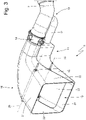
figure 3 is a perspective view of an end chamber (which is not manufactured according to the invention and is provided with two movable partitions) of an exhaust duct of the exhaust system offigure 1 ; -
figure 4 is a front view of the end chamber offigure 3 ; -
figure 5 is a longitudinal section view of a portion of the end chamber offigure 3 ; -
figures 6-9 are schematic views of the end chamber offigure 3 with the movable partitions in different positions; -
figures 10 ,11 and12 are schematic views of a different embodiment of the end chamber offigure 3 (which is manufactured according to the invention) with the movable partitions in different positions and highlighting the air flows flowing under the vehicle; and -
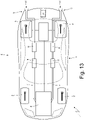
figure 13 is a schematic plan view of the car offigure 1 , in which the exhaust system is designed according to a different embodiment. - In
figure 1 , number 1 indicates, as a whole, a car provided with twofront wheels 2 and with tworear drive wheels 3, which receive the torque from aninternal combustion engine 4, which is supercharged by means of a turbocharger and is arranged in a front position. - The car 1 is provided with a
passenger compartment 5 which is designed to house the driver and possible passengers. - According to a possible, though non-binding embodiment, the
internal combustion engine 4 is a "V8" engine and has two (twin) banks with four cylinders arranged at an angle relative to one another so as to form a "V". In each bank, the four cylinders are connected to an intake manifold (not shown) by means of two intake valves and to an exhaust manifold (not shown) by means of two exhaust valves; each exhaust manifold collects the gases produced by the combustion, which cyclically flow out through the exhaust valves. - The
internal combustion engine 4 is provided with anexhaust system 6, which has the function of releasing the gases produced by the combustion into the atmosphere limiting both the noise and the content of polluting substances. Theexhaust system 6 comprises twotwin exhaust ducts 7, each originating from a corresponding exhaust manifold, so to receive the gases produced by the combustion from the exhaust manifold itself, and ending in the area of the tail of the car 1. Along eachexhaust duct 7 there are known exhaust gas treatment devices 8: there always are at least one catalytic converter and a particulate filter or a further catalytic element (in order to comply with EURO6D standards on polluting emissions). - Each exhaust duct 7 (which originates from the internal combustion engine 4) has an end chamber (part) 9, which ends with an outlet opening 10, through which the exhaust gases are released into the atmosphere.
- According to
figure 2 , the car 1 comprises a bottom wall delimiting a lower surface, which faces a road surface and, in use, is brushed by an air flow flowing under the car 1. - According to
figures 3 ,4 and5 , the exhaust system 6 (which is not manufactured according to the invention) comprises, for eachexhaust duct 7, asilencer device 11, which leads to the corresponding end chamber 9 (namely, which sends the exhaust gases flowing through it into the corresponding end chamber 9). Furthermore, theexhaust system 6 comprises, for eachexhaust duct 7, abypass duct 12, which originates from theexhaust duct 7 in the area of abifurcation 13 and ends in an inlet of thecorresponding silencer device 11; in other words, eachbypass duct 12 is an alternative to the last segment of acorresponding exhaust duct 7. - Finally, the
exhaust system 6 comprises, for eachexhaust duct 7, anadjustment valve 14, which can be electronically controlled, is arranged along theexhaust duct 7 downstream of thebifurcation 13 where thecorresponding bypass duct 12 originates (namely, is arranged between thebifurcation 13 and the end chamber 9) and is designed to adjust the exhaust gas flow towards theend chamber 9. Preferably, eachadjustment chamber 14 has an even partial opening possibility between a completely closed position and a completely open position; namely, eachadjustment valve 14 is not an ON/OFF valve, but can assume a range of intermediate positions between a completely closed position and a completely open position. - Each
silencer device 11 is a traditional silencer device and, for example, consists of atubular body 15, which is provided with an inlet opening 16 (where thecorresponding bypass duct 12 is fitted), with an outlet opening 17, which leads to theend chamber 9, and with an inner labyrinth (not shown), which determines a path for the exhaust gases from the inlet opening 16 to the outlet opening 17. - When each
adjustment valve 14 is open, the exhaust gases tend to directly flow into theend chamber 9, thus avoiding thebypass duct 12 and the silencer device 11 (because of the greater load losses experienced when flowing through the silencer device 11), whereas, when eachadjustment valve 14 is closed, the exhaust gases are forced to flow through thebypass duct 12 in order to reach theend chamber 9. In other words, theadjustment valves 14 are moved towards a completely closed position in order to prevent the exhaust gases from flowing in the last segment of theexhaust ducts 7, thus forcing the exhaust gases, in order for them to reach theend chambers 9, to flow through thebypass ducts 12, which end in thesilencer devices 11 and, as a consequence, damp noises to a greater extent and have a greater back pressure; vice versa, theadjustment valves 14 are moved to a completely open position in order to direct the exhaust gas flow towards the last segment of the exhaust ducts 7 (thebypass ducts 12 do not need to be closed as the greater back pressure determined by thesilencer devices 11 minimizes the exhaust gas flow along thebypass ducts 12 when an alternative, freer path is available). - Each
end chamber 9 comprises atubular body 18 and has an inlet opening 19, which is connected to theexhaust duct 7, and the outlet opening 10 opposite the inlet opening 19. The exhaust gases coming from theexhaust duct 7 flow into the end chamber 9 (namely, into the tubular body 18) through the inlet opening 19 and flow out of the end chamber 9 (namely, the tubular body 18) through the outlet opening 10. Each end chamber 9 (namely, each tubular body 18) is shaped like a trumpet increasing in size towards the outlet opening 10, has a cross section with a rectangular shape and is delimited by twofixed base walls 20 and 21 (a lower and an upper wall, respectively), which are opposite one another and diverge towards the outlet opening 10, and by twofixed side walls 22, which are opposite and parallel to one another. - The
end chamber 9 of eachexhaust duct 7 has twomovable partitions 23 opposite and facing one another, which can be moved to different positions (as evidently shown infigures 6-9 ). In eachend chamber 9 there is a motor-driven actuator device 24 (namely, provided with a preferably electric or pneumatic motor, which is designed to actively generate a movement), which is configured to move themovable partitions 23; preferably (though, not necessarily), eachactuator device 24 is configured to move the twomovable partitions 23 in an independent manner. In other words, each motor-drivenactuator device 24 is active and is electronically (electrically) controlled so as to generate a force (torque) that determines a movement of themovable partitions 23; as a consequence, in eachend chamber 9, the position of themovable partitions 23 is adjustable (by controlling the corresponding actuator device 24) completely independently of the pressure and the flow rate of the exhaust gases flowing through the end chamber 9 (for example, themovable partitions 23 can be moved so as to have a very large outlet opening 10, when the pressure and the flow rate of the exhaust gases are moderate, and can be moved so as to have a very small outlet opening 10, when the pressure and the flow rate of the exhaust gases are high). - According to a preferred embodiment, each
movable partition 23 is hinged so as to rotate around a rotation axis 25 (which is arranged horizontally); namely, eachmovable partition 23 is hinged to thetubular body 25 in the area of afixed base wall rotation axis 25. As a consequence, eachactuator device 24 is configured to rotate the twomovable partitions 23 around the respective rotation axes 25 (in this way, the movement of the twomovable partitions 23 can cause the twomovable partitions 23 to move away from one another or can cause the twomovable partitions 23 to move close to one another). - In the
end chamber 9 of eachexhaust duct 7, the twomovable partitions 23 can be moved between a maximum expansion position (shown, for example, infigure 6 ) and a minimum expansion position (shown, for example, infigure 9 ); obviously, when the twomovable partitions 23 are in the maximum expansion position (shown, for example, infigure 6 ), an area of theoutlet opening 10 is (significantly) larger than an area of the outlet opening 10 when the twomovable partitions 23 are in the minimum expansion position (shown, for example, infigure 9 ). - In the maximum expansion position (shown, for example, in
figure 5 ), or even in other expansion positions (shown, for example, infigure 7 ), the twomovable partitions 23 cause theend chamber 9 of theexhaust duct 7 to gain a diverging shape progressively increasing a cross section area as the outlet opening 10 gets closer. - According to a preferred embodiment, in the minimum expansion position (shown in
figure 9 ), the twomovable partitions 23 cause theend chamber 9 of theexhaust duct 7 to gain a converging shape progressively decreasing a cross section area as the outlet opening 10 gets closer. - Intermediate positions (shown, for example, in
figure 8 ) between the minimum expansion position (shown infigure 9 ) and the maximum expansion position (shown, for example, infigure 5 ) are also possible. - Namely, each
actuator device 24 is capable of placing and holding the twomovable partitions 23 in intermediate positions between the maximum expansion position (shown infigure 6 ) and the minimum expansion position (shown infigure 9 ) . - According to a possible embodiment shown in
figures 3 ,4 and5 , eachfixed base wall rotation axis 25 of the respective movable partition 23 (namely, eachfixed base wall movable partition 23 rests against thefixed base wall movable partitions 23 are completely inserted inside the end chamber 9 (namely, inside the tubular body 18) and, hence, when they rotate around the respective rotation axes 25, they slide against the fixedside walls 22. - According to a possible embodiment shown in
figures 3 ,4 and5 , eachsilencer device 11 is arranged under the respective end chamber 9 (namely, thetubular body 15 of eachsilencer device 11 is arranged under theend chamber 9, i.e. under the tubular body 18). As a consequence, thelower base wall 20 of each end chamber 9 (namely, of each tubular body 18) comprises at least oneinlet opening 26, through which thesilencer device 11 leads (namely, overlapping the outlet opening 17 of the silencer device 11). Preferably, in eachend chamber 9, theinlet opening 26 is arranged upstream of themovable partitions 23 relative to the exhaust gas flow. - In other words, each
end chamber 9 has theinlet opening 19 and theinlet opening 26, which are separate from and independent of one another, and theoutlet opening 10, through which exhaust gases are released into the atmosphere. Theexhaust duct 7 originates from theinternal combustion engine 4 and leads to the inlet opening 19 of theend chamber 9, whereas thesilencer device 11 has anoutlet opening 17, which directly leads to the inlet opening 26 of theend chamber 9. Thebypass duct 12 originates from theexhaust duct 7 in the area of thebifurcation 13 and ends in the inlet opening 16 of thesilencer device 11; furthermore, theadjustment valve 14 is arranged along theexhaust duct 7 downstream of the bifurcation 13 (namely, between thebifurcation 13 and the inlet opening 19) and is designed to adjust the exhaust gas flow towards the inlet opening 19 of theend chamber 9. - According to a preferred embodiment, each
silencer device 11 is connected to theend chamber 9 so as to form one single body with theend chamber 9; namely, thetubular body 15 of thesilencer device 11 is steadily and firmly connected (typically, by means of welding) to the end chamber 9 (namely, to the tubular body 18) and, hence, thetubular body 15 and thetubular body 18 could share the same fixedbase wall outlet opening 10; thesilencer device 11 has a shape that is complementary to the shape of the end chamber 9 (namely, of the tubular body 18) and, hence, decreases in size towards theoutlet opening 10. In this way, the single body consisting of thetubular body 15 of thesilencer device 11 and of the end chamber 9 (namely, the tubular body 18) has an approximately parallelepiped-shaped conformation. - There also is a control unit 27 (schematically shown in
figure 1 ), which is configured to change the position of themovable partitions 23 of each end chamber 9 (by controlling the corresponding actuator device 24) depending on: a rotation speed of theinternal combustion engine 4, an engine load of theinternal combustion engine 4, a gear engaged in a gearbox coupled to theinternal combustion engine 4, a longitudinal speed of a car 1 equipped with theinternal combustion engine 4, and a longitudinal acceleration of the car 1 equipped with theinternal combustion engine 4. - Namely, the
control unit 27 is configured to detect (for example, by reading them from the BUS network of the car): the rotation speed of theinternal combustion engine 4, the engine load of theinternal combustion engine 4, the gear engaged in the gearbox, the longitudinal speed of the car, and the longitudinal acceleration of the car 1; knowing this information (which is read beforehand), thecontrol unit 27 can establish the position of themovable partitions 23 of eachend chamber 9 depending on this information. - The
control unit 27 could be configured to change the position of themovable partitions 23 of eachend chamber 9 also depending on the driving mode selected by the driver (namely, it can be a sports driving mode, a racing driving mode, a city driving mode, a motorway driving mode, a wet-road driving mode..., which is generally selected by the driver by acting upon a selector called "hand lever"). - The
control unit 27 has to control the position of themovable partitions 23 of eachend chamber 9 so as to pursue three aims: complying with type approval regulations in terms of intensity of the sound emitted by the exhaust system (non-negotiable requirement that always has to be fulfilled), obtaining a high "quality" of the sound emitted by the exhaust system (namely, a type of sound emitted by the exhaust system that can be considered as pleasant by drivers and, hence, meet their expectations), and maximizing the performances of theinternal combustion engine 4. Provided that thecontrol unit 27 is configured to always comply with type approval regulations in terms of intensity of the sound emitted by the exhaust system, in some situations, thecontrol unit 27 can favour the "quality" of the sound emitted by the exhaust system rather than the performances of theinternal combustion engine 4, whereas, in other situations, thecontrol unit 27 can favour the performances of theinternal combustion engine 4 rather than the "quality" of the sound emitted by the exhaust system. - Generally speaking, the
control unit 27 is configured to hold themovable partitions 23 of eachend chamber 9 in a minimum expansion position in the presence of a small number of revolutions per minute and of small loads of theinternal combustion engine 4 and to move themovable partition 23 of eachend chamber 9 towards a maximum expansion position in the presence of a large number of revolutions per minute and of great loads of theinternal combustion engine 4. Furthermore, thecontrol unit 27 is configured to move themovable partitions 23 of eachend chamber 9 towards a minimum expansion position in low gears and to move themovable partitions 23 of eachend chamber 9 towards a maximum expansion position in high gears. - According to a preferred embodiment, in the
control unit 27 there are stored different maps (each corresponding to one or more driving modes), which provide, as an output, the desired (ideal) position of themovable partition 23 of eachend chamber 9 based on the data provided as an input on the number of revolutions per minute and on the engine load of theinternal combustion engine 4 as well as on the gear engaged in the gearbox coupled to theinternal combustion engine 4. Obviously, each map stored in thecontrol unit 27 comprises a limited number of points and, therefore, thecontrol unit 27 could carry out interpolations between the closest points of a map in order to determine the desired (ideal) position of themovable partitions 23 of eachend chamber 9. - In the maximum expansion position (shown, for example, in
figure 5 ), the "open" namely "diverging" position of themovable partitions 23 of eachend chamber 9 confers to theexhaust duct 7 the minimum exhaust back pressure and also confers to theexhaust duct 7 the minimum exhaust noise damping ability; on the other hand, in the minimum expansion position (shown, for example, infigure 9 ), the "closed" namely "converging" position of themovable partitions 23 of eachend chamber 9 confers to theexhaust duct 7 the maximum exhaust noise damping ability. - The
control unit 27 is configured to move themovable partitions 23 of eachend chamber 9 towards the minimum expansion position (shown, for example, infigure 9 ) when it is necessary (useful) to favour silencing rather than performances and to move themovable partitions 23 of eachend chamber 9 towards the maximum expansion position (shown, for example, infigure 5 ) when it is necessary (useful) to favour performances rather than silencing. - In the alternative embodiment shown in
figures 10 ,11 and12 (which is part of the invention), in eachexhaust duct 7, thesilencer device 11 is arranged above the end chamber 9 (on the opposite side relative to the fixed base wall 20) instead of under theend chamber 9; furthermore, the (lower) fixedbase wall 20 ends in the area of therotation axis 25 of the respective movable partition 23 (namely, ends in the area of an end of the respective movable partition 23) and, as a consequence, the lowermovable partition 23 delimits a lower surface of theend camber 9, which faces the road surface and, in use, is brushed by the air flow flowing under the car 1. - According to a preferred (though non-binding) embodiment, there also is a fixed
wall 28, which is connected to the end chamber 9 (namely, to the tubular body 18), covers theend chamber 9 at the bottom, lower than the (lower) fixedbase wall 20, ends in the area of therotation axis 25, delimits a lower surface of the end chamber 9 (namely, of the tubular body 18) facing the road surface and progressively increases a distance from the road surface towards theoutlet opening 10. - In this embodiment, the
control unit 27 is configured to change, by controlling theactuator device 24, the position of each lower movable partition 23 (namely, the one connected to the lower fixed base wall 20) also depending on the requested aerodynamic load and, hence, thecontrol unit 27 is configured to move each lowermovable partition 23 away from the road surface when a greater aerodynamic load is requested. - Indeed, by moving the lower
movable partition 23 away from the road surface, the width of the "extractor channel" defined between the road surface and the lowermovable partition 23 is increased, thus increasing the aerodynamic load generated by the "extractor channel". - In particular, at low and medium speeds (indicatively, below 150-180 km/h) the
control unit 27 establishes the position of thepartitions 23 of eachend chamber 9 only based on silencing needs, whereas at high speeds (indicatively, above 150-180 km/h) thecontrol unit 27 establishes the position of thepartitions 23 of eachend chamber 9 also and especially based on aerodynamic needs, favouring the generation of load at high speeds. - In the embodiment shown in the accompanying figures, the
end chamber 9 of eachexhaust duct 7 has twomovable partitions 23 facing and opposite one another; according to different embodiments which are not shown herein, theend chamber 9 of eachexhaust duct 7 has one singlemovable partition 23 or three or moremovable partitions 23. In other words, the two oppositemovable partitions 23 do not necessarily have to be present, there could be one singlemovable partition 23. - In the variant shown in
figure 13 , there are neither the bypass ducts 12 (and, hence, the relative silencer devices 11) nor theadjustment valves 14; as a consequence, the entire management of the sound damping strategies is completely assigned to the variable geometry of theend chambers 9 of theexhaust ducts 7. In this embodiment, the lowermovable partitions 23 preferably also have an aerodynamic function, since they delimit a lower surface of theend chamber 9, which faces the road surface and, in use, is brushed by the air flow flowing under the car 1. - According to a preferred embodiment, each
end chamber 9 is arranged behind a correspondingrear wheel 3 so as to leave a larger space between the tworear wheels 3 for an aerodynamic extractor. - In the embodiments shown in the accompanying figures, the
internal combustion engine 4 has eightcylinders 6 arranged in a V shape. Obviously, the internal combustion engine could have a different number of cylinders and/or a different arrangement of the cylinders; in case of internal combustion engines with inline cylinders (hence, with one single bank of cylinders), there usually is onesingle exhaust duct 7 and, therefore, oneend chamber 9. - In the embodiments shown in the accompanying figures, the
internal combustion engine 4 is supercharged; according to other embodiments which are not shown herein, theinternal combustion engine 4 is not supercharged, namely it is an aspirated engine. - The embodiments described herein can be combined with one another, without for this reason going beyond the scope of protection of the invention.
- The
exhaust system 6 described above has numerous advantages. - First of all, the
exhaust system 6 described above allows for an ideal silencing at low engine speeds and, at the same time, allows the exhaust back pressure to be minimized at high engine speeds. - In particular, the
exhaust system 6 described above, by properly adjusting both the width and/or the shape of each outlet opening 10 (namely, by properly adjusting the sound amplification/damping ability of each variable geometry end chamber 9) and the position of eachadjustment valves 14, allows for an optimization, in any possible operating condition, of the frequency response of each variablegeometry end chamber 9. - In the embodiment shown in
figures 11 ,12 and13 , theexhaust system 6 also has an aerodynamic effect that can be used when needed, namely when the speed of the car is high and, hence, aerodynamics is more important than silencing (namely, when the speed of the car exceeds 150-180 km/h). - The
exhaust system 6 described above is particularly light and compact, since thesilencer devices 11 have particularly small dimensions (for they operate together and in a combined manner with the respective variable geometry end parts 9); namely, the overall silencing effect is not generated by the sole silencingdevices 11, but is generated by the assembly consisting of the silencingdevices 11 and the variable geometry end parts 9 (hence, thesilencer devices 11 can be significantly smaller than usual). - Finally, the
exhaust system 6 described above is easy and economic to be manufactured, since, compared so a similartraditional exhaust system 6, it requires the addition of a few small-sized pieces which can easily be manufactured. -
- 1
- car
- 2
- front wheels
- 3
- rear wheels
- 4
- internal combustion engine
- 5
- passenger compartment
- 6
- exhaust system
- 7
- exhaust duct
- 8
- treatment devices
- 9
- end chamber
- 10
- outlet opening
- 11
- silencer device
- 12
- bypass duct
- 13
- bifurcation
- 14
- adjustment valve
- 15
- tubular body
- 16
- inlet opening
- 17
- outlet opening
- 18
- tubular body
- 19
- inlet opening
- 20
- base wall
- 21
- base wall
- 22
- side walls
- 23
- movable partitions
- 24
- actuator device
- 25
- rotation axis
- 26
- inlet opening
- 27
- control unit
- 28
- fixed wall
Claims (12)
- A car (1) comprising:two front wheels (2);two rear wheels (3);a bottom wall, which delimits a lower surface, which faces a road surface and, in use, is brushed by an air flow flowing under the car (1);an internal combustion engine (4); andan exhaust system (6), which is coupled to the internal combustion engine (4) and comprises an exhaust duct (7), which originates from the internal combustion engine (4) and has an end chamber (9), which ends with an outlet opening (10), through which exhaust gases are released into the atmosphere;wherein the end chamber (9) of the exhaust duct (7) has at least one movable partition (23), which can be moved to different positions so as to change the width of the outlet opening (10);the car (1) is characterized in that the movable partition (23) delimits a lower surface of the end chamber (9), which faces the road surface and, in use, is brushed by the air flow flowing under the car (1).
- The car (1) according to claim 1, wherein the end chamber (9) comprises a first fixed wall (28), which ends in the area of an end of the movable partition (23) and delimits a lower surface of the end chamber (9), which faces the road surface and, in use, is brushed by the air flow flowing under the car (1).
- The car (1) according to claim 2, wherein the first fixed wall (28) progressively increases a distance from the road surface towards the outlet opening (10).
- The car (1) according to claim 2 or 3, wherein the end chamber (9) comprises a second fixed wall (20), which ends in the area of an end of the movable partition (23), is arranged higher than the first fixed wall (28) and delimits, at the bottom, a space where exhaust gases flow.
- The car (1) according to one of the claims from 1 to 4 and comprising:a motor-driven actuator device (24), which is configured to actively move the movable partition (23) and can be electronically controlled; anda control unit (27), which is configured to change, by controlling the actuator device (24), the position of the movable partition (23).
- The car (1) according to claim 5, wherein the control unit (27) is configured to move the movable partition (23) away from the road surface, when a greater aerodynamic load is requested.
- The car (1) according to one of the claims from 1 to 6, wherein the end chamber (9) is arranged behind a corresponding rear wheel (3).
- The car (1) according to one of the claims from 1 to 7, wherein the exhaust system (6) comprises:a silencer device (11), which leads to the end part (9);a bypass duct (12), which originates from the exhaust duct (7) in the area of a bifurcation (13) and ends in an inlet of the silencer device (11); andan adjustment valve (14), which can be electronically controlled, is arranged along the exhaust duct (7) downstream of the bifurcation (13) where the bypass duct (12) originates and is designed to adjust the exhaust gas flow towards the end part (9).
- The car (1) according to claim 8, wherein the silencer device (11) is connected to the end chamber (9) so as to form one single body with the end chamber (9).
- The car (6) according to claim 8 or 9, wherein the silencer device (11) is arranged above the tubular body (18) on the opposite side relative to the movable partition (23).
- The car (1) according to one of the claims from 1 to 10, wherein the movable partition (23) can be moved between a maximum expansion position, in which the movable partition (23) causes the end chamber (9) of the exhaust duct (7) to gain a diverging shape progressively increasing a cross section area as the first outlet opening (10) gets closer, and a minimum expansion position, in which the movable partition (23) causes the end chamber (9) of the exhaust duct (7) to gain a converging shape progressively decreasing a cross section area as the first outlet opening (10) gets closer.
- The car (1) according to one of the claims from 1 to 11, wherein the end chamber (9) of the exhaust duct (7) has two opposite movable partitions (23), only one of them delimiting a lower surface of the end chamber (9), which faces the road surface and, in use, is brushed by the air flow flowing under the car (1).
Applications Claiming Priority (1)
| Application Number | Priority Date | Filing Date | Title |
|---|---|---|---|
| IT202000032849 | 2020-12-30 |
Publications (2)
| Publication Number | Publication Date |
|---|---|
| EP4023862A1 true EP4023862A1 (en) | 2022-07-06 |
| EP4023862B1 EP4023862B1 (en) | 2024-02-28 |
Family
ID=75111764
Family Applications (1)
| Application Number | Title | Priority Date | Filing Date |
|---|---|---|---|
| EP21218279.4A Active EP4023862B1 (en) | 2020-12-30 | 2021-12-30 | Car provided with an exhaust system with aerodynamic effect |
Country Status (3)
| Country | Link |
|---|---|
| US (1) | US11959406B2 (en) |
| EP (1) | EP4023862B1 (en) |
| JP (1) | JP2022104874A (en) |
Families Citing this family (2)
| Publication number | Priority date | Publication date | Assignee | Title |
|---|---|---|---|---|
| KR102768237B1 (en) * | 2020-07-14 | 2025-02-18 | 쩌지앙 길리 홀딩 그룹 씨오., 엘티디. | Exhaust noise devices, systems, vehicles and methods |
| EP4671511A1 (en) * | 2024-06-24 | 2025-12-31 | FERRARI S.p.A. | EXHAUST UNITS FOR ROAD VEHICLES |
Citations (6)
| Publication number | Priority date | Publication date | Assignee | Title |
|---|---|---|---|---|
| US1483354A (en) | 1919-11-25 | 1924-02-12 | Jr Frederick Kopper | Gas-engine muffler |
| GB2274681A (en) | 1993-01-29 | 1994-08-03 | Linde Ag | I.c.engine exhaust outlet flow control |
| US20080282688A1 (en) | 2007-05-18 | 2008-11-20 | International Truck Intellectual Property Company, Llc | Engine gas temperature reduction |
| KR20130061580A (en) * | 2011-12-01 | 2013-06-11 | 현대자동차주식회사 | Exhaust device for vehicle |
| DE102012112433A1 (en) * | 2012-12-17 | 2014-06-18 | Dr. Ing. H.C. F. Porsche Aktiengesellschaft | Exhaust system for an internal combustion engine |
| KR20160108625A (en) | 2015-03-04 | 2016-09-20 | 현대자동차주식회사 | Suppression apparatus of flow noise for exhaust gas |
Family Cites Families (7)
| Publication number | Priority date | Publication date | Assignee | Title |
|---|---|---|---|---|
| JPS6453415U (en) * | 1987-09-30 | 1989-04-03 | ||
| JP3952063B2 (en) * | 2005-04-13 | 2007-08-01 | トヨタ自動車株式会社 | Car body bottom surface air flow control device |
| US20070107981A1 (en) * | 2005-10-07 | 2007-05-17 | Sicotte Jason M | Exhaust silencer |
| KR100759765B1 (en) * | 2007-02-15 | 2007-09-20 | 박정석 | Exhaust gas control device of turbo vehicle |
| US9902439B2 (en) * | 2016-01-04 | 2018-02-27 | GM Global Technology Operations LLC | Control of airflow relative to a vehicle via active underbody panel(s) |
| DE102017206642B4 (en) * | 2017-04-20 | 2026-03-12 | Bayerische Motoren Werke Aktiengesellschaft | Method for operating an exhaust flap for an exhaust system of a motor vehicle |
| CN112228196B (en) * | 2020-09-16 | 2022-07-12 | 浙江吉利控股集团有限公司 | Vector tail pipe device and control system and vehicle thereof |
-
2021
- 2021-11-10 US US17/523,135 patent/US11959406B2/en active Active
- 2021-11-19 JP JP2021189019A patent/JP2022104874A/en active Pending
- 2021-12-30 EP EP21218279.4A patent/EP4023862B1/en active Active
Patent Citations (6)
| Publication number | Priority date | Publication date | Assignee | Title |
|---|---|---|---|---|
| US1483354A (en) | 1919-11-25 | 1924-02-12 | Jr Frederick Kopper | Gas-engine muffler |
| GB2274681A (en) | 1993-01-29 | 1994-08-03 | Linde Ag | I.c.engine exhaust outlet flow control |
| US20080282688A1 (en) | 2007-05-18 | 2008-11-20 | International Truck Intellectual Property Company, Llc | Engine gas temperature reduction |
| KR20130061580A (en) * | 2011-12-01 | 2013-06-11 | 현대자동차주식회사 | Exhaust device for vehicle |
| DE102012112433A1 (en) * | 2012-12-17 | 2014-06-18 | Dr. Ing. H.C. F. Porsche Aktiengesellschaft | Exhaust system for an internal combustion engine |
| KR20160108625A (en) | 2015-03-04 | 2016-09-20 | 현대자동차주식회사 | Suppression apparatus of flow noise for exhaust gas |
Also Published As
| Publication number | Publication date |
|---|---|
| CN114687844A (en) | 2022-07-01 |
| US11959406B2 (en) | 2024-04-16 |
| EP4023862B1 (en) | 2024-02-28 |
| US20220205377A1 (en) | 2022-06-30 |
| JP2022104874A (en) | 2022-07-12 |
Similar Documents
| Publication | Publication Date | Title |
|---|---|---|
| US8011186B2 (en) | Multi-stage turbocharger system | |
| US7913810B2 (en) | High-performance muffler assembly with multiple modes of operation | |
| EP3392479B1 (en) | Road vehicle with an internal combustion engine and provided with an exhaust noise transmission device | |
| US11131235B2 (en) | System and method for bypassing a turbocharger of a two stroke engine | |
| EP4023862B1 (en) | Car provided with an exhaust system with aerodynamic effect | |
| US9103274B2 (en) | Multi-stage turbocharger system | |
| JP2006097684A (en) | Multi-stage turbocharger using VTG turbine stage | |
| JPH01310116A (en) | Control device for engine | |
| CN107237675B (en) | Muffler apparatus including a centrally shared active control valve | |
| US11725573B2 (en) | Two-passage exhaust system for an engine | |
| EP4023863B1 (en) | Exhaust system for an internal combustion engine | |
| US11639684B2 (en) | Exhaust gas bypass valve control for a turbocharger for a two-stroke engine | |
| US20200182142A1 (en) | Wastegate Sizing For Turbocharger For A Two-Stroke Engine | |
| EP3892836B1 (en) | Exhaust system for an internal combustion engine | |
| US11174768B2 (en) | Exhaust system for an internal combustion engine | |
| US11236668B2 (en) | Method and system for controlling pressure in a tuned pipe of a two stroke engine | |
| CN114687844B (en) | Automobile provided with exhaust system with pneumatic effect | |
| US11174779B2 (en) | Turbocharger system for a two-stroke engine |
Legal Events
| Date | Code | Title | Description |
|---|---|---|---|
| PUAI | Public reference made under article 153(3) epc to a published international application that has entered the european phase |
Free format text: ORIGINAL CODE: 0009012 |
|
| STAA | Information on the status of an ep patent application or granted ep patent |
Free format text: STATUS: THE APPLICATION HAS BEEN PUBLISHED |
|
| AK | Designated contracting states |
Kind code of ref document: A1 Designated state(s): AL AT BE BG CH CY CZ DE DK EE ES FI FR GB GR HR HU IE IS IT LI LT LU LV MC MK MT NL NO PL PT RO RS SE SI SK SM TR |
|
| STAA | Information on the status of an ep patent application or granted ep patent |
Free format text: STATUS: REQUEST FOR EXAMINATION WAS MADE |
|
| 17P | Request for examination filed |
Effective date: 20230102 |
|
| P01 | Opt-out of the competence of the unified patent court (upc) registered |
Effective date: 20230525 |
|
| GRAP | Despatch of communication of intention to grant a patent |
Free format text: ORIGINAL CODE: EPIDOSNIGR1 |
|
| STAA | Information on the status of an ep patent application or granted ep patent |
Free format text: STATUS: GRANT OF PATENT IS INTENDED |
|
| INTG | Intention to grant announced |
Effective date: 20230927 |
|
| GRAS | Grant fee paid |
Free format text: ORIGINAL CODE: EPIDOSNIGR3 |
|
| GRAA | (expected) grant |
Free format text: ORIGINAL CODE: 0009210 |
|
| STAA | Information on the status of an ep patent application or granted ep patent |
Free format text: STATUS: THE PATENT HAS BEEN GRANTED |
|
| AK | Designated contracting states |
Kind code of ref document: B1 Designated state(s): AL AT BE BG CH CY CZ DE DK EE ES FI FR GB GR HR HU IE IS IT LI LT LU LV MC MK MT NL NO PL PT RO RS SE SI SK SM TR |
|
| REG | Reference to a national code |
Ref country code: GB Ref legal event code: FG4D |
|
| REG | Reference to a national code |
Ref country code: CH Ref legal event code: EP |
|
| REG | Reference to a national code |
Ref country code: DE Ref legal event code: R096 Ref document number: 602021009822 Country of ref document: DE |
|
| REG | Reference to a national code |
Ref country code: IE Ref legal event code: FG4D |
|
| REG | Reference to a national code |
Ref country code: LT Ref legal event code: MG9D |
|
| PG25 | Lapsed in a contracting state [announced via postgrant information from national office to epo] |
Ref country code: IS Free format text: LAPSE BECAUSE OF FAILURE TO SUBMIT A TRANSLATION OF THE DESCRIPTION OR TO PAY THE FEE WITHIN THE PRESCRIBED TIME-LIMIT Effective date: 20240628 |
|
| REG | Reference to a national code |
Ref country code: NL Ref legal event code: MP Effective date: 20240228 |
|
| PG25 | Lapsed in a contracting state [announced via postgrant information from national office to epo] |
Ref country code: LT Free format text: LAPSE BECAUSE OF FAILURE TO SUBMIT A TRANSLATION OF THE DESCRIPTION OR TO PAY THE FEE WITHIN THE PRESCRIBED TIME-LIMIT Effective date: 20240228 |
|
| PG25 | Lapsed in a contracting state [announced via postgrant information from national office to epo] |
Ref country code: GR Free format text: LAPSE BECAUSE OF FAILURE TO SUBMIT A TRANSLATION OF THE DESCRIPTION OR TO PAY THE FEE WITHIN THE PRESCRIBED TIME-LIMIT Effective date: 20240529 |
|
| PG25 | Lapsed in a contracting state [announced via postgrant information from national office to epo] |
Ref country code: HR Free format text: LAPSE BECAUSE OF FAILURE TO SUBMIT A TRANSLATION OF THE DESCRIPTION OR TO PAY THE FEE WITHIN THE PRESCRIBED TIME-LIMIT Effective date: 20240228 Ref country code: RS Free format text: LAPSE BECAUSE OF FAILURE TO SUBMIT A TRANSLATION OF THE DESCRIPTION OR TO PAY THE FEE WITHIN THE PRESCRIBED TIME-LIMIT Effective date: 20240528 Ref country code: NL Free format text: LAPSE BECAUSE OF FAILURE TO SUBMIT A TRANSLATION OF THE DESCRIPTION OR TO PAY THE FEE WITHIN THE PRESCRIBED TIME-LIMIT Effective date: 20240228 |
|
| PG25 | Lapsed in a contracting state [announced via postgrant information from national office to epo] |
Ref country code: ES Free format text: LAPSE BECAUSE OF FAILURE TO SUBMIT A TRANSLATION OF THE DESCRIPTION OR TO PAY THE FEE WITHIN THE PRESCRIBED TIME-LIMIT Effective date: 20240228 |
|
| PG25 | Lapsed in a contracting state [announced via postgrant information from national office to epo] |
Ref country code: RS Free format text: LAPSE BECAUSE OF FAILURE TO SUBMIT A TRANSLATION OF THE DESCRIPTION OR TO PAY THE FEE WITHIN THE PRESCRIBED TIME-LIMIT Effective date: 20240528 Ref country code: NO Free format text: LAPSE BECAUSE OF FAILURE TO SUBMIT A TRANSLATION OF THE DESCRIPTION OR TO PAY THE FEE WITHIN THE PRESCRIBED TIME-LIMIT Effective date: 20240528 Ref country code: NL Free format text: LAPSE BECAUSE OF FAILURE TO SUBMIT A TRANSLATION OF THE DESCRIPTION OR TO PAY THE FEE WITHIN THE PRESCRIBED TIME-LIMIT Effective date: 20240228 Ref country code: LT Free format text: LAPSE BECAUSE OF FAILURE TO SUBMIT A TRANSLATION OF THE DESCRIPTION OR TO PAY THE FEE WITHIN THE PRESCRIBED TIME-LIMIT Effective date: 20240228 Ref country code: IS Free format text: LAPSE BECAUSE OF FAILURE TO SUBMIT A TRANSLATION OF THE DESCRIPTION OR TO PAY THE FEE WITHIN THE PRESCRIBED TIME-LIMIT Effective date: 20240628 Ref country code: HR Free format text: LAPSE BECAUSE OF FAILURE TO SUBMIT A TRANSLATION OF THE DESCRIPTION OR TO PAY THE FEE WITHIN THE PRESCRIBED TIME-LIMIT Effective date: 20240228 Ref country code: GR Free format text: LAPSE BECAUSE OF FAILURE TO SUBMIT A TRANSLATION OF THE DESCRIPTION OR TO PAY THE FEE WITHIN THE PRESCRIBED TIME-LIMIT Effective date: 20240529 Ref country code: FI Free format text: LAPSE BECAUSE OF FAILURE TO SUBMIT A TRANSLATION OF THE DESCRIPTION OR TO PAY THE FEE WITHIN THE PRESCRIBED TIME-LIMIT Effective date: 20240228 Ref country code: ES Free format text: LAPSE BECAUSE OF FAILURE TO SUBMIT A TRANSLATION OF THE DESCRIPTION OR TO PAY THE FEE WITHIN THE PRESCRIBED TIME-LIMIT Effective date: 20240228 Ref country code: BG Free format text: LAPSE BECAUSE OF FAILURE TO SUBMIT A TRANSLATION OF THE DESCRIPTION OR TO PAY THE FEE WITHIN THE PRESCRIBED TIME-LIMIT Effective date: 20240228 |
|
| PG25 | Lapsed in a contracting state [announced via postgrant information from national office to epo] |
Ref country code: PL Free format text: LAPSE BECAUSE OF FAILURE TO SUBMIT A TRANSLATION OF THE DESCRIPTION OR TO PAY THE FEE WITHIN THE PRESCRIBED TIME-LIMIT Effective date: 20240228 Ref country code: PT Free format text: LAPSE BECAUSE OF FAILURE TO SUBMIT A TRANSLATION OF THE DESCRIPTION OR TO PAY THE FEE WITHIN THE PRESCRIBED TIME-LIMIT Effective date: 20240628 |
|
| REG | Reference to a national code |
Ref country code: AT Ref legal event code: MK05 Ref document number: 1661433 Country of ref document: AT Kind code of ref document: T Effective date: 20240228 |
|
| PG25 | Lapsed in a contracting state [announced via postgrant information from national office to epo] |
Ref country code: SE Free format text: LAPSE BECAUSE OF FAILURE TO SUBMIT A TRANSLATION OF THE DESCRIPTION OR TO PAY THE FEE WITHIN THE PRESCRIBED TIME-LIMIT Effective date: 20240228 Ref country code: PT Free format text: LAPSE BECAUSE OF FAILURE TO SUBMIT A TRANSLATION OF THE DESCRIPTION OR TO PAY THE FEE WITHIN THE PRESCRIBED TIME-LIMIT Effective date: 20240628 Ref country code: PL Free format text: LAPSE BECAUSE OF FAILURE TO SUBMIT A TRANSLATION OF THE DESCRIPTION OR TO PAY THE FEE WITHIN THE PRESCRIBED TIME-LIMIT Effective date: 20240228 Ref country code: LV Free format text: LAPSE BECAUSE OF FAILURE TO SUBMIT A TRANSLATION OF THE DESCRIPTION OR TO PAY THE FEE WITHIN THE PRESCRIBED TIME-LIMIT Effective date: 20240228 |
|
| PG25 | Lapsed in a contracting state [announced via postgrant information from national office to epo] |
Ref country code: DK Free format text: LAPSE BECAUSE OF FAILURE TO SUBMIT A TRANSLATION OF THE DESCRIPTION OR TO PAY THE FEE WITHIN THE PRESCRIBED TIME-LIMIT Effective date: 20240228 |
|
| PG25 | Lapsed in a contracting state [announced via postgrant information from national office to epo] |
Ref country code: SM Free format text: LAPSE BECAUSE OF FAILURE TO SUBMIT A TRANSLATION OF THE DESCRIPTION OR TO PAY THE FEE WITHIN THE PRESCRIBED TIME-LIMIT Effective date: 20240228 |
|
| PG25 | Lapsed in a contracting state [announced via postgrant information from national office to epo] |
Ref country code: EE Free format text: LAPSE BECAUSE OF FAILURE TO SUBMIT A TRANSLATION OF THE DESCRIPTION OR TO PAY THE FEE WITHIN THE PRESCRIBED TIME-LIMIT Effective date: 20240228 Ref country code: CZ Free format text: LAPSE BECAUSE OF FAILURE TO SUBMIT A TRANSLATION OF THE DESCRIPTION OR TO PAY THE FEE WITHIN THE PRESCRIBED TIME-LIMIT Effective date: 20240228 |
|
| PG25 | Lapsed in a contracting state [announced via postgrant information from national office to epo] |
Ref country code: AT Free format text: LAPSE BECAUSE OF FAILURE TO SUBMIT A TRANSLATION OF THE DESCRIPTION OR TO PAY THE FEE WITHIN THE PRESCRIBED TIME-LIMIT Effective date: 20240228 |
|
| PG25 | Lapsed in a contracting state [announced via postgrant information from national office to epo] |
Ref country code: SK Free format text: LAPSE BECAUSE OF FAILURE TO SUBMIT A TRANSLATION OF THE DESCRIPTION OR TO PAY THE FEE WITHIN THE PRESCRIBED TIME-LIMIT Effective date: 20240228 |
|
| PG25 | Lapsed in a contracting state [announced via postgrant information from national office to epo] |
Ref country code: SM Free format text: LAPSE BECAUSE OF FAILURE TO SUBMIT A TRANSLATION OF THE DESCRIPTION OR TO PAY THE FEE WITHIN THE PRESCRIBED TIME-LIMIT Effective date: 20240228 Ref country code: SK Free format text: LAPSE BECAUSE OF FAILURE TO SUBMIT A TRANSLATION OF THE DESCRIPTION OR TO PAY THE FEE WITHIN THE PRESCRIBED TIME-LIMIT Effective date: 20240228 Ref country code: RO Free format text: LAPSE BECAUSE OF FAILURE TO SUBMIT A TRANSLATION OF THE DESCRIPTION OR TO PAY THE FEE WITHIN THE PRESCRIBED TIME-LIMIT Effective date: 20240228 Ref country code: EE Free format text: LAPSE BECAUSE OF FAILURE TO SUBMIT A TRANSLATION OF THE DESCRIPTION OR TO PAY THE FEE WITHIN THE PRESCRIBED TIME-LIMIT Effective date: 20240228 Ref country code: DK Free format text: LAPSE BECAUSE OF FAILURE TO SUBMIT A TRANSLATION OF THE DESCRIPTION OR TO PAY THE FEE WITHIN THE PRESCRIBED TIME-LIMIT Effective date: 20240228 Ref country code: CZ Free format text: LAPSE BECAUSE OF FAILURE TO SUBMIT A TRANSLATION OF THE DESCRIPTION OR TO PAY THE FEE WITHIN THE PRESCRIBED TIME-LIMIT Effective date: 20240228 Ref country code: AT Free format text: LAPSE BECAUSE OF FAILURE TO SUBMIT A TRANSLATION OF THE DESCRIPTION OR TO PAY THE FEE WITHIN THE PRESCRIBED TIME-LIMIT Effective date: 20240228 |
|
| REG | Reference to a national code |
Ref country code: DE Ref legal event code: R097 Ref document number: 602021009822 Country of ref document: DE |
|
| PLBE | No opposition filed within time limit |
Free format text: ORIGINAL CODE: 0009261 |
|
| STAA | Information on the status of an ep patent application or granted ep patent |
Free format text: STATUS: NO OPPOSITION FILED WITHIN TIME LIMIT |
|
| 26N | No opposition filed |
Effective date: 20241129 |
|
| PG25 | Lapsed in a contracting state [announced via postgrant information from national office to epo] |
Ref country code: SI Free format text: LAPSE BECAUSE OF FAILURE TO SUBMIT A TRANSLATION OF THE DESCRIPTION OR TO PAY THE FEE WITHIN THE PRESCRIBED TIME-LIMIT Effective date: 20240228 |
|
| PG25 | Lapsed in a contracting state [announced via postgrant information from national office to epo] |
Ref country code: MC Free format text: LAPSE BECAUSE OF FAILURE TO SUBMIT A TRANSLATION OF THE DESCRIPTION OR TO PAY THE FEE WITHIN THE PRESCRIBED TIME-LIMIT Effective date: 20240228 |
|
| REG | Reference to a national code |
Ref country code: CH Ref legal event code: PL |
|
| PG25 | Lapsed in a contracting state [announced via postgrant information from national office to epo] |
Ref country code: LU Free format text: LAPSE BECAUSE OF NON-PAYMENT OF DUE FEES Effective date: 20241230 |
|
| REG | Reference to a national code |
Ref country code: BE Ref legal event code: MM Effective date: 20241231 |
|
| PG25 | Lapsed in a contracting state [announced via postgrant information from national office to epo] |
Ref country code: BE Free format text: LAPSE BECAUSE OF NON-PAYMENT OF DUE FEES Effective date: 20241231 |
|
| PG25 | Lapsed in a contracting state [announced via postgrant information from national office to epo] |
Ref country code: CH Free format text: LAPSE BECAUSE OF NON-PAYMENT OF DUE FEES Effective date: 20241231 |
|
| PG25 | Lapsed in a contracting state [announced via postgrant information from national office to epo] |
Ref country code: IE Free format text: LAPSE BECAUSE OF NON-PAYMENT OF DUE FEES Effective date: 20241230 |
|
| PGFP | Annual fee paid to national office [announced via postgrant information from national office to epo] |
Ref country code: GB Payment date: 20251223 Year of fee payment: 5 |
|
| PGFP | Annual fee paid to national office [announced via postgrant information from national office to epo] |
Ref country code: IT Payment date: 20251118 Year of fee payment: 5 |
|
| PGFP | Annual fee paid to national office [announced via postgrant information from national office to epo] |
Ref country code: FR Payment date: 20251223 Year of fee payment: 5 |
|
| PGFP | Annual fee paid to national office [announced via postgrant information from national office to epo] |
Ref country code: DE Payment date: 20251229 Year of fee payment: 5 |