EP4023835A1 - A roof window system with a cover assembly - Google Patents
A roof window system with a cover assembly Download PDFInfo
- Publication number
- EP4023835A1 EP4023835A1 EP21216882.7A EP21216882A EP4023835A1 EP 4023835 A1 EP4023835 A1 EP 4023835A1 EP 21216882 A EP21216882 A EP 21216882A EP 4023835 A1 EP4023835 A1 EP 4023835A1
- Authority
- EP
- European Patent Office
- Prior art keywords
- window system
- roof
- roof window
- cover plate
- mounting element
- Prior art date
- Legal status (The legal status is an assumption and is not a legal conclusion. Google has not performed a legal analysis and makes no representation as to the accuracy of the status listed.)
- Granted
Links
Images







Classifications
-
- E—FIXED CONSTRUCTIONS
- E04—BUILDING
- E04D—ROOF COVERINGS; SKY-LIGHTS; GUTTERS; ROOF-WORKING TOOLS
- E04D13/00—Special arrangements or devices in connection with roof coverings; Protection against birds; Roof drainage ; Sky-lights
- E04D13/03—Sky-lights; Domes; Ventilating sky-lights
- E04D13/0305—Supports or connecting means for sky-lights of flat or domed shape
- E04D13/031—Supports or connecting means for sky-lights of flat or domed shape characterised by a frame for connection to an inclined roof
-
- E—FIXED CONSTRUCTIONS
- E04—BUILDING
- E04B—GENERAL BUILDING CONSTRUCTIONS; WALLS, e.g. PARTITIONS; ROOFS; FLOORS; CEILINGS; INSULATION OR OTHER PROTECTION OF BUILDINGS
- E04B7/00—Roofs; Roof construction with regard to insulation
- E04B7/18—Special structures in or on roofs, e.g. dormer windows
-
- E—FIXED CONSTRUCTIONS
- E04—BUILDING
- E04D—ROOF COVERINGS; SKY-LIGHTS; GUTTERS; ROOF-WORKING TOOLS
- E04D13/00—Special arrangements or devices in connection with roof coverings; Protection against birds; Roof drainage ; Sky-lights
- E04D13/14—Junctions of roof sheathings to chimneys or other parts extending above the roof
- E04D13/147—Junctions of roof sheathings to chimneys or other parts extending above the roof specially adapted for inclined roofs
- E04D13/1473—Junctions of roof sheathings to chimneys or other parts extending above the roof specially adapted for inclined roofs specially adapted to the cross-section of the parts extending above the roof
- E04D13/1475—Junctions of roof sheathings to chimneys or other parts extending above the roof specially adapted for inclined roofs specially adapted to the cross-section of the parts extending above the roof wherein the parts extending above the roof have a generally rectangular cross-section
Definitions
- the present invention relates to a roof window system comprising at least two window units configured to be built in side by side, separated by a pre-defined spacing, in a roof structure of a roof, in particular comprising an inclined roof surface, each window unit comprising a top member, two side members, and a bottom member, said roof window system furthermore comprising a cover assembly spanning the spacing between facing side members of neighbouring window units in the mounted condition of the roof window system.
- Roof windows to be installed in inclined roof surfaces come in a variety of types, and are either installed as stand-alone window units, in which all sides of the roof window borders on the roofing, or in configurations in which several window units are built together to combine into larger arrays providing a larger light influx into a room of a building, and in which only outer sides of the outermost window units border on the surrounding roofing.
- Typical configurations of twin or quadruple roof window arrangements installed side-by-side and/or above each other, respectively, are shown and described in Applicant's European patent No. EP 1 581 706 B1 .
- the window units are typically standard roof windows in which the right side frame member of the left-hand window unit is located adjacent to the left side frame member of the right-hand window unit.
- cover assembly comprises a set of receiver brackets configured to be connected to the facing side members of neighbouring window units and a cover plate configured to be brought into releasable engagement with the set of receiver brackets.
- each receiver bracket is adapted to be installed in a groove in the facing side members of neighbouring window units. This facilitates the installation process even further, since the location of the receiver bracket or brackets is thereby given.
- each receiver bracket comprises at least one leg configured to be received in said groove, the leg being preferably provided with one or more holes to receive fastening means.
- the presence of the legs furthermore adds to the ease of installation.
- the cover plate preferably comprises a first mounting element and the receiver bracket comprises a complementary second mounting element, such that the first mounting element and the second mounting element are configured to be brought into contact with one another.
- the first mounting element and the second mounting element comprise such complementary shapes that movement of the cover plate relative to the receiver bracket or receiver brackets in a mounting direction is possible while movement in the opposite direction is at least temporarily prevented by a first engagement portion on the first mounting element brought into engagement with a second engagement portion on the second mounting element, preferably by a snap or clip engagement. This provides for a simple, yet reliable connection.
- the roof window system furthermore comprises a demount tool to provide disengagement of the cover plate from the receiver bracket(s).
- a demount tool to provide disengagement of the cover plate from the receiver bracket(s).
- the roof window system 1 comprises two window units 11, 12 configured side-by-side.
- a window unit can consist of a single window including frame, sash and pane etc. and/or comprise of more than one single window. It could be two windows placed over and under each other as seen in an inclination of the roof or positioned arbitrarily in extension of each other in the roof surface, and preferably having a common width and thus individual height. Each such window in an over and under configuration could also have unique features relating to the frame, sash and pane etc. It could be a fixed frame with a pane, a frame with a sash being fixed or able to turn around a centre, top, bottom or side axis. Alternatively or additionally, the frame could hold a ventilation device, solar panel etc. Also such a window unit could be of different size, e.g. width, compared with another unit to be placed in the side by side configuration.
- Each window unit 11, 12 here comprises an openable roof window of a well-known configuration, including a sash hinged in a frame representing the respective window unit by a top member 111, 121, two side members 112, 113, 122, 123, and a bottom member 114, 124.
- a combined width W of the roof window system 1 is the combination of the width of first window unit W1, the dimension of a spacing SP between the two window units 11, 12, and the width of second window unit W2.
- the common height H of the roof window system 1 is the height of any of window units 11, 12. It is noted that the individual widths of the first and second window units need not be identical; however, the height is a common height H.
- the roof structure 2 comprises rafters 20, 21 and battens 22.
- an upper horizontal trimmer 23, a lower horizontal trimmer 24 and a vertical trimmer 25 are installed.
- auxiliary batten pieces 28 are installed opposite the intended position of an upper support beam 31 and a lower support beam 32, respectively, which form part of the support assembly 3 to be described in further detail below.
- Fig. 2 is a perspective view of the roof structure 2 and of a support assembly 3 of the roof window system 1 as seen from the interior.
- the roof structure 2 furthermore comprises an underroofing 26 placed over the rafters 20, 21 and below the battens 22.
- the support assembly 3 is shown as from the interior of a building and comprises a set of support beams, here an upper support beam 31 and a lower support beam 32, configured to be mounted substantially horizontally in said roof structure 2 such that the top member 111, 121 and the bottom member 114, 124 of each window unit 11, 12 are intended to be connected with the respective support beam 31, 32 in a mounted condition of the roof window system 1, for instance by using window installation brackets connected to the frame and battens, respectively.
- Fig. 3 is a sectional view and shows in more detail the upper support beam 31 and lower support beam 32 in relation to the window unit 11.
- a lining panel 95 which at one edge is received in a groove 17 in the top member 111 of the first window unit 11. It is noted that such groove 17 is circumferential and present in all members of the frame of the roof windows constituting the window units. It is also shown that the lining panel 95 is allowed to form a bend between a first portion near the window unit 11 and a second inclined portion such that a diverging clearing is formed. By the bend, sufficient insulation is present in the area near the lining panel 95.
- the upper and lower parts of the insulating assembly 5 can be seen placed between the top frame member 111 and the upper support beam 31 and the bottom frame member 114 and the lower support beam 32. Also it is shown how the underroofing 26 is arranged with respect to the upper and lower support beams 31, 32 and how a supplementary underroof collar 96 is arranged over the battens 22 and connected to the top frame member 111 and how its arranged under the lower batten 22 below the window unit 11 and connected to the bottom frame member 114 of the window unit 11.
- the underroof collar 96 is brought into overlap with the underroofing 26.
- a vapour barrier membrane 27 forms part of the roof structure 2 such that the insulation is protected from moisture from the interior.
- a supplementary vapour barrier collar 97 is also provided, which at one edge portion is connected to the window units 11, 12 and at an opposite edge portion to the vapour barrier membrane 26. Also visible in Fig. 3 are two installation battens 29, of which the uppermost installation batten 29 is positioned to extend between the upper support beam 31 and the upper horizontal trimmer 23, and the lowermost installation batten 29 between the lower support beam 32 and the lower horizontal trimmer 24.
- a flashing arrangement 91 at the top and a flashing arrangement 94 at the bottom which provide a weather-tight transition between the window units 11, 12 and the surrounding roofing together with further flashing arrangements 92 and 93 indicated in Figs 4 and 5 .
- Fig. 6 and Fig. 7 are respectively an end perspective view of one of the support beams, here upper support beam 31, at its connection to the rafter 21.
- the support beam 31 has a top surface 311, a side surface 312, a side surface 313, and a bottom surface 314.
- the support beam 31 is inserted in a mounting bracket 4 comprising a base 41, an upstanding flange 43 on either side of the base 41, and two legs 42 each connected to a flange 43.
- the mounting bracket 4 is in turn fastened to the rafter 21 by suitable fastening means.
- the material of the support beams may in principle be chosen arbitrarily, as long as the material has sufficient strength and wear properties.
- a wooden material is chosen, and may include laminated wooden beams such as Glulam beams, Kerto ® beams etc. which are dimensionally stable, strong and light-weight.
- the base 41 comprises a first edge 411 and a second edge 412.
- Each upstanding flange 43 is connected to, in the embodiment shown perpendicularly to, the base 41 at a first transition edge 431 of the upstanding flange 43 and each leg 42 is connected to the respective upstanding flange 43 at a second transition edge 432 of the upstanding flange 43.
- the first transition edge 431 is perpendicular to the second transition edge 432.
- Each leg 42 comprises an inner free side edge portion 422 in extension of the second transition edge 432 of the upstanding flange 43 such that an upper section of each said leg 42 extends above a plane of the base 41 and a lower section of each said leg 42 extends below the plane of the base 41.
- the legs 42 have a relatively large extension in the height direction, perpendicular to the longitudinal direction of the rafter 21. In this way, it is possible to fasten the mounting brackets 4 at such a position that a minimum of fastening elements such as screws or nails are located close to the top of the rafter.
- the zone surrounding the window units 11, 12 in the roof structure 2 is rendered free of fastening elements which is advantageous for a number of reasons, including the overall mounting as well as insulation and other climate adaptability properties.
- each leg 42 and each upstanding flange 43 comprises at least one hole or aperture adapted to receive fastening means such as screws or nails.
- each leg 42 is provided with a plurality of holes and apertures 426, 427, 428 such that at least one hole or aperture is located in the upper section and at least one hole or aperture in the lower section. This provides for flexibility in the selection of holes for fastening of the mounting bracket 4 to the rafter 21.
- a hole 413 in the base 41 is intended to receive fastening means such as a screw driven into the support beam 31 or 32 once it has been introduced between the upstanding flanges 43.
- the upstanding flanges 43 are also provided with a set of holes 436 serving also to receive screws to be driven into the support beam 31 and 32.
- each mounting bracket 4 is connected to a rafter 21 or a vertical trimmer 25 by legs 42 such that the base 41 protrudes from the rafter 21 or vertical trimmer 25 and supports a bottom surface 314 of the respective support beam 31, 32.
- all mounting brackets 4 are connected to rafters; in case there are trimmers on either side, all mounting brackets are connected thereto.
- the connection advantageously takes place perpendicularly as shown.
- each upstanding flange 43 protrudes from the rafter 21 or vertical trimmer 25 as the case may be. Thereby, it supports a side surface 312, 313 of the respective support beam 31, 32, as shown perpendicularly.
- each support beam 31, 32 is in the configuration shown substantially flush with an upper side of the battens 22 of the roof structure 2 in the mounted condition of the roof window system 1. As mentioned in the above, this positioning is made possible by the particular configuration of the mounting brackets 4, in particular of the legs 42.
- the aperture in the roof structure 2 is preferably provided with insulation and the window units 11 and 12 are prepared for installation.
- stabilizing rails 6, 6b of a stabilizing assembly is connected to the respective window unit 11, 12 and window installation brackets 15 are connected to the window units in a manner known per se.
- Fig. 11 an insulating assembly 5 is shown connected to the roof structure 2.
- Figs 4 , 10 , 11 and 12 For the description of the stabilizing assembly and the insulating assembly of the roof window system according to the invention, reference is first made jointly to Figs 4 , 10 , 11 and 12 , in which a roof window system comprising two window units 11 and 12 configured to be mounted with a gap G of the spacing SP of about 100 mm is shown. Secondly, reference is made jointly to Figs 5 , 13 and 14 in which a roof window system comprising two window units 11 and 12 configured to be mounted with a gap G of the spacing SP of about 18 mm is shown. Details of the respective stabilizing assembly and insulating assembly will be described in the following.
- Fig. 15 shows an exploded isometric view of the insulating assembly 5 of the roof window system 1.
- the insulating assembly 5 comprises two side members 52, 53, a plurality of top and bottom members including at least a first and a second top member 511, 512, a first and a second bottom member 541, 542, and two transition members 55, 56, which together form a single insulating frame 50.
- Each side member 52, 53 has a length corresponding substantially to the common height H of the window units 11, 12, and each member 511, 512, 541, 542 of the top and bottom members has a length corresponding substantially to the respective width W1, W2 of the window units 11, 12.
- Each transition member 55, 56 is configured to be positioned between facing ends 5115, 5125 of the first and second top members 511, 512, and the at least first and second bottom members 541, 542, respectively.
- the two side members 52, 53, the top and bottom members 511, 512, 541, 542, and the two transition members 55, 56 extend along a periphery of the window units 11, 12 including the top members, the outer side members 112, 123 of the window units 11, 12 and span the combined width W and the common height H and depth D of the roof window system.
- each member of the plurality of top and bottom members 511, 512, 541, 542 is formed as a standard insulating frame piece comprising an insulating element 5121 and a supporting rail 5122 having a uniform cross-section.
- standard insulating frame piece encompasses components of commercially available insulating frames fitting a counterpart roof window of a pre-defined size, for instance within a size range of products.
- the configuration of an insulating frame piece is well-known per se, for instance from Applicant's EP 2 677 092 B1 .
- the insulating assembly 5 furthermore comprises a set of four connector brackets 57 configured to connect the side members 52, 53 to a respective top and bottom member 511, 541, 512, 542.
- the supporting rail 5122 of the standard insulating frame piece constituting each member of said plurality of top and bottom members 511, 512, 541, 542 has engagement means, preferably in the form of an opening, configured to engage with corresponding engagement means of the connector bracket 57, preferably comprising a barb or lug.
- each transition member 55, 56 comprises an insulating element 551 and an engagement element 552 configured to bring the transition member 55, 56 into engagement with the associated top and bottom members 511, 512, 541, 542 at the respective facing ends 5115, 5125 thereof.
- the insulating element 551 comprises an enlarged lower section 5511 and an upper section 5512, the enlarged lower section 5511 being provided with an inclined edge 5513 such that a ledge 5514 is formed in the transition area between the upper and lower sections 5512, 5511.
- the ledge 5514 may in principle have any suitable configuration but preferably surrounds at least in part the upper section 5512 on an inner face and end faces as shown.
- the engagement element 552 comprises an L-shaped clip with a first leg 5521 and a second leg 5522, the first leg 5521 being configured to be received in receiving means of the insulating element 551, which may take the form of a slot 5515 in an outer side of the upper section 5512 of the insulating element 551.
- the second leg 5522 of the L-shaped clip comprises engagement means configured to engage with corresponding engagement means of the member of said plurality of top and bottom members 511, 512, 541, 542.
- the engagement means here comprises a barb or lug 5523.
- the shape of the transition member 55, 56 is adapted to the shape of the member of said plurality of top and bottom members 511, 512, 541, 542.
- a width wb, wk and a depth db, dk of the transition member 55, 56 is chosen. Comparing Figs 18 and 19 , two different sizes are shown.
- the transition members could be chosen to span the spacing between facing sides of neighbouring roof windows placed at an arbitrary distance from each other. Typically, some standard distances are foreseen, but in principle, the insulating assembly could be provided for spacings ranging from almost contact within the neighbouring roof windows to 500 mm within the neighbouring roof windows. In the embodiments shown, two standardized widths of 100 mm and 18 mm are described
- the insulating element 551 of each transition member 55, 56 is advantageously made from a dimensionally stable material having good thermal insulating properties, preferably a polymer foam, such as extruded polyethylene (PE), polypropylene (PP), polyurethane (PU), polyvinylchloride (PVC), expanded polystyrene (EPS), extruded polystyrene (XPS) or mineral wool.
- a polymer foam such as extruded polyethylene (PE), polypropylene (PP), polyurethane (PU), polyvinylchloride (PVC), expanded polystyrene (EPS), extruded polystyrene (XPS) or mineral wool.
- the insulating assembly 5 is configured to cooperate with the stabilizing rail 6 positioned in the spacing SP between neighbouring window units 11, 12 in the mounted condition of the roof window system such that the stabilizing rails 6 and 6b are - at least in part - in abutment with the two transition members 55, 56.
- the insulating assembly 5 is supplied as an unassembled kit, in which the two side members 52, 53 and the plurality of top and bottom members 511, 512, 541, 542 are packaged together, preferably in parallel with each other, and each of the two transition members 55, 56 is connected to a respective one of the at least first and second top members 511, 512 and the at least first and second bottom members 541, 542.
- the transition members 55, 56 could be provided separately.
- transition members 55, 56 are shown as separate members, they could optionally be integrally connected to the top and/or bottom members either in a configuration where the transition member 55, 56 is partly integrated into one of the first and second top/bottom members 511, 512, 541, 542 or in a configuration where the transition member 55, 56 is fully integrated into both of the first and second top/bottom members 511, 512, 541, 542 thus forming a continuous top/bottom member.
- a first embodiment of the stabilizing rail 6 is shown. It is noted that a substantially identical, mirror-imaged second stabilizing rail 6b is provided as well. Where appropriate, reference will also be made to a second embodiment of the stabilizing rail 1006 of Fig. 22 and a third embodiment of the stabilizing rail 2006 of Fig. 23 , and to the interaction between respective insulating profiles of the stabilizing rails 6, 6b; 1006 of the stabilizing assembly and the transition member 55 of the insulation assembly 6 shown in Figs 24 and 25 , respectively. Only differences between the embodiments will be described in detail.
- each stabilizing rail 6, 6b; 1006, 1006b; 2006, 2006b has a generally longitudinal extension and comprises at least a strengthening profile 62, 62b; 1062, 1062b; 2062, 2062b.
- One or both stabilizing rails of a set comprises an insulating profile 61 fastened to the strengthening profile 62.
- the strengthening profile 62 comprises means for connection to the side member 113 of one window unit 11 of neighbouring window units 11, 12.
- the strengthening profile 62b of the second stabilizing rail 6b comprises means for connection to the side member 122 of the other window unit 12 of the roof window system.
- the insulating profile 61 has such a thickness tk, tb and depth dk, db that it substantially spans half of the gap G of the spacing SP between facing side members 113, 122 of neighbouring window units 11, 12 in the mounted condition of the roof window system 1. In this way, the insulating profiles 61 and 61b together span the gap G of the spacing SP.
- the strengthening profile 62 comprises a connection flange 621 with connection means 623, 624, 625, 626 for the connection of the stabilizing rail 6; 1006; 2006 to the window unit 11.
- the connection means comprise a set of lugs 623 protruding from a surface of the connection flange 621 configured to face and match holes in the side member 113 of the window unit 11 to which the stabilizing rail 6; 1006; 2006 is connected.
- connection means comprise at least one set of holes 624, 625 and/or set of apertures 626 for receiving fastening means and/or fittings, the position and number of the at least one set of holes or apertures 624, 625, 626 preferably depending on the common height H of the roof window system 1 and also matching holes provided in the side member 113 of the window unit 11. Matching the connection means of the stabilizing rail 6; 1006; 2006 with holes in the side members of the window units facilitates correct positioning and mounting.
- fastening means is screws 627 indicated in Figs 10 and 13 .
- the number and position of the fastening means may be chosen in accordance with the height of the window units 11, 12, and thus of the roof window system 1, such that three sets of two screws 627 are provided to fasten the stabilizing rail 6 to the side member 113 of the first window unit 11 and the stabilizing rail 6b to the side member 122 of the second window unit 12, namely one set near the top, one set near the bottom and one set substantially centrally.
- the common height H is larger, more than three sets may be provided, and fewer than three sets of screws 627 may be provided, for instance as shown in Fig. 13 .
- Each stabilizing rail 6, 6b; 1006, 1006b; 2006, 2006b has a length which is chosen in accordance with other dimensions of the roof window system 1, typically as substantially corresponding to the common height H of the roof window system 1.
- At least the insulating profile 61 is chosen to have a length corresponding to the full length of the stabilizing rail 6 but the strengthening profile 62 has a length which is shorter than the full length of the stabilizing rail 6, such as to leave an end portion at each end of the stabilizing rail 6 in which the insulating profile 61 protrudes beyond opposing ends of the strengthening profile 62, the length of said end portions being preferably about 10 to 60 mm, more preferably about 40 mm.
- ledge 5514 of the transition member 55 cooperates with the shoulder 613 and cut-out portion 614 of the insulating profile 61 at the top of the roof window system, and also at the inclined edge 5513 with the facing edge 5115 of the first top member 511 of the insulating assembly 5 (and correspondingly at the other side of the other stabilizing rail 6b).
- the insulating profile 1061 of the first stabilizing rail 1006 is shown in interaction with the transition member 56.
- the thickness tb of the insulating profile 61 which spans substantially the gap G of the spacing SP between neighbouring window units 11, 12 corresponds in substance to the width wb as defined by the upper section 5512 of the transition member 56.
- This second stabilizing rail 1006b comprises only strengthening profile 1062b, which is mounted reversely on the window unit 12 as compared with the strengthening profile 1062 mounted on the window unit 11.
- the strengthening profile 62 of the stabilizing rail 6; 1006 comprises a fastening flange 622 extending substantially perpendicularly to the connection flange 621, thus forming an L-shape, the fastening flange 622 being fastened to the insulating profile 61 at an under side, facing away from the connection flange 621, preferably by means of adhesion.
- the insulating profile 61 of the stabilizing rail 6; 1006; 2006 comprises a base section 611 defining said pre-defined thickness tk, tb.
- the insulating profile 61 of the stabilizing rail 6 comprises a ledge 612 and a shoulder portion 613 above the base section 611, and wherein the fastening flange 622 is positioned on the ledge 612 such that an upper side of the fastening flange 622 is substantially flush with an upper side of the shoulder portion 613.
- the insulating profile 2061 of the stabilizing rail 2006 comprises a base section 2611 defining said pre-defined thickness tb and an upper section 2615 having a smaller thickness
- the connection flange 2621 of the strengthening profile 2062 comprises a folded flange portion 2627, the connection flange 2621 and the folded flange portion 2627 form fastening surfaces relative to the upper section 2615 of the insulating profile 2061.
- the insulating profile 61 of the stabilizing rail 6 is made from a dimensionally stable material having good thermal insulating properties, preferably a polymer foam, such as extruded polyethylene (PE), polypropylene (PP), polyurethane (PU), polyvinylchloride (PVC), expanded polystyrene (EPS), extruded polystyrene (XPS) or mineral wool.
- a polymer foam such as extruded polyethylene (PE), polypropylene (PP), polyurethane (PU), polyvinylchloride (PVC), expanded polystyrene (EPS), extruded polystyrene (XPS) or mineral wool.
- PE polyethylene
- PP polypropylene
- PU polyurethane
- PVC polyvinylchloride
- EPS expanded polystyrene
- XPS extruded polystyrene
- the strengthening profile 62 is made from any suitable material which is capable of performing the function of a reinforcing rail, e.g. with properties like a gusset.
- a composite or metal material such as steel.
- a first embodiment of a cover assembly is shown, in a disengaged and an engaged position, respectively.
- the cover assembly is intended to cover the spacing between facing sides of neighbouring roof windows placed at an arbitrary distance from each other. Typically, some standard distances are foreseen, but in principle, the cover assembly could be provided for spacings ranging from a contact within the neighbouring roof windows to 500 mm within the neighbouring roof windows. In the embodiment shown, a standardized width of the gap G of the spacing SP of 100 mm is described. The person skilled in the art would be aware of necessary adaptions to the cover assembly to accommodate other dimensions.
- the cover assembly comprises a set of receiver brackets 7 configured to be connected to the facing side members 113, 122 of neighbouring window units 11, 12 and a cover plate 8 configured to be brought into releasable engagement with the set of receiver brackets 7.
- a prior art cover arrangement of a commercially available product traded under the name VELUX ® Dormer is shown in Fig. 28a and Fig. 28b .
- the set of receiver brackets 7 here includes four items. The number may be chosen in dependence of the height of the window units and hence of the roof window system; however, four receiver brackets have been found appropriate for most sizes window units.
- each receiver bracket 7 is adapted to be installed in a groove 17 in adjacent frame members 113, 122 of neighbouring window units 11, 12.
- This groove 17 is as mentioned in the above circumferential and typically provided in the frame of most roof windows.
- the groove 17 of the adjacent frame members serves to receive the receiver brackets 7.
- Each receiver bracket 7 comprises a base portion 70 from which a set of two second mounting elements 71 protrude to form rounded shapes, a second engagement portion 72 being here formed near an end of the respective second mounting element 71.
- each receiver bracket 7 comprises a leg 73 at an end of the second engagement portion 72 opposite the base portion 70.
- each leg 73 is received in the groove 17 of the respective frame member 113, 122.
- one or more holes 74 are provided in each leg 73 as shown in Fig. 30 in which two holes 74 are provided and configured to receive fastening means such as screws (not shown).
- the cover plate 8 comprises a base portion 80 from which a set of two first mounting elements 81 protrude, a first engagement portion 82 being preferably formed near a free end of the respective first mounting element 81.
- the cover plate 8 comprises an additional leg 83, preferably provided with a hook 84. Referring to Fig. 27 showing the engaged position, it is seen that the hook 84 is placed close to the frame members such that the entry to the groove 17 is also covered. It is furthermore seen that a side edge 801 of the base portion is located beyond the position of the respective first mounting element 81. In this way, the cover element 8 overlaps not only the entire spacing SP but also the portion of the side members 113, 122 in which the groove 17 is located.
- the circumferential groove 17 also receives the vapour barrier collar 97.
- the exact configuration of the vapour barrier collar 97 could in principle be chosen in any suitable way but it is preferred that that not only the top, bottom and outermost side members of the window units are provided with portions of the vapour barrier collar 97, but also the spacing SP between facing side members of the two neighbouring window units 11 and 12 as indicated in Fig. 26 .
- the vapour barrier collar 97 is here formed as a strip spanning the spacing SP between the neighbouring window units 11 and 12.
- a gasket 971 is included in the vapour barrier collar 97.
- the legs 73 of the receiver bracket 7 are thus positioned such that the gasket 971 is squeezed between the leg 73 and the bottom of the groove 17.
- the cover plate 8 comprises a first mounting element 81 and the receiver bracket 7 comprises a complementary second mounting element 71, and the first mounting element and the second mounting element are adapted to be brought into contact with one another.
- the first mounting element 81 and the second mounting element 71 comprises such complementary shapes that movement of the cover plate 8 relative to the receiver bracket or receiver brackets 7 in a mounting direction is possible while movement in the opposite direction is at least temporarily prevented by a first engagement portion 82 on the first mounting element 81 brought into engagement with a second engagement portion 72 on the second mounting element 71 to ensure a snap or clip engagement.
- the first mounting element 81 and the second mounting element 71 could be provided at one longitudinal edge of the cover plate 8 and the receiver bracket 7, respectively; however, it is preferred that they as shown are symmetrically placed along both side edges.
- the first and second engagement portions 82, 72 are formed as mutually cooperating shapes including a protrusion, an indent, a wave shaped, a barb, a hook-shaped element, a catch-shaped element, a T-shaped cross-section, a V-shaped cross section and an arrow-shaped cross section or any combination thereof.
- the dimensions of the various parts are typically chosen in accordance with the material chosen.
- the first mounting element 81 forms an angle ⁇ with a direction perpendicular to the base portion 80 of the cover plate 8. The angle ⁇ is small, typically about 2 to 5°, and ascertains that safe guidance of the cover plate 8 over the receiver brackets 7 is ensured.
- the first mounting elements 81 may be said to have the form of a track configured to be guided over and to be received, partially or fully, by the second mounting elements 71.
- the cover plate 8 is placed such that the first mounting elements 81 with the respective first engagement portions 82 are guided over the second mounting elements 71 of the receiver brackets 7, until the first engagement portions 82 snap behind the second engagement portions 72.
- the legs 73 also function as a stop of the movement such that the installer will experience a clear indication, for instance in the form of a distinct sound, that the mounted condition has been reached.
- Each receiver bracket 7 is made of a robust material such as metal or an alloy or a plastic compound or a combination thereof, preferably extruded.
- the cover plate 8 is typically made of a metal or an alloy or a plastic compound or wood a combination thereof.
- a demount tool 85 is provided in an embodiment of the roof window system according to the invention.
- the demount tool 85 comprises a substantially plane base 850. From the base 850, a first flange 851 protrudes at a rounded section 852, ending in an edge 8511.
- a second flange 853 protrudes from the base 850 at a distance from the first flange 851. The second flange 853 ends in an edge 8531 slightly beyond the edge 8511 of the first flange 851.
- a grip opening 854 is provided in the base 850.
- the first flange 851 of the demount tool 85 is introduced into the gap behind the leg 83 of the cover plate 8, at the position of the hook 84.
- the second flange 853 of the demount tool 85 overlaps the base portion 80 of the cover plate in the area of the side edge 801 while the base 850 of the demount tool 85 is substantially perpendicular to the plane of the base portion 80.
- the user then rotates the demount tool 85 outwards, i.e. in the direction away from the base portion 80 of the cover plate 8, by way of a lever rotating about the rounded section 852 which in turn abuts a surface of the side member 113, 122 in question.
- the applied moment releases the engagement between the cover plate 8 and the receiver bracket 7. If needed, the process is repeated at the position of each receiver bracket 7 and at both side edges 801 of the cover plate 8.
- the demount tool 86 comprises a base 860. From the base 860, a flange 861 protrudes while a handle portion 864 is formed oppositely to the flange 861. In case the cover plate 8 is to be removed, the flange 861 of the demount tool 86 is introduced into the gap behind the cover plate 8 and the engagement between the cover plate 8 and the receiver bracket 7 is released by handling the demount tool 86.
- An opening 865 is provided in the handle portion 864 in order to allow hanging the demount tool 86 on for instance a hook in-between uses.
- reinforcement ribs 866 are provided to incur rigidity to the demount tool 86.
Landscapes
- Engineering & Computer Science (AREA)
- Architecture (AREA)
- Civil Engineering (AREA)
- Structural Engineering (AREA)
- Physics & Mathematics (AREA)
- Electromagnetism (AREA)
- Roof Covering Using Slabs Or Stiff Sheets (AREA)
- Fittings On The Vehicle Exterior For Carrying Loads, And Devices For Holding Or Mounting Articles (AREA)
Abstract
Description
- The present invention relates to a roof window system comprising at least two window units configured to be built in side by side, separated by a pre-defined spacing, in a roof structure of a roof, in particular comprising an inclined roof surface, each window unit comprising a top member, two side members, and a bottom member, said roof window system furthermore comprising a cover assembly spanning the spacing between facing side members of neighbouring window units in the mounted condition of the roof window system.
- Roof windows to be installed in inclined roof surfaces come in a variety of types, and are either installed as stand-alone window units, in which all sides of the roof window borders on the roofing, or in configurations in which several window units are built together to combine into larger arrays providing a larger light influx into a room of a building, and in which only outer sides of the outermost window units border on the surrounding roofing.
- Typical configurations of twin or quadruple roof window arrangements installed side-by-side and/or above each other, respectively, are shown and described in Applicant's European patent No.
EP 1 581 706 B1 - On the interior side of the roof window system, i.e. the side facing a room of the building in which the roof window system is installed, an arrangement to cover the transition between the neighbouring window units is typically provided. Even though prior art arrangements fulfil the task as such, there is room for improvement as regards ease of installation and appearance in the mounted condition.
- With this background, it is therefore an object of the invention to provide a roof window system which is more simple to install and which has an agreeable appearance.
- This and further objects are achieved with a roof window system of the kind mentioned in the introduction which is furthermore characterised in that the cover assembly comprises a set of receiver brackets configured to be connected to the facing side members of neighbouring window units and a cover plate configured to be brought into releasable engagement with the set of receiver brackets.
- Providing a roof window system with the above characteristics, easier assembly of the roof window system is provided, and additionally, this solution will have a reduced visual impact as compared to the prior art arrangements. Defining the engagement between the cover plate and the receiver bracket, rather than between the cover plate and the window units themselves, eliminates the effect of tolerances inherent in the window units of the roof window system. The reduced visual impact is achieved partly by the releasable engagement between the cover plate and the receiver bracket(s), which may be made virtually inconspicuous, without any separate fastening means visible on the surface of the cover plate facing the interior, partly due to the fact that the cover plate may be formed independently of connection means to the window units which is carried out by the receiver bracket or brackets. Finally, the cover assembly is also easy to disassemble, either temporarily in order to adjust for instance the position of any component of the roof window system or other elements, or permanently with a view to recycling the parts of the cover assembly and the remaining parts of the roof window system.
- In a presently preferred embodiment, the receiver bracket is adapted to be installed in a groove in the facing side members of neighbouring window units. This facilitates the installation process even further, since the location of the receiver bracket or brackets is thereby given. In a preferred development of this embodiment, each receiver bracket comprises at least one leg configured to be received in said groove, the leg being preferably provided with one or more holes to receive fastening means. In addition to render the receiver bracket more robust, the presence of the legs furthermore adds to the ease of installation.
- The cover plate preferably comprises a first mounting element and the receiver bracket comprises a complementary second mounting element, such that the first mounting element and the second mounting element are configured to be brought into contact with one another. This allows the cover plate to be mounted easily on the receiver bracket or brackets. In a preferred development of this embodiment, the first mounting element and the second mounting element comprise such complementary shapes that movement of the cover plate relative to the receiver bracket or receiver brackets in a mounting direction is possible while movement in the opposite direction is at least temporarily prevented by a first engagement portion on the first mounting element brought into engagement with a second engagement portion on the second mounting element, preferably by a snap or clip engagement. This provides for a simple, yet reliable connection.
- In another presently preferred embodiment, the roof window system furthermore comprises a demount tool to provide disengagement of the cover plate from the receiver bracket(s). The provision of dedicated tool makes the disengagement more gentle and reduces the risk of damaging the parts of the cover assembly as compared to general tools such as for instance screw drivers.
- Other presently preferred embodiments and further advantages will be apparent from the subsequent detailed description and drawings.
- In the following description embodiments of the invention will be described with reference to the drawings, in which
-
Fig. 1 is a perspective view of a roof structure and a simplified view of the roof window system in an embodiment of the invention; -
Fig. 2 is a perspective view of the roof structure and of a support assembly of the roof window system in an embodiment of the invention; -
Fig. 3 is a longitudinal sectional view of the roof window system in an embodiment of the invention; -
Figs 4 and 5 are cross-sectional views of embodiments of the roof window system according to the invention; -
Fig. 6 is an end perspective view of a support beam in an embodiment of the invention; -
Fig. 7 is an end lateral view of a support beam in an embodiment of the invention; -
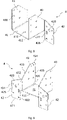
Fig. 8 and Fig. 9 are perspective views, from different angles, of a mounting bracket in an alternative embodiment of the roof window system according to the invention; -
Fig. 10 is a perspective view of the roof window system in an embodiment of the invention; -
Fig. 11 is a perspective view of the embodiment of the roof window system ofFig. 10 during installation into a roof structure; -
Fig. 12 is a detailed view of the roof window system ofFig. 11 ; -
Fig. 13 is a perspective view of another embodiment of the roof window system during installation into a roof structure; -
Fig. 14 is a detailed view of the roof window system ofFig. 13 installed in a roof structure; -
Fig. 15 is an exploded isometric view of the insulating assembly of the roof window system in an embodiment of the invention; -
Figs 16 and 17 are perspective views, from different angles, of the transition member of the insulating assembly in embodiments of the invention; -
Figs 18 and 19 are plan views of the transition member of the insulating assembly in embodiments of the invention; -
Figs 20 to 23 are perspective views, from different angles, of the stabilizing rail in embodiments of the invention; -
Fig. 24 is a partial perspective view of the top part of details of a roof window system in an embodiment of the invention; -
Fig. 25 is a partial perspective view of the top bottom of details of a roof window system in another embodiment of the invention; -
Fig. 26 is a cross-sectional view of a cover assembly of a roof window system in an embodiment of the invention; -
Fig. 27 is a close-up of details ofFig. 27 ; -
Fig. 28a and Fig. 28b show an example of a prior art cover assembly; -
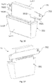
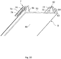
Fig. 29 is a perspective view of the cover assembly in an embodiment of the invention; -
Fig. 30 is a close-up of details ofFig. 29 ; and -
Figs 31 and 32 are perspective views, from different angles, of a tool for dismounting the cover assembly in an embodiment of the roof window system according to the invention; and -
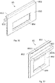
Figs 33 and 34 are perspective views, from different angles, of a tool for dismounting the cover assembly in an embodiment of the roof window system according to the invention. - In the figures of the drawings, embodiments of a roof window system according to the invention are shown.
- Referring initially to
Fig. 1 , aroof structure 2 and a simplified view of theroof window system 1 in an embodiment of the invention are shown Theroof window system 1 comprises twowindow units - A window unit can consist of a single window including frame, sash and pane etc. and/or comprise of more than one single window. It could be two windows placed over and under each other as seen in an inclination of the roof or positioned arbitrarily in extension of each other in the roof surface, and preferably having a common width and thus individual height. Each such window in an over and under configuration could also have unique features relating to the frame, sash and pane etc. It could be a fixed frame with a pane, a frame with a sash being fixed or able to turn around a centre, top, bottom or side axis. Alternatively or additionally, the frame could hold a ventilation device, solar panel etc. Also such a window unit could be of different size, e.g. width, compared with another unit to be placed in the side by side configuration.
- Each
window unit top member side members bottom member roof window system 1 is the combination of the width of first window unit W1, the dimension of a spacing SP between the twowindow units roof window system 1 is the height of any ofwindow units - The
roof structure 2 comprisesrafters roof window system 1 and at the same time at least retain the structural integrity of theroof structure 2, an upperhorizontal trimmer 23, a lowerhorizontal trimmer 24 and avertical trimmer 25 are installed. To aid in the subsequent installation of asupport assembly 3 of theroof window system 1 in theroof structure 2, auxiliary battenpieces 28 are installed opposite the intended position of anupper support beam 31 and alower support beam 32, respectively, which form part of thesupport assembly 3 to be described in further detail below. -
Fig. 2 is a perspective view of theroof structure 2 and of asupport assembly 3 of theroof window system 1 as seen from the interior. Theroof structure 2 furthermore comprises anunderroofing 26 placed over therafters battens 22. Thesupport assembly 3 is shown as from the interior of a building and comprises a set of support beams, here anupper support beam 31 and alower support beam 32, configured to be mounted substantially horizontally in saidroof structure 2 such that thetop member bottom member window unit respective support beam roof window system 1, for instance by using window installation brackets connected to the frame and battens, respectively. -
Fig. 3 is a sectional view and shows in more detail theupper support beam 31 andlower support beam 32 in relation to thewindow unit 11. Visible inFig. 3 is alining panel 95 which at one edge is received in agroove 17 in thetop member 111 of thefirst window unit 11. It is noted thatsuch groove 17 is circumferential and present in all members of the frame of the roof windows constituting the window units. It is also shown that thelining panel 95 is allowed to form a bend between a first portion near thewindow unit 11 and a second inclined portion such that a diverging clearing is formed. By the bend, sufficient insulation is present in the area near thelining panel 95. - The upper and lower parts of the insulating
assembly 5 can be seen placed between thetop frame member 111 and theupper support beam 31 and thebottom frame member 114 and thelower support beam 32. Also it is shown how theunderroofing 26 is arranged with respect to the upper and lower support beams 31, 32 and how asupplementary underroof collar 96 is arranged over thebattens 22 and connected to thetop frame member 111 and how its arranged under the lower batten 22 below thewindow unit 11 and connected to thebottom frame member 114 of thewindow unit 11. Theunderroof collar 96 is brought into overlap with theunderroofing 26. Furthermore, avapour barrier membrane 27 forms part of theroof structure 2 such that the insulation is protected from moisture from the interior. A supplementaryvapour barrier collar 97 is also provided, which at one edge portion is connected to thewindow units vapour barrier membrane 26. Also visible inFig. 3 are twoinstallation battens 29, of which the uppermost installation batten 29 is positioned to extend between theupper support beam 31 and the upperhorizontal trimmer 23, and the lowermost installation batten 29 between thelower support beam 32 and the lowerhorizontal trimmer 24. - Also visible in
Fig. 3 is a flashingarrangement 91 at the top and a flashingarrangement 94 at the bottom which provide a weather-tight transition between thewindow units further flashing arrangements Figs 4 and 5 . -
Fig. 6 and Fig. 7 are respectively an end perspective view of one of the support beams, hereupper support beam 31, at its connection to therafter 21. Thesupport beam 31 has atop surface 311, aside surface 312, aside surface 313, and abottom surface 314. Thesupport beam 31 is inserted in a mountingbracket 4 comprising abase 41, anupstanding flange 43 on either side of thebase 41, and twolegs 42 each connected to aflange 43. The mountingbracket 4 is in turn fastened to therafter 21 by suitable fastening means. The material of the support beams may in principle be chosen arbitrarily, as long as the material has sufficient strength and wear properties. Typically, a wooden material is chosen, and may include laminated wooden beams such as Glulam beams, Kerto® beams etc. which are dimensionally stable, strong and light-weight. - Further details of the mounting
bracket 4 in the embodiment shown will be described in further detail with particular reference toFigs 8 and 9 . Here, it is shown that thebase 41 comprises afirst edge 411 and asecond edge 412. Eachupstanding flange 43 is connected to, in the embodiment shown perpendicularly to, the base 41 at afirst transition edge 431 of theupstanding flange 43 and eachleg 42 is connected to the respectiveupstanding flange 43 at asecond transition edge 432 of theupstanding flange 43. In the embodiment shown, thefirst transition edge 431 is perpendicular to thesecond transition edge 432. - Each
leg 42 comprises an inner freeside edge portion 422 in extension of thesecond transition edge 432 of theupstanding flange 43 such that an upper section of each saidleg 42 extends above a plane of thebase 41 and a lower section of each saidleg 42 extends below the plane of thebase 41. As indicated, thelegs 42 have a relatively large extension in the height direction, perpendicular to the longitudinal direction of therafter 21. In this way, it is possible to fasten the mountingbrackets 4 at such a position that a minimum of fastening elements such as screws or nails are located close to the top of the rafter. In turn, the zone surrounding thewindow units roof structure 2 is rendered free of fastening elements which is advantageous for a number of reasons, including the overall mounting as well as insulation and other climate adaptability properties. - The
base 41, eachleg 42 and eachupstanding flange 43 comprises at least one hole or aperture adapted to receive fastening means such as screws or nails. Here, eachleg 42 is provided with a plurality of holes andapertures bracket 4 to therafter 21. Ahole 413 in thebase 41 is intended to receive fastening means such as a screw driven into thesupport beam upstanding flanges 43. Theupstanding flanges 43 are also provided with a set ofholes 436 serving also to receive screws to be driven into thesupport beam - The installation of the roof window system in the
roof structure 2 comprising a plurality ofrafters trimmer Fig. 6 :
Each mountingbracket 4 is connected to arafter 21 or avertical trimmer 25 bylegs 42 such that the base 41 protrudes from therafter 21 orvertical trimmer 25 and supports abottom surface 314 of therespective support beam brackets 4 are connected to rafters; in case there are trimmers on either side, all mounting brackets are connected thereto. The connection advantageously takes place perpendicularly as shown. In the fastened condition, eachupstanding flange 43 protrudes from therafter 21 orvertical trimmer 25 as the case may be. Thereby, it supports aside surface respective support beam - Referring briefly again to
Fig. 7 , thetop surface 311 of eachsupport beam battens 22 of theroof structure 2 in the mounted condition of theroof window system 1. As mentioned in the above, this positioning is made possible by the particular configuration of the mountingbrackets 4, in particular of thelegs 42. - While the
support assembly 3 has now been installed by means of the mountingbrackets 4 as indicated in the above embodiments, the aperture in theroof structure 2 is preferably provided with insulation and thewindow units Fig. 10 , stabilizingrails respective window unit window installation brackets 15 are connected to the window units in a manner known per se. Turning now toFig. 11 , an insulatingassembly 5 is shown connected to theroof structure 2. - For the description of the stabilizing assembly and the insulating assembly of the roof window system according to the invention, reference is first made jointly to
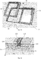
Figs 4 ,10 ,11 and 12 , in which a roof window system comprising twowindow units Figs 5 ,13 and 14 in which a roof window system comprising twowindow units -
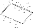
Fig. 15 shows an exploded isometric view of the insulatingassembly 5 of theroof window system 1. The insulatingassembly 5 comprises twoside members top member second bottom member transition members - Each
side member window units member window units - Each
transition member top members bottom members assembly 5, the twoside members bottom members transition members window units outer side members window units - In the embodiment shown, each member of the plurality of top and
bottom members element 5121 and a supportingrail 5122 having a uniform cross-section. The term "standard insulating frame piece" encompasses components of commercially available insulating frames fitting a counterpart roof window of a pre-defined size, for instance within a size range of products. The configuration of an insulating frame piece is well-known per se, for instance from Applicant'sEP 2 677 092 B1assembly 5 furthermore comprises a set of fourconnector brackets 57 configured to connect theside members bottom member rail 5122 of the standard insulating frame piece constituting each member of said plurality of top andbottom members connector bracket 57, preferably comprising a barb or lug. - Referring now to
Figs 16 to 19 , eachtransition member element 551 and anengagement element 552 configured to bring thetransition member bottom members Figs 12 and13 , the insulatingelement 551 comprises an enlargedlower section 5511 and anupper section 5512, the enlargedlower section 5511 being provided with aninclined edge 5513 such that aledge 5514 is formed in the transition area between the upper andlower sections ledge 5514 may in principle have any suitable configuration but preferably surrounds at least in part theupper section 5512 on an inner face and end faces as shown. Here, theengagement element 552 comprises an L-shaped clip with afirst leg 5521 and asecond leg 5522, thefirst leg 5521 being configured to be received in receiving means of the insulatingelement 551, which may take the form of aslot 5515 in an outer side of theupper section 5512 of the insulatingelement 551. Thesecond leg 5522 of the L-shaped clip comprises engagement means configured to engage with corresponding engagement means of the member of said plurality of top andbottom members lug 5523. To ensure continuity, the shape of thetransition member bottom members - Depending on the selected spacing SP between neighbouring
window units transition member Figs 18 and 19 , two different sizes are shown. In principle, the transition members could be chosen to span the spacing between facing sides of neighbouring roof windows placed at an arbitrary distance from each other. Typically, some standard distances are foreseen, but in principle, the insulating assembly could be provided for spacings ranging from almost contact within the neighbouring roof windows to 500 mm within the neighbouring roof windows. In the embodiments shown, two standardized widths of 100 mm and 18 mm are described - The insulating
element 551 of eachtransition member - In the installation situation shown in
Fig. 10 , the insulatingassembly 5 is configured to cooperate with the stabilizingrail 6 positioned in the spacing SP between neighbouringwindow units rails transition members - In a supply condition, the insulating
assembly 5 is supplied as an unassembled kit, in which the twoside members bottom members transition members top members bottom members transition members transition members transition member bottom members transition member bottom members - Turning now to
Figs 20 and21 , a first embodiment of the stabilizingrail 6 is shown. It is noted that a substantially identical, mirror-imaged second stabilizingrail 6b is provided as well. Where appropriate, reference will also be made to a second embodiment of the stabilizingrail 1006 ofFig. 22 and a third embodiment of the stabilizingrail 2006 ofFig. 23 , and to the interaction between respective insulating profiles of the stabilizingrails transition member 55 of theinsulation assembly 6 shown inFigs 24 and 25 , respectively. Only differences between the embodiments will be described in detail. - Just as the overall configuration of the stabilizing assembly itself, each stabilizing
rail profile - One or both stabilizing rails of a set comprises an insulating
profile 61 fastened to the strengtheningprofile 62. The strengtheningprofile 62 comprises means for connection to theside member 113 of onewindow unit 11 of neighbouringwindow units profile 62b of the second stabilizingrail 6b comprises means for connection to theside member 122 of theother window unit 12 of the roof window system. Here, the insulatingprofile 61 has such a thickness tk, tb and depth dk, db that it substantially spans half of the gap G of the spacing SP between facingside members window units roof window system 1. In this way, the insulatingprofiles - The strengthening
profile 62 comprises aconnection flange 621 with connection means 623, 624, 625, 626 for the connection of the stabilizingrail 6; 1006; 2006 to thewindow unit 11. In the embodiment shown, the connection means comprise a set oflugs 623 protruding from a surface of theconnection flange 621 configured to face and match holes in theside member 113 of thewindow unit 11 to which the stabilizingrail 6; 1006; 2006 is connected. Furthermore, the connection means comprise at least one set ofholes apertures 626 for receiving fastening means and/or fittings, the position and number of the at least one set of holes orapertures roof window system 1 and also matching holes provided in theside member 113 of thewindow unit 11. Matching the connection means of the stabilizingrail 6; 1006; 2006 with holes in the side members of the window units facilitates correct positioning and mounting. One example of fastening means isscrews 627 indicated inFigs 10 and13 . The number and position of the fastening means may be chosen in accordance with the height of thewindow units roof window system 1, such that three sets of twoscrews 627 are provided to fasten the stabilizingrail 6 to theside member 113 of thefirst window unit 11 and the stabilizingrail 6b to theside member 122 of thesecond window unit 12, namely one set near the top, one set near the bottom and one set substantially centrally. In case the common height H is larger, more than three sets may be provided, and fewer than three sets ofscrews 627 may be provided, for instance as shown inFig. 13 . - Each stabilizing
rail roof window system 1, typically as substantially corresponding to the common height H of theroof window system 1. At least the insulatingprofile 61 is chosen to have a length corresponding to the full length of the stabilizingrail 6 but the strengtheningprofile 62 has a length which is shorter than the full length of the stabilizingrail 6, such as to leave an end portion at each end of the stabilizingrail 6 in which the insulatingprofile 61 protrudes beyond opposing ends of the strengtheningprofile 62, the length of said end portions being preferably about 10 to 60 mm, more preferably about 40 mm. - Referring now in particular to
Fig. 24 , it is seen how theledge 5514 of thetransition member 55 cooperates with theshoulder 613 and cut-outportion 614 of the insulatingprofile 61 at the top of the roof window system, and also at theinclined edge 5513 with the facingedge 5115 of the firsttop member 511 of the insulating assembly 5 (and correspondingly at the other side of the other stabilizingrail 6b). - Correspondingly, at the bottom of the roof window system in the embodiment of
Fig. 25 , the insulatingprofile 1061 of the first stabilizingrail 1006 is shown in interaction with thetransition member 56. The thickness tb of the insulatingprofile 61 which spans substantially the gap G of the spacing SP between neighbouringwindow units upper section 5512 of thetransition member 56. - Also clearly visible in this figure is the configuration of the second stabilizing
rail 1006b in the mounted condition. This second stabilizingrail 1006b comprises only strengtheningprofile 1062b, which is mounted reversely on thewindow unit 12 as compared with thestrengthening profile 1062 mounted on thewindow unit 11. - In general, the strengthening
profile 62 of the stabilizingrail 6; 1006 comprises afastening flange 622 extending substantially perpendicularly to theconnection flange 621, thus forming an L-shape, thefastening flange 622 being fastened to the insulatingprofile 61 at an under side, facing away from theconnection flange 621, preferably by means of adhesion. Here, the insulatingprofile 61 of the stabilizingrail 6; 1006; 2006 comprises abase section 611 defining said pre-defined thickness tk, tb. The insulatingprofile 61 of the stabilizingrail 6 comprises aledge 612 and ashoulder portion 613 above thebase section 611, and wherein thefastening flange 622 is positioned on theledge 612 such that an upper side of thefastening flange 622 is substantially flush with an upper side of theshoulder portion 613. - In the second embodiment shown in
Fig. 23 , the insulating profile 2061 of the stabilizingrail 2006 comprises abase section 2611 defining said pre-defined thickness tb and anupper section 2615 having a smaller thickness, and wherein theconnection flange 2621 of thestrengthening profile 2062 comprises a foldedflange portion 2627, theconnection flange 2621 and the foldedflange portion 2627 form fastening surfaces relative to theupper section 2615 of the insulating profile 2061. - The insulating
profile 61 of the stabilizingrail 6 is made from a dimensionally stable material having good thermal insulating properties, preferably a polymer foam, such as extruded polyethylene (PE), polypropylene (PP), polyurethane (PU), polyvinylchloride (PVC), expanded polystyrene (EPS), extruded polystyrene (XPS) or mineral wool. For instance, the same material as for the insulatingassembly 5 may be chosen. - The strengthening
profile 62 is made from any suitable material which is capable of performing the function of a reinforcing rail, e.g. with properties like a gusset. Typically, a composite or metal material, such as steel. - Referring now to
Figs 26 and 27 , a first embodiment of a cover assembly is shown, in a disengaged and an engaged position, respectively. The cover assembly is intended to cover the spacing between facing sides of neighbouring roof windows placed at an arbitrary distance from each other. Typically, some standard distances are foreseen, but in principle, the cover assembly could be provided for spacings ranging from a contact within the neighbouring roof windows to 500 mm within the neighbouring roof windows. In the embodiment shown, a standardized width of the gap G of the spacing SP of 100 mm is described. The person skilled in the art would be aware of necessary adaptions to the cover assembly to accommodate other dimensions. - The cover assembly comprises a set of
receiver brackets 7 configured to be connected to the facingside members window units cover plate 8 configured to be brought into releasable engagement with the set ofreceiver brackets 7. For comparison a prior art cover arrangement of a commercially available product traded under the name VELUX® Dormer is shown inFig. 28a and Fig. 28b . - Referring briefly to
Fig. 29 , the set ofreceiver brackets 7 here includes four items. The number may be chosen in dependence of the height of the window units and hence of the roof window system; however, four receiver brackets have been found appropriate for most sizes window units. - As shown, each
receiver bracket 7 is adapted to be installed in agroove 17 inadjacent frame members window units groove 17 is as mentioned in the above circumferential and typically provided in the frame of most roof windows. Where thegroove 17 at the top, bottom and outermost frame members serves to receive thelining panel 95, thegroove 17 of the adjacent frame members serves to receive thereceiver brackets 7. Eachreceiver bracket 7 comprises abase portion 70 from which a set of two second mountingelements 71 protrude to form rounded shapes, asecond engagement portion 72 being here formed near an end of the respective second mountingelement 71. Furthermore, eachreceiver bracket 7 comprises aleg 73 at an end of thesecond engagement portion 72 opposite thebase portion 70. Theengagement portions 72 and thelegs 73 are advantageously symmetrically placed such that the position can be reversed upside-down. Eachleg 73 is received in thegroove 17 of therespective frame member legs 73 to the material of the frame member, one ormore holes 74 are provided in eachleg 73 as shown inFig. 30 in which twoholes 74 are provided and configured to receive fastening means such as screws (not shown). - The
cover plate 8 comprises abase portion 80 from which a set of two first mountingelements 81 protrude, afirst engagement portion 82 being preferably formed near a free end of the respective first mountingelement 81. - The
cover plate 8 comprises anadditional leg 83, preferably provided with ahook 84. Referring toFig. 27 showing the engaged position, it is seen that thehook 84 is placed close to the frame members such that the entry to thegroove 17 is also covered. It is furthermore seen that aside edge 801 of the base portion is located beyond the position of the respective first mountingelement 81. In this way, thecover element 8 overlaps not only the entire spacing SP but also the portion of theside members groove 17 is located. - Common to all frame members in the embodiment shown, however, is that the
circumferential groove 17 also receives thevapour barrier collar 97. The exact configuration of thevapour barrier collar 97 could in principle be chosen in any suitable way but it is preferred that that not only the top, bottom and outermost side members of the window units are provided with portions of thevapour barrier collar 97, but also the spacing SP between facing side members of the two neighbouringwindow units Fig. 26 . Thevapour barrier collar 97 is here formed as a strip spanning the spacing SP between the neighbouringwindow units gasket 971 is included in thevapour barrier collar 97. Thelegs 73 of thereceiver bracket 7 are thus positioned such that thegasket 971 is squeezed between theleg 73 and the bottom of thegroove 17. - To ensure the releasable engagement, the
cover plate 8 comprises a first mountingelement 81 and thereceiver bracket 7 comprises a complementary second mountingelement 71, and the first mounting element and the second mounting element are adapted to be brought into contact with one another. The first mountingelement 81 and the second mountingelement 71 comprises such complementary shapes that movement of thecover plate 8 relative to the receiver bracket orreceiver brackets 7 in a mounting direction is possible while movement in the opposite direction is at least temporarily prevented by afirst engagement portion 82 on the first mountingelement 81 brought into engagement with asecond engagement portion 72 on the second mountingelement 71 to ensure a snap or clip engagement. In principle the first mountingelement 81 and the second mountingelement 71 could be provided at one longitudinal edge of thecover plate 8 and thereceiver bracket 7, respectively; however, it is preferred that they as shown are symmetrically placed along both side edges. - In the embodiment shown, the first and
second engagement portions element 81 forms an angle α with a direction perpendicular to thebase portion 80 of thecover plate 8. The angle α is small, typically about 2 to 5°, and ascertains that safe guidance of thecover plate 8 over thereceiver brackets 7 is ensured. - The first mounting
elements 81 may be said to have the form of a track configured to be guided over and to be received, partially or fully, by the second mountingelements 71. - Once the desired number of
receiver brackets 7 have been connected to the facingside members holes 74 in thelegs 73 and further into theside members cover plate 8 is placed such that the first mountingelements 81 with the respectivefirst engagement portions 82 are guided over the second mountingelements 71 of thereceiver brackets 7, until thefirst engagement portions 82 snap behind thesecond engagement portions 72. During this operation, thelegs 73 also function as a stop of the movement such that the installer will experience a clear indication, for instance in the form of a distinct sound, that the mounted condition has been reached. - Each
receiver bracket 7 is made of a robust material such as metal or an alloy or a plastic compound or a combination thereof, preferably extruded. Thecover plate 8 is typically made of a metal or an alloy or a plastic compound or wood a combination thereof. - While the
cover plate 8 may in principle be disengaged from the receiver bracket orbrackets 7 in any suitable way, ademount tool 85 is provided in an embodiment of the roof window system according to the invention. As shown inFigs 31 and 32 , thedemount tool 85 comprises a substantiallyplane base 850. From thebase 850, afirst flange 851 protrudes at arounded section 852, ending in anedge 8511. Asecond flange 853 protrudes from the base 850 at a distance from thefirst flange 851. Thesecond flange 853 ends in anedge 8531 slightly beyond theedge 8511 of thefirst flange 851. Agrip opening 854 is provided in thebase 850. - In case it is desired to remove the
cover plate 8, thefirst flange 851 of thedemount tool 85 is introduced into the gap behind theleg 83 of thecover plate 8, at the position of thehook 84. During this operation, thesecond flange 853 of thedemount tool 85 overlaps thebase portion 80 of the cover plate in the area of theside edge 801 while thebase 850 of thedemount tool 85 is substantially perpendicular to the plane of thebase portion 80. The user then rotates thedemount tool 85 outwards, i.e. in the direction away from thebase portion 80 of thecover plate 8, by way of a lever rotating about therounded section 852 which in turn abuts a surface of theside member cover plate 8 and thereceiver bracket 7. If needed, the process is repeated at the position of eachreceiver bracket 7 and at both side edges 801 of thecover plate 8. - Another embodiment of a
demount tool 86 is shown inFigs 33 and 34 . Thedemount tool 86 comprises abase 860. From thebase 860, aflange 861 protrudes while ahandle portion 864 is formed oppositely to theflange 861. In case thecover plate 8 is to be removed, theflange 861 of thedemount tool 86 is introduced into the gap behind thecover plate 8 and the engagement between thecover plate 8 and thereceiver bracket 7 is released by handling thedemount tool 86. Anopening 865 is provided in thehandle portion 864 in order to allow hanging thedemount tool 86 on for instance a hook in-between uses. On the back side of thedemount tool 86, shown inFig. 34 ,reinforcement ribs 866 are provided to incur rigidity to thedemount tool 86. - The invention is not limited to the embodiments shown and described in the above, but various modifications and combinations may be carried out.
-
- 1
- roof window system
- 11
- first window unit
- 111
- top member
- 112
- side member
- 113
- side member
- 114
- bottom member
- 12
- second window unit
- 121
- top member
- 122
- side member
- 123
- side member
- 124
- bottom member
- 15
- window installation bracket
- 17
- groove
- 2
- roof structure
- 20
- rafter
- 21
- rafter
- 22
- batten(s)
- 23
- upper horizontal trimmer
- 24
- lower horizontal trimmer
- 25
- vertical trimmer
- 26
- underroofing
- 27
- vapour barrier membrane
- 28
- auxiliary batten piece(s)
- 29
- installation batten(s)
- 3
- support assembly
- 31
- upper support beam
- 311
- top surface
- 312
- side surface
- 313
- side surface
- 314
- bottom surface
- 32
- lower support beam
- 4
- mounting bracket
- 41
- base
- 411
- first edge
- 412
- second edge
- 413
- hole in base
- 42
- leg(s)
- 421
- bottom edge
- 422
- inner free side edge portion
- 423
- upper edge
- 424
- outer edge
- 425
- notch
- 426
- hole(s) in leg
- 427
- oblong aperture
- 428
- larger hole in leg
- 43
- upstanding flange(s)
- 431
- first transition edge of
upstanding flange 43 tobase 41 - 432
- second transition edge of
upstanding flange 43 toleg 42 - 433
- inclined edge portion
- 434
- upper edge
- 435
- outer edge
- 436
- hole(s) in upstanding flange(s)
- 5
- insulating assembly
- 50
- insulating frame
- 511
- first top member
- 5115
- facing edge
- 512
- second top member
- 5121
- insulating element
- 5122
- supporting rail
- 5125
- facing edge
- 52
- side member
- 53
- side member
- 541
- first bottom member
- 542
- second bottom member
- 55
- transition member
- 551
- insulating element
- 5511
- enlarged lower section
- 5512
- upper section
- 5513
- inclined edge
- 5514
- ledge
- 5515
- slot
- 552
- engagement element
- 5521
- first leg
- 5522
- second leg
- 5523
- lug
- 56
- transition member
- 57
- connector bracket
- 6, 6b
- stabilizing rail
- 61, 61b
- insulating profile
- 611
- base section
- 612
- ledge
- 613
- shoulder
- 614
- cut-out (top)
- 615
- cut-out (bottom)
- 62, 62b
- strengthening profile
- 621
- connection flange
- 622
- fastening flange
- 623
- set of lugs
- 624
- set of holes (top)
- 625
- set of holes (bottom)
- 626
- set of apertures
- 627
- fastening means (screws)
- 1006
- stabilizing rail (2nd embodiment)
- 1061
- insulating profile
- 1062
- strengthening profile
- 1006b
- second stabilizing rail
- 1062b
- strengthening profile of second stabilizing rail
- 2006
- stabilizing rail (3rd embodiment)
- 2061
- insulating profile
- 2611
- base section
- 2616
- upper section
- 2062
- strengthening profile
- 2621
- connection flange
- 2627
- folded flange portion
- 2006b
- second stabilizing rail
- 7
- receiver brackets
- 70
- base portion
- 71
- second mounting element
- 72
- second engagement portion
- 73
- leg
- 74
- hole(s)
- 8
- cover plate
- 80
- base portion
- 801
- side edge of base portion
- 81
- first mounting element
- 82
- first engagement portion
- 83
- leg
- 84
- hook
- 85
- demount tool
- 850
- base
- 851
- first flange
- 8511
- edge of first flange
- 852
- rounded section
- 853
- second flange
- 8531
- edge of second flange
- 854
- grip opening
- 86
- demount tool (other embodiment)
- 860
- base
- 861
- flange
- 864
- handle portion
- 865
- opening
- 866
- reinforcement ribs
- 91
- flashing arrangement
- 92
- flashing arrangement
- 93
- flashing arrangment
- 94
- flashing arrangement
- 95
- lining panel
- 96
- underroof collar
- 97
- vapour barrier collar
- 971
- gasket
- SP
- spacing
- G
- gap
- D
- depth
- HWU
- common height of window units
- W1
- width of first window unit
- W2
- width of second window unit
- W
- combined width
- DWU
- common depth of window units
- wk
- width (large)
- wb
- width (small)
- dk
- depth (large)
- db
- depth (small)
- tk
- thickness (large)
- tb
- thickness (small)
- α
- angle
Claims (15)
- A roof window system (1) comprising at least two window units (11, 12) configured to be built in side by side, separated by a pre-defined spacing (SP), in a roof structure (2) of a roof, in particular comprising an inclined roof surface, each window unit (11, 12) comprising a top member (111, 121), two side members (112, 113, 122, 123), and a bottom member (114, 124), said roof window system (1) furthermore comprising a cover assembly spanning the spacing (SP) between facing side members (113, 122) of neighbouring window units (11, 12) in the mounted condition of the roof window system (1),
characterised in that the cover assembly comprises a set of receiver brackets (7) configured to be connected to the facing side members (113, 122) of neighbouring window units (11, 12) and a cover plate (8) configured to be brought into releasable engagement with the set of receiver brackets (7). - A roof window system according to claim 1, wherein each receiver bracket (7) is adapted to be installed in a groove (17) in the facing side members (113, 122) of neighbouring window units (11, 12).
- A roof window system according to claim 2, wherein each receiver bracket (7) comprises at least one leg (73) configured to be received in said groove (17), the leg (73) being preferably provided with one or more holes (74) to receive fastening means.
- A roof window system according to any one of the preceding claims, wherein the cover plate (8) comprises a first mounting element (81) and the receiver bracket (7) comprises a complementary second mounting element (71), and wherein the first mounting element and the second mounting element are adapted to be brought into contact with one another.
- A roof window system according to claim 4, wherein the first mounting element (81) and the second mounting element (71) comprise such complementary shapes that movement of the cover plate (8) relative to the receiver bracket or receiver brackets (7) in a mounting direction is possible while movement in the opposite direction is at least temporarily prevented by a first engagement portion (82) on the first mounting element (81) brought into engagement with a second engagement portion (72) on the second mounting element (71), preferably by a snap or clip engagement.
- A roof window system according to claim 5, wherein the first and second engagement portions (82, 72) are formed as mutually cooperating shapes including a protrusion, an indent, a wave shaped, a barb, a hook-shaped element, a catch-shaped element, a T-shaped cross-section, a V-shaped cross section and an arrow-shaped cross section or any combination thereof.
- A roof window system according to any one of claims 4 to 6, wherein each receiver bracket (7) comprises a base portion (70) from which a set of two second mounting elements (71) protrude to form rounded shapes, preferably symmetrically, more preferably such that one second engagement portion (72) is formed near an end of the respective second mounting element (71).
- A roof window system according to any one of claims 4 to 7, wherein the cover plate (8) comprises a base portion (80) from which a set of two first mounting elements (81) protrude, one first engagement portion (82) being preferably formed near a free end of the respective first mounting element (81).
- A roof window system according to claim 8, wherein each first mounting element (81) forms an angle (α) with a direction perpendicular to the base portion (80) of the cover plate (8), the angle (α) being preferably about 2 to 5°.
- A roof window system according to any one of claims 8 to 9, wherein the cover plate (8) comprises an additional leg (83), preferably provided with a hook (84).
- A roof window system according to any one of the preceding claims, wherein each receiver bracket (7) is made of a metal or an alloy or a plastic compound or a combination thereof, preferably extruded.
- A roof window system according to any one of the preceding claims, wherein the roof window system comprises a plurality of 2 to 6 receiver brackets (7), preferably 4.
- A roof window system according to any one of the preceding claims, wherein the cover plate (8) is made of a metal or an alloy or a plastic compound or wood a combination thereof.
- A roof window system according to any one of the preceding claims, wherein the cover assembly is configured to cover spacings (SP) with a gap (G) between neighbouring window units (11, 12) of substantially 0 to 500 mm, more preferably around 18 mm or 100 mm.
- A roof window system according to any of the preceding claims, wherein the roof window system furthermore comprises a demount tool (85; 86) to provide disengagement of the cover plate (8) from the receiver bracket(s) (7), and wherein the demount tool (85; 86) comprises a substantially plane base (850; 860), from which a first flange (851; 861) protrudes, optionally at a rounded section (852), ending in an edge (8511), and a second flange (853) optionally protruding from the base (850) at a distance from the first flange (851), the second flange (853) ending in an edge (8531) slightly beyond the edge (8511), and wherein said base (850; 860) is provided with a handle (864) or grip opening (854).
Applications Claiming Priority (1)
| Application Number | Priority Date | Filing Date | Title |
|---|---|---|---|
| DKPA202070880A DK181500B1 (en) | 2020-12-30 | 2020-12-30 | A roof window system with a cover assembly |
Publications (3)
| Publication Number | Publication Date |
|---|---|
| EP4023835A1 true EP4023835A1 (en) | 2022-07-06 |
| EP4023835B1 EP4023835B1 (en) | 2023-10-11 |
| EP4023835C0 EP4023835C0 (en) | 2023-10-11 |
Family
ID=79020889
Family Applications (1)
| Application Number | Title | Priority Date | Filing Date |
|---|---|---|---|
| EP21216882.7A Active EP4023835B1 (en) | 2020-12-30 | 2021-12-22 | A roof window system with a cover assembly |
Country Status (4)
| Country | Link |
|---|---|
| EP (1) | EP4023835B1 (en) |
| DK (1) | DK181500B1 (en) |
| HU (1) | HUE064832T2 (en) |
| PL (1) | PL4023835T3 (en) |
Families Citing this family (1)
| Publication number | Priority date | Publication date | Assignee | Title |
|---|---|---|---|---|
| EP4538476A1 (en) * | 2023-10-13 | 2025-04-16 | VKR Holding A/S | Top covering member, a weather-proofing system for a roof penetrating structure, and a sloping roof penetrating window |
Citations (9)
| Publication number | Priority date | Publication date | Assignee | Title |
|---|---|---|---|---|
| US3791088A (en) * | 1971-11-08 | 1974-02-12 | Plasteco Inc | Prefabricated multiple dome units or skylights and composite thereof |
| DE2443098A1 (en) * | 1973-09-10 | 1975-03-20 | Schmidt & Co A | Securement for window or door cladding profile - has projections on clamps fitting grooves in frame and profile one on either side |
| DE3206871C1 (en) * | 1982-02-26 | 1983-06-01 | Velux GmbH - Bauzubehör, 2000 Hamburg | Combination roofing frame for roof windows to be installed next to each other |
| DE19653007A1 (en) * | 1996-12-19 | 1998-06-25 | Markus Kueble | Skylight |
| US6212834B1 (en) * | 1992-06-23 | 2001-04-10 | V. Kann Rasmussen Industri A/S | Flashing arrangement for windows, in particular roof windows |
| EP2568094A1 (en) * | 2011-09-12 | 2013-03-13 | FAKRO PP Spolka z ograniczona odpowiedzialnoscia | A roof window, in particular a roof window apt to be mounted within a set of solar panels |
| EP1581706B1 (en) | 2002-12-16 | 2014-08-20 | VKR Holding A/S | Side flashing member , flashing assembly and roof structure |
| EP2677092B1 (en) | 2012-06-19 | 2015-07-22 | VKR Holding A/S | An insulating frame for a roof window and a method of mounting a roof window |
| DE202019106959U1 (en) * | 2019-12-13 | 2020-01-16 | Roto Frank Dachsystem-Technologie GmbH | Auxiliary rafters, roof window arrangement and roof arrangement |
Family Cites Families (4)
| Publication number | Priority date | Publication date | Assignee | Title |
|---|---|---|---|---|
| DE7920094U1 (en) * | 1979-07-13 | 1979-10-11 | V. Kann Rasmussen Holding A/S, Soeborg (Daenemark) | MOUNTING FOR INCLINED WINDOWS AND PROFILE STRIP FOR SUCH MOUNTING |
| US20110138712A1 (en) * | 2009-12-15 | 2011-06-16 | Christos Demogenes | Skylight roof assembly |
| PL226250B1 (en) * | 2011-01-31 | 2017-06-30 | Fakro Pp Spółka Z Ograniczoną Odpowiedzialnością | A set of tools for roof work, to seal the joint of an assembly composed of at least two structures that penetrate the roof |
| DK179723B1 (en) * | 2017-02-15 | 2019-04-12 | Vkr Holding A/S | A method for attaching a pane element to a sash and a pane module including a pane element |
-
2020
- 2020-12-30 DK DKPA202070880A patent/DK181500B1/en active IP Right Grant
-
2021
- 2021-12-22 HU HUE21216882A patent/HUE064832T2/en unknown
- 2021-12-22 PL PL21216882.7T patent/PL4023835T3/en unknown
- 2021-12-22 EP EP21216882.7A patent/EP4023835B1/en active Active
Patent Citations (9)
| Publication number | Priority date | Publication date | Assignee | Title |
|---|---|---|---|---|
| US3791088A (en) * | 1971-11-08 | 1974-02-12 | Plasteco Inc | Prefabricated multiple dome units or skylights and composite thereof |
| DE2443098A1 (en) * | 1973-09-10 | 1975-03-20 | Schmidt & Co A | Securement for window or door cladding profile - has projections on clamps fitting grooves in frame and profile one on either side |
| DE3206871C1 (en) * | 1982-02-26 | 1983-06-01 | Velux GmbH - Bauzubehör, 2000 Hamburg | Combination roofing frame for roof windows to be installed next to each other |
| US6212834B1 (en) * | 1992-06-23 | 2001-04-10 | V. Kann Rasmussen Industri A/S | Flashing arrangement for windows, in particular roof windows |
| DE19653007A1 (en) * | 1996-12-19 | 1998-06-25 | Markus Kueble | Skylight |
| EP1581706B1 (en) | 2002-12-16 | 2014-08-20 | VKR Holding A/S | Side flashing member , flashing assembly and roof structure |
| EP2568094A1 (en) * | 2011-09-12 | 2013-03-13 | FAKRO PP Spolka z ograniczona odpowiedzialnoscia | A roof window, in particular a roof window apt to be mounted within a set of solar panels |
| EP2677092B1 (en) | 2012-06-19 | 2015-07-22 | VKR Holding A/S | An insulating frame for a roof window and a method of mounting a roof window |
| DE202019106959U1 (en) * | 2019-12-13 | 2020-01-16 | Roto Frank Dachsystem-Technologie GmbH | Auxiliary rafters, roof window arrangement and roof arrangement |
Also Published As
| Publication number | Publication date |
|---|---|
| PL4023835T3 (en) | 2024-04-22 |
| HUE064832T2 (en) | 2024-05-28 |
| DK202070880A1 (en) | 2022-07-05 |
| DK181500B1 (en) | 2024-03-12 |
| EP4023835B1 (en) | 2023-10-11 |
| EP4023835C0 (en) | 2023-10-11 |
Similar Documents
| Publication | Publication Date | Title |
|---|---|---|
| CA2166587C (en) | Adjustable width panel assembly | |
| US4316351A (en) | Thermally insulated building construction panel and a wall formed from such panels | |
| US4133161A (en) | Panel assemblies and methods of forming same | |
| US5694728A (en) | Vinyl siding system | |
| US7210273B2 (en) | Panel attachment system | |
| US7472523B2 (en) | Rainscreen clapboard siding | |
| EP3680416B1 (en) | A connector element for a flashing assembly for use in a roof window arrangement and a method for weather proofing a roof window arrangement | |
| US4674242A (en) | Fastener stud for accommodation of drywall to inner wall and ceiling surfaces | |
| US5581969A (en) | Prefabricated building element | |
| EP0609987A1 (en) | Interlocking building panel | |
| EP4023835B1 (en) | A roof window system with a cover assembly | |
| US4373315A (en) | Building elements and building methods | |
| US8733043B1 (en) | Corner block building trim | |
| EP4023834B1 (en) | A roof window system with a mounting assembly and method of installing such a roof window system | |
| EP4023832B1 (en) | A roof window system with an insulating frame | |
| EP4023833B1 (en) | A roof window system with a stabilizing assembly | |
| WO1988003588A1 (en) | Panel mounting system | |
| AU2003288482A1 (en) | A composite roof panel | |
| US20060096217A1 (en) | Cladding | |
| US9140051B1 (en) | Window and method | |
| JPH11172886A (en) | Horizontal torso for vertical siding installation | |
| JP2909885B2 (en) | Vertical roof structure | |
| US4779392A (en) | Building wall | |
| EP0277226B1 (en) | Improved panel unit | |
| WO2000023672A1 (en) | Screwless covering system |
Legal Events
| Date | Code | Title | Description |
|---|---|---|---|
| PUAI | Public reference made under article 153(3) epc to a published international application that has entered the european phase |
Free format text: ORIGINAL CODE: 0009012 |
|
| STAA | Information on the status of an ep patent application or granted ep patent |
Free format text: STATUS: THE APPLICATION HAS BEEN PUBLISHED |
|
| AK | Designated contracting states |
Kind code of ref document: A1 Designated state(s): AL AT BE BG CH CY CZ DE DK EE ES FI FR GB GR HR HU IE IS IT LI LT LU LV MC MK MT NL NO PL PT RO RS SE SI SK SM TR |
|
| STAA | Information on the status of an ep patent application or granted ep patent |
Free format text: STATUS: REQUEST FOR EXAMINATION WAS MADE |
|
| 17P | Request for examination filed |
Effective date: 20230105 |
|
| RBV | Designated contracting states (corrected) |
Designated state(s): AL AT BE BG CH CY CZ DE DK EE ES FI FR GB GR HR HU IE IS IT LI LT LU LV MC MK MT NL NO PL PT RO RS SE SI SK SM TR |
|
| GRAP | Despatch of communication of intention to grant a patent |
Free format text: ORIGINAL CODE: EPIDOSNIGR1 |
|
| STAA | Information on the status of an ep patent application or granted ep patent |
Free format text: STATUS: GRANT OF PATENT IS INTENDED |
|
| INTG | Intention to grant announced |
Effective date: 20230620 |
|
| GRAS | Grant fee paid |
Free format text: ORIGINAL CODE: EPIDOSNIGR3 |
|
| GRAA | (expected) grant |
Free format text: ORIGINAL CODE: 0009210 |
|
| STAA | Information on the status of an ep patent application or granted ep patent |
Free format text: STATUS: THE PATENT HAS BEEN GRANTED |
|
| AK | Designated contracting states |
Kind code of ref document: B1 Designated state(s): AL AT BE BG CH CY CZ DE DK EE ES FI FR GB GR HR HU IE IS IT LI LT LU LV MC MK MT NL NO PL PT RO RS SE SI SK SM TR |
|
| REG | Reference to a national code |
Ref country code: GB Ref legal event code: FG4D |
|
| REG | Reference to a national code |
Ref country code: CH Ref legal event code: EP |
|
| REG | Reference to a national code |
Ref country code: DE Ref legal event code: R096 Ref document number: 602021005818 Country of ref document: DE |
|
| REG | Reference to a national code |
Ref country code: IE Ref legal event code: FG4D |
|
| U01 | Request for unitary effect filed |
Effective date: 20231011 |
|
| U07 | Unitary effect registered |
Designated state(s): AT BE BG DE DK EE FI FR IT LT LU LV MT NL PT SE SI Effective date: 20231017 |
|
| U20 | Renewal fee for the european patent with unitary effect paid |
Year of fee payment: 3 Effective date: 20231116 |
|
| PG25 | Lapsed in a contracting state [announced via postgrant information from national office to epo] |
Ref country code: GR Free format text: LAPSE BECAUSE OF FAILURE TO SUBMIT A TRANSLATION OF THE DESCRIPTION OR TO PAY THE FEE WITHIN THE PRESCRIBED TIME-LIMIT Effective date: 20240112 |
|
| PG25 | Lapsed in a contracting state [announced via postgrant information from national office to epo] |
Ref country code: IS Free format text: LAPSE BECAUSE OF FAILURE TO SUBMIT A TRANSLATION OF THE DESCRIPTION OR TO PAY THE FEE WITHIN THE PRESCRIBED TIME-LIMIT Effective date: 20240211 |
|
| PG25 | Lapsed in a contracting state [announced via postgrant information from national office to epo] |
Ref country code: ES Free format text: LAPSE BECAUSE OF FAILURE TO SUBMIT A TRANSLATION OF THE DESCRIPTION OR TO PAY THE FEE WITHIN THE PRESCRIBED TIME-LIMIT Effective date: 20231011 |
|
| PG25 | Lapsed in a contracting state [announced via postgrant information from national office to epo] |
Ref country code: IS Free format text: LAPSE BECAUSE OF FAILURE TO SUBMIT A TRANSLATION OF THE DESCRIPTION OR TO PAY THE FEE WITHIN THE PRESCRIBED TIME-LIMIT Effective date: 20240211 Ref country code: GR Free format text: LAPSE BECAUSE OF FAILURE TO SUBMIT A TRANSLATION OF THE DESCRIPTION OR TO PAY THE FEE WITHIN THE PRESCRIBED TIME-LIMIT Effective date: 20240112 Ref country code: ES Free format text: LAPSE BECAUSE OF FAILURE TO SUBMIT A TRANSLATION OF THE DESCRIPTION OR TO PAY THE FEE WITHIN THE PRESCRIBED TIME-LIMIT Effective date: 20231011 |
|
| REG | Reference to a national code |
Ref country code: HU Ref legal event code: AG4A Ref document number: E064832 Country of ref document: HU |
|
| PG25 | Lapsed in a contracting state [announced via postgrant information from national office to epo] |
Ref country code: RS Free format text: LAPSE BECAUSE OF FAILURE TO SUBMIT A TRANSLATION OF THE DESCRIPTION OR TO PAY THE FEE WITHIN THE PRESCRIBED TIME-LIMIT Effective date: 20231011 Ref country code: NO Free format text: LAPSE BECAUSE OF FAILURE TO SUBMIT A TRANSLATION OF THE DESCRIPTION OR TO PAY THE FEE WITHIN THE PRESCRIBED TIME-LIMIT Effective date: 20240111 Ref country code: HR Free format text: LAPSE BECAUSE OF FAILURE TO SUBMIT A TRANSLATION OF THE DESCRIPTION OR TO PAY THE FEE WITHIN THE PRESCRIBED TIME-LIMIT Effective date: 20231011 |
|
| REG | Reference to a national code |
Ref country code: DE Ref legal event code: R097 Ref document number: 602021005818 Country of ref document: DE |
|
| PG25 | Lapsed in a contracting state [announced via postgrant information from national office to epo] |
Ref country code: SK Free format text: LAPSE BECAUSE OF FAILURE TO SUBMIT A TRANSLATION OF THE DESCRIPTION OR TO PAY THE FEE WITHIN THE PRESCRIBED TIME-LIMIT Effective date: 20231011 |
|
| PG25 | Lapsed in a contracting state [announced via postgrant information from national office to epo] |
Ref country code: SM Free format text: LAPSE BECAUSE OF FAILURE TO SUBMIT A TRANSLATION OF THE DESCRIPTION OR TO PAY THE FEE WITHIN THE PRESCRIBED TIME-LIMIT Effective date: 20231011 Ref country code: SK Free format text: LAPSE BECAUSE OF FAILURE TO SUBMIT A TRANSLATION OF THE DESCRIPTION OR TO PAY THE FEE WITHIN THE PRESCRIBED TIME-LIMIT Effective date: 20231011 Ref country code: RO Free format text: LAPSE BECAUSE OF FAILURE TO SUBMIT A TRANSLATION OF THE DESCRIPTION OR TO PAY THE FEE WITHIN THE PRESCRIBED TIME-LIMIT Effective date: 20231011 |
|
| PLBE | No opposition filed within time limit |
Free format text: ORIGINAL CODE: 0009261 |
|
| STAA | Information on the status of an ep patent application or granted ep patent |
Free format text: STATUS: NO OPPOSITION FILED WITHIN TIME LIMIT |
|
| PG25 | Lapsed in a contracting state [announced via postgrant information from national office to epo] |
Ref country code: MC Free format text: LAPSE BECAUSE OF FAILURE TO SUBMIT A TRANSLATION OF THE DESCRIPTION OR TO PAY THE FEE WITHIN THE PRESCRIBED TIME-LIMIT Effective date: 20231011 |
|
| PG25 | Lapsed in a contracting state [announced via postgrant information from national office to epo] |
Ref country code: MC Free format text: LAPSE BECAUSE OF FAILURE TO SUBMIT A TRANSLATION OF THE DESCRIPTION OR TO PAY THE FEE WITHIN THE PRESCRIBED TIME-LIMIT Effective date: 20231011 |
|
| 26N | No opposition filed |
Effective date: 20240712 |
|
| REG | Reference to a national code |
Ref country code: IE Ref legal event code: MM4A |
|
| PG25 | Lapsed in a contracting state [announced via postgrant information from national office to epo] |
Ref country code: IE Free format text: LAPSE BECAUSE OF NON-PAYMENT OF DUE FEES Effective date: 20231222 |
|
| PG25 | Lapsed in a contracting state [announced via postgrant information from national office to epo] |
Ref country code: IE Free format text: LAPSE BECAUSE OF NON-PAYMENT OF DUE FEES Effective date: 20231222 |
|
| U20 | Renewal fee for the european patent with unitary effect paid |
Year of fee payment: 4 Effective date: 20241107 |
|
| PG25 | Lapsed in a contracting state [announced via postgrant information from national office to epo] |
Ref country code: CY Free format text: LAPSE BECAUSE OF FAILURE TO SUBMIT A TRANSLATION OF THE DESCRIPTION OR TO PAY THE FEE WITHIN THE PRESCRIBED TIME-LIMIT; INVALID AB INITIO Effective date: 20211222 |
|
| PG25 | Lapsed in a contracting state [announced via postgrant information from national office to epo] |
Ref country code: TR Free format text: LAPSE BECAUSE OF FAILURE TO SUBMIT A TRANSLATION OF THE DESCRIPTION OR TO PAY THE FEE WITHIN THE PRESCRIBED TIME-LIMIT Effective date: 20231011 |
|
| U20 | Renewal fee for the european patent with unitary effect paid |
Year of fee payment: 5 Effective date: 20251110 |
|
| REG | Reference to a national code |
Ref country code: CH Ref legal event code: U11 Free format text: ST27 STATUS EVENT CODE: U-0-0-U10-U11 (AS PROVIDED BY THE NATIONAL OFFICE) Effective date: 20260101 |
|
| PGFP | Annual fee paid to national office [announced via postgrant information from national office to epo] |
Ref country code: GB Payment date: 20251114 Year of fee payment: 5 |
|
| PGFP | Annual fee paid to national office [announced via postgrant information from national office to epo] |
Ref country code: HU Payment date: 20251127 Year of fee payment: 5 |
|
| PGFP | Annual fee paid to national office [announced via postgrant information from national office to epo] |
Ref country code: CZ Payment date: 20251201 Year of fee payment: 5 |
|
| PGFP | Annual fee paid to national office [announced via postgrant information from national office to epo] |
Ref country code: PL Payment date: 20251117 Year of fee payment: 5 |
|
| PGFP | Annual fee paid to national office [announced via postgrant information from national office to epo] |
Ref country code: CH Payment date: 20260101 Year of fee payment: 5 |