EP4023807A1 - Clothes treatment apparatus - Google Patents
Clothes treatment apparatus Download PDFInfo
- Publication number
- EP4023807A1 EP4023807A1 EP20857236.2A EP20857236A EP4023807A1 EP 4023807 A1 EP4023807 A1 EP 4023807A1 EP 20857236 A EP20857236 A EP 20857236A EP 4023807 A1 EP4023807 A1 EP 4023807A1
- Authority
- EP
- European Patent Office
- Prior art keywords
- coil
- tub
- drum
- base
- treating apparatus
- Prior art date
- Legal status (The legal status is an assumption and is not a legal conclusion. Google has not performed a legal analysis and makes no representation as to the accuracy of the status listed.)
- Pending
Links
Images





Classifications
-
- D—TEXTILES; PAPER
- D06—TREATMENT OF TEXTILES OR THE LIKE; LAUNDERING; FLEXIBLE MATERIALS NOT OTHERWISE PROVIDED FOR
- D06F—LAUNDERING, DRYING, IRONING, PRESSING OR FOLDING TEXTILE ARTICLES
- D06F39/00—Details of washing machines not specific to a single type of machines covered by groups D06F9/00 - D06F27/00
- D06F39/04—Heating arrangements
-
- D—TEXTILES; PAPER
- D06—TREATMENT OF TEXTILES OR THE LIKE; LAUNDERING; FLEXIBLE MATERIALS NOT OTHERWISE PROVIDED FOR
- D06F—LAUNDERING, DRYING, IRONING, PRESSING OR FOLDING TEXTILE ARTICLES
- D06F58/00—Domestic laundry dryers
- D06F58/20—General details of domestic laundry dryers
- D06F58/26—Heating arrangements, e.g. gas heating equipment
-
- H—ELECTRICITY
- H05—ELECTRIC TECHNIQUES NOT OTHERWISE PROVIDED FOR
- H05B—ELECTRIC HEATING; ELECTRIC LIGHT SOURCES NOT OTHERWISE PROVIDED FOR; CIRCUIT ARRANGEMENTS FOR ELECTRIC LIGHT SOURCES, IN GENERAL
- H05B6/00—Heating by electric, magnetic or electromagnetic fields
- H05B6/02—Induction heating
- H05B6/10—Induction heating apparatus, other than furnaces, for specific applications
- H05B6/105—Induction heating apparatus, other than furnaces, for specific applications using a susceptor
-
- H—ELECTRICITY
- H05—ELECTRIC TECHNIQUES NOT OTHERWISE PROVIDED FOR
- H05B—ELECTRIC HEATING; ELECTRIC LIGHT SOURCES NOT OTHERWISE PROVIDED FOR; CIRCUIT ARRANGEMENTS FOR ELECTRIC LIGHT SOURCES, IN GENERAL
- H05B6/00—Heating by electric, magnetic or electromagnetic fields
- H05B6/02—Induction heating
- H05B6/36—Coil arrangements
- H05B6/362—Coil arrangements with flat coil conductors
-
- H—ELECTRICITY
- H05—ELECTRIC TECHNIQUES NOT OTHERWISE PROVIDED FOR
- H05B—ELECTRIC HEATING; ELECTRIC LIGHT SOURCES NOT OTHERWISE PROVIDED FOR; CIRCUIT ARRANGEMENTS FOR ELECTRIC LIGHT SOURCES, IN GENERAL
- H05B6/00—Heating by electric, magnetic or electromagnetic fields
- H05B6/02—Induction heating
- H05B6/36—Coil arrangements
- H05B6/42—Cooling of coils
-
- H—ELECTRICITY
- H05—ELECTRIC TECHNIQUES NOT OTHERWISE PROVIDED FOR
- H05B—ELECTRIC HEATING; ELECTRIC LIGHT SOURCES NOT OTHERWISE PROVIDED FOR; CIRCUIT ARRANGEMENTS FOR ELECTRIC LIGHT SOURCES, IN GENERAL
- H05B2206/00—Aspects relating to heating by electric, magnetic, or electromagnetic fields covered by group H05B6/00
- H05B2206/02—Induction heating
- H05B2206/022—Special supports for the induction coils
Definitions
- the present disclosure relates to a laundry treating apparatus.
- a laundry treating apparatus includes a washing machine or a dryer.
- the washing machine is an apparatus that washes clothes, bedding, and the like (hereinafter, a 'laundry') through processes such as washing, rinsing, dehydration, and the like to remove contamination from the laundry using water, detergent, and a mechanical action
- the dryer is an apparatus for drying clothes that have been washed or wet clothes (hereinafter, the 'laundry') by exposing the laundry to a high temperature.
- the washing machine needs to increase a temperature of the laundry in order to increase a washing efficiency of the laundry.
- the washing machine needs to increase the temperature of the laundry for sterilization of the laundry.
- the washing machine increased the temperature of the laundry by receiving hot water directly from an external water supply source, or increased the temperature of the laundry indirectly by having a separate heater to heat washing water in which the laundry is immersed.
- the conventional washing machine had to supply the washing water to a vertical level at which all the laundry is submerged and had to also heat the washing water in order to increase the temperature of the laundry. This resulted in unnecessary waste of material and energy.
- the dryer performed a drying cycle by heating air with the heater and exposing the heated air to the laundry to evaporate moisture contained in the laundry.
- the induction module is disposed on an outer circumferential surface of the tub to heat the drum.
- a drying function may be increased by increasing the temperature of the air passing through the drum without unnecessary heating of the washing water.
- a time required for the heating may be saved because the drum is directly heated without heating the washing water. Therefore, the laundry treating apparatus including the induction module may increase energy efficiency by preventing the unnecessary energy waste compared to the conventional washing machine, and shorten a washing time, so that a user may wash the laundry conveniently.
- the laundry treating apparatus including the induction module may exert sufficient washing effect even with a small amount of energy, the washing efficiency may be increased, thereby increasing user satisfaction.
- the drum is rapidly heated by the induction module, so that there is a risk of a safety accident. Therefore, a need for a safety device to prevent such accident and to secure product reliability is increasing.
- a component for blocking power supplied to the laundry treating apparatus may be stably disposed at an appropriate position when a temperature is equal to or higher than a predetermined temperature.
- a laundry treating apparatus including an induction heater module and a safety apparatus for preventing overheating of a drum.
- a laundry treating apparatus in which the safety apparatus is formed in a shape of a fuse.
- a laundry treating apparatus in which one blocking assembly, which is the safety apparatus, simultaneously contacts a coil base and a tub to prevent overheating of a coil or the drum.
- a laundry treating apparatus in which the blocking assembly is disposed so as to be fixed to a bottom of the coil and the tub by being pressed and deformed.
- a laundry treating apparatus in which the blocking assembly is located in a region adjacent to the coil base and a region adjacent to a center of the drum in an axial direction, that is, a region that may have a high temperature.
- a laundry treating apparatus in which the blocking assembly is disposed at a location where an influence of a cooling fan is small in consideration of interference with tub surroundings.
- a laundry treating apparatus including a tub, a drum accommodating laundry therein and made of a metal material, and an induction module disposed on an outer surface of the tub and generating an electromagnetic field to heat a circumferential surface of the drum, wherein the induction module includes a coil formed by winding a wire applied with a current, wherein the coil generates a magnetic field, a base housing mounted on an outer circumferential surface of the tub to accommodate the coil therein, and a blocking member disposed to be simultaneously in contact with the base housing and the tub to block the current when being heated to a temperature equal to or higher than a preset temperature by at least one of an amount of heat transferred from the coil and an amount of heat transferred from the drum.
- a laundry treating apparatus including a tube surrounding the blocking member and having elasticity
- the base housing includes a base for supporting the coil, a fixing rib extending from the base to define a coil slot for the coil to be accommodated, and a support rib extending downwardly of the base to provide a space for accommodating the blocking assembly therein, wherein the blocking member is pressed in contact with the base and the tub, and the tub includes an induction module coupling portion formed on an outer circumferential surface thereof, wherein the base includes a coupling portion coupled to the outer surface of the tub, and the base is formed in a plate shape having the same curvature as the outer circumferential surface of the tub.
- thermofuse a laundry treating apparatus in which the blocking member is a thermofuse.
- a laundry treating apparatus further including a module cover coupled to the base, wherein at least one of the module cover and the support rib includes an outermost support rib extending downwardly from an end thereof, wherein the blocking member is disposed to be pressed between the outermost support rib and the support rib, wherein the support rib is disposed to be biased on both sides of the base in a direction perpendicular to a longitudinal axis of the drum.
- the base housing further includes a module cover coupled to the base, wherein a coil cooler for cooling the coil is coupled to the module cover and the coil cooler is coupled to a center of the module cover, wherein the blocking member is disposed to be spaced apart from the coil cooler by a predetermined distance.
- the coil includes a pair of straight portions extending in a longitudinal direction of the tub and a curved portion for connecting the straight portions to each other, wherein the coil includes a front coil portion including the curved portion disposed adjacent to a front portion of the tub, an intermediate coil portion including the straight portion, and a rear coil portion including the curved portion disposed adjacent to a rear portion of the tub, wherein the blocking member is disposed below a portion of the base housing where the intermediate coil portion is located, wherein the blocking assembly receives heat by at least two turns of the wire.
- a laundry treating apparatus in which one blocking member is disposed.
- an embodiment of the present disclosure may provide a laundry treating apparatus including a cabinet, a tub disposed inside the cabinet and accommodating washing water therein, a drum rotatably disposed inside the tub to accommodate laundry therein, wherein the drum is made of a metal material, and an induction module spaced apart from the drum and heating the drum by generating an electromagnetic field, wherein the induction module includes a coil formed by winding a wire applied with a current, wherein the coil generates a magnetic field, a base housing mounted on an outer circumferential surface of the tub to accommodate the coil therein, and a blocking member disposed between the base housing and the tub to selectively block the current applied to the coil.
- the blocking member may block the current applied to the coil when at least one of the tub, the coil, and the base housing is heated to have a temperature equal to or higher than a preset temperature.
- the base housing may include a base for providing a space for accommodating the coil therein, a fixing rib extending from the base in a direction away from the tub to define a coil slot for the coil to be wound, and a support rib extending from the base toward the tub to define a separation space between the base and the tub, and the blocking member may be located in the separation space.
- the coil slot may include an innermost coil slot defined closest to a center of the base among the coil slots, and an outermost coil slot defined farthest from the center of the base among the coil slots, and the blocking member may be disposed at a position spaced apart from a bottom of the innermost coil slot in a left direction or a right direction.
- the blocking member may be located below the outermost coil slot.
- the blocking member may be disposed at a position spaced apart from a bottom of the outermost coil slot in a direction away from the innermost coil slot.
- the induction module may further include a tube for surrounding the blocking member and in contact with each of the base and the tub.
- the tube may be made of an elastic material and may be press-fitted and fixed to the base and the support rib.
- the base housing may be disposed above the tub.
- the base housing may further include a module cover coupled to a top surface of the base to cover the coil, at least one of the module cover and the support rib may include an outermost support rib extending toward the tub from at least one of both ends thereof in a left and right direction, and the tube may be press-fitted and fixed between the outermost support rib and the support rib.
- an embodiment of the present disclosure may provide a laundry treating apparatus including a cabinet, a tub disposed inside the cabinet and accommodating washing water therein, a drum rotatably disposed inside the tub to accommodate laundry therein, wherein the drum is made of a metal material, and an induction module spaced apart from the drum and heating the drum by generating an electromagnetic field, wherein the induction module includes a coil formed by winding a wire applied with a current, wherein the coil generates a magnetic field, a base housing mounted on an outer circumferential surface of the tub to accommodate the coil therein, and a blocking member for selectively blocking the current applied to the coil, wherein the coil includes a pair of straight portions extending in a front and rear direction and a curved portion connecting the straight portions to each other and located above the tub and corresponding to a front portion or a rear portion of the tub, wherein the blocking member is located below the straight portion.
- the blocking member may be disposed between the base housing and the tub.
- the blocking member may be disposed at a position spaced apart from the curved portion in the front and rear direction.
- the base housing may be disposed above the tub.
- the base housing may includes a base for providing a space in which the coil is accommodated, and a module cover coupled to the base to cover the coil, and a coil cooler for forming an airflow to cool the coil may be formed on the module cover.
- the coil cooler may include a fan housing coupled to the module cover and a fan positioned in the fan housing to form the airflow, and the blocking member may be spaced apart from a center of rotation of the fan.
- the blocking member may be spaced apart from the fan housing.
- the blocking member may be spaced apart from the fan housing in a left or right direction.
- a center of the fan housing and a center of the fan may coincide.
- the tub may include a module coupling portion formed on an outer circumferential surface of the tub, and the base housing may include a coupling portion fastened to and fixed to the module coupling portion.
- the blocking member may be a thermofuse.
- One blocking member may be disposed.
- the laundry treating apparatus may reduce the time required for the washing by directly heating the drum.
- the safety may be guaranteed while heating the drum quickly.
- market competitiveness may be secured by reducing the manufacturing cost for preventing the overheating of the coil and the drum.
- the overheating of the coil and the drum may be effectively sensed.
- the component that senses the overheating of the coil and the drum may be stably installed so as not to be removed.
- the safety may be guaranteed even when the external impact is applied.
- a laundry treating apparatus may include a cabinet 10 for forming an appearance thereof, a tub 20, a drum 30, and an induction module 70 for heating the drum 30.
- the tub 20 may be disposed inside the cabinet 10 to accommodate the drum therein.
- An opening may be defined in a front surface of the tub.
- the drum 30 is rotatably disposed inside the tub and accommodates laundry therein. Likewise, an opening may be defined in a front surface of the drum. The laundry may be put into the drum through the openings of the tub and the drum.
- the induction module 70 may heat the drum by generating an electromagnetic field.
- the induction module 70 may be disposed on an outer circumferential surface of the tub 20.
- the tub 20 that provides an accommodation space therein and has the opening defined in the front surface thereof, the drum 30, which is made of a conductor, that is rotatably disposed in the accommodation space and accommodates the laundry therein, and the induction module disposed on the outer circumferential surface of the tub 20 to heat the drum 30 with the electromagnetic field may be included.
- the tub 20 and the drum 30 may be formed in a cylindrical shape. Accordingly, inner circumferential surfaces and outer circumferential surfaces of the tub 20 and the drum 30 may be formed in a substantially cylindrical shape.
- FIG. 1 shows a laundry treating apparatus in which the drum 30 is rotated with respect to a rotation axis parallel to the ground.
- the laundry treating apparatus may further include a driver 40 for rotating the drum 30 inside the tub 20.
- the driver 40 includes a motor 41, and the motor includes a stator and a rotor.
- the rotor may be connected to a rotation shaft 42, and the rotation shaft 42 may be connected to the drum 30 to rotate the drum 30 inside the tub 20.
- the driving unit 40 may include a spider 43.
- the spider 43 which is a component for connecting the drum 30 and the rotation shaft 42 to each other, may be referred to as a component for uniformly and stably transmitting a rotational force of the rotation shaft 42 to the drum 30.
- the spider 43 is coupled to the drum 30 in a form of being at least partially inserted into a rear wall of the drum 30.
- the rear wall of the drum 30 is formed in a shape recessed into the drum.
- the spider 43 may be coupled in a shape of being further inserted into the drum 30 at a center of rotation of the drum 30. Therefore, the laundry is not accommodated at a rear end of the drum 30 due to the spider 43.
- a lifter 50 may be disposed inside the drum 30.
- a plurality of lifters 50 may be disposed along a circumferential direction of the drum.
- the lifter 50 performs a function of stirring the laundry. For example, as the drum rotates, the lifter raises the laundry upwards. The laundry moved upwards is separated from the lifter by gravity and falls downwards. Washing may be performed by an impact force caused by such falling of the laundry. In one example, the stirring of the laundry may improve a drying efficiency.
- the laundry may be evenly distributed in a front and rear direction inside the drum. Therefore, the lifter may be formed extending from the rear end to a front end of the drum.
- the induction module is an apparatus for heating the drum 30.
- the induction module 70 may include a coil 71 capable of generating a magnetic field by receiving a current to generate an eddy current in the drum, and a module cover 72 for accommodating the coil 71 therein.
- the module cover 72 may be formed in a shape of a box with one surface open. That is, the module cover 72 may be formed in a shape of a box in which a surface facing the drum is opened and a surface opposite thereto is closed. Accordingly, the coil 71 is positioned inside the module cover 72 or the module cover 72 covers a top of the coil 71. The module cover 72 functions to protect the coil 71 from the outside. In addition, as will be described later, the module cover 72 defines an air flow space between the module cover 72 and the coil 71 to cool the coil 71.
- the shape of the module cover 72 is not limited to the box shape with one surface open. As will be described later, the module cover 72 may be formed in a shape including a base 741.
- the coil 71 may heat the drum 30 to increase an internal temperature of the drum 30 as well as a temperature of the drum 30 itself. Therefore, washing water in contact with the drum 30 may be heated through the heating of the drum 30 and the laundry in contact with the inner circumferential surface of the drum 30 may be heated. In one example, the laundry that does not come into contact with the inner circumferential surface of the drum 30 may also be heated by raising the internal temperature of the drum. Therefore, it is possible to increase the temperatures of the washing water and the laundry and an ambient temperature of the interior of the drum to enhance a washing effect, as well as, increase the temperatures of the laundry and the drum and the ambient temperature of the interior of the drum for drying the laundry.
- a wire is wound to form the coil 71, and thus, the coil 71 has a center.
- the current flows while rotating around the center of the coil 71 because of the shape of the coil 71. Accordingly, a magnetic field in a vertical direction passing through the center of the coil 71 is generated.
- an AC magnetic field whose direction changes with time is formed.
- the AC magnetic field generates an induced magnetic field whose direction is opposite to that of the AC magnetic field in an adjacent conductor, and a change in the induced magnetic field generates an induced current in the conductor.
- the induced current and the induced magnetic field may be understood as a form of inertia with respect to changes in electric and magnetic fields.
- the drum 30 when the drum 30 is the conductor, the eddy current or a vortex current, which is a kind of the induced current, is generated in the drum 30 by the induced magnetic field generated by the coil 71.
- the eddy current is dissipated and converted into heat by a resistance of the conductor of the drum 30. That is, as a result, the drum 30 is heated by the heat generated by the resistance, and the internal temperature of the drum 30 is increased as the drum 30 is heated.
- the drum 30 when the drum 30 is a conductor made of a magnetic material such as iron (Fe), the drum 30 may be heated by the AC current of the coil 71 disposed on the tub 20.
- Fe iron
- a drum used in a conventional laundry treating apparatus that is, a drum in a laundry treating apparatus in a form of a heat pump or in a laundry treating apparatus using an electric heater (a sheath heater), may be used as it is in the laundry treating apparatus to which the induction module is applied.
- the induction module including the coil 71 and the module cover 72 may be disposed on the inner circumferential surface of the tub 20.
- the magnetic field decreases in a strength with a distance, so that the induction module may be advantageously disposed on the inner circumferential surface of the tub 20 to narrow a distance from the drum 30.
- the induction module 70 is preferably disposed on the outer circumferential surface of the tub 20 as shown in FIGS. 1 and 2 .
- the drum 30 washes or dries the clothes (hereinafter, the "laundry") while rotating, so that the tub 20 is formed in the cylindrical shape.
- the coil 71 may be wound around the entire outer circumferential surface of the tub 20 at least once.
- the coil 71 when the coil 71 is wound along the entire circumference of the tub 20, the induced magnetic field is generated in the opening 22 of the tub 20 and the driver 40, so that it may not be possible to directly heat the outer circumferential surface of the drum 30. Accordingly, the coil 71 is disposed on the outer circumferential surface of the tub 20, and is preferably disposed on only one side of the outer circumferential surface of the tub 20.
- the coil 71 may not be wound around the entire outer circumferential surface of the tub 20, but may be wound at least once in a predetermined area in a front and rear direction of the tub 20. It may be said that an efficiency of a heat output of the drum 30 compared to an output of the induction module 70 is considered. In addition, it may be said that a manufacturing efficiency of the entire laundry treating apparatus is considered in consideration of a space between the tub 20 and the cabinet 10.
- the coil 71 is preferably formed in a single layer. That is, it is preferable that the wire is wound in the single layer rather than being wound in a plurality of layers.
- a gap is inevitably generated between two layers of the wire. Accordingly, a distance equal to the gap is inevitably generated between a wire of a bottom layer and a wire of an upper layer of the bottom layer. Therefore, a distance between the coil and the drum has to be increased at the upper layer of the bottom layer of the coil.
- the distance between the coil and the drum increases as a layer of the coil becomes higher, so that the efficiency inevitably decreases. Accordingly, it is highly desirable that the coil 71 is formed in the single layer. This also means that a coil area in contact with the drum may be increased as much as possible while using the same length of wire.
- the induction module may be disposed on one side of the outer circumferential surface of the tub, and the coil 71 may be wound at least once along a surface of the induction module adjacent to the tub 20 within the induction module.
- the induction module may generate the eddy current in the drum 30 by emitting the induced magnetic field directly to the outer circumferential surface of the drum 30. As a result, the induction module may directly heat the outer circumferential surface of the drum 30.
- the induction module may be connected to an external power source through an electric wire to receive power, or may be connected to a controller for controlling an operation of the laundry treating apparatus to receive the power.
- a module controller for controlling the output of the induction module may be disposed separately. Accordingly, the module controller may control on/off and the output of the induction module under the control of the controller.
- the induction module may receive the power from anywhere.
- the drum 30 When the power is supplied to the induction module and the AC current flows through the coil 71 disposed inside the induction module, the drum 30 is heated. In this regard, when the drum 30 does not rotate, only one surface of the drum 30 is heated, so that said one surface may be overheated and remaining surfaces of the drum 30 may not be heated or may be heated with a small degree. In addition, the heat may not be smoothly supplied to the laundry accommodated inside the drum 30. Accordingly, when the induction module is operated, the driver 40 may rotate to rotate the drum 30.
- a speed at which the driver 40 rotates the drum 30 may be any speed. As the drum 30 rotates, all surfaces of the drum 30 may be heated, and the laundry inside the drum 30 may be evenly exposed to the heat.
- the laundry treating apparatus may evenly heat the outer circumferential surface of the drum 30 even when the induction module is installed in one place without being installed in places such as an upper portion, a lower portion, and both side portions of the outer circumferential surface of the tub 20.
- the drum may be heated to have the temperature equal to or higher than 120 degrees Celsius within a very short time by the driving of the induction module 70.
- the induction module 70 is driven while the drum is stopped or rotates at a very low speed, a certain portion of the drum may overheat very quickly. This is because heat transfer from the heated drum to the laundry is not sufficiently performed.
- the washing water may be saved because the laundry does not need to be completely submerged in the washing water for soaking of the laundry in the laundry treating apparatus according to an embodiment of the present disclosure. This is because a portion of the drum that comes into contact with the washing water continuously changes as the drum rotates. That is, this is because the heated portion comes into contact with the washing water to heat the washing water, and then is separated from the washing water and heated again.
- temperatures of the laundry and the internal space in which the laundry is accommodated may be increased.
- the drum in contact with the laundry is heated.
- the laundry may be heated effectively without being submerged in the washing water.
- the washing water may be saved because the laundry does not need to be submerged in the washing water for the sterilization.
- the laundry may receive the heat through the drum rather than through the washing water.
- the interior of the drum may be changed to a hot and humid environment through steam or water vapor generated as the wet laundry is heated, so that the sterilization may be performed more effectively.
- boiling washing in which the laundry is washed by being immersed in the heated washing water may be replaced by a method that uses a much smaller amount of washing water. In other words, there is no need to heat the washing water with high specific heat, so that the energy may be saved.
- the laundry treating apparatus may reduce an amount of washing water supplied to increase the temperature of the laundry, and thus, may reduce a supply time of the washing water. This is because it is possible to reduce an amount and a time to additionally supply the washing water after the laundry soaking. Therefore, a washing time may be further reduced.
- a water level of the washing water containing detergent may be lower than the lowest water level of the drum. In this case, less washing water may be used more effectively by supplying the washing water inside the tub into the drum through a circulation pump.
- the laundry treating apparatus may omit a heater that is disposed at a lower portion of the tub to heat the washing water, thereby simplifying a configuration thereof and increasing a volume of the tub.
- the tub heater heats the washing water, and the heated washing water increases the temperatures of the drum and the laundry and the ambient temperature of the interior of the drum. Therefore, it takes a lot of time until the components are heated to a high temperature as a whole.
- the circumferential surface of the drum itself has a very large area in contact with the washing water, the laundry, and the air inside the drum. Therefore, the heated drum directly heats the washing water, the laundry, and the air inside the drum. Therefore, it may be said that the induction module as a heating source during the washing is very effective compared to the tub heater.
- the washing water is heated during the washing, the driving of the drum is generally stopped. This is to drive the tub heater submerged in the washing water in a state in which the water level is stable. Therefore, the washing time may be increased as much as a time required to heat the washing water.
- the heating of the washing water using the induction module may be performed while the drum is being driven. That is, the driving of the drum for the washing and the heating of the washing water may be performed at the same time. Therefore, it is possible to minimize the increase in the washing time because a separate time for heating the washing water is unnecessary.
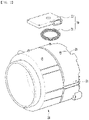
- FIG. 3 is a view briefly showing a positional relationship between the tub 20, the drum 30, and the induction module 70, omitting the cabinet 10, in the laundry treating apparatus according to an embodiment of the present disclosure.
- FIG. 3 shows that the induction module 70 is disposed on a portion of the outer circumferential surface of the tub 20 above a top surface of the drum 30, but this is only for helping understanding, and does not exclude a case in which the induction module 70 is disposed on a portion of the outer circumferential surface of the tub 20 corresponding to the side surface or the bottom portion of the drum 30.
- two or more induction modules may be arranged in the front and rear direction of the tub 20. That is, it is possible to evenly heat the outer circumferential surface of the drum 30 by arranging the plurality of the induction modules side by side in the front and rear direction on the outer circumferential surface of the tub 20.
- the laundry when an amount of laundry M is small, the laundry may be biased toward a rear portion of the drum. This is because a tilted drum is used a lot. Conversely, when the amount of laundry is large, the laundry may be evenly arranged in front and rear portions of the drum.
- the induction modules may be driven depending on a situation in a scheme of driving only the rear induction module when the amount of laundry is small and driving all induction modules when the amount of laundry is large. In one example, it will be possible to drive only one induction module as needed.
- the induction module may be disposed at a center of the drum 30. That is, when only one induction module is disposed, the induction module may be disposed in a portion corresponding to the center of the drum 30 of the outer circumferential surface of the tub 20. In other words, one induction module may be disposed in a form extending in the front and rear direction from a center in the front and rear direction of the tub 20.
- the induction module When the induction module is biased forwards, the induction module may heat a gasket disposed between the tub 20 and the drum 30 or heat a door that opens and closes the opening of the drum from the front of the drum.
- the induction module when the induction module is biased rearwards, the induction module may heat the driver 40 and the rotation shaft 42. This unnecessarily heats up other components of the laundry treating apparatus, so that not only the waste of energy is caused, but also said other components may be overheated to be deformed or to malfunction. Thus, this should be prevented.
- the driver such as the motor or the shaft 42 is disposed at the rear of the drum 30, and the rear portion of the drum is recessed forwards for the connection to the spider 43.
- the rear surface of the drum is connected to the spider, and this portion has a very small area in contact with the laundry. That is, the area in contact with the laundry is small compared to the circumferential surface of the drum. Therefore, it may be said that heating the rear surface of the drum is very disadvantageous in terms of efficiency. Therefore, in order to prevent this, the induction module may be disposed at the center without being biased forwards or rearwards.
- the plurality of induction modules may be disposed.
- the induction module may be disposed with a predetermined distance from a frontmost portion of the drum 30 and a rearmost portion of the drum 30.
- the door, a circulation duct, a spray nozzle, and the like disposed between the drum 30 and the tub 20 may be heated, and when the induction module extends to a portion corresponding to the rearmost portion of the drum 30 in the vertical direction, the driver 40 or the like of the drum 30 may be heated.
- the induction module may be disposed only in a section spaced apart by a predetermined distance from the frontmost portion and the rearmost portion of the drum 30 to prevent other components of the laundry treating apparatus from being heated as the eddy current is generated therein.
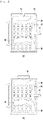
- FIG. 4 shows embodiments of a planar shape of a coil. That is, FIG. 4 shows the coil viewed from the top.
- (a) in FIG. 4 is a view showing that the coil 71 is formed in a circular shape
- (b) in FIG. 4 is a view showing that the coil 71 is formed in an oval shape
- (c) in FIG. 4 is a view showing that the coil 71 is formed in a track shape.
- the coil 71 may be wound at least once while maintaining an original shape thereof.
- the coil 71 may be formed in a flat shape, and may be formed in a shape having a curved surface on the left and right in consideration of the cylindrical outer circumferential surface of the tub 20.
- the coil 71 may be formed in the oval shape. That is, the coil 71 may be formed in an oval shape in which a long axis is formed in the front and rear direction of the tub. In this regard, as the length of B is greater than the length of A, the coil 71 is longer in the front and rear direction of the tub 20, so that the front and rear portions of the drum 30 may be evenly heated.
- the coil 71 may be formed in the track shape.
- the "track shape” may mean that, when setting the length in the front and rear direction of the tub 20 as a vertical length and setting the length in the left and right direction of the tub 20 as a horizontal direction, the coil 71 is formed in a shape including a first straight portion 7111 extending in the front and rear direction of the tub 20, that is, in the vertical direction with respect to a longitudinal axis of the tub 20, a second straight portion 7112 extending in the left and right direction of the tub 20, that is, a direction perpendicular to the first straight portion 7111, and a curved portion 712 in a curved shape for connecting the first straight portion 7111 and the second straight portion 7112 to each other.
- the "track shape” may be a rectangular shape with rounded vertices. That is, several pairs of first straight portions 7111 and several pairs of second straight portions 7112 may be disposed, and several pairs of curved portions 712 for connecting the first straight portion 7111 and the second straight portion 7112 to each other may be disposed.
- the coil 71 when the coil 71 is formed in a rectangular shape, the wire may be bent at the corners (the vertices) to cause a safety accident or the like, which may make it difficult to ensure the safety.
- the coil 71 according to an embodiment of the present disclosure is preferably formed in the track shape.
- heating efficiency and drying efficiency may vary depending on the shape of the coil.
- the heating efficiency may be referred to as an output compared to an input (a heating amount of the drum).
- the heating efficiency may be referred to as a ratio of electrical energy, which is applied to the induction module, converted to heat energy, which heats the drum.
- the drying efficiency may be referred to as an output compared to an input until the entire laundry is sufficiently dried. In the latter case, it may be said that a time factor is further considered.
- the coil is preferably positioned so as to face the center in the front and rear direction of the drum. Similarly, it may be said to be a result of considering the drying efficiency although the coil position and the varying in the heating efficiency are not relevant.
- the coil 71 is a single coil and is formed in the oval shape or the track shape having the long axis in the front and rear direction of the drum.
- the center of the coil 71 faces the center of the drum in the front and rear direction.
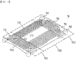
- the induction module 70 has a base housing 74 for fixing the coil 71 will be described in detail with reference to FIG. 5 .
- FIG. 5 shows the base housing 74 for which the coil is formed and the coil is fixed.
- the base housing 74 may be integrally formed through plastic injection.
- the wire may be inserted into the base housing 74 to form the coil 71. Accordingly, a gap between turns of the wire may be maintained, and the wire may be fixed. Therefore, the coil as a whole may be fixed without being deformed.
- the base housing 74 may include a base 741 that provides a space for the coil 71 to be accommodated, the module cover 72 coupled to a top surface of the base 741, a fixing rib 7421 extending upwards from the base 741, and a support rib 7422 extending downwards from the base 741.
- the induction module 70 may further include the base housing 74 that, when the coil 71 is wound at least once from the front to the rear and from the rear to the front of the tub 20 in the induction module, allows the turns of the wire to be spaced apart from each other.
- the base housing 74 may be coupled to the module cover 72. Accordingly, the base housing and the module cover 72 may be coupled to each other to define an internal space in which the coil 71 is disposed. Therefore, the base housing 74 and the module cover 72 may be referred to as a module housing.
- the base housing 74 may be coupled to the module cover 72 to be accommodated in the module cover 72.
- the base housing 74 may be disposed separately from the tub 20 to be coupled to the outer circumferential surface of the tub.
- the base housing 74 may be formed integrally with the tub 20.
- the base housing 74 is preferably formed separately from the tub.
- FIG. 5 shows a structure in which the base housing 74 may be coupled to the outer circumferential surface of the tub 20, but as described above, the case in which the base housing 74 is integrally injected with the tub 20 is not excluded.
- the base housing 74 may include the base 741 disposed on the outer circumferential surface of the tub.
- the base 741 may be formed to have a curvature or a shape corresponding to the curvature or the shape of the outer circumferential surface of the tub, and may be formed in a plate shape to be parallel to the outer circumferential surface of the tub.
- the coil 71 may be wound around the base 741. That is, the coil may be wound around the base at least once by reciprocating the tub in the front and rear direction.
- the base 741 may be referred to as a component on which a bottom surface or a lower portion of the wire is seated.
- the base 741 may include a coupling portion 743 that may be attached to and coupled to the outer surface of the tub.
- the coupling portion 743 may correspond to a module coupling portion 26 formed on the outer circumferential surface of the tub as shown in FIG. 2 .
- the two coupling portions 743 and 26 may be coupled to each other through a screw.
- the base 741 may be supported by the coupling portion 743 and may be spaced apart from the tub by a predetermined gap. This is to prevent the base 741 from being directly exposed to the vibration of the tub.
- the coupling portion 743 may be coupled through the screw or the like, it is possible to minimize the separation distance from the tub 20. Therefore, the heat generated by the coil 71 may be transferred to the drum 30 with a minimum loss.
- the base 741 may be formed in the plate shape having the same curvature as a portion of the circumferential surface of the tub 20 to which the base housing 74 is coupled. This is to uniformly heat the drum 30 by making the gap between the coil 71 and the tub 20 constant.
- a reinforcing rib for compensating for the gap between the base and the outer circumferential surface of the tub and supporting a strength of the base may be further included.
- the base 741 may be in complete surface contact with the outer circumferential surface of the tub.
- the gap between the coil 71 and the drum 30 may be narrowed as much as possible to prevent dispersion of the magnetic field.
- the base 741 may have a coil slot 742 for guiding the coil 71 to be wound at least once on one surface thereof.
- the coil slot 742 may guide the wire of the coil 71 to be wound such that the turns of the wire are spaced apart from each other by the predetermined gap.
- the coil slot 742 may be formed in the track shape. That is, the overall shape of the coil slot 742 may be the track shape.
- the fixing ribs may form a plurality of lanes within the track shape. That is, two adjacent fixing ribs may form one lane, and the wire may be inserted into the lane. The number of windings of the coil may be determined based on the number of lanes.
- the coil slot 742 may be referred to as a component to which a side surface or a side portion of the wire is in close contact. Because both side surfaces or both side portions of the wire are in close contact with the coil slots 742, a lateral movement of the wire is prevented. Accordingly, the shape of the coil may be maintained.
- the fixing rib 7421 may be formed such that the coil 71 is formed in at least one of the circular, oval, and track shapes whose size is expanded while a center thereof is shared.
- an extension line between the fixing ribs 7421 may be formed in the circular, oval, and track shapes.
- FIG. 5 shows that the coil slot 742 is formed as a combination of the fixing ribs 7421, and the fixing rib 7421 is formed in the track shape having the straight portion and the curved portion. Accordingly, the coil 71 may be disposed on the base 741 while being wound starting with an outermost fixing rib 7421 or starting with an innermost fixing rib 7421.
- the fixing rib 7421 not only guides the winding of the coil 71, but also allows the turns of the coil 71 to maintain a minimum gap from each other when the coil is wound.
- a coil accommodating portion is defined between the two adjacent fixing ribs 7421. That is, the wire of the coil 71 may be accommodated in the coil accommodating portion defined as the fixing ribs 7421 are spaced apart from each other. That is, it may be seen that the fixing ribs 7421 are spaced apart from each other to define the coil accommodating portion.
- the coil slot 742 may be formed by the combination of the coil accommodating portion and the fixing ribs 7421.
- the fixing rib 7421 may be formed to protrude upwardly of the base 741.
- a bottom surface of the accommodating portion may be referred to as a top surface of the base 741.
- the fixing rib 7421 may form the top surface of the base.
- the accommodating portion may be recessed downwards, so that the fixing rib 7421 indirectly protrudes upwardly of the accommodating portion.
- the coil 71 when describing the coil 71 in a subdivided manner, may be divided into a front coil portion 7121 adjacent to the front portion of the tub 20, a rear coil portion 7122 adjacent to the rear portion of the tub 20, and an intermediate coil portion 7123 formed between the front coil portion 7121 and the rear coil portion 7122.
- the coil 71 may be formed in the track shape.
- a portion located on the front portion of the tub 20 and a portion located on the rear portion of the tub 20 of sides including the curved portion 712 of the coil 71 may be respectively divided as the front coil portion 7121 and the rear coil portion 7122, and a portion formed between the front coil portion 7121 and the rear coil portion 7122 may be divided as the intermediate coil portion 7123.
- the shape of the coil 71 may not be limited thereto and the coil 71 may be formed in the circular or oval shape. However, as described above, it is most preferable for the coil 71 to be formed in the track shape, and thus, a description will be made based on the track shape.
- FIG. 6 is a view showing a tub according to an embodiment of the present disclosure. (a) in FIG. 6 is a front view of the tub 20, and (b) in FIG. 6 is a cross-sectional view of the tub viewed from the side.
- a safety apparatus may be a blocking assembly 80 to be described later.
- the time required for the heating is less than that of the conventional laundry treating apparatuses.
- the shorter drying or heating time may mean that the temperature of the drum 30 or the coil 71 rises quickly to that extent.
- the safety apparatus may be required to ensure the safety of the user. Because a heated portion is the drum 30 and a portion that radiates the heat is the coil 71, the safety apparatus may be disposed separately for each of the drum 30 and the coil 71.
- the safety apparatus is preferably disposed at a position capable of sensing both the heat transferred from the induction module 74 and the heat transferred from the drum 30.
- a condensate inlet 21 may be formed on the tub 20 of the laundry treating apparatus 1 according to an embodiment of the present disclosure.
- wet steam may be generated from a dry load inside the drum 30.
- the generated wet steam is condensed in a portion with a low temperature of the inner circumferential surface of the tub 20. Therefore, it is possible to accelerate the drying by introducing condensate from the rear of the tub 20 and flowing the condensate to the inner circumferential surface of the tub 20 to increase an amount of heat of condensation.
- the safety apparatus is preferably disposed above a portion of the tub 20 where the condensate inlet 21 is formed. Specifically, it is not preferable that the safety apparatus is disposed in the portion where the condensate inlet 21 is formed and a portion where the condensate flows of the tub 20. Specifically, this is because the safety apparatus may come into contact with the water to cause another safety accident such as a short circuit, which is contrary to the purpose of the safety apparatus, and it is undesirable for the safety apparatus to operate based on a temperature of a locally cooled portion as the condensate is introduced.
- the safety apparatus is preferably disposed to be adjacent to the induction module 74.
- the induction module 74 is disposed so as to cover a vicinity of the center of the tub 20 as described above. In addition, the induction module 74 is disposed to be spaced by the predetermined distance apart from the frontmost and rearmost portions of the tub 20.
- a temperature rising at the front and rear portions of the drum 30 may be lower than a temperature rising at the center of the drum 30 due to a characteristic of the winding shape of the coil 71. Therefore, it is preferable that the safety apparatus is disposed in a region that may have a high temperature.
- the safety apparatus is disposed below the intermediate coil portion 7123. This is because it may be advantageous to ensure the safety when the safety apparatus is disposed in the region that may have the high temperature.
- the safety apparatus is disposed above the condensate inlet 21 while being disposed adjacent to the region of the induction module that may have the high temperature.
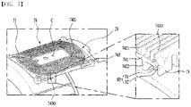
- FIG. 7 is a view showing that a blocking assembly is disposed in an induction module of a laundry treating apparatus according to an embodiment of the present disclosure.
- the treating laundry apparatus 1 may include the blocking assembly 80.
- the blocking assembly 80 blocks the current flowing in the induction module 74 to stop the heating, thereby preventing the safety accident.
- the blocking assembly 80 may include a blocking member 81 that blocks the current when heated to have a temperature equal to or higher than a preset temperature, and a tube 82 that surrounds the blocking member 81 and has elasticity.
- the blocking assembly 80 may include a plurality of blocking assemblies, and one may measure the temperature of the drum 30 and another may measure the temperature of the coil 71. However, as the number of blocking assemblies 80 increases, an increase in an amount of material and an inconvenience of repair may be caused. Therefore, when one blocking assembly 80 is disposed, the manufacturing cost may be reduced, and the blocking assembly 80 may be easily replaced without a process of identifying where the blocking assembly is operating when the blocking assembly 80 is operated.
- the temperatures of the drum 30 and the coil 71 must be simultaneously measured, so that the location and a disposition condition of the blocking assembly 80 are very important. In other words, it is important that the blocking assembly 80 is placed at an appropriate location so as not to be removed.
- the blocking member 81 may be formed in a shape of a thermostat or a thermofuse. However, it is preferable that the blocking member 81 is formed in the shape of the thermofuse.
- the thermostat has an advantage of being used reversibly and repeatedly.
- the blocking member 81 being disposed in the laundry treating apparatus 1 is to be operated after ensuring the safety by being sufficient cooled after the current is cut off to prevent the overheating.
- the tube 82 may serve to prevent damage to the blocking member 81 even when the blocking assembly 80 is compressed through a tolerance design of a space in which the blocking assembly 80 is disposed. Therefore, the tube 82 is preferably made of a material having elasticity. A detailed description thereof will be given later.
- the tube 82 may serve to assist in measuring the temperature more precisely by minimizing an amount of heat lost to the air by expanding a heat conduction area.
- the blocking member 81 may be cut off to block the current.
- the blocking member 81 may receive the heat from the coil 71 and the drum 30, and a predetermined heat dissipation may be performed to a vicinity thereof. That is, the blocking member 81 is not insulated from surroundings other than the coil 71 and the drum 30. The reason that the blocking member 81 is not insulated from the surroundings other than the coil 71 and the drum 30 may be to allow a temperature at which the blocking member 81 operates to be adjusted.
- the blocking member 81 may operate even though the coil 71 and the drum 30 have not reached dangerous temperatures because the blocking assembly 80 does not directly measure the temperature of the coil 71 or the drum 30, but is heated by the amount of heat transferred from the coil 71 or the drum 30.
- the blocking member 81 when, as the amount of heat transferred becomes greater than the amount of heat dissipation, the blocking member 81 is continuously heated to have a temperature equal to or higher than the preset temperature, the blocking member 81 may be cut off to block the current provided to the induction module 74.
- an overall heat transfer coefficient in a heat transfer path from the coil 71 to the blocking assembly 80 and an overall heat transfer coefficient in a heat transfer path from the drum 30 to the blocking assembly 80 may be different.
- the dangerous temperatures of the coil 71 and the drum 30 may be different.
- the dangerous temperature of the coil may be about 120 °C
- the dangerous temperature of the drum 30 may be about 150 °C.
- the base housing 74 may include the support rib 7422 as described above.
- the support rib 7422 may be a portion extending downwardly of the base 741 and in contact with the tub 20.
- a plurality of support ribs 7422 may be disposed. Because the plurality of support ribs 7422 are disposed, the base housing 74 may be stably supported on the circumferential surface of the tub 20.
- At least one of the support ribs 7422 may be disposed to be biased on both sides in the left and right direction of the base 741.
- the support rib 7422 may be disposed so as to be biased on both sides of the base 741 in a direction perpendicular to the longitudinal axis of the drum.
- the blocking assembly 80 may be disposed between two support ribs 7422 disposed to be biased on the both sides in the left and right direction.
- the blocking assembly 80 may be disposed between the base 741 and the tub 20 to sense both the heat transferred from the coil 71 and the heat transferred from the drum 30.
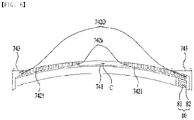
- FIGS. 8 and 9 are cross-sectional views of a base housing of an induction module of a laundry treating apparatus according to an embodiment of the present disclosure.
- the base housing 74 may include the base 741, the fixing rib 7421, and the support rib 7422.
- the base 741 may be formed in the shape of the plate having the curvature the same as the curvature of the circumferential surface of the tub 20. It is possible to provide the space for accommodating the coil 71 formed by winding the wire on the base 741.
- the fixing rib 7421 may define the coil slot 742 as the portion extending upwards from the base 741.
- the plurality of fixing ribs 7421 may be formed to have a predetermined gap such that the turns of the wire have the predetermined gap when the coil 71 is wound.
- the coil slot 742 may include an innermost coil slot 742i defined closest to a center C of the base 741 and an outermost coil slot 742o defined farthest from the center C of the base 741.
- the blocking member 81 is disposed at a position spaced apart from a bottom of the innermost coil slot 742i leftwards or rightwards. This is to prevent the blocking member 81 itself from being overheated by the overheating of the coil 71 while the blocking member 81 simultaneously senses whether the tub 20 and the coil 71 are overheated.
- the blocking member 81 is preferably located below the outermost coil slot 742o.
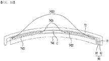
- the blocking member 81 may be disposed at a position spaced apart from a bottom of the outermost coil slot 742o in a direction away from the lower portion of (see FIG. 10 ). In this case, the blocking member 81 may be located between an outermost support rib 75, which will be described later, and the base 741.
- the support rib 7422 which is a portion extending from the base 741 in a direction opposite to the fixing rib 7421, may be a portion in contact with the tub 20 to define the space for the blocking assembly 80 to be accommodated.
- the support rib 7422 which is a portion extending from the base 741 in a direction opposite to the fixing rib 7421, may be a portion in contact with the tub 20 to define the space for the blocking assembly 80 to be accommodated.
- the support rib 7422 may be disposed so as to be biased on the both sides of the base 741, specifically, the both sides in the direction perpendicular to the longitudinal axis of the drum. This may be because the heat may be transferred from the coil 71 and the drum 30 to the blocking assembly 80 without significant loss because the both sides of the base 741 are more easily compressed as the coupling portion 743 is screw-coupled.
- the base 741 and the tub 20 are not necessarily coupled to each other only through the screw coupling. Depending on a degree of coupling, it is sufficient when the base 741 may be in close contact with the tub 20 as much as possible, and it is sufficient when the base 741 and the tub 20 are coupled to each other at a degree at which the blocking assembly 80 may be sufficiently pressurized.
- the support rib 7422 that provides the space for the blocking assembly 80 to be accommodated may be biased to the both sides of the base 741 such that the blocking assembly 80 is disposed far from the center of the base 741.
- the support rib 7422 may include the outermost support rib 75 extending downwards from an end of one of the left and right sides of the base 741.
- the present disclosure may not be limited thereto, and the outermost support rib 75 may be formed to extend downwardly of the base 741 from an end of at least one of left and right sides of the module cover 72, as will be described later. That is, the outermost support rib 75 may be formed to extend downwardly from the base 741, or may be formed to extend downwardly from the module cover 72.
- the blocking assembly 80 may be accommodated between the support rib 7422 and the outermost support rib 75.
- the support rib 7422 and the outermost support rib 75 may have a gap therebetween equal to a diameter or a length in the left and right direction of the tube 82, or may have a gap such that the tube 82 is press-fitted into the space between the support rib 7422 and the outermost support rib 75. Accordingly, the tube 82 may be disposed to be pressed between the support rib 7422 and the outermost support rib 75.
- the blocking assembly 80 may be fixed without shaking in the left and right direction even when a force is applied to the treating apparatus 1.
- the blocking assembly 80 receives forces from both of the support rib 7422 and the outermost support rib 75, even when a force is applied in an upward direction, the blocking assembly 80 may not be deviated upwards by a shear stress.
- the blocking assembly 80 may be compressed in the left and right direction as well as compressed in the vertical direction.
- the blocking assembly 80 may be disposed beneath the base 741 and on top of the top surface of the tub 20 as described above.
- the base 741 and the tub 20 may be spaced apart from each other by the same length as the vertical length of the blocking assembly 80 or by a length at which the blocking assembly 80 may be press-fitted.
- the blocking assembly 80 may sense the overheating of the drum and the coil stably at an original position thereof without being removed.
- the blocking assembly 80 may be disposed to be pressed between the base 741 and the tub 20.
- the separation distance may be adjusted by the screw coupling of the coupling portion 743. This is because, as the blocking assembly 80 is disposed so as to be biased to one of the left and right sides of the base 741 and the both sides of the base 741 are firmly fixed to the top surface of the tub 20 by the screw coupling of the coupling portion 743, the blocking assembly 80 may be coupled to the bottom surface of the base 741 and the top surface of the tub 20 so as to be more strongly in contact therewith based on the rotation of the screw.
- the blocking assembly 80 may be pressed in the vertical direction between the base 741 and the tub, and pressed in the left and right direction between the support rib 7422 and the outermost support rib 75. Accordingly, the blocking assembly 80 may effectively receive the heat transferred from the coil 71 and the drum, and may not deviate from the original position thereof even under the external impact, thereby guaranteeing reliability of the laundry treating apparatus.
- the fixing rib 7421 may be formed to extend upwardly of the base 741 and extend from a distal end thereof in the left and right direction.
- a height of the portion of the fixing rib 7421 extending in the left and right direction may be a height the same as or close to the diameter of the wire forming the coil 71 to press the wire.
- the heat of the coil 71 may be effectively transferred to the base 741, thereby ensuring reliability of the blocking assembly 80.
- the blocking assembly 80 may receive the heat by at least two turns of the wire. This may be for compensating for the difference between the heat transfer path from the drum 30 and the heat transfer path from the coil 71.
- the heat transfer path from the drum 30 the heat emitted from the drum 30 is convected through the space between the drum 30 and the tub 20, and is conducted through the tub 20 to be transferred to the blocking assembly 80.
- the coil 71 conducts the heat through the base 741 and transfers the heat to the blocking assembly 80.
- the present disclosure is not limited to the above-described paths, and it is sufficient when the heat transfer path from the drum 30 and the heat transfer path from the coil 71 are different.
- the blocking assembly 80 receives the heat from the top surface of the tub 20 by an area of the blocking assembly 80, and receives the heat from the bottom surface of the base 741 by the area of the blocking assembly 80.
- the area of the blocking assembly 80 may not be an area corresponding to one turn of the wire, but may be an area for receiving the heat generated from several turns of the wire.
- FIG. 11 is an exploded perspective view of a tub and an induction module of a laundry treating apparatus according to another embodiment of the present disclosure.
- the induction module 74 included in the laundry treating apparatus 1 may include the module cover 72, and the module cover 72 may have a coil cooler 76 formed thereon.
- the coil cooler 76 may be formed at a center of the module cover 72.
- the coil cooler 76 may include a fan housing 763 coupled to the module cover 72 and a fan 761 disposed in the fan housing 763 to form an airflow.
- Air may be introduced into the module cover 72, that is, into the induction module through the coil cooler. Because the space is defined between the module cover 72 and the base 741 inside the induction module, an air flow space is defined. In addition, a penetrated portion (not shown) may be defined in the base 741. Accordingly, the air may cool the coil 71 in the internal space and may be discharged to the outside of the induction module 74 through the penetrated portion of the base 741.
- the blocking assembly 80 which is a structure that prevents the overheating of the coil 71 and the drum 30 and prevents the overheating of the base 741, is preferably disposed as far from the coil cooler 76 as possible.
- the blocking assembly 80 senses the temperatures of the drum 30 and the coil 71 and is cut off when the blocking member 81 is heated to have the temperature equal to or higher than the preset temperature to block the power supplied to the induction module 74. This is because the blocking member 81 may not operate by the fan 761 disposed in the coil cooler 76. That is, when the blocking assembly 80 is positioned adjacent to a portion locally cooled by the cooling fan, even when another portion of the coil 71 is heated to the dangerous temperature, the blocking member 81 may not be able to sense the same.
- the blocking assembly 80 is preferably disposed so as to be spaced apart as far as possible from the coil cooler 76. Accordingly, the blocking assembly 80 is preferably located in the intermediate coil portion 7123, which is the region that may have the high temperature while sufficiently spaced apart from the coil cooler 76, in order to minimize the effect of the coil cooler 76.
- the blocking assembly 80 is preferably disposed at a position spaced apart from a center of rotation of the fan 761.
- the blocking assembly 80 is preferably disposed at a position spaced apart from the fan housing 763.
- the blocking assembly 80 is preferably disposed at a position spaced apart from the fan housing 763 leftwards or rightwards.
Landscapes
- Physics & Mathematics (AREA)
- Electromagnetism (AREA)
- Engineering & Computer Science (AREA)
- Textile Engineering (AREA)
- Detail Structures Of Washing Machines And Dryers (AREA)
- Main Body Construction Of Washing Machines And Laundry Dryers (AREA)
Abstract
Description
- The present disclosure relates to a laundry treating apparatus.
- A laundry treating apparatus includes a washing machine or a dryer. The washing machine is an apparatus that washes clothes, bedding, and the like (hereinafter, a 'laundry') through processes such as washing, rinsing, dehydration, and the like to remove contamination from the laundry using water, detergent, and a mechanical action, and the dryer is an apparatus for drying clothes that have been washed or wet clothes (hereinafter, the 'laundry') by exposing the laundry to a high temperature.
- In general, the washing machine needs to increase a temperature of the laundry in order to increase a washing efficiency of the laundry. In addition, the washing machine needs to increase the temperature of the laundry for sterilization of the laundry.
- To this end, the washing machine increased the temperature of the laundry by receiving hot water directly from an external water supply source, or increased the temperature of the laundry indirectly by having a separate heater to heat washing water in which the laundry is immersed.
- That is, the conventional washing machine had to supply the washing water to a vertical level at which all the laundry is submerged and had to also heat the washing water in order to increase the temperature of the laundry. This resulted in unnecessary waste of material and energy.
- In general, the dryer performed a drying cycle by heating air with the heater and exposing the heated air to the laundry to evaporate moisture contained in the laundry.
- In this regard, a phenomenon in which the hot air does not evenly contact the laundry occurred frequently. In particular, when there is a large amount of laundry or the laundry is aggregated, there was a problem in that a drying efficiency is lowered because the hot air is not evenly supplied throughout the laundry.
- In addition, in the process of supplying the hot air to completely dry a portion of the laundry that is not dried, there was a problem in that the hot air is continuously supplied to a portion where the drying was completed, and the laundry is damaged.
- For this reason, a laundry treating apparatus equipped with an induction module for directly heating a drum in a tub has emerged.
- The induction module is disposed on an outer circumferential surface of the tub to heat the drum. When the drum is directly heated, a drying function may be increased by increasing the temperature of the air passing through the drum without unnecessary heating of the washing water. In addition, when the induction module is disposed, a time required for the heating may be saved because the drum is directly heated without heating the washing water. Therefore, the laundry treating apparatus including the induction module may increase energy efficiency by preventing the unnecessary energy waste compared to the conventional washing machine, and shorten a washing time, so that a user may wash the laundry conveniently. In addition, because the laundry treating apparatus including the induction module may exert sufficient washing effect even with a small amount of energy, the washing efficiency may be increased, thereby increasing user satisfaction. In the laundry treating apparatus, the drum is rapidly heated by the induction module, so that there is a risk of a safety accident. Therefore, a need for a safety device to prevent such accident and to secure product reliability is increasing.
- According to an embodiment of the present disclosure, it is to provide a laundry treating apparatus that may reduce a time required for washing.
- In addition, it is to provide a laundry treating apparatus that may guarantee a drying effect while reducing a time required for washing.
- In addition, it is to provide a laundry treating apparatus that ensures safety by measuring an accurate temperature when a drum or a coil is overheated while having a short washing time and excellent drying effect.
- More specifically, it is to provide a laundry treating apparatus in which a component for blocking power supplied to the laundry treating apparatus may be stably disposed at an appropriate position when a temperature is equal to or higher than a predetermined temperature.
- In addition, it is to provide a laundry treating apparatus that may save a manufacturing cost as much as possible in order to ensure safety.
- In addition, it is to provide a laundry treating apparatus that is easy to repair and replace parts even when an electric current is cut off for safety. In addition, it is to provide a laundry treating apparatus that guarantees safety against external impact.
- According to one embodiment of the present disclosure, provided is a laundry treating apparatus including an induction heater module and a safety apparatus for preventing overheating of a drum.
- In addition, provided is a laundry treating apparatus in which the safety apparatus is formed in a shape of a fuse.
- In addition, provided is a laundry treating apparatus in which one blocking assembly, which is the safety apparatus, simultaneously contacts a coil base and a tub to prevent overheating of a coil or the drum.
- In addition, provided is a laundry treating apparatus in which the blocking assembly is disposed so as to be fixed to a bottom of the coil and the tub by being pressed and deformed.
- In addition, provided is a laundry treating apparatus in which the blocking assembly is located in a region adjacent to the coil base and a region adjacent to a center of the drum in an axial direction, that is, a region that may have a high temperature.
- In addition, provided is a laundry treating apparatus in which the blocking assembly is disposed at a location where an influence of a cooling fan is small in consideration of interference with tub surroundings.
- Provided is a laundry treating apparatus including a tub, a drum accommodating laundry therein and made of a metal material, and an induction module disposed on an outer surface of the tub and generating an electromagnetic field to heat a circumferential surface of the drum, wherein the induction module includes a coil formed by winding a wire applied with a current, wherein the coil generates a magnetic field, a base housing mounted on an outer circumferential surface of the tub to accommodate the coil therein, and a blocking member disposed to be simultaneously in contact with the base housing and the tub to block the current when being heated to a temperature equal to or higher than a preset temperature by at least one of an amount of heat transferred from the coil and an amount of heat transferred from the drum.
- In addition, provided is a laundry treating apparatus including a tube surrounding the blocking member and having elasticity, wherein the base housing includes a base for supporting the coil, a fixing rib extending from the base to define a coil slot for the coil to be accommodated, and a support rib extending downwardly of the base to provide a space for accommodating the blocking assembly therein, wherein the blocking member is pressed in contact with the base and the tub, and the tub includes an induction module coupling portion formed on an outer circumferential surface thereof, wherein the base includes a coupling portion coupled to the outer surface of the tub, and the base is formed in a plate shape having the same curvature as the outer circumferential surface of the tub.
- In addition, provided is a laundry treating apparatus in which the blocking member is a thermofuse.
- In addition, provided is a laundry treating apparatus further including a module cover coupled to the base, wherein at least one of the module cover and the support rib includes an outermost support rib extending downwardly from an end thereof, wherein the blocking member is disposed to be pressed between the outermost support rib and the support rib, wherein the support rib is disposed to be biased on both sides of the base in a direction perpendicular to a longitudinal axis of the drum.
- In addition, provided is a laundry treating apparatus in which the base housing further includes a module cover coupled to the base, wherein a coil cooler for cooling the coil is coupled to the module cover and the coil cooler is coupled to a center of the module cover, wherein the blocking member is disposed to be spaced apart from the coil cooler by a predetermined distance.
- In addition, provided is a laundry treating apparatus in which the coil includes a pair of straight portions extending in a longitudinal direction of the tub and a curved portion for connecting the straight portions to each other, wherein the coil includes a front coil portion including the curved portion disposed adjacent to a front portion of the tub, an intermediate coil portion including the straight portion, and a rear coil portion including the curved portion disposed adjacent to a rear portion of the tub, wherein the blocking member is disposed below a portion of the base housing where the intermediate coil portion is located, wherein the blocking assembly receives heat by at least two turns of the wire.
- In addition, provided is a laundry treating apparatus in which one blocking member is disposed.
- In order to achieve the above purpose, an embodiment of the present disclosure may provide a laundry treating apparatus including a cabinet, a tub disposed inside the cabinet and accommodating washing water therein, a drum rotatably disposed inside the tub to accommodate laundry therein, wherein the drum is made of a metal material, and an induction module spaced apart from the drum and heating the drum by generating an electromagnetic field, wherein the induction module includes a coil formed by winding a wire applied with a current, wherein the coil generates a magnetic field, a base housing mounted on an outer circumferential surface of the tub to accommodate the coil therein, and a blocking member disposed between the base housing and the tub to selectively block the current applied to the coil.
- The blocking member may block the current applied to the coil when at least one of the tub, the coil, and the base housing is heated to have a temperature equal to or higher than a preset temperature.
- The base housing may include a base for providing a space for accommodating the coil therein, a fixing rib extending from the base in a direction away from the tub to define a coil slot for the coil to be wound, and a support rib extending from the base toward the tub to define a separation space between the base and the tub, and the blocking member may be located in the separation space.
- The coil slot may include an innermost coil slot defined closest to a center of the base among the coil slots, and an outermost coil slot defined farthest from the center of the base among the coil slots, and the blocking member may be disposed at a position spaced apart from a bottom of the innermost coil slot in a left direction or a right direction.
- The blocking member may be located below the outermost coil slot.
- The blocking member may be disposed at a position spaced apart from a bottom of the outermost coil slot in a direction away from the innermost coil slot.
- The induction module may further include a tube for surrounding the blocking member and in contact with each of the base and the tub.
- The tube may be made of an elastic material and may be press-fitted and fixed to the base and the support rib.
- The base housing may be disposed above the tub.
- The base housing may further include a module cover coupled to a top surface of the base to cover the coil, at least one of the module cover and the support rib may include an outermost support rib extending toward the tub from at least one of both ends thereof in a left and right direction, and the tube may be press-fitted and fixed between the outermost support rib and the support rib.
- In order to achieve the above purpose, an embodiment of the present disclosure may provide a laundry treating apparatus including a cabinet, a tub disposed inside the cabinet and accommodating washing water therein, a drum rotatably disposed inside the tub to accommodate laundry therein, wherein the drum is made of a metal material, and an induction module spaced apart from the drum and heating the drum by generating an electromagnetic field, wherein the induction module includes a coil formed by winding a wire applied with a current, wherein the coil generates a magnetic field, a base housing mounted on an outer circumferential surface of the tub to accommodate the coil therein, and a blocking member for selectively blocking the current applied to the coil, wherein the coil includes a pair of straight portions extending in a front and rear direction and a curved portion connecting the straight portions to each other and located above the tub and corresponding to a front portion or a rear portion of the tub, wherein the blocking member is located below the straight portion.
- The blocking member may be disposed between the base housing and the tub.
- The blocking member may be disposed at a position spaced apart from the curved portion in the front and rear direction.
- The base housing may be disposed above the tub.
- The base housing may includes a base for providing a space in which the coil is accommodated, and a module cover coupled to the base to cover the coil, and a coil cooler for forming an airflow to cool the coil may be formed on the module cover.
- The coil cooler may include a fan housing coupled to the module cover and a fan positioned in the fan housing to form the airflow, and the blocking member may be spaced apart from a center of rotation of the fan.
- The blocking member may be spaced apart from the fan housing.
- The blocking member may be spaced apart from the fan housing in a left or right direction.
- A center of the fan housing and a center of the fan may coincide.
- The tub may include a module coupling portion formed on an outer circumferential surface of the tub, and the base housing may include a coupling portion fastened to and fixed to the module coupling portion.
- The blocking member may be a thermofuse.
- One blocking member may be disposed.
- The laundry treating apparatus according to an embodiment of the present disclosure may reduce the time required for the washing by directly heating the drum.
- In addition, the safety may be guaranteed while heating the drum quickly.
- In addition, market competitiveness may be secured by reducing the manufacturing cost for preventing the overheating of the coil and the drum.
- In addition, the overheating of the coil and the drum may be effectively sensed.
- In addition, the component that senses the overheating of the coil and the drum may be stably installed so as not to be removed.
- In addition, the safety may be guaranteed even when the external impact is applied.
-
-
FIG. 1 shows a laundry treating apparatus according to an embodiment of the present disclosure. -
FIG. 2 is an exploded perspective view of a tub and an induction module of a laundry treating apparatus according to an embodiment of the present disclosure. -
FIG. 3 is a view briefly showing a positional relationship between a tub, a drum, and an induction module, omitting a cabinet, in a laundry treating apparatus of an embodiment of the present disclosure. -
FIG. 4 is a view showing several embodiments of a coil of a laundry treating apparatus according to an embodiment of the present disclosure. -
FIG. 5 is a view showing a base housing of a laundry treating apparatus according to an embodiment of the present disclosure. -
FIG. 6 is a view showing a tub according to an embodiment of the present disclosure. -
FIG. 7 is a view showing that a blocking assembly is disposed in an induction module of a laundry treating apparatus according to an embodiment of the present disclosure. -
FIGS. 8 and9 are cross-sectional views of a base housing of an induction module of a laundry treating apparatus according to an embodiment of the present disclosure. -
FIG. 10 is an enlarged view of an induction module and a blocking assembly of a laundry treating apparatus according to an embodiment of the present disclosure. -
FIG. 11 is an exploded perspective view of a tub and an induction module of a laundry treating apparatus according to another embodiment of the present disclosure. - Hereinafter, a specific embodiment of the present disclosure will be described with reference to the drawings. A following detailed description is provided to provide a comprehensive understanding of a method, an apparatus, and/or a system described herein. However, this is only an example and the present disclosure is not limited thereto.
- In describing embodiments of the present disclosure, when it is determined that a detailed description of the known technology related to the present disclosure may unnecessarily obscure the gist of the present disclosure, the detailed description thereof will be omitted. In addition, the terms to be described later are terms defined in consideration of functions in the present disclosure, which may vary depending on intentions, customs, or the like of users and operators. Therefore, the definition thereof should be made based on the content throughout this specification. The terminology used in the detailed description is for the purpose of describing embodiments of the present disclosure only, and should in no way be limiting. Unless explicitly used otherwise, expressions in the singular include the meaning of the plural. In this description, expressions such as "comprising" or "including" are intended to indicate certain features, numbers, steps, operations, elements, and some or combinations thereof, and should not be construed to exclude a presence or a possibility of one or more other features, numbers, steps, operations, elements, or any or some or combinations thereof other than those described.
- As shown in
FIG. 1 , a laundry treating apparatus according to an embodiment of the present disclosure may include acabinet 10 for forming an appearance thereof, atub 20, adrum 30, and aninduction module 70 for heating thedrum 30. - The
tub 20 may be disposed inside thecabinet 10 to accommodate the drum therein. An opening may be defined in a front surface of the tub. Thedrum 30 is rotatably disposed inside the tub and accommodates laundry therein. Likewise, an opening may be defined in a front surface of the drum. The laundry may be put into the drum through the openings of the tub and the drum. - The
induction module 70 may heat the drum by generating an electromagnetic field. Theinduction module 70 may be disposed on an outer circumferential surface of thetub 20. Thetub 20 that provides an accommodation space therein and has the opening defined in the front surface thereof, thedrum 30, which is made of a conductor, that is rotatably disposed in the accommodation space and accommodates the laundry therein, and the induction module disposed on the outer circumferential surface of thetub 20 to heat thedrum 30 with the electromagnetic field may be included. - The
tub 20 and thedrum 30 may be formed in a cylindrical shape. Accordingly, inner circumferential surfaces and outer circumferential surfaces of thetub 20 and thedrum 30 may be formed in a substantially cylindrical shape. -
FIG. 1 shows a laundry treating apparatus in which thedrum 30 is rotated with respect to a rotation axis parallel to the ground. - The laundry treating apparatus may further include a
driver 40 for rotating thedrum 30 inside thetub 20. Thedriver 40 includes amotor 41, and the motor includes a stator and a rotor. The rotor may be connected to arotation shaft 42, and therotation shaft 42 may be connected to thedrum 30 to rotate thedrum 30 inside thetub 20. In addition, the drivingunit 40 may include aspider 43. Thespider 43, which is a component for connecting thedrum 30 and therotation shaft 42 to each other, may be referred to as a component for uniformly and stably transmitting a rotational force of therotation shaft 42 to thedrum 30. - The
spider 43 is coupled to thedrum 30 in a form of being at least partially inserted into a rear wall of thedrum 30. For this purpose, the rear wall of thedrum 30 is formed in a shape recessed into the drum. In addition, thespider 43 may be coupled in a shape of being further inserted into thedrum 30 at a center of rotation of thedrum 30. Therefore, the laundry is not accommodated at a rear end of thedrum 30 due to thespider 43. - A lifter 50 may be disposed inside the
drum 30. A plurality of lifters 50 may be disposed along a circumferential direction of the drum. The lifter 50 performs a function of stirring the laundry. For example, as the drum rotates, the lifter raises the laundry upwards. The laundry moved upwards is separated from the lifter by gravity and falls downwards. Washing may be performed by an impact force caused by such falling of the laundry. In one example, the stirring of the laundry may improve a drying efficiency. - The laundry may be evenly distributed in a front and rear direction inside the drum. Therefore, the lifter may be formed extending from the rear end to a front end of the drum. The induction module is an apparatus for heating the
drum 30. - As shown in
FIG. 2 , theinduction module 70 may include acoil 71 capable of generating a magnetic field by receiving a current to generate an eddy current in the drum, and amodule cover 72 for accommodating thecoil 71 therein. - Specifically, the
module cover 72 may be formed in a shape of a box with one surface open. That is, themodule cover 72 may be formed in a shape of a box in which a surface facing the drum is opened and a surface opposite thereto is closed. Accordingly, thecoil 71 is positioned inside themodule cover 72 or themodule cover 72 covers a top of thecoil 71. The module cover 72 functions to protect thecoil 71 from the outside. In addition, as will be described later, themodule cover 72 defines an air flow space between themodule cover 72 and thecoil 71 to cool thecoil 71. - However, the shape of the
module cover 72 is not limited to the box shape with one surface open. As will be described later, themodule cover 72 may be formed in a shape including abase 741. - In the laundry treating apparatus, the
coil 71 may heat thedrum 30 to increase an internal temperature of thedrum 30 as well as a temperature of thedrum 30 itself. Therefore, washing water in contact with thedrum 30 may be heated through the heating of thedrum 30 and the laundry in contact with the inner circumferential surface of thedrum 30 may be heated. In one example, the laundry that does not come into contact with the inner circumferential surface of thedrum 30 may also be heated by raising the internal temperature of the drum. Therefore, it is possible to increase the temperatures of the washing water and the laundry and an ambient temperature of the interior of the drum to enhance a washing effect, as well as, increase the temperatures of the laundry and the drum and the ambient temperature of the interior of the drum for drying the laundry. - Hereinafter, a principle of heating the
drum 30 by theinduction module 70 including thecoil 71 will be described as follows. - A wire is wound to form the
coil 71, and thus, thecoil 71 has a center. When a current is supplied to the wire, the current flows while rotating around the center of thecoil 71 because of the shape of thecoil 71. Accordingly, a magnetic field in a vertical direction passing through the center of thecoil 71 is generated. In this regard, when an AC current having a varying phase difference passes through thecoil 71, an AC magnetic field whose direction changes with time is formed. The AC magnetic field generates an induced magnetic field whose direction is opposite to that of the AC magnetic field in an adjacent conductor, and a change in the induced magnetic field generates an induced current in the conductor. - The induced current and the induced magnetic field may be understood as a form of inertia with respect to changes in electric and magnetic fields.
- That is, when the
drum 30 is the conductor, the eddy current or a vortex current, which is a kind of the induced current, is generated in thedrum 30 by the induced magnetic field generated by thecoil 71. - In this regard, the eddy current is dissipated and converted into heat by a resistance of the conductor of the
drum 30. That is, as a result, thedrum 30 is heated by the heat generated by the resistance, and the internal temperature of thedrum 30 is increased as thedrum 30 is heated. - In other words, when the
drum 30 is a conductor made of a magnetic material such as iron (Fe), thedrum 30 may be heated by the AC current of thecoil 71 disposed on thetub 20. - Recently, stainless steel drums have been widely used to improve strength and hygiene. Because the stainless material has relatively good electrical conductivity, it may be easily heated by the change in the electromagnetic field. This means that there is no need to specially manufacture a drum of a new shape or material to heat the drum through the
induction module 70. Accordingly, a drum used in a conventional laundry treating apparatus, that is, a drum in a laundry treating apparatus in a form of a heat pump or in a laundry treating apparatus using an electric heater (a sheath heater), may be used as it is in the laundry treating apparatus to which the induction module is applied. - The induction module including the
coil 71 and themodule cover 72 may be disposed on the inner circumferential surface of thetub 20. The magnetic field decreases in a strength with a distance, so that the induction module may be advantageously disposed on the inner circumferential surface of thetub 20 to narrow a distance from thedrum 30. - However, because the
tub 20 accommodates the washing water therein, and vibration occurs as thedrum 30 rotates, it is preferable that the induction module is disposed on the outer circumferential surface of thetub 20 for safety. This is because an interior of the tub is a very humid environment, which may be undesirable for insulation and stability of the coil. Accordingly, theinduction module 70 is preferably disposed on the outer circumferential surface of thetub 20 as shown inFIGS. 1 and2 . - In general, in the laundry treating apparatus rotates, the
drum 30 washes or dries the clothes (hereinafter, the "laundry") while rotating, so that thetub 20 is formed in the cylindrical shape. In this regard, thecoil 71 may be wound around the entire outer circumferential surface of thetub 20 at least once. - However, when the
coil 71 is wound along an entire circumference of thetub 20, not only thecoil 71 is required too much, but also the washing water leaked from thetub 20 comes into contact with thecoil 71, so that an accident such as a short circuit or the like may occur. - In addition, when the
coil 71 is wound along the entire circumference of thetub 20, the induced magnetic field is generated in the opening 22 of thetub 20 and thedriver 40, so that it may not be possible to directly heat the outer circumferential surface of thedrum 30. Accordingly, thecoil 71 is disposed on the outer circumferential surface of thetub 20, and is preferably disposed on only one side of the outer circumferential surface of thetub 20. - That is, the
coil 71 may not be wound around the entire outer circumferential surface of thetub 20, but may be wound at least once in a predetermined area in a front and rear direction of thetub 20. It may be said that an efficiency of a heat output of thedrum 30 compared to an output of theinduction module 70 is considered. In addition, it may be said that a manufacturing efficiency of the entire laundry treating apparatus is considered in consideration of a space between thetub 20 and thecabinet 10. - In addition, the
coil 71 is preferably formed in a single layer. That is, it is preferable that the wire is wound in the single layer rather than being wound in a plurality of layers. When the wire is wound in the plurality of layers, a gap is inevitably generated between two layers of the wire. Accordingly, a distance equal to the gap is inevitably generated between a wire of a bottom layer and a wire of an upper layer of the bottom layer. Therefore, a distance between the coil and the drum has to be increased at the upper layer of the bottom layer of the coil. In one example, even when such a gap may be physically excluded, the distance between the coil and the drum increases as a layer of the coil becomes higher, so that the efficiency inevitably decreases. Accordingly, it is highly desirable that thecoil 71 is formed in the single layer. This also means that a coil area in contact with the drum may be increased as much as possible while using the same length of wire. - The induction module may be disposed on one side of the outer circumferential surface of the tub, and the
coil 71 may be wound at least once along a surface of the induction module adjacent to thetub 20 within the induction module. - Accordingly, the induction module may generate the eddy current in the
drum 30 by emitting the induced magnetic field directly to the outer circumferential surface of thedrum 30. As a result, the induction module may directly heat the outer circumferential surface of thedrum 30. - Although not shown, the induction module may be connected to an external power source through an electric wire to receive power, or may be connected to a controller for controlling an operation of the laundry treating apparatus to receive the power. In addition, a module controller for controlling the output of the induction module may be disposed separately. Accordingly, the module controller may control on/off and the output of the induction module under the control of the controller.
- That is, when it is possible to supply the power to the
internal coil 71, the induction module may receive the power from anywhere. - When the power is supplied to the induction module and the AC current flows through the
coil 71 disposed inside the induction module, thedrum 30 is heated. In this regard, when thedrum 30 does not rotate, only one surface of thedrum 30 is heated, so that said one surface may be overheated and remaining surfaces of thedrum 30 may not be heated or may be heated with a small degree. In addition, the heat may not be smoothly supplied to the laundry accommodated inside thedrum 30. Accordingly, when the induction module is operated, thedriver 40 may rotate to rotate thedrum 30. - When all of the outer circumferential surfaces of the
drum 30 may face the induction module, a speed at which thedriver 40 rotates thedrum 30 may be any speed. As thedrum 30 rotates, all surfaces of thedrum 30 may be heated, and the laundry inside thedrum 30 may be evenly exposed to the heat. - Accordingly, the laundry treating apparatus according to an embodiment of the present disclosure may evenly heat the outer circumferential surface of the
drum 30 even when the induction module is installed in one place without being installed in places such as an upper portion, a lower portion, and both side portions of the outer circumferential surface of thetub 20. - In the laundry treating apparatus according to an embodiment of the present disclosure, the drum may be heated to have the temperature equal to or higher than 120 degrees Celsius within a very short time by the driving of the
induction module 70. When theinduction module 70 is driven while the drum is stopped or rotates at a very low speed, a certain portion of the drum may overheat very quickly. This is because heat transfer from the heated drum to the laundry is not sufficiently performed. - Therefore, a correlation between the rotational speed of the drum and the driving of the
induction module 70 is very important. In addition, it may be said that it is more preferable to rotate the drum and then drive the induction module than to drive the induction module and then rotate the drum. - Through the description of the above-described embodiment, it may be seen that the washing water may be saved because the laundry does not need to be completely submerged in the washing water for soaking of the laundry in the laundry treating apparatus according to an embodiment of the present disclosure. This is because a portion of the drum that comes into contact with the washing water continuously changes as the drum rotates. That is, this is because the heated portion comes into contact with the washing water to heat the washing water, and then is separated from the washing water and heated again.
- In addition, through the description of the above-described embodiment, it may be seen that, in the laundry treating apparatus according to an embodiment of the present disclosure, temperatures of the laundry and the internal space in which the laundry is accommodated may be increased. In other words, this is because the drum in contact with the laundry is heated. Thus, the laundry may be heated effectively without being submerged in the washing water. For example, the washing water may be saved because the laundry does not need to be submerged in the washing water for the sterilization. This is because the laundry may receive the heat through the drum rather than through the washing water. In addition, the interior of the drum may be changed to a hot and humid environment through steam or water vapor generated as the wet laundry is heated, so that the sterilization may be performed more effectively. Therefore, boiling washing in which the laundry is washed by being immersed in the heated washing water may be replaced by a method that uses a much smaller amount of washing water. In other words, there is no need to heat the washing water with high specific heat, so that the energy may be saved.
- In addition, through the description of the above-described embodiment, it may be seen that the laundry treating apparatus according to an embodiment of the present disclosure may reduce an amount of washing water supplied to increase the temperature of the laundry, and thus, may reduce a supply time of the washing water. This is because it is possible to reduce an amount and a time to additionally supply the washing water after the laundry soaking. Therefore, a washing time may be further reduced. In this regard, a water level of the washing water containing detergent may be lower than the lowest water level of the drum. In this case, less washing water may be used more effectively by supplying the washing water inside the tub into the drum through a circulation pump.
- Further, through the description of the above-described embodiment, it may be seen that the laundry treating apparatus according to an embodiment of the present disclosure may omit a heater that is disposed at a lower portion of the tub to heat the washing water, thereby simplifying a configuration thereof and increasing a volume of the tub.
- In particular, it may be seen that there is a limit in increasing a heating surface area of a general heater inside the tub. That is, an area in contact with the air or the laundry of a surface area of the heater is relatively small. However, on the contrary, a surface area of the drum itself or a surface area of the circumferential surface of the drum itself is very large. Accordingly, because a heating area is increased, an immediate heating effect may be obtained.
- In a conventional heating mechanism through the tub heater during the washing, the tub heater heats the washing water, and the heated washing water increases the temperatures of the drum and the laundry and the ambient temperature of the interior of the drum. Therefore, it takes a lot of time until the components are heated to a high temperature as a whole.
- However, as described above, the circumferential surface of the drum itself has a very large area in contact with the washing water, the laundry, and the air inside the drum. Therefore, the heated drum directly heats the washing water, the laundry, and the air inside the drum. Therefore, it may be said that the induction module as a heating source during the washing is very effective compared to the tub heater. In addition, when the washing water is heated during the washing, the driving of the drum is generally stopped. This is to drive the tub heater submerged in the washing water in a state in which the water level is stable. Therefore, the washing time may be increased as much as a time required to heat the washing water.
- On the other hand, the heating of the washing water using the induction module may be performed while the drum is being driven. That is, the driving of the drum for the washing and the heating of the washing water may be performed at the same time. Therefore, it is possible to minimize the increase in the washing time because a separate time for heating the washing water is unnecessary.
-
FIG. 3 is a view briefly showing a positional relationship between thetub 20, thedrum 30, and theinduction module 70, omitting thecabinet 10, in the laundry treating apparatus according to an embodiment of the present disclosure. -
FIG. 3 shows that theinduction module 70 is disposed on a portion of the outer circumferential surface of thetub 20 above a top surface of thedrum 30, but this is only for helping understanding, and does not exclude a case in which theinduction module 70 is disposed on a portion of the outer circumferential surface of thetub 20 corresponding to the side surface or the bottom portion of thedrum 30. - As shown in (a) in
FIG. 3 , two or more induction modules may be arranged in the front and rear direction of thetub 20. That is, it is possible to evenly heat the outer circumferential surface of thedrum 30 by arranging the plurality of the induction modules side by side in the front and rear direction on the outer circumferential surface of thetub 20. - In addition, it will be possible to increase the energy efficiency by selectively driving a front induction module and a rear induction module based on arrangement of the laundry.
- For example, when an amount of laundry M is small, the laundry may be biased toward a rear portion of the drum. This is because a tilted drum is used a lot. Conversely, when the amount of laundry is large, the laundry may be evenly arranged in front and rear portions of the drum.
- The induction modules may be driven depending on a situation in a scheme of driving only the rear induction module when the amount of laundry is small and driving all induction modules when the amount of laundry is large. In one example, it will be possible to drive only one induction module as needed.
- As shown in (b) in
FIG. 3 , the induction module may be disposed at a center of thedrum 30. That is, when only one induction module is disposed, the induction module may be disposed in a portion corresponding to the center of thedrum 30 of the outer circumferential surface of thetub 20. In other words, one induction module may be disposed in a form extending in the front and rear direction from a center in the front and rear direction of thetub 20. - When the induction module is biased forwards, the induction module may heat a gasket disposed between the
tub 20 and thedrum 30 or heat a door that opens and closes the opening of the drum from the front of the drum. In addition, when the induction module is biased rearwards, the induction module may heat thedriver 40 and therotation shaft 42. This unnecessarily heats up other components of the laundry treating apparatus, so that not only the waste of energy is caused, but also said other components may be overheated to be deformed or to malfunction. Thus, this should be prevented. In particular, the driver such as the motor or theshaft 42 is disposed at the rear of thedrum 30, and the rear portion of the drum is recessed forwards for the connection to thespider 43. In other words, the rear surface of the drum is connected to the spider, and this portion has a very small area in contact with the laundry. That is, the area in contact with the laundry is small compared to the circumferential surface of the drum. Therefore, it may be said that heating the rear surface of the drum is very disadvantageous in terms of efficiency. Therefore, in order to prevent this, the induction module may be disposed at the center without being biased forwards or rearwards. - In the same context, the plurality of induction modules may be disposed. Alternatively, when only one induction module is disposed, the induction module may be disposed with a predetermined distance from a frontmost portion of the
drum 30 and a rearmost portion of thedrum 30. - Because, when the induction module extends to portions corresponding to the outer circumferential surface of the drum from the frontmost portion to the rearmost portion of the
drum 30 in a vertical direction, the door, a circulation duct, a spray nozzle, and the like disposed between thedrum 30 and thetub 20 may be heated, and when the induction module extends to a portion corresponding to the rearmost portion of thedrum 30 in the vertical direction, thedriver 40 or the like of thedrum 30 may be heated. - That is, the induction module may be disposed only in a section spaced apart by a predetermined distance from the frontmost portion and the rearmost portion of the
drum 30 to prevent other components of the laundry treating apparatus from being heated as the eddy current is generated therein. -
FIG. 4 shows embodiments of a planar shape of a coil. That is,FIG. 4 shows the coil viewed from the top. (a) inFIG. 4 is a view showing that thecoil 71 is formed in a circular shape, (b) inFIG. 4 is a view showing that thecoil 71 is formed in an oval shape, and (c) inFIG. 4 is a view showing that thecoil 71 is formed in a track shape. - In description with reference to (a) to (c) in
FIG. 4 , thecoil 71 may be wound at least once while maintaining an original shape thereof. - Referring to (a) in
FIG. 4 , when a length of the coil in the front and rear direction of thetub 20 is defined as B and a length of the coil in a width direction or in a left and right direction of thetub 20 is defined as A, the lengths of A and B may be the same. Thecoil 71 may be formed in a flat shape, and may be formed in a shape having a curved surface on the left and right in consideration of the cylindrical outer circumferential surface of thetub 20. - Similarly, referring to (b) in
FIG. 4 , thecoil 71 may be formed in the oval shape. That is, thecoil 71 may be formed in an oval shape in which a long axis is formed in the front and rear direction of the tub. In this regard, as the length of B is greater than the length of A, thecoil 71 is longer in the front and rear direction of thetub 20, so that the front and rear portions of thedrum 30 may be evenly heated. - Referring to (c) in
FIG. 4 , thecoil 71 may be formed in the track shape. In this specification, the "track shape" may mean that, when setting the length in the front and rear direction of thetub 20 as a vertical length and setting the length in the left and right direction of thetub 20 as a horizontal direction, thecoil 71 is formed in a shape including a firststraight portion 7111 extending in the front and rear direction of thetub 20, that is, in the vertical direction with respect to a longitudinal axis of thetub 20, a secondstraight portion 7112 extending in the left and right direction of thetub 20, that is, a direction perpendicular to the firststraight portion 7111, and acurved portion 712 in a curved shape for connecting the firststraight portion 7111 and the secondstraight portion 7112 to each other. - More specifically, the "track shape" may be a rectangular shape with rounded vertices. That is, several pairs of first
straight portions 7111 and several pairs of secondstraight portions 7112 may be disposed, and several pairs ofcurved portions 712 for connecting the firststraight portion 7111 and the secondstraight portion 7112 to each other may be disposed. - Considering that the laundry does not come into contact with the drum in an entirety of the drum and that the entire laundry, not just a portion of the laundry, should be heated evenly, it may be said that the case in (b) in
FIG. 4 is more preferable than the case in (a) inFIG. 4 , and the case in (c) inFIG. 4 is more preferable than the case in (b) inFIG. 4 . - This is because, when the
coil 71 is formed in the circular shape or the oval shape, a curvature of a corner increases, so that heating of a portion corresponding to the corner of the circumferential surface of the drum may not be smoothly performed. - However, when the
coil 71 is formed in a rectangular shape, the wire may be bent at the corners (the vertices) to cause a safety accident or the like, which may make it difficult to ensure the safety. Thus, thecoil 71 according to an embodiment of the present disclosure is preferably formed in the track shape. - For example, when the laundry is dried, all ten laundry may be dried well, but two laundry that are respectively biased toward the front portion and the rear portion of the drum may not be dried well. This may be a bigger problem than a decrease in the drying efficiency. This is because consumers may be very uncomfortable with such drying results. Therefore, it may be said that it is most desirable that the drum may be evenly heated in the front and rear direction and the entire laundry may be heated evenly although the efficiency is reduced to some extent.
- In other words, heating efficiency and drying efficiency may vary depending on the shape of the coil. The heating efficiency may be referred to as an output compared to an input (a heating amount of the drum). The heating efficiency may be referred to as a ratio of electrical energy, which is applied to the induction module, converted to heat energy, which heats the drum. However, the drying efficiency may be referred to as an output compared to an input until the entire laundry is sufficiently dried. In the latter case, it may be said that a time factor is further considered.
- Therefore, when assuming that the drying is completed as a whole and the drying is completed, it is more preferable that a drying time may be shortened and the overheating problem may be solved even when the heating efficiency is lowered to some extent.
- In one example, even in the case of the same coil, as described above, the coil is preferably positioned so as to face the center in the front and rear direction of the drum. Similarly, it may be said to be a result of considering the drying efficiency although the coil position and the varying in the heating efficiency are not relevant.
- For this reason, it is preferable that the
coil 71 is a single coil and is formed in the oval shape or the track shape having the long axis in the front and rear direction of the drum. In addition, it is preferable that the center of thecoil 71 faces the center of the drum in the front and rear direction. - Hereinafter, an embodiment in which the
induction module 70 has abase housing 74 for fixing thecoil 71 will be described in detail with reference toFIG. 5 . -
FIG. 5 shows thebase housing 74 for which the coil is formed and the coil is fixed. Thebase housing 74 may be integrally formed through plastic injection. The wire may be inserted into thebase housing 74 to form thecoil 71. Accordingly, a gap between turns of the wire may be maintained, and the wire may be fixed. Therefore, the coil as a whole may be fixed without being deformed. - The
base housing 74 may include a base 741 that provides a space for thecoil 71 to be accommodated, themodule cover 72 coupled to a top surface of thebase 741, a fixingrib 7421 extending upwards from thebase 741, and asupport rib 7422 extending downwards from thebase 741. - Referring to
FIG. 5 , theinduction module 70 may further include thebase housing 74 that, when thecoil 71 is wound at least once from the front to the rear and from the rear to the front of thetub 20 in the induction module, allows the turns of the wire to be spaced apart from each other. Thebase housing 74 may be coupled to themodule cover 72. Accordingly, the base housing and themodule cover 72 may be coupled to each other to define an internal space in which thecoil 71 is disposed. Therefore, thebase housing 74 and themodule cover 72 may be referred to as a module housing. Thebase housing 74 may be coupled to themodule cover 72 to be accommodated in themodule cover 72. - The
base housing 74 may be disposed separately from thetub 20 to be coupled to the outer circumferential surface of the tub. In one example, thebase housing 74 may be formed integrally with thetub 20. However, there is no need to manage inventory by integrally forming thebase housing 74 with thetub 20 for a specific model from a standpoint of a producer who provides various models. Therefore, thebase housing 74 is preferably formed separately from the tub. - In one example,
FIG. 5 shows a structure in which thebase housing 74 may be coupled to the outer circumferential surface of thetub 20, but as described above, the case in which thebase housing 74 is integrally injected with thetub 20 is not excluded. - The
base housing 74 may include the base 741 disposed on the outer circumferential surface of the tub. The base 741 may be formed to have a curvature or a shape corresponding to the curvature or the shape of the outer circumferential surface of the tub, and may be formed in a plate shape to be parallel to the outer circumferential surface of the tub. - In this regard, the
coil 71 may be wound around thebase 741. That is, the coil may be wound around the base at least once by reciprocating the tub in the front and rear direction. In addition, thebase 741 may be referred to as a component on which a bottom surface or a lower portion of the wire is seated. - The base 741 may include a
coupling portion 743 that may be attached to and coupled to the outer surface of the tub. Thecoupling portion 743 may correspond to amodule coupling portion 26 formed on the outer circumferential surface of the tub as shown inFIG. 2 . The twocoupling portions - In this regard, the
base 741 may be supported by thecoupling portion 743 and may be spaced apart from the tub by a predetermined gap. This is to prevent the base 741 from being directly exposed to the vibration of the tub. - In addition, because the
coupling portion 743 may be coupled through the screw or the like, it is possible to minimize the separation distance from thetub 20. Therefore, the heat generated by thecoil 71 may be transferred to thedrum 30 with a minimum loss. - In addition, the
base 741 may be formed in the plate shape having the same curvature as a portion of the circumferential surface of thetub 20 to which thebase housing 74 is coupled. This is to uniformly heat thedrum 30 by making the gap between thecoil 71 and thetub 20 constant. - In this case, a reinforcing rib for compensating for the gap between the base and the outer circumferential surface of the tub and supporting a strength of the base may be further included.
- In one example, the
base 741 may be in complete surface contact with the outer circumferential surface of the tub. In this case, the gap between thecoil 71 and thedrum 30 may be narrowed as much as possible to prevent dispersion of the magnetic field. - The base 741 may have a
coil slot 742 for guiding thecoil 71 to be wound at least once on one surface thereof. In this regard, thecoil slot 742 may guide the wire of thecoil 71 to be wound such that the turns of the wire are spaced apart from each other by the predetermined gap. - Accordingly, it is possible to prevent each turn of wire from being short-circuited with another turn of the wire, and it is possible to ensure the safety of the
laundry treating apparatus 1. - The
coil slot 742 may be formed in the track shape. That is, the overall shape of thecoil slot 742 may be the track shape. In addition, the fixing ribs may form a plurality of lanes within the track shape. That is, two adjacent fixing ribs may form one lane, and the wire may be inserted into the lane. The number of windings of the coil may be determined based on the number of lanes. - Therefore, the
coil slot 742 may be referred to as a component to which a side surface or a side portion of the wire is in close contact. Because both side surfaces or both side portions of the wire are in close contact with thecoil slots 742, a lateral movement of the wire is prevented. Accordingly, the shape of the coil may be maintained. - That is, the fixing
rib 7421 may be formed such that thecoil 71 is formed in at least one of the circular, oval, and track shapes whose size is expanded while a center thereof is shared. In other words, an extension line between the fixingribs 7421 may be formed in the circular, oval, and track shapes. -
FIG. 5 shows that thecoil slot 742 is formed as a combination of the fixingribs 7421, and the fixingrib 7421 is formed in the track shape having the straight portion and the curved portion. Accordingly, thecoil 71 may be disposed on the base 741 while being wound starting with anoutermost fixing rib 7421 or starting with aninnermost fixing rib 7421. - The fixing
rib 7421 not only guides the winding of thecoil 71, but also allows the turns of thecoil 71 to maintain a minimum gap from each other when the coil is wound. In addition, a coil accommodating portion is defined between the twoadjacent fixing ribs 7421. That is, the wire of thecoil 71 may be accommodated in the coil accommodating portion defined as the fixingribs 7421 are spaced apart from each other. That is, it may be seen that the fixingribs 7421 are spaced apart from each other to define the coil accommodating portion. - In other words, the
coil slot 742 may be formed by the combination of the coil accommodating portion and the fixingribs 7421. - The fixing
rib 7421 may be formed to protrude upwardly of thebase 741. In this case, a bottom surface of the accommodating portion may be referred to as a top surface of thebase 741. - In addition, the fixing
rib 7421 may form the top surface of the base. In this case, the accommodating portion may be recessed downwards, so that the fixingrib 7421 indirectly protrudes upwardly of the accommodating portion. - In one example, when describing the
coil 71 in a subdivided manner, thecoil 71 may be divided into afront coil portion 7121 adjacent to the front portion of thetub 20, arear coil portion 7122 adjacent to the rear portion of thetub 20, and anintermediate coil portion 7123 formed between thefront coil portion 7121 and therear coil portion 7122. - For example, in
FIG. 5 , thecoil 71 may be formed in the track shape. When viewed on the basis of an arbitrary line parallel to the horizontal direction, a portion located on the front portion of thetub 20 and a portion located on the rear portion of thetub 20 of sides including thecurved portion 712 of thecoil 71 may be respectively divided as thefront coil portion 7121 and therear coil portion 7122, and a portion formed between thefront coil portion 7121 and therear coil portion 7122 may be divided as theintermediate coil portion 7123. - In
FIG. 5 , although shown as the track shape, the shape of thecoil 71 may not be limited thereto and thecoil 71 may be formed in the circular or oval shape. However, as described above, it is most preferable for thecoil 71 to be formed in the track shape, and thus, a description will be made based on the track shape. -
FIG. 6 is a view showing a tub according to an embodiment of the present disclosure. (a) inFIG. 6 is a front view of thetub 20, and (b) inFIG. 6 is a cross-sectional view of the tub viewed from the side. - Hereinafter, for a clear understanding of the invention, a description will be made by setting an axis in the front and rear (vertical) direction passing through the center of
tub 20 as an x-axis, setting an axis in the left and right (horizontal) direction passing through the center of thetub 20 as a y-axis, and setting an axis in the vertical (height) direction of thetub 20 as a z-axis. - In addition, a safety apparatus may be a blocking
assembly 80 to be described later. - Because the
drum 30 is directly heated through theinduction module 74 in thelaundry treating apparatus 1 according to an embodiment of the present disclosure, the time required for the heating is less than that of the conventional laundry treating apparatuses. In other words, the shorter drying or heating time may mean that the temperature of thedrum 30 or thecoil 71 rises quickly to that extent. - Therefore, the safety apparatus may be required to ensure the safety of the user. Because a heated portion is the
drum 30 and a portion that radiates the heat is thecoil 71, the safety apparatus may be disposed separately for each of thedrum 30 and thecoil 71. - However, as described above, in the case in which the safety apparatuses are separately disposed, when the operation of the
laundry treating apparatus 1 stops, it may be difficult to determine which safety apparatus has stopped the operation, and replacement of the safety apparatus may be inconvenient. - Therefore, the safety apparatus is preferably disposed at a position capable of sensing both the heat transferred from the
induction module 74 and the heat transferred from thedrum 30. - When describing with reference to (a) in
FIG. 6 , acondensate inlet 21 may be formed on thetub 20 of thelaundry treating apparatus 1 according to an embodiment of the present disclosure. When theinduction module 74 heats thedrum 30, wet steam may be generated from a dry load inside thedrum 30. The generated wet steam is condensed in a portion with a low temperature of the inner circumferential surface of thetub 20. Therefore, it is possible to accelerate the drying by introducing condensate from the rear of thetub 20 and flowing the condensate to the inner circumferential surface of thetub 20 to increase an amount of heat of condensation. - Therefore, the safety apparatus is preferably disposed above a portion of the
tub 20 where thecondensate inlet 21 is formed. Specifically, it is not preferable that the safety apparatus is disposed in the portion where thecondensate inlet 21 is formed and a portion where the condensate flows of thetub 20. Specifically, this is because the safety apparatus may come into contact with the water to cause another safety accident such as a short circuit, which is contrary to the purpose of the safety apparatus, and it is undesirable for the safety apparatus to operate based on a temperature of a locally cooled portion as the condensate is introduced. - In addition, the closer the
induction module 74, the easier the temperature increases, so that the safety apparatus is preferably disposed to be adjacent to theinduction module 74. - Specifically, referring to (b) in
FIG. 6 , theinduction module 74 is disposed so as to cover a vicinity of the center of thetub 20 as described above. In addition, theinduction module 74 is disposed to be spaced by the predetermined distance apart from the frontmost and rearmost portions of thetub 20. - In addition, a temperature rising at the front and rear portions of the
drum 30 may be lower than a temperature rising at the center of thedrum 30 due to a characteristic of the winding shape of thecoil 71. Therefore, it is preferable that the safety apparatus is disposed in a region that may have a high temperature. - Specifically, it is preferable that the safety apparatus is disposed below the
intermediate coil portion 7123. This is because it may be advantageous to ensure the safety when the safety apparatus is disposed in the region that may have the high temperature. - That is, when comprehensively considering the present disclosure with reference to (a) and (b) in
FIG. 6 , it is preferable that the safety apparatus is disposed above thecondensate inlet 21 while being disposed adjacent to the region of the induction module that may have the high temperature. -
FIG. 7 is a view showing that a blocking assembly is disposed in an induction module of a laundry treating apparatus according to an embodiment of the present disclosure. - The treating
laundry apparatus 1 according to an embodiment of the present disclosure may include the blockingassembly 80. When at least one of theinduction module 74 and thedrum 30 is heated to have a temperature equal to or higher than a predetermined temperature, the blockingassembly 80 blocks the current flowing in theinduction module 74 to stop the heating, thereby preventing the safety accident. - The blocking
assembly 80 may include a blockingmember 81 that blocks the current when heated to have a temperature equal to or higher than a preset temperature, and atube 82 that surrounds the blockingmember 81 and has elasticity. - The blocking
assembly 80 may include a plurality of blocking assemblies, and one may measure the temperature of thedrum 30 and another may measure the temperature of thecoil 71. However, as the number ofblocking assemblies 80 increases, an increase in an amount of material and an inconvenience of repair may be caused. Therefore, when one blockingassembly 80 is disposed, the manufacturing cost may be reduced, and the blockingassembly 80 may be easily replaced without a process of identifying where the blocking assembly is operating when the blockingassembly 80 is operated. - However, when one blocking
assembly 80 is disposed, the temperatures of thedrum 30 and thecoil 71 must be simultaneously measured, so that the location and a disposition condition of the blockingassembly 80 are very important. In other words, it is important that the blockingassembly 80 is placed at an appropriate location so as not to be removed. - The blocking
member 81 may be formed in a shape of a thermostat or a thermofuse. However, it is preferable that the blockingmember 81 is formed in the shape of the thermofuse. - The thermostat has an advantage of being used reversibly and repeatedly. However, the blocking
member 81 being disposed in thelaundry treating apparatus 1 is to be operated after ensuring the safety by being sufficient cooled after the current is cut off to prevent the overheating. - Therefore, this is because, in the case in which the blocking
member 81 is formed in the shape of the thermostat, when the temperature of the blockingmember 81 falls to a temperature below a preset range, even though thedrum 30 or thecoil 71 is not sufficiently cooled, the current flows back to theinduction module 74, which may make it difficult to ensure the safety. - The
tube 82 may serve to prevent damage to the blockingmember 81 even when the blockingassembly 80 is compressed through a tolerance design of a space in which the blockingassembly 80 is disposed. Therefore, thetube 82 is preferably made of a material having elasticity. A detailed description thereof will be given later. - In addition, when the blocking
assembly 80 is designed to be compressed, thetube 82 may serve to assist in measuring the temperature more precisely by minimizing an amount of heat lost to the air by expanding a heat conduction area. - In addition, it is possible to adjust an amount of heat transferred to the blocking
member 81 based on selection of the material and a thickness of thetube 82. Therefore, even at a temperature different from that of thecoil 71 or thedrum 30, the blockingmember 81 may be cut off to block the current. - In one example, the blocking
member 81 may receive the heat from thecoil 71 and thedrum 30, and a predetermined heat dissipation may be performed to a vicinity thereof. That is, the blockingmember 81 is not insulated from surroundings other than thecoil 71 and thedrum 30. The reason that the blockingmember 81 is not insulated from the surroundings other than thecoil 71 and thedrum 30 may be to allow a temperature at which the blockingmember 81 operates to be adjusted. - In addition, this is because, when there is the amount of heat transferred from the
drum 30 and thecoil 71, the blockingmember 81 may operate even though thecoil 71 and thedrum 30 have not reached dangerous temperatures because the blockingassembly 80 does not directly measure the temperature of thecoil 71 or thedrum 30, but is heated by the amount of heat transferred from thecoil 71 or thedrum 30. - Therefore, when, as the amount of heat transferred becomes greater than the amount of heat dissipation, the blocking
member 81 is continuously heated to have a temperature equal to or higher than the preset temperature, the blockingmember 81 may be cut off to block the current provided to theinduction module 74. - Furthermore, an overall heat transfer coefficient in a heat transfer path from the
coil 71 to the blockingassembly 80 and an overall heat transfer coefficient in a heat transfer path from thedrum 30 to the blockingassembly 80 may be different. - The dangerous temperatures of the
coil 71 and thedrum 30 may be different. Specifically, for example, the dangerous temperature of the coil may be about 120 °C, and the dangerous temperature of thedrum 30 may be about 150 °C. However, in order to block the current supplied to theinduction module 74 by sensing the temperatures of thecoil 71 and thedrum 30 having the different dangerous temperatures through one blockingmember 81, it is desirable that the overall heat transfer coefficient in the heat transfer path from thecoil 71 to the blockingmember 81 and the overall heat transfer coefficient in the heat transfer path from thedrum 30 to the blockingmember 81 are different. - In one example, the
base housing 74 may include thesupport rib 7422 as described above. Thesupport rib 7422 may be a portion extending downwardly of thebase 741 and in contact with thetub 20. - A plurality of
support ribs 7422 may be disposed. Because the plurality ofsupport ribs 7422 are disposed, thebase housing 74 may be stably supported on the circumferential surface of thetub 20. - At least one of the
support ribs 7422 may be disposed to be biased on both sides in the left and right direction of thebase 741. In other words, thesupport rib 7422 may be disposed so as to be biased on both sides of the base 741 in a direction perpendicular to the longitudinal axis of the drum. The blockingassembly 80 may be disposed between twosupport ribs 7422 disposed to be biased on the both sides in the left and right direction. - That is, the blocking
assembly 80 may be disposed between the base 741 and thetub 20 to sense both the heat transferred from thecoil 71 and the heat transferred from thedrum 30. -
FIGS. 8 and9 are cross-sectional views of a base housing of an induction module of a laundry treating apparatus according to an embodiment of the present disclosure. - Specifically, the
base housing 74 according to an embodiment of the present disclosure may include thebase 741, the fixingrib 7421, and thesupport rib 7422. - The base 741 may be formed in the shape of the plate having the curvature the same as the curvature of the circumferential surface of the
tub 20. It is possible to provide the space for accommodating thecoil 71 formed by winding the wire on thebase 741. - The fixing
rib 7421 may define thecoil slot 742 as the portion extending upwards from thebase 741. The plurality of fixingribs 7421 may be formed to have a predetermined gap such that the turns of the wire have the predetermined gap when thecoil 71 is wound. - The
coil slot 742 may include aninnermost coil slot 742i defined closest to a center C of thebase 741 and an outermost coil slot 742o defined farthest from the center C of thebase 741. - In this connection, it is preferable that the blocking
member 81 is disposed at a position spaced apart from a bottom of theinnermost coil slot 742i leftwards or rightwards. This is to prevent the blockingmember 81 itself from being overheated by the overheating of thecoil 71 while the blockingmember 81 simultaneously senses whether thetub 20 and thecoil 71 are overheated. - More preferably, the blocking
member 81 is preferably located below the outermost coil slot 742o. - Unlike the above, the blocking
member 81 may be disposed at a position spaced apart from a bottom of the outermost coil slot 742o in a direction away from the lower portion of (seeFIG. 10 ). In this case, the blockingmember 81 may be located between anoutermost support rib 75, which will be described later, and thebase 741. - The
support rib 7422, which is a portion extending from the base 741 in a direction opposite to the fixingrib 7421, may be a portion in contact with thetub 20 to define the space for the blockingassembly 80 to be accommodated. When the base 741 completely contacts thetub 20, the heat transfer from thecoil 71 to thedrum 30 may be effectively performed, but it may be difficult to provide the space for the blockingassembly 80 to be accommodated. - The
support rib 7422 may be disposed so as to be biased on the both sides of thebase 741, specifically, the both sides in the direction perpendicular to the longitudinal axis of the drum. This may be because the heat may be transferred from thecoil 71 and thedrum 30 to the blockingassembly 80 without significant loss because the both sides of the base 741 are more easily compressed as thecoupling portion 743 is screw-coupled. - However, the
base 741 and thetub 20 are not necessarily coupled to each other only through the screw coupling. Depending on a degree of coupling, it is sufficient when the base 741 may be in close contact with thetub 20 as much as possible, and it is sufficient when thebase 741 and thetub 20 are coupled to each other at a degree at which the blockingassembly 80 may be sufficiently pressurized. - In addition to this, the
support rib 7422 that provides the space for the blockingassembly 80 to be accommodated may be biased to the both sides of the base 741 such that the blockingassembly 80 is disposed far from the center of thebase 741. - The
support rib 7422 may include theoutermost support rib 75 extending downwards from an end of one of the left and right sides of thebase 741. However, the present disclosure may not be limited thereto, and theoutermost support rib 75 may be formed to extend downwardly of the base 741 from an end of at least one of left and right sides of themodule cover 72, as will be described later. That is, theoutermost support rib 75 may be formed to extend downwardly from thebase 741, or may be formed to extend downwardly from themodule cover 72. - The blocking
assembly 80 may be accommodated between thesupport rib 7422 and theoutermost support rib 75. Specifically, thesupport rib 7422 and theoutermost support rib 75 may have a gap therebetween equal to a diameter or a length in the left and right direction of thetube 82, or may have a gap such that thetube 82 is press-fitted into the space between thesupport rib 7422 and theoutermost support rib 75. Accordingly, thetube 82 may be disposed to be pressed between thesupport rib 7422 and theoutermost support rib 75. - Accordingly, the blocking
assembly 80 may be fixed without shaking in the left and right direction even when a force is applied to the treatingapparatus 1. In addition, because the blockingassembly 80 receives forces from both of thesupport rib 7422 and theoutermost support rib 75, even when a force is applied in an upward direction, the blockingassembly 80 may not be deviated upwards by a shear stress. - Referring to
FIG. 10 , the blockingassembly 80 may be compressed in the left and right direction as well as compressed in the vertical direction. - Specifically, the blocking
assembly 80 may be disposed beneath thebase 741 and on top of the top surface of thetub 20 as described above. Thebase 741 and thetub 20 may be spaced apart from each other by the same length as the vertical length of the blockingassembly 80 or by a length at which the blockingassembly 80 may be press-fitted. This is the same as thesupport rib 7422 and theoutermost support rib 75 being spaced apart from each other by the same length as the length in the left and right direction of the blockingassembly 80 or by the length at which the blockingassembly 80 may be press-fitted. - That is, because how the blocking
assembly 80 is fitted may be determined based on the separation distance between the base 741 and thetub 20, it is important that the blockingassembly 80 is disposed to be pressed between thetub 20 and thebase 741. This may be for a heat transfer efficiency and for preventing the deviation of the blockingassembly 80 as described above. Therefore, when the blockingassembly 80 is installed, the blockingassembly 80 may sense the overheating of the drum and the coil stably at an original position thereof without being removed. - That is, the blocking
assembly 80 may be disposed to be pressed between the base 741 and thetub 20. In order for the blockingassembly 80 to be pressed between the base 741 and thetub 20, the separation distance may be adjusted by the screw coupling of thecoupling portion 743. This is because, as the blockingassembly 80 is disposed so as to be biased to one of the left and right sides of thebase 741 and the both sides of the base 741 are firmly fixed to the top surface of thetub 20 by the screw coupling of thecoupling portion 743, the blockingassembly 80 may be coupled to the bottom surface of thebase 741 and the top surface of thetub 20 so as to be more strongly in contact therewith based on the rotation of the screw. - In other words, the blocking
assembly 80 may be pressed in the vertical direction between the base 741 and the tub, and pressed in the left and right direction between thesupport rib 7422 and theoutermost support rib 75. Accordingly, the blockingassembly 80 may effectively receive the heat transferred from thecoil 71 and the drum, and may not deviate from the original position thereof even under the external impact, thereby guaranteeing reliability of the laundry treating apparatus. - In one example, the fixing
rib 7421 may be formed to extend upwardly of thebase 741 and extend from a distal end thereof in the left and right direction. In this regard, a height of the portion of the fixingrib 7421 extending in the left and right direction may be a height the same as or close to the diameter of the wire forming thecoil 71 to press the wire. As a result, the heat of thecoil 71 may be effectively transferred to thebase 741, thereby ensuring reliability of the blockingassembly 80. - In addition, the blocking
assembly 80 may receive the heat by at least two turns of the wire. This may be for compensating for the difference between the heat transfer path from thedrum 30 and the heat transfer path from thecoil 71. - Specifically, in the heat transfer path from the
drum 30, the heat emitted from thedrum 30 is convected through the space between thedrum 30 and thetub 20, and is conducted through thetub 20 to be transferred to the blockingassembly 80. On the other hand, thecoil 71 conducts the heat through thebase 741 and transfers the heat to the blockingassembly 80. However, the present disclosure is not limited to the above-described paths, and it is sufficient when the heat transfer path from thedrum 30 and the heat transfer path from thecoil 71 are different. - That is, the blocking
assembly 80 receives the heat from the top surface of thetub 20 by an area of the blockingassembly 80, and receives the heat from the bottom surface of the base 741 by the area of the blockingassembly 80. In this connection, the area of the blockingassembly 80 may not be an area corresponding to one turn of the wire, but may be an area for receiving the heat generated from several turns of the wire. -
FIG. 11 is an exploded perspective view of a tub and an induction module of a laundry treating apparatus according to another embodiment of the present disclosure. - The
induction module 74 included in thelaundry treating apparatus 1 according to an embodiment of the present disclosure may include themodule cover 72, and themodule cover 72 may have acoil cooler 76 formed thereon. Thecoil cooler 76 may be formed at a center of themodule cover 72. - The
coil cooler 76 may include afan housing 763 coupled to themodule cover 72 and afan 761 disposed in thefan housing 763 to form an airflow. - Air may be introduced into the
module cover 72, that is, into the induction module through the coil cooler. Because the space is defined between themodule cover 72 and thebase 741 inside the induction module, an air flow space is defined. In addition, a penetrated portion (not shown) may be defined in thebase 741. Accordingly, the air may cool thecoil 71 in the internal space and may be discharged to the outside of theinduction module 74 through the penetrated portion of thebase 741. - The blocking
assembly 80, which is a structure that prevents the overheating of thecoil 71 and thedrum 30 and prevents the overheating of thebase 741, is preferably disposed as far from thecoil cooler 76 as possible. - Specifically, the blocking
assembly 80 senses the temperatures of thedrum 30 and thecoil 71 and is cut off when the blockingmember 81 is heated to have the temperature equal to or higher than the preset temperature to block the power supplied to theinduction module 74. This is because the blockingmember 81 may not operate by thefan 761 disposed in thecoil cooler 76. That is, when the blockingassembly 80 is positioned adjacent to a portion locally cooled by the cooling fan, even when another portion of thecoil 71 is heated to the dangerous temperature, the blockingmember 81 may not be able to sense the same. - Therefore, the blocking
assembly 80 is preferably disposed so as to be spaced apart as far as possible from thecoil cooler 76. Accordingly, the blockingassembly 80 is preferably located in theintermediate coil portion 7123, which is the region that may have the high temperature while sufficiently spaced apart from thecoil cooler 76, in order to minimize the effect of thecoil cooler 76. - More specifically, the blocking
assembly 80 is preferably disposed at a position spaced apart from a center of rotation of thefan 761. - The blocking
assembly 80 is preferably disposed at a position spaced apart from thefan housing 763. In this regard, the blockingassembly 80 is preferably disposed at a position spaced apart from thefan housing 763 leftwards or rightwards. In this regard, it is preferable that the center of thefan housing 763 and the center of thefan 761 coincide. - In the above, representative embodiments of the present disclosure have been described in detail, but it will be understood that those with ordinary knowledge in the technical field to which the present disclosure belongs may make various modifications to the above-described embodiment within a limit that does not deviate from the scope of the present disclosure. Therefore, the scope of rights of the present disclosure should not be limited to the described embodiment and should be defined by not only the claims to be described later but also equivalents thereof.
Claims (10)
- A laundry treating apparatus comprising:a cabinet;a tub disposed inside the cabinet and accommodating washing water therein;a drum rotatably disposed inside the tub to accommodate laundry therein, wherein the drum is made of a metal material; andan induction module spaced apart from the drum and heating the drum by generating an electromagnetic field,wherein the induction module includes:a coil formed by winding a wire applied with a current, wherein the coil generates a magnetic field;a base housing mounted on an outer circumferential surface of the tub to accommodate the coil therein; anda blocking member disposed between the base housing and the tub to selectively block the current applied to the coil.
- The laundry treating apparatus of claim 1, wherein the blocking member blocks the current applied to the coil when at least one of the tub, the coil, and the base housing is heated to have a temperature equal to or higher than a preset temperature.
- The laundry treating apparatus of claim 2, wherein the base housing includes:a base for providing a space for accommodating the coil therein;a fixing rib extending from the base in a direction away from the tub to define a coil slot for the coil to be wound; anda support rib extending from the base toward the tub to define a separation space between the base and the tub,wherein the blocking member is located in the separation space.
- The laundry treating apparatus of claim 3, wherein the coil slot includes:an innermost coil slot defined closest to a center of the base among the coil slots; andan outermost coil slot defined farthest from the center of the base among the coil slots,wherein the blocking member is disposed at a position spaced apart from a bottom of the innermost coil slot in a left direction or a right direction.
- The laundry treating apparatus of claim 4, wherein the blocking member is located below the outermost coil slot.
- The laundry treating apparatus of claim 4, wherein the blocking member is disposed at a position spaced apart from a bottom of the outermost coil slot in a direction away from the innermost coil slot.
- The laundry treating apparatus of claim 3, wherein the induction module further includes a tube for surrounding the blocking member and in contact with each of the base and the tub.
- The laundry treating apparatus of claim 7, wherein the tube is made of an elastic material and is press-fitted and fixed to the base and the support rib.
- The laundry treating apparatus of claim 8, wherein the base housing is disposed above the tub.
- The laundry treating apparatus of claim 9, wherein the base housing further includes a module cover coupled to a top surface of the base to cover the coil, wherein at least one of the module cover and the support rib includes an outermost support rib extending toward the tub from at least one of both ends thereof in a left and right direction, wherein the tube is press-fitted and fixed between the outermost support rib and the support rib.
Applications Claiming Priority (2)
| Application Number | Priority Date | Filing Date | Title |
|---|---|---|---|
| KR20190104628 | 2019-08-26 | ||
| PCT/KR2020/011308 WO2021040374A1 (en) | 2019-08-26 | 2020-08-25 | Clothes treatment apparatus |
Publications (2)
| Publication Number | Publication Date |
|---|---|
| EP4023807A1 true EP4023807A1 (en) | 2022-07-06 |
| EP4023807A4 EP4023807A4 (en) | 2023-09-20 |
Family
ID=74683873
Family Applications (1)
| Application Number | Title | Priority Date | Filing Date |
|---|---|---|---|
| EP20857236.2A Pending EP4023807A4 (en) | 2019-08-26 | 2020-08-25 | Clothes treatment apparatus |
Country Status (2)
| Country | Link |
|---|---|
| EP (1) | EP4023807A4 (en) |
| WO (1) | WO2021040374A1 (en) |
Families Citing this family (3)
| Publication number | Priority date | Publication date | Assignee | Title |
|---|---|---|---|---|
| WO2022206258A1 (en) * | 2021-04-02 | 2022-10-06 | 青岛海尔滚筒洗衣机有限公司 | Electromagnetic heating module, manufacturing process, and clothes treatment device |
| CN115182137B (en) * | 2021-04-02 | 2023-11-14 | 重庆海尔滚筒洗衣机有限公司 | Electromagnetic heating module, manufacturing process and clothes treatment device |
| WO2025246367A1 (en) * | 2024-05-30 | 2025-12-04 | 无锡小天鹅电器有限公司 | Laundry treatment apparatus |
Family Cites Families (9)
| Publication number | Priority date | Publication date | Assignee | Title |
|---|---|---|---|---|
| JP2666356B2 (en) * | 1988-04-28 | 1997-10-22 | 松下電器産業株式会社 | Cooking device |
| JPH02147012A (en) * | 1988-11-29 | 1990-06-06 | Matsushita Electric Ind Co Ltd | Cooker |
| KR20030064139A (en) * | 2002-01-26 | 2003-07-31 | 삼성전자주식회사 | Washing machine with heater - safety device |
| US20060096333A1 (en) * | 2004-11-05 | 2006-05-11 | Samsung Electronics Co., Ltd. | Steam generating device and washing machine having the same |
| KR102572272B1 (en) * | 2016-08-25 | 2023-08-29 | 엘지전자 주식회사 | A Laundry Apparatus |
| KR102065520B1 (en) * | 2018-02-09 | 2020-01-13 | 엘지전자 주식회사 | Water purifier having enhanced fuse structure |
| KR102526714B1 (en) * | 2018-02-23 | 2023-04-28 | 엘지전자 주식회사 | Washing machine |
| KR102526715B1 (en) * | 2018-02-23 | 2023-04-28 | 엘지전자 주식회사 | Washing machine |
| KR102661664B1 (en) * | 2019-01-10 | 2024-04-29 | 엘지전자 주식회사 | laundry machine having an induction heater |
-
2020
- 2020-08-25 EP EP20857236.2A patent/EP4023807A4/en active Pending
- 2020-08-25 WO PCT/KR2020/011308 patent/WO2021040374A1/en not_active Ceased
Also Published As
| Publication number | Publication date |
|---|---|
| EP4023807A4 (en) | 2023-09-20 |
| WO2021040374A1 (en) | 2021-03-04 |
Similar Documents
| Publication | Publication Date | Title |
|---|---|---|
| KR102661666B1 (en) | A Laundry Apparatus | |
| US12168847B2 (en) | Clothes treatment apparatus and control method therefor | |
| EP3441517B1 (en) | Laundry treatment apparatus | |
| EP3441515B1 (en) | Laundry treatment apparatus | |
| CN114045641B (en) | Clothes treatment device | |
| US12281430B2 (en) | Laundry treatment apparatus and method of controlling the same | |
| EP4023807A1 (en) | Clothes treatment apparatus | |
| US11519124B2 (en) | Laundry treatment apparatus and method of controlling the same |
Legal Events
| Date | Code | Title | Description |
|---|---|---|---|
| STAA | Information on the status of an ep patent application or granted ep patent |
Free format text: STATUS: THE INTERNATIONAL PUBLICATION HAS BEEN MADE |
|
| PUAI | Public reference made under article 153(3) epc to a published international application that has entered the european phase |
Free format text: ORIGINAL CODE: 0009012 |
|
| STAA | Information on the status of an ep patent application or granted ep patent |
Free format text: STATUS: REQUEST FOR EXAMINATION WAS MADE |
|
| 17P | Request for examination filed |
Effective date: 20220321 |
|
| AK | Designated contracting states |
Kind code of ref document: A1 Designated state(s): AL AT BE BG CH CY CZ DE DK EE ES FI FR GB GR HR HU IE IS IT LI LT LU LV MC MK MT NL NO PL PT RO RS SE SI SK SM TR |
|
| DAV | Request for validation of the european patent (deleted) | ||
| DAX | Request for extension of the european patent (deleted) | ||
| A4 | Supplementary search report drawn up and despatched |
Effective date: 20230823 |
|
| RIC1 | Information provided on ipc code assigned before grant |
Ipc: H05B 6/42 20060101ALI20230817BHEP Ipc: H05B 6/36 20060101ALI20230817BHEP Ipc: H05B 6/10 20060101ALI20230817BHEP Ipc: D06F 58/26 20060101ALI20230817BHEP Ipc: D06F 39/04 20060101AFI20230817BHEP |
|
| STAA | Information on the status of an ep patent application or granted ep patent |
Free format text: STATUS: EXAMINATION IS IN PROGRESS |
|
| 17Q | First examination report despatched |
Effective date: 20250610 |