EP4023617A1 - Spill containment and management system for glass ceramic cooktop - Google Patents
Spill containment and management system for glass ceramic cooktop Download PDFInfo
- Publication number
- EP4023617A1 EP4023617A1 EP21205424.1A EP21205424A EP4023617A1 EP 4023617 A1 EP4023617 A1 EP 4023617A1 EP 21205424 A EP21205424 A EP 21205424A EP 4023617 A1 EP4023617 A1 EP 4023617A1
- Authority
- EP
- European Patent Office
- Prior art keywords
- liquid
- film
- cooking appliance
- equal
- panel
- Prior art date
- Legal status (The legal status is an assumption and is not a legal conclusion. Google has not performed a legal analysis and makes no representation as to the accuracy of the status listed.)
- Pending
Links
- 239000002241 glass-ceramic Substances 0.000 title description 9
- 239000000463 material Substances 0.000 claims abstract description 41
- 230000002209 hydrophobic effect Effects 0.000 claims abstract description 20
- VYPSYNLAJGMNEJ-UHFFFAOYSA-N Silicium dioxide Chemical compound O=[Si]=O VYPSYNLAJGMNEJ-UHFFFAOYSA-N 0.000 claims description 73
- 238000010411 cooking Methods 0.000 claims description 37
- 239000000377 silicon dioxide Substances 0.000 claims description 36
- 239000007788 liquid Substances 0.000 claims description 28
- 238000010438 heat treatment Methods 0.000 claims description 24
- OAICVXFJPJFONN-UHFFFAOYSA-N Phosphorus Chemical compound [P] OAICVXFJPJFONN-UHFFFAOYSA-N 0.000 claims description 21
- 239000011574 phosphorus Substances 0.000 claims description 21
- 229910052698 phosphorus Inorganic materials 0.000 claims description 21
- XLYOFNOQVPJJNP-UHFFFAOYSA-N water Substances O XLYOFNOQVPJJNP-UHFFFAOYSA-N 0.000 claims description 21
- RVTZCBVAJQQJTK-UHFFFAOYSA-N oxygen(2-);zirconium(4+) Chemical compound [O-2].[O-2].[Zr+4] RVTZCBVAJQQJTK-UHFFFAOYSA-N 0.000 claims description 19
- MCMNRKCIXSYSNV-UHFFFAOYSA-N ZrO2 Inorganic materials O=[Zr]=O MCMNRKCIXSYSNV-UHFFFAOYSA-N 0.000 claims description 18
- 235000012239 silicon dioxide Nutrition 0.000 claims description 18
- 229910052710 silicon Inorganic materials 0.000 claims description 12
- 239000010703 silicon Substances 0.000 claims description 12
- XUIMIQQOPSSXEZ-UHFFFAOYSA-N Silicon Chemical compound [Si] XUIMIQQOPSSXEZ-UHFFFAOYSA-N 0.000 claims description 10
- QVGXLLKOCUKJST-UHFFFAOYSA-N atomic oxygen Chemical compound [O] QVGXLLKOCUKJST-UHFFFAOYSA-N 0.000 claims description 10
- 239000006112 glass ceramic composition Substances 0.000 claims description 10
- 229910052760 oxygen Inorganic materials 0.000 claims description 10
- 239000001301 oxygen Substances 0.000 claims description 10
- VSZWPYCFIRKVQL-UHFFFAOYSA-N selanylidenegallium;selenium Chemical compound [Se].[Se]=[Ga].[Se]=[Ga] VSZWPYCFIRKVQL-UHFFFAOYSA-N 0.000 claims description 9
- 230000007423 decrease Effects 0.000 claims description 5
- 239000007789 gas Substances 0.000 claims description 4
- 230000006698 induction Effects 0.000 claims description 4
- 238000000034 method Methods 0.000 description 20
- 239000010410 layer Substances 0.000 description 18
- 239000000203 mixture Substances 0.000 description 16
- 238000005516 engineering process Methods 0.000 description 11
- 239000002243 precursor Substances 0.000 description 8
- -1 sulfur (S) Chemical class 0.000 description 8
- 239000000306 component Substances 0.000 description 5
- BHEPBYXIRTUNPN-UHFFFAOYSA-N hydridophosphorus(.) (triplet) Chemical compound [PH] BHEPBYXIRTUNPN-UHFFFAOYSA-N 0.000 description 5
- YBMRDBCBODYGJE-UHFFFAOYSA-N germanium dioxide Chemical compound O=[Ge]=O YBMRDBCBODYGJE-UHFFFAOYSA-N 0.000 description 4
- 229910052814 silicon oxide Inorganic materials 0.000 description 4
- DLYUQMMRRRQYAE-UHFFFAOYSA-N tetraphosphorus decaoxide Chemical compound O1P(O2)(=O)OP3(=O)OP1(=O)OP2(=O)O3 DLYUQMMRRRQYAE-UHFFFAOYSA-N 0.000 description 4
- 229910052726 zirconium Inorganic materials 0.000 description 4
- 229910019142 PO4 Inorganic materials 0.000 description 3
- 229910052782 aluminium Inorganic materials 0.000 description 3
- XAGFODPZIPBFFR-UHFFFAOYSA-N aluminium Chemical compound [Al] XAGFODPZIPBFFR-UHFFFAOYSA-N 0.000 description 3
- 239000000919 ceramic Substances 0.000 description 3
- 239000003795 chemical substances by application Substances 0.000 description 3
- 150000001875 compounds Chemical class 0.000 description 3
- JKWMSGQKBLHBQQ-UHFFFAOYSA-N diboron trioxide Chemical compound O=BOB=O JKWMSGQKBLHBQQ-UHFFFAOYSA-N 0.000 description 3
- 238000007496 glass forming Methods 0.000 description 3
- 239000000413 hydrolysate Substances 0.000 description 3
- 230000001788 irregular Effects 0.000 description 3
- 235000021317 phosphate Nutrition 0.000 description 3
- LIVNPJMFVYWSIS-UHFFFAOYSA-N silicon monoxide Chemical class [Si-]#[O+] LIVNPJMFVYWSIS-UHFFFAOYSA-N 0.000 description 3
- 229910008556 Li2O—Al2O3—SiO2 Inorganic materials 0.000 description 2
- NBIIXXVUZAFLBC-UHFFFAOYSA-N Phosphoric acid Chemical compound OP(O)(O)=O NBIIXXVUZAFLBC-UHFFFAOYSA-N 0.000 description 2
- 239000013522 chelant Substances 0.000 description 2
- 229910052681 coesite Inorganic materials 0.000 description 2
- 229910052906 cristobalite Inorganic materials 0.000 description 2
- 239000011521 glass Substances 0.000 description 2
- 125000002887 hydroxy group Chemical group [H]O* 0.000 description 2
- 239000012535 impurity Substances 0.000 description 2
- 239000000075 oxide glass Substances 0.000 description 2
- 235000011007 phosphoric acid Nutrition 0.000 description 2
- 150000003013 phosphoric acid derivatives Chemical class 0.000 description 2
- 150000003016 phosphoric acids Chemical class 0.000 description 2
- 239000011669 selenium Substances 0.000 description 2
- 229910052682 stishovite Inorganic materials 0.000 description 2
- 229910052905 tridymite Inorganic materials 0.000 description 2
- MOMKYJPSVWEWPM-UHFFFAOYSA-N 4-(chloromethyl)-2-(4-methylphenyl)-1,3-thiazole Chemical compound C1=CC(C)=CC=C1C1=NC(CCl)=CS1 MOMKYJPSVWEWPM-UHFFFAOYSA-N 0.000 description 1
- BTBUEUYNUDRHOZ-UHFFFAOYSA-N Borate Chemical compound [O-]B([O-])[O-] BTBUEUYNUDRHOZ-UHFFFAOYSA-N 0.000 description 1
- ODINCKMPIJJUCX-UHFFFAOYSA-N Calcium oxide Chemical compound [Ca]=O ODINCKMPIJJUCX-UHFFFAOYSA-N 0.000 description 1
- WHXSMMKQMYFTQS-UHFFFAOYSA-N Lithium Chemical compound [Li] WHXSMMKQMYFTQS-UHFFFAOYSA-N 0.000 description 1
- FYYHWMGAXLPEAU-UHFFFAOYSA-N Magnesium Chemical compound [Mg] FYYHWMGAXLPEAU-UHFFFAOYSA-N 0.000 description 1
- UEZVMMHDMIWARA-UHFFFAOYSA-N Metaphosphoric acid Chemical compound OP(=O)=O UEZVMMHDMIWARA-UHFFFAOYSA-N 0.000 description 1
- BPQQTUXANYXVAA-UHFFFAOYSA-N Orthosilicate Chemical compound [O-][Si]([O-])([O-])[O-] BPQQTUXANYXVAA-UHFFFAOYSA-N 0.000 description 1
- 229920000388 Polyphosphate Polymers 0.000 description 1
- BUGBHKTXTAQXES-UHFFFAOYSA-N Selenium Chemical compound [Se] BUGBHKTXTAQXES-UHFFFAOYSA-N 0.000 description 1
- NINIDFKCEFEMDL-UHFFFAOYSA-N Sulfur Chemical compound [S] NINIDFKCEFEMDL-UHFFFAOYSA-N 0.000 description 1
- HCHKCACWOHOZIP-UHFFFAOYSA-N Zinc Chemical compound [Zn] HCHKCACWOHOZIP-UHFFFAOYSA-N 0.000 description 1
- 229910000147 aluminium phosphate Inorganic materials 0.000 description 1
- 230000009286 beneficial effect Effects 0.000 description 1
- 230000015572 biosynthetic process Effects 0.000 description 1
- 229910052798 chalcogen Inorganic materials 0.000 description 1
- 150000004770 chalcogenides Chemical class 0.000 description 1
- 238000004140 cleaning Methods 0.000 description 1
- 239000008119 colloidal silica Substances 0.000 description 1
- 238000002425 crystallisation Methods 0.000 description 1
- 230000008025 crystallization Effects 0.000 description 1
- 230000003247 decreasing effect Effects 0.000 description 1
- FZFYOUJTOSBFPQ-UHFFFAOYSA-M dipotassium;hydroxide Chemical compound [OH-].[K+].[K+] FZFYOUJTOSBFPQ-UHFFFAOYSA-M 0.000 description 1
- BNIILDVGGAEEIG-UHFFFAOYSA-L disodium hydrogen phosphate Chemical compound [Na+].[Na+].OP([O-])([O-])=O BNIILDVGGAEEIG-UHFFFAOYSA-L 0.000 description 1
- 229910000397 disodium phosphate Inorganic materials 0.000 description 1
- 235000019800 disodium phosphate Nutrition 0.000 description 1
- 229940119177 germanium dioxide Drugs 0.000 description 1
- 150000004820 halides Chemical class 0.000 description 1
- 229910052744 lithium Inorganic materials 0.000 description 1
- 229910052749 magnesium Inorganic materials 0.000 description 1
- 239000011777 magnesium Substances 0.000 description 1
- 239000004579 marble Substances 0.000 description 1
- 229910052751 metal Inorganic materials 0.000 description 1
- 239000002184 metal Substances 0.000 description 1
- 238000012986 modification Methods 0.000 description 1
- 230000004048 modification Effects 0.000 description 1
- XONPDZSGENTBNJ-UHFFFAOYSA-N molecular hydrogen;sodium Chemical compound [Na].[H][H] XONPDZSGENTBNJ-UHFFFAOYSA-N 0.000 description 1
- 238000010899 nucleation Methods 0.000 description 1
- 230000006911 nucleation Effects 0.000 description 1
- 239000003921 oil Substances 0.000 description 1
- 230000003287 optical effect Effects 0.000 description 1
- NBIIXXVUZAFLBC-UHFFFAOYSA-K phosphate Chemical compound [O-]P([O-])([O-])=O NBIIXXVUZAFLBC-UHFFFAOYSA-K 0.000 description 1
- 239000010452 phosphate Substances 0.000 description 1
- 150000003014 phosphoric acid esters Chemical class 0.000 description 1
- 229910052699 polonium Inorganic materials 0.000 description 1
- HZEBHPIOVYHPMT-UHFFFAOYSA-N polonium atom Chemical compound [Po] HZEBHPIOVYHPMT-UHFFFAOYSA-N 0.000 description 1
- 239000001205 polyphosphate Substances 0.000 description 1
- 235000011176 polyphosphates Nutrition 0.000 description 1
- 229920000137 polyphosphoric acid Polymers 0.000 description 1
- 239000010453 quartz Substances 0.000 description 1
- 230000001846 repelling effect Effects 0.000 description 1
- 150000004771 selenides Chemical class 0.000 description 1
- 229910052711 selenium Inorganic materials 0.000 description 1
- 239000002356 single layer Substances 0.000 description 1
- 235000019983 sodium metaphosphate Nutrition 0.000 description 1
- KKCBUQHMOMHUOY-UHFFFAOYSA-N sodium oxide Chemical compound [O-2].[Na+].[Na+] KKCBUQHMOMHUOY-UHFFFAOYSA-N 0.000 description 1
- 239000001488 sodium phosphate Substances 0.000 description 1
- 229910000162 sodium phosphate Inorganic materials 0.000 description 1
- 235000011008 sodium phosphates Nutrition 0.000 description 1
- 235000019830 sodium polyphosphate Nutrition 0.000 description 1
- 239000007787 solid Substances 0.000 description 1
- 238000010186 staining Methods 0.000 description 1
- 239000004575 stone Substances 0.000 description 1
- 239000000758 substrate Substances 0.000 description 1
- 150000004763 sulfides Chemical class 0.000 description 1
- 229910052717 sulfur Inorganic materials 0.000 description 1
- 239000011593 sulfur Substances 0.000 description 1
- 150000004772 tellurides Chemical class 0.000 description 1
- 229910052714 tellurium Inorganic materials 0.000 description 1
- PORWMNRCUJJQNO-UHFFFAOYSA-N tellurium atom Chemical compound [Te] PORWMNRCUJJQNO-UHFFFAOYSA-N 0.000 description 1
- 238000007669 thermal treatment Methods 0.000 description 1
- 230000007704 transition Effects 0.000 description 1
- RYFMWSXOAZQYPI-UHFFFAOYSA-K trisodium phosphate Chemical compound [Na+].[Na+].[Na+].[O-]P([O-])([O-])=O RYFMWSXOAZQYPI-UHFFFAOYSA-K 0.000 description 1
- 239000002023 wood Substances 0.000 description 1
- 229910052725 zinc Inorganic materials 0.000 description 1
- 239000011701 zinc Substances 0.000 description 1
- 229910001928 zirconium oxide Inorganic materials 0.000 description 1
Images



Classifications
-
- C—CHEMISTRY; METALLURGY
- C03—GLASS; MINERAL OR SLAG WOOL
- C03C—CHEMICAL COMPOSITION OF GLASSES, GLAZES OR VITREOUS ENAMELS; SURFACE TREATMENT OF GLASS; SURFACE TREATMENT OF FIBRES OR FILAMENTS MADE FROM GLASS, MINERALS OR SLAGS; JOINING GLASS TO GLASS OR OTHER MATERIALS
- C03C17/00—Surface treatment of glass, not in the form of fibres or filaments, by coating
- C03C17/22—Surface treatment of glass, not in the form of fibres or filaments, by coating with other inorganic material
- C03C17/23—Oxides
-
- B—PERFORMING OPERATIONS; TRANSPORTING
- B08—CLEANING
- B08B—CLEANING IN GENERAL; PREVENTION OF FOULING IN GENERAL
- B08B17/00—Methods preventing fouling
- B08B17/02—Preventing deposition of fouling or of dust
- B08B17/025—Prevention of fouling with liquids by means of devices for containing or collecting said liquids
-
- B—PERFORMING OPERATIONS; TRANSPORTING
- B08—CLEANING
- B08B—CLEANING IN GENERAL; PREVENTION OF FOULING IN GENERAL
- B08B17/00—Methods preventing fouling
- B08B17/02—Preventing deposition of fouling or of dust
- B08B17/06—Preventing deposition of fouling or of dust by giving articles subject to fouling a special shape or arrangement
-
- C—CHEMISTRY; METALLURGY
- C03—GLASS; MINERAL OR SLAG WOOL
- C03C—CHEMICAL COMPOSITION OF GLASSES, GLAZES OR VITREOUS ENAMELS; SURFACE TREATMENT OF GLASS; SURFACE TREATMENT OF FIBRES OR FILAMENTS MADE FROM GLASS, MINERALS OR SLAGS; JOINING GLASS TO GLASS OR OTHER MATERIALS
- C03C17/00—Surface treatment of glass, not in the form of fibres or filaments, by coating
- C03C17/22—Surface treatment of glass, not in the form of fibres or filaments, by coating with other inorganic material
- C03C17/23—Oxides
- C03C17/25—Oxides by deposition from the liquid phase
-
- C—CHEMISTRY; METALLURGY
- C23—COATING METALLIC MATERIAL; COATING MATERIAL WITH METALLIC MATERIAL; CHEMICAL SURFACE TREATMENT; DIFFUSION TREATMENT OF METALLIC MATERIAL; COATING BY VACUUM EVAPORATION, BY SPUTTERING, BY ION IMPLANTATION OR BY CHEMICAL VAPOUR DEPOSITION, IN GENERAL; INHIBITING CORROSION OF METALLIC MATERIAL OR INCRUSTATION IN GENERAL
- C23C—COATING METALLIC MATERIAL; COATING MATERIAL WITH METALLIC MATERIAL; SURFACE TREATMENT OF METALLIC MATERIAL BY DIFFUSION INTO THE SURFACE, BY CHEMICAL CONVERSION OR SUBSTITUTION; COATING BY VACUUM EVAPORATION, BY SPUTTERING, BY ION IMPLANTATION OR BY CHEMICAL VAPOUR DEPOSITION, IN GENERAL
- C23C18/00—Chemical coating by decomposition of either liquid compounds or solutions of the coating forming compounds, without leaving reaction products of surface material in the coating; Contact plating
- C23C18/02—Chemical coating by decomposition of either liquid compounds or solutions of the coating forming compounds, without leaving reaction products of surface material in the coating; Contact plating by thermal decomposition
- C23C18/06—Coating on selected surface areas, e.g. using masks
-
- C—CHEMISTRY; METALLURGY
- C23—COATING METALLIC MATERIAL; COATING MATERIAL WITH METALLIC MATERIAL; CHEMICAL SURFACE TREATMENT; DIFFUSION TREATMENT OF METALLIC MATERIAL; COATING BY VACUUM EVAPORATION, BY SPUTTERING, BY ION IMPLANTATION OR BY CHEMICAL VAPOUR DEPOSITION, IN GENERAL; INHIBITING CORROSION OF METALLIC MATERIAL OR INCRUSTATION IN GENERAL
- C23C—COATING METALLIC MATERIAL; COATING MATERIAL WITH METALLIC MATERIAL; SURFACE TREATMENT OF METALLIC MATERIAL BY DIFFUSION INTO THE SURFACE, BY CHEMICAL CONVERSION OR SUBSTITUTION; COATING BY VACUUM EVAPORATION, BY SPUTTERING, BY ION IMPLANTATION OR BY CHEMICAL VAPOUR DEPOSITION, IN GENERAL
- C23C18/00—Chemical coating by decomposition of either liquid compounds or solutions of the coating forming compounds, without leaving reaction products of surface material in the coating; Contact plating
- C23C18/02—Chemical coating by decomposition of either liquid compounds or solutions of the coating forming compounds, without leaving reaction products of surface material in the coating; Contact plating by thermal decomposition
- C23C18/12—Chemical coating by decomposition of either liquid compounds or solutions of the coating forming compounds, without leaving reaction products of surface material in the coating; Contact plating by thermal decomposition characterised by the deposition of inorganic material other than metallic material
- C23C18/1204—Chemical coating by decomposition of either liquid compounds or solutions of the coating forming compounds, without leaving reaction products of surface material in the coating; Contact plating by thermal decomposition characterised by the deposition of inorganic material other than metallic material inorganic material, e.g. non-oxide and non-metallic such as sulfides, nitrides based compounds
- C23C18/1208—Oxides, e.g. ceramics
- C23C18/1216—Metal oxides
-
- C—CHEMISTRY; METALLURGY
- C23—COATING METALLIC MATERIAL; COATING MATERIAL WITH METALLIC MATERIAL; CHEMICAL SURFACE TREATMENT; DIFFUSION TREATMENT OF METALLIC MATERIAL; COATING BY VACUUM EVAPORATION, BY SPUTTERING, BY ION IMPLANTATION OR BY CHEMICAL VAPOUR DEPOSITION, IN GENERAL; INHIBITING CORROSION OF METALLIC MATERIAL OR INCRUSTATION IN GENERAL
- C23C—COATING METALLIC MATERIAL; COATING MATERIAL WITH METALLIC MATERIAL; SURFACE TREATMENT OF METALLIC MATERIAL BY DIFFUSION INTO THE SURFACE, BY CHEMICAL CONVERSION OR SUBSTITUTION; COATING BY VACUUM EVAPORATION, BY SPUTTERING, BY ION IMPLANTATION OR BY CHEMICAL VAPOUR DEPOSITION, IN GENERAL
- C23C18/00—Chemical coating by decomposition of either liquid compounds or solutions of the coating forming compounds, without leaving reaction products of surface material in the coating; Contact plating
- C23C18/02—Chemical coating by decomposition of either liquid compounds or solutions of the coating forming compounds, without leaving reaction products of surface material in the coating; Contact plating by thermal decomposition
- C23C18/12—Chemical coating by decomposition of either liquid compounds or solutions of the coating forming compounds, without leaving reaction products of surface material in the coating; Contact plating by thermal decomposition characterised by the deposition of inorganic material other than metallic material
- C23C18/125—Process of deposition of the inorganic material
- C23C18/1254—Sol or sol-gel processing
-
- F—MECHANICAL ENGINEERING; LIGHTING; HEATING; WEAPONS; BLASTING
- F24—HEATING; RANGES; VENTILATING
- F24C—DOMESTIC STOVES OR RANGES ; DETAILS OF DOMESTIC STOVES OR RANGES, OF GENERAL APPLICATION
- F24C15/00—Details
- F24C15/005—Coatings for ovens
-
- F—MECHANICAL ENGINEERING; LIGHTING; HEATING; WEAPONS; BLASTING
- F24—HEATING; RANGES; VENTILATING
- F24C—DOMESTIC STOVES OR RANGES ; DETAILS OF DOMESTIC STOVES OR RANGES, OF GENERAL APPLICATION
- F24C15/00—Details
- F24C15/10—Tops, e.g. hot plates; Rings
-
- F—MECHANICAL ENGINEERING; LIGHTING; HEATING; WEAPONS; BLASTING
- F24—HEATING; RANGES; VENTILATING
- F24C—DOMESTIC STOVES OR RANGES ; DETAILS OF DOMESTIC STOVES OR RANGES, OF GENERAL APPLICATION
- F24C15/00—Details
- F24C15/14—Spillage trays or grooves
-
- H—ELECTRICITY
- H05—ELECTRIC TECHNIQUES NOT OTHERWISE PROVIDED FOR
- H05B—ELECTRIC HEATING; ELECTRIC LIGHT SOURCES NOT OTHERWISE PROVIDED FOR; CIRCUIT ARRANGEMENTS FOR ELECTRIC LIGHT SOURCES, IN GENERAL
- H05B3/00—Ohmic-resistance heating
- H05B3/68—Heating arrangements specially adapted for cooking plates or analogous hot-plates
-
- H—ELECTRICITY
- H05—ELECTRIC TECHNIQUES NOT OTHERWISE PROVIDED FOR
- H05B—ELECTRIC HEATING; ELECTRIC LIGHT SOURCES NOT OTHERWISE PROVIDED FOR; CIRCUIT ARRANGEMENTS FOR ELECTRIC LIGHT SOURCES, IN GENERAL
- H05B3/00—Ohmic-resistance heating
- H05B3/68—Heating arrangements specially adapted for cooking plates or analogous hot-plates
- H05B3/74—Non-metallic plates, e.g. vitroceramic, ceramic or glassceramic hobs, also including power or control circuits
-
- H—ELECTRICITY
- H05—ELECTRIC TECHNIQUES NOT OTHERWISE PROVIDED FOR
- H05B—ELECTRIC HEATING; ELECTRIC LIGHT SOURCES NOT OTHERWISE PROVIDED FOR; CIRCUIT ARRANGEMENTS FOR ELECTRIC LIGHT SOURCES, IN GENERAL
- H05B6/00—Heating by electric, magnetic or electromagnetic fields
- H05B6/02—Induction heating
- H05B6/10—Induction heating apparatus, other than furnaces, for specific applications
- H05B6/12—Cooking devices
- H05B6/1209—Cooking devices induction cooking plates or the like and devices to be used in combination with them
-
- C—CHEMISTRY; METALLURGY
- C03—GLASS; MINERAL OR SLAG WOOL
- C03C—CHEMICAL COMPOSITION OF GLASSES, GLAZES OR VITREOUS ENAMELS; SURFACE TREATMENT OF GLASS; SURFACE TREATMENT OF FIBRES OR FILAMENTS MADE FROM GLASS, MINERALS OR SLAGS; JOINING GLASS TO GLASS OR OTHER MATERIALS
- C03C2217/00—Coatings on glass
- C03C2217/20—Materials for coating a single layer on glass
- C03C2217/21—Oxides
- C03C2217/22—ZrO2
-
- C—CHEMISTRY; METALLURGY
- C03—GLASS; MINERAL OR SLAG WOOL
- C03C—CHEMICAL COMPOSITION OF GLASSES, GLAZES OR VITREOUS ENAMELS; SURFACE TREATMENT OF GLASS; SURFACE TREATMENT OF FIBRES OR FILAMENTS MADE FROM GLASS, MINERALS OR SLAGS; JOINING GLASS TO GLASS OR OTHER MATERIALS
- C03C2217/00—Coatings on glass
- C03C2217/20—Materials for coating a single layer on glass
- C03C2217/21—Oxides
- C03C2217/23—Mixtures
-
- C—CHEMISTRY; METALLURGY
- C03—GLASS; MINERAL OR SLAG WOOL
- C03C—CHEMICAL COMPOSITION OF GLASSES, GLAZES OR VITREOUS ENAMELS; SURFACE TREATMENT OF GLASS; SURFACE TREATMENT OF FIBRES OR FILAMENTS MADE FROM GLASS, MINERALS OR SLAGS; JOINING GLASS TO GLASS OR OTHER MATERIALS
- C03C2217/00—Coatings on glass
- C03C2217/20—Materials for coating a single layer on glass
- C03C2217/21—Oxides
- C03C2217/24—Doped oxides
-
- C—CHEMISTRY; METALLURGY
- C03—GLASS; MINERAL OR SLAG WOOL
- C03C—CHEMICAL COMPOSITION OF GLASSES, GLAZES OR VITREOUS ENAMELS; SURFACE TREATMENT OF GLASS; SURFACE TREATMENT OF FIBRES OR FILAMENTS MADE FROM GLASS, MINERALS OR SLAGS; JOINING GLASS TO GLASS OR OTHER MATERIALS
- C03C2217/00—Coatings on glass
- C03C2217/70—Properties of coatings
-
- C—CHEMISTRY; METALLURGY
- C03—GLASS; MINERAL OR SLAG WOOL
- C03C—CHEMICAL COMPOSITION OF GLASSES, GLAZES OR VITREOUS ENAMELS; SURFACE TREATMENT OF GLASS; SURFACE TREATMENT OF FIBRES OR FILAMENTS MADE FROM GLASS, MINERALS OR SLAGS; JOINING GLASS TO GLASS OR OTHER MATERIALS
- C03C2217/00—Coatings on glass
- C03C2217/70—Properties of coatings
- C03C2217/72—Decorative coatings
-
- C—CHEMISTRY; METALLURGY
- C03—GLASS; MINERAL OR SLAG WOOL
- C03C—CHEMICAL COMPOSITION OF GLASSES, GLAZES OR VITREOUS ENAMELS; SURFACE TREATMENT OF GLASS; SURFACE TREATMENT OF FIBRES OR FILAMENTS MADE FROM GLASS, MINERALS OR SLAGS; JOINING GLASS TO GLASS OR OTHER MATERIALS
- C03C2217/00—Coatings on glass
- C03C2217/70—Properties of coatings
- C03C2217/75—Hydrophilic and oleophilic coatings
-
- C—CHEMISTRY; METALLURGY
- C03—GLASS; MINERAL OR SLAG WOOL
- C03C—CHEMICAL COMPOSITION OF GLASSES, GLAZES OR VITREOUS ENAMELS; SURFACE TREATMENT OF GLASS; SURFACE TREATMENT OF FIBRES OR FILAMENTS MADE FROM GLASS, MINERALS OR SLAGS; JOINING GLASS TO GLASS OR OTHER MATERIALS
- C03C2217/00—Coatings on glass
- C03C2217/90—Other aspects of coatings
- C03C2217/91—Coatings containing at least one layer having a composition gradient through its thickness
-
- C—CHEMISTRY; METALLURGY
- C03—GLASS; MINERAL OR SLAG WOOL
- C03C—CHEMICAL COMPOSITION OF GLASSES, GLAZES OR VITREOUS ENAMELS; SURFACE TREATMENT OF GLASS; SURFACE TREATMENT OF FIBRES OR FILAMENTS MADE FROM GLASS, MINERALS OR SLAGS; JOINING GLASS TO GLASS OR OTHER MATERIALS
- C03C2218/00—Methods for coating glass
- C03C2218/10—Deposition methods
- C03C2218/11—Deposition methods from solutions or suspensions
-
- C—CHEMISTRY; METALLURGY
- C03—GLASS; MINERAL OR SLAG WOOL
- C03C—CHEMICAL COMPOSITION OF GLASSES, GLAZES OR VITREOUS ENAMELS; SURFACE TREATMENT OF GLASS; SURFACE TREATMENT OF FIBRES OR FILAMENTS MADE FROM GLASS, MINERALS OR SLAGS; JOINING GLASS TO GLASS OR OTHER MATERIALS
- C03C2218/00—Methods for coating glass
- C03C2218/10—Deposition methods
- C03C2218/11—Deposition methods from solutions or suspensions
- C03C2218/113—Deposition methods from solutions or suspensions by sol-gel processes
Definitions
- Freestanding cooking appliances are typically installed in close proximity to kitchen worktops, e.g., counters and furniture, which often are made of materials, such as wood, stone, quartz, and marble, that are sensitive to heat and/or humidity and easily stainable.
- kitchen worktops e.g., counters and furniture
- materials such as wood, stone, quartz, and marble
- the cooktops are unable to retain them such that contact between the liquids and surrounding counters or furniture can be avoided.
- liquids often flow onto and contact counters and furniture, which absorb the liquids and may become permanently stained and/or otherwise damaged.
- the present disclosure relates to a spill containment and management system for glass ceramic cooktops.
- the current technology provides a cooking appliance that includes a cooktop panel having an exposed surface and a plurality of liquid-repelling elements disposed directly on the exposed surface in a discontinuous pattern to define at least one line or shape that is configured to direct a liquid to a predetermined location on the cooktop panel.
- the liquid-repelling elements include a non-hydrophobic material.
- the cooktop panel includes a glass ceramic material.
- the liquid-repelling elements are visibly transparent.
- liquid-repelling elements have a different surface energy than the exposed surface of the cooktop panel.
- the liquid-repelling elements exhibit a first water contact angle that is greater than a second water contact angle exhibited by the exposed surface.
- the first water contact angle exhibited by the non-hydrophobic material of the liquid-repelling elements is less than or equal to about 90°.
- the plurality of liquid-repelling elements exhibits a water contact angle greater than or equal to about 30° to less than or equal to about 70°.
- the non-hydrophobic material forming the liquid-repelling elements is a film including zirconium dioxide (ZrO 2 ) and silicon dioxide (SiO 2 ).
- the silicon dioxide (SiO 2 ) in the non-hydrophobic material forming the liquid-repelling elements has a concentration of less than or equal to about 50 wt.% based on the total weight of the zirconium dioxide (ZrO 2 ) and the silicon dioxide (SiO 2 ).
- the film includes greater than 0 wt.% to less than or equal to about 50 wt.% silicon dioxide (SiO 2 ) and further includes phosphorus (P).
- the phosphorus (P) is dispersed either substantially uniformly throughout the film or in a concentration gradient that decreases from a top surface of the film to an opposing bottom surface of the film, which is arranged in direct contact with the exposed surface of the cooktop panel.
- the film is substantially free of silicon dioxide (SiO 2 ) and further includes phosphorus (P).
- the phosphorus (P) is dispersed either substantially uniformly throughout the film or in a concentration gradient that decreases from a top surface of the film to an opposing bottom surface of the film, which is arranged in direct contact with the exposed surface of the cooktop panel.
- the film is disposed directly on the exposed surface of the cooktop panel in a discontinuous pattern and includes zirconium (Zr), oxygen (O), and at least one of silicon (Si) or phosphorus (P).
- Zr zirconium
- O oxygen
- Si silicon
- P phosphorus
- the film is non-hydrophobic and exhibits a water contact angle of less than or equal to about 90°.
- the liquid-repelling elements are configured to guide aqueous liquids to a predetermined location on the cooktop panel.
- the discontinuous pattern of the liquid-repelling elements comprises at least one of: discontinuous lines that extend about at least one edge of the cooktop panel, a plurality of segmented lines arranged in geometric patterns about at least one edge of the cooktop panel, at least one line defining a maze-type pattern that extends about at least one edge of the cooktop panel, a plurality of geometric elements disposed about a central region of the cooktop panel, a maze-type pattern disposed about a central region of the cooktop panel, or any combination thereof.
- the liquid-repelling elements are substantially free of hydrophobic components.
- the discontinuous pattern of the liquid-repelling elements does not define a complete enclosure.
- the panel further includes at least one reservoir configured to receive and hold an aqueous liquid directed to the reservoir by the liquid-repelling elements.
- the cooking appliance is a gas cooktop, an electric cooktop, or an induction cooktop and the cooktop panel includes at least one heating element region.
- the cooking appliance is an oven or a microwave and the exposed surface of the cooktop panel is an interior surface of the cooking compartment of the oven or microwave.
- the exposed surface of the cooktop panel may be configured to receive and support cookware placed inside the cooking compartment of the oven or microwave.
- a method of preparing a cooktop panel includes the steps of: disposing a precursor solution in a discontinuous pattern directly onto a surface of a blank glass ceramic panel, where the precursor solution includes zirconium (Zr), oxygen (O), and optionally silicon (Si); heating the blank glass ceramic panel and the precursor solution; and creating one or more liquid-repelling films on the surface of the blank glass ceramic panel that follow the discontinuous pattern of the precursor solution, where the liquid-repelling films are non-hydrophobic, exhibit a water contact angle of less than or equal to about 90°, and direct aqueous liquids to at least one predetermined location; and forming the blank glass ceramic panel into a cooktop panel for a cooking appliance.
- the precursor solution includes zirconium (Zr), oxygen (O), and optionally silicon (Si)
- the method also includes the step of incorporating the cooktop panel into a cooking appliance.
- Example embodiments are provided so that this disclosure will be thorough, and will fully convey the scope to those who are skilled in the art. Numerous specific details are set forth such as examples of specific compositions, components, devices, and methods, to provide a thorough understanding of embodiments of the present disclosure. It will be apparent to those skilled in the art that specific details need not be employed, that example embodiments may be embodied in many different forms and that neither should be construed to limit the scope of the disclosure. In some example embodiments, well-known processes, well-known device structures, and well-known technologies are not described in detail.
- compositions, materials, components, elements, features, integers, operations, and/or process steps are also specifically includes embodiments consisting of, or consisting essentially of, such recited compositions, materials, components, elements, features, integers, operations, and/or process steps.
- the alternative embodiment excludes any additional compositions, materials, components, elements, features, integers, operations, and/or process steps, while in the case of “consisting essentially of,” any additional compositions, materials, components, elements, features, integers, operations, and/or process steps that materially affect the basic and novel characteristics are excluded from such an embodiment, but any compositions, materials, components, elements, features, integers, operations, and/or process steps that do not materially affect the basic and novel characteristics can be included in the embodiment.
- first, second, third, etc. may be used herein to describe various steps, elements, components, regions, layers and/or sections, these steps, elements, components, regions, layers and/or sections should not be limited by these terms, unless otherwise indicated. These terms may be only used to distinguish one step, element, component, region, layer or section from another step, element, component, region, layer or section. Terms such as “first,” “second,” and other numerical terms when used herein do not imply a sequence or order unless clearly indicated by the context. Thus, a first step, element, component, region, layer or section discussed below could be termed a second step, element, component, region, layer or section without departing from the teachings of the example embodiments.
- Spatially or temporally relative terms such as “before,” “after,” “inner,” “outer,” “beneath,” “below,” “lower,” “above,” “upper,” and the like, may be used herein for ease of description to describe one element or feature's relationship to another element(s) or feature(s) as illustrated in the figures.
- Spatially or temporally relative terms may be intended to encompass different orientations of the device or system in use or operation in addition to the orientation depicted in the figures.
- disclosure of ranges includes disclosure of all values and further divided ranges within the entire range, including endpoints and sub-ranges given for the ranges.
- the current technology provides cooktops having liquid-directing and/or liquid-containing elements that slow, minimize, or prevent the spilled liquids from flowing off of cooktops. As a result, a user is capable of cleaning liquid spills before the adjacent worktops or furniture are stained or damaged.
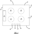
- the current technology provides a panel 10 having a top surface 12, a front edge 14, a rear edge 16, a left edge 18, and a right edge 20. At least one liquid-repelling element 22 is disposed on the top surface 12.
- the panel 10 can be incorporated into an appliance that benefits from slowing, minimizing, or preventing liquid spills from flowing off of the panel 10.
- the appliance is a cooking appliance, such as a range, a rangetop, or a stovetop, each of which can be freestanding or built into surrounding architecture, or an interior surface of an oven or a microwave. More particularly, the panel 10 is incorporated into the cooking appliance as a cooktop so that at least portions of the top surface 12 of the panel 10 are exposed to an external environment.
- the panel 10 can include at least one heating element region 24 (although four heating element regions 24 are shown in Fig. 1 ).
- the at least one heating element region 24 can accommodate or house, for example, an electric burner or a gas burner or be a surface above an electromagnet and coil for induction heating.
- the panel 10 can also include at least one control element 26 (although four control elements 26 are shown in Fig. 1 ), such as a knob and/or a button, for controlling the amount of heat provided from the at least one heating element region 24.
- the at least one control element 26 can alternatively be located on a side edge of the panel 10 or on a different surface of the cooking appliance.
- the positional configurations of the at least one heating element region 24 and the at least one control element 26 are independently exemplary and non-limiting and alternative positional configurations can be employed.
- the panel 10 is shown in a rectangular shape, it is understood that the shape is non-limiting.
- the panel 10 is defined by a substrate comprising a glass ceramic material.
- the panel 10 is also referred to herein as a "glass ceramic panel.”
- glass ceramic materials have an amorphous (glassy) phase and at least one crystalline (ceramic) phase embedded within the amorphous phase.
- Glass ceramic materials can be fabricated by, for example, subjecting a glass material to a heat treatment that controls glass nucleation and crystallization. Therefore, relative amounts of amorphous and crystalline phases can be controlled at least partially through the heat treatment. As the amount of crystalline phases increases, grain boundaries also increase, and the glass ceramic material transitions from being visibly transparent to opaque. The high strength, high impact resistance, low co-efficient of thermal expansion, and aesthetic optical properties of glass ceramic materials make them particularly suited for cooktops.
- the glass ceramic material can be an oxide material or a non-oxide material.
- oxide materials include at least one oxide, such as silicon dioxide (SiO 2 ; “silicate”), boron trioxide (B 2 O 3 ; “borate”), phosphorus pentoxide (P 2 O 5 ; “phosphate”), or germanium dioxide (GeO 2 ; “germinate”)
- non-oxide materials include a chalcogenide (group 16 element), such as sulfur (S), selenium (Se), tellurium (Te), polonium (Po), or combinations thereof, for example, as sulfides, selenides, tellurides, and/or polonides, and optionally at least one of a halide or metal.
- Non-limiting examples of oxide glass ceramics include Li 2 O-Al 2 O 3 -SiO 2 (LAS), which is a mixture of lithium, aluminum, and silicon oxides with glass forming agents, such as sodium oxide (Na 2 O), potassium oxide (K 2 O), or calcium oxide (CaO); MgO- Al 2 O 3 -SiO 2 (MAS), which is a mixture of magnesium, aluminum, and silicon oxides with glass forming agents; ZnO-Al 2 O 3 -SiO 2 (ZAS), which is a mixture of zinc, aluminum, and silicon oxides with glass forming agents; derivatives thereof; and combinations thereof.
- LAS Li 2 O-Al 2 O 3 -SiO 2
- MAS magnesium oxide
- ZnO-Al 2 O 3 -SiO 2 ZnO-Al 2 O 3 -SiO 2 (ZAS)
- the glass ceramic material is non-hydrophobic, i.e., it exhibits a water contact angle of less than or equal to about 90°, less than or equal to about 80°, less than or equal to about 70°, or less than or equal to about 60°, including water contact angles of greater than or equal to about 10° to less than or equal to about 90°, e.g., about 10°, about 20°, about 30°, about 40°, about 50°, about 60°, about 70°, about 80°, or about 90°.
- the at least one liquid-repelling element 22 comprises a film or a plurality of films disposed on the top surface 12 of the panel 10 in a discontinuous pattern.
- the film comprises a film material that is non-hydrophobic and exhibits a water contact angle of less than or equal to about 90°, less than or equal to about 80°, or less than or equal to about 70°.
- the film material exhibits a water contact angle of greater than or equal to about 20° to less than or equal to about 90°, greater than or equal to about 30° to less than or equal to about 90°, greater than or equal to about 40° to less than or equal to about 90°, greater than or equal to about 50° to less than or equal to about 90°, greater than or equal to about 20° to less than or equal to about 80°, greater than or equal to about 30° to less than or equal to about 80°, greater than or equal to about 40° to less than or equal to about 80°, greater than or equal to about 50° to less than or equal to about 80°, greater than or equal to about 20° to less than or equal to about 70°, greater than or equal to about 30° to less than or equal to about 70°, greater than or equal to about 40° to less than or equal to about 70°, or greater than or equal to about 50° to less than or equal to about 70°.
- the film material exhibits a water contact angle that is less than or equal to about 90°, but which is greater than the water contact angle exhibited by the glass ceramic material.
- the at least one liquid-repelling element 22 has a different surface energy than exposed top surfaces 12 of the panel 10 that are not covered by the at least one liquid-repelling element 22.
- the film material comprises zirconium (Zr), oxygen (O), and at least one of silicon (Si) or phosphorus (P).
- Zr zirconium
- O oxygen
- Si silicon
- P phosphorus
- the zirconium (Zr) reacts with the oxygen (O) to form a network of zirconium dioxide (ZrO 2 ).
- the zirconium dioxide (ZrO 2 ) exhibits water repellency as it does not carry hydrophilic hydroxyl (-OH) groups at the surface.
- silicon (Si) when silicon is present, it also reacts with the oxygen (O) and forms silicon dioxide (SiO 2 ) within the network of zirconium dioxide (ZrO 2 ).
- This silicon dioxide (SiO 2 ) is capable of carrying hydrophilic hydroxyl (-OH) groups and provides the film material with a hydrophilic phase. By adjusting the amount of silicon dioxide (SiO 2 ) that is formed, the film material's capability of repelling or attracting water can be modulated.
- the film material comprises zirconium dioxide (ZrO 2 ) and silicon dioxide (SiO 2 ), with the silicon dioxide (SiO 2 ) having a concentration of less than or equal to about 50 wt.% or greater than or equal to 0 wt.% to less than or equal to about 50 wt.% based on the total weight of the zirconium dioxide (ZrO 2 ) and the silicon dioxide (SiO 2 ) in the film material.
- the phosphorous (P) crosslinks with oxygen (O) atoms and provides anti-staining properties to the film material.
- the phosphorous (P) can be included in a distinct upper layer, in a concentration gradient that decreases downward from a top surface of the film to an opposing bottom surface of the film that is in direct contact with the top surface 12 of the panel 10, or dispersed substantially uniformly throughout the film.
- the phosphorous (P) when present, has a concentration of greater than or equal to about 0.001 wt.% to less than or equal to about 10 wt.% based on the total weight of the film. Examples of film material are described in U.S. Patent No. 8,709,616 , which is incorporated herein by reference in its entirety.
- each film is a single monolayer of the film material comprising, consisting essentially of, or consisting of zirconium (Zr), oxygen (O), and optionally silicon (Si) and/or phosphorous (P), without distinct sublayers.
- the film can include the phosphorus (P) as a decreasing concentration gradient from a top surface of the film to a bottom surface of the film that is in direct contact with the top surface 12 of the panel 10.
- the film is a single bilayer of the film material having a bottom layer comprising, consisting essentially of, or consisting of zirconium (Zr), oxygen (O), and optionally silicon (Si) and having a top layer comprising, consisting essentially of, or consisting of phosphorous (P).
- the at least one liquid-repelling element 22 comprises, consists essentially of, or consists of the film material.
- the term "consisting essentially of” or “consists essentially of” means that no other material is intentionally included in the respective layer or material, but that unavoidable impurities may be present at a concentration of less than or equal to about 5 wt.% based on the total weight of the respective layer or material.
- Each film has a thickness of greater than or equal to about 0.005 ⁇ m to less than or equal to about 100 ⁇ m, greater than or equal to about 0.005 ⁇ m to less than or equal to about 75 ⁇ m, greater than or equal to about 0.005 ⁇ m to less than or equal to about 50 ⁇ m, greater than or equal to about 0.005 ⁇ m to less than or equal to about 25 ⁇ m, greater than or equal to about 0.005 ⁇ m to less than or equal to about 10 ⁇ m, greater than or equal to about 0.01 ⁇ m to less than or equal to about 100 ⁇ m, greater than or equal to about 0.05 ⁇ m to less than or equal to about 100 ⁇ m, greater than or equal to about 0.1 ⁇ m to less than or equal to about 100 ⁇ m, or greater than or equal to about 1 ⁇ m to less than or equal to about 100 ⁇ m. Additionally, each film is visibly transparent so that the at least one liquid-repelling element 22 is invisible or substantially not visible to a human viewer. However,
- the film material is substantially free of hydrophobic components.
- substantially free it is meant that the film material does not intentionally include hydrophobic components, but may include less than or equal to about 5 wt.% of hydrophobic materials based on the total weight of the film as unavoidable impurities.
- the at least one liquid-repelling element 22 is disposed directly on the top surface 12 of the panel 10 in a discontinuous pattern.
- discontinuous pattern it is meant that the at least one liquid-repelling element 22 does not form a complete enclosure, such as a circle, oval, or polygon. Rather, the discontinuous pattern defines at least one line or solid shape that is configured to direct a liquid to a predetermined location.
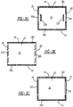
- the discontinuous pattern comprises discontinuous lines that extend about at least one edge of the panel 10 (see Figs. 2A-2D ), a plurality of segmented lines arranged in geometric patterns about at least one edge of the panel 10 (see Figs.
- a maze-type i.e., a labyrinth
- a plurality of geometric elements disposed about a central region of the panel 10 see Figs 4A-4D
- a maze-type pattern disposed about a central region of the panel 10 see Fig. 4E
- the at least one liquid-repelling element 22 can be in the form of a single line 22a that extends (substantially two-dimensionally) about at least one edge of the panel 10, such as the front edge 14 (see Fig. 2A ); a first single line 22a that extends about at least a first edge, such as the front edge 14, and a second single line 22a that extends about a second edge, such as the rear edge 16 (see Fig.
- the single lines 22a are individual and independent, i.e., having distinct end points, and can extend about a portion of an edge, about an entire edge, or about an entire edge and about a portion of at least one adjacent edge.
- the single lines 22a can be located away from an edge, i.e., not immediate about an edge. Accordingly, the single lines 22a of Figs. 2A-2D can extend substantially about the periphery of the panel 10, such as within about 20 cm, about 15 cm, or about 10 cm of the edges 14, 16, 18, 20, and are not disposed in a central region of the panel 10.
- the at least one liquid-repelling element 22 can be in the form of at least one segment line 22b or a plurality of segmented lines 22b that may extend from an edge of the panel 10 toward a central region of the panel 10 at an angle relative to the edge.
- the segmented lines 22b provide a surface texture and can be defined by, as non-limiting examples, dots, dashes, regular shapes (e.g., triangles, squares, rectangles, circles, and the like), irregular shapes, or combinations thereof, wherein each dot, dash, regular shape, or irregular shape has a diameter of greater than or equal to about 1 mm to less than or equal to about 20 mm, greater than or equal to about 1 mm to less than or equal to about 15 mm, or greater than or equal to about 1 mm to less than or equal to about 10 mm.
- the segmented lines 22b can extend about a portion of at least one edge of the panel 10, such as about a portion of the left and right edges 18, 20 (see Fig.
- the at least one liquid-repelling element 22 can also be in the form of at least one line defining a maze-type pattern 22c extending about at least one edge of the panel 10, such as about the left and right edges 18, 20 (see Fig. 3C ).
- the single lines 22a can be used together with the segmented lines 22b and the lines defining a maze-type pattern 22c.
- the at least one liquid-repelling element 22 can be in the form of a plurality of geometric elements disposed about a central region of the panel 10 or a maze-type pattern disposed about a central region of the panel 10.
- the plurality of geometric elements can be, for example, a plurality of spots, dots, or polygons 22d as shown in Fig. 4A ; a plurality of bent or wavy lines 22e as shown in Figs.
- the at least one liquid-repelling element 22 can be in the form of a maze-type pattern 22g comprising a plurality of interconnecting lines that do not define a complete enclosure, as shown in Fig. 4E .
- the single lines 22a can be used together with the plurality of spots, dots, or polygons 22d, the plurality of bent or wavy lines 22e, the plurality of open-shaped elements 22f, and/or the maze-type pattern 22g.
- the at least one liquid-repelling element 22 is configured to guide liquids to a predetermined location.
- the liquids can be aqueous, i.e., water-based, or non-aqueous, i.e., oil-based. By guiding the liquids to a predetermined location, the liquids can be wiped clean before they reach adjacent worktops or furniture.
- the panel 10 can also include a reservoir 30 that is engraved or etched into the panel 10. When present, the at least one liquid-repelling element 22 guides liquids to the reservoir 30, which holds the liquids and prevents them from flowing onto adjacent worktops or furniture.
- the reservoir 30 is only shown in Fig. 4B , it is understood that reservoirs 30 may be present in any of the exemplary configurations described above.
- the panel 10 in some aspects can also include a utensil reservoir 40 that is configured to accept a cooking utensil, such as a ladle, spoon, fork, spatula, or the like.
- the utensil reservoir 40 prevents or minimizes liquids from spilling from a cooking utensil and flowing onto the panel 10.
- the utensil reservoir 40 is depicted as an oval, the shape is not limiting.
- the utensil reservoir 40 can also be in the shape of a circle, a polygon, or an irregular shape, such as an oval or spoon-shape.
- At least one liquid-repelling element 22 can be disposed about the utensil reservoir 40 to guide spills on the cooktop into the utensil reservoir 40, similar to the function of the reservoir 30 discussed in regard to Fig. 4B .
- the utensil reservoir 40 can hold liquids originating from a cooking utensil and liquids originating from a spill on the panel 10.
- the panel 10 can be incorporated into a cooking appliance, such as a cooktop, wherein the cooktop can be a gas cooktop, an electric cooktop, or an induction cooktop. Accordingly, the current technology also provides a cooking appliance comprising the panel 10.
- the current technology further provides a method of preparing or fabricating a panel, such as the panel 10 described above.
- the method comprises disposing a precursor solution in a discontinuous pattern directly onto the surface of a blank glass ceramic panel.
- the precursor solution comprises zirconium (Zr), oxygen (O), and optionally silicon (Si).
- the zirconium (Zr) can be provided by zirconium alkoxide, a hydrolysate of zirconium alkoxide, a chelate compound of zirconium alkoxide, a chelate compound of a hydrolysate of zirconium alkoxide, zirconium oxide, and combinations thereof, as non-limiting examples.
- the silicon (Si) can be provided by any compound that can form silicon oxide through a heat treatment.
- the silicon (Si) can be provided by colloidal silica, silicon alkoxide, a hydrolysate of silicon alkoxide, and combinations thereof.
- the method then comprises performing a first heat treatment by heating the blank glass ceramic panel and the precursor solution to a temperature of greater than or equal to about 75 °C to less than or equal to about 900 °C for a time period of greater than or equal to about 5 minutes to less than or equal to about 24 hours and creating at least one liquid-repelling film on the surface having the discontinuous pattern from the precursor solution and forming the panel.
- the method optionally includes disposing a composition comprising phosphorus (P) over the at least one liquid-repelling film.
- the composition comprising phosphorus (P) can be phosphoric acids, such as phosphoric acid, polyphosphoric acid, and metaphosphoric acid; phosphates, such as sodium phosphate and sodium hydrogen phosphate; condensed phosphates, such as sodium polyphosphate, sodium metaphosphate, sodium hydrogen polyphosphate, and sodium hydrogen metaphosphate; phosphoric acid compounds, such as phosphoric acid ester; and combinations thereof.
- the phosphorus (P) becomes incorporated into the at least one liquid-repelling film.
- the second heat treatment is performed immediately after or shortly after disposing the composition comprising phosphorus (P) over the at least one liquid-repelling film, the method results in substantially distinct phosphorus (P) on the at least one liquid-repelling film.
- a phosphorus (P) concentration gradient is formed after the second heat treatment is performed.
- the phosphorus (P) is uniformly dispersed throughout the at least one liquid-repelling film, as discussed above, after the second heat treatment is performed.
- the liquid-repelling films are non-hydrophobic, exhibit a water contact angle of less than or equal to about 90°, and direct aqueous liquids to at least one predetermined location on the panel. Examples of methods of forming the liquid-repelling film are described in U.S. Patent No. 8,709,616 , which is incorporated herein by reference in its entirety, as discussed above.
- the method also comprises incorporating the panel into a cooking appliance.
Landscapes
- Chemical & Material Sciences (AREA)
- Engineering & Computer Science (AREA)
- General Chemical & Material Sciences (AREA)
- Mechanical Engineering (AREA)
- Organic Chemistry (AREA)
- Materials Engineering (AREA)
- Chemical Kinetics & Catalysis (AREA)
- Physics & Mathematics (AREA)
- Life Sciences & Earth Sciences (AREA)
- General Engineering & Computer Science (AREA)
- Combustion & Propulsion (AREA)
- Geochemistry & Mineralogy (AREA)
- Thermal Sciences (AREA)
- Metallurgy (AREA)
- Ceramic Engineering (AREA)
- Inorganic Chemistry (AREA)
- Electromagnetism (AREA)
- Dispersion Chemistry (AREA)
- Cookers (AREA)
- Surface Treatment Of Glass (AREA)
Abstract
Description
- This section provides background information related to the present disclosure which is not necessarily prior art.
- Freestanding cooking appliances are typically installed in close proximity to kitchen worktops, e.g., counters and furniture, which often are made of materials, such as wood, stone, quartz, and marble, that are sensitive to heat and/or humidity and easily stainable. When liquids spill out of cookware or other utensils onto cooktops, the cooktops are unable to retain them such that contact between the liquids and surrounding counters or furniture can be avoided. As a consequence, liquids often flow onto and contact counters and furniture, which absorb the liquids and may become permanently stained and/or otherwise damaged. These issues are also present in cooking appliances that are "built-in" or installed flush with a surrounding worktop, countertop, or island surface. Therefore, it would be beneficial for cooking appliances to be capable of trapping or slowing spills so that they can be cleaned before surrounding worktops or furniture are damaged.
- This section provides a general summary of the disclosure, and is not a comprehensive disclosure of its full scope or all of its features.
- The present disclosure relates to a spill containment and management system for glass ceramic cooktops.
- In various aspects of the present disclosure, the current technology provides a cooking appliance that includes a cooktop panel having an exposed surface and a plurality of liquid-repelling elements disposed directly on the exposed surface in a discontinuous pattern to define at least one line or shape that is configured to direct a liquid to a predetermined location on the cooktop panel. To this end, the liquid-repelling elements include a non-hydrophobic material.
- In one aspect of the present disclosure, the cooktop panel includes a glass ceramic material.
- In one aspect of the present disclosure, the liquid-repelling elements are visibly transparent.
- In one aspect of the present disclosure, liquid-repelling elements have a different surface energy than the exposed surface of the cooktop panel.
- In one aspect of the present disclosure, the liquid-repelling elements exhibit a first water contact angle that is greater than a second water contact angle exhibited by the exposed surface. The first water contact angle exhibited by the non-hydrophobic material of the liquid-repelling elements is less than or equal to about 90°.
- In one aspect of the present disclosure, the plurality of liquid-repelling elements exhibits a water contact angle greater than or equal to about 30° to less than or equal to about 70°.
- In one aspect of the present disclosure, the non-hydrophobic material forming the liquid-repelling elements is a film including zirconium dioxide (ZrO2) and silicon dioxide (SiO2). The silicon dioxide (SiO2) in the non-hydrophobic material forming the liquid-repelling elements has a concentration of less than or equal to about 50 wt.% based on the total weight of the zirconium dioxide (ZrO2) and the silicon dioxide (SiO2).
- In one aspect of the present disclosure, the film includes greater than 0 wt.% to less than or equal to about 50 wt.% silicon dioxide (SiO2) and further includes phosphorus (P). The phosphorus (P) is dispersed either substantially uniformly throughout the film or in a concentration gradient that decreases from a top surface of the film to an opposing bottom surface of the film, which is arranged in direct contact with the exposed surface of the cooktop panel.
- In one aspect of the present disclosure, the film is substantially free of silicon dioxide (SiO2) and further includes phosphorus (P). The phosphorus (P) is dispersed either substantially uniformly throughout the film or in a concentration gradient that decreases from a top surface of the film to an opposing bottom surface of the film, which is arranged in direct contact with the exposed surface of the cooktop panel.
- In one aspect of the present disclosure, the film is disposed directly on the exposed surface of the cooktop panel in a discontinuous pattern and includes zirconium (Zr), oxygen (O), and at least one of silicon (Si) or phosphorus (P). The film is non-hydrophobic and exhibits a water contact angle of less than or equal to about 90°.
- In one aspect of the present disclosure, the liquid-repelling elements are configured to guide aqueous liquids to a predetermined location on the cooktop panel.
- In one aspect of the present disclosure, the discontinuous pattern of the liquid-repelling elements comprises at least one of: discontinuous lines that extend about at least one edge of the cooktop panel, a plurality of segmented lines arranged in geometric patterns about at least one edge of the cooktop panel, at least one line defining a maze-type pattern that extends about at least one edge of the cooktop panel, a plurality of geometric elements disposed about a central region of the cooktop panel, a maze-type pattern disposed about a central region of the cooktop panel, or any combination thereof.
- In one aspect of the present disclosure, the liquid-repelling elements are substantially free of hydrophobic components.
- In one aspect of the present disclosure, the discontinuous pattern of the liquid-repelling elements does not define a complete enclosure.
- In one aspect of the present disclosure, the panel further includes at least one reservoir configured to receive and hold an aqueous liquid directed to the reservoir by the liquid-repelling elements.
- In one aspect of the present disclosure, the cooking appliance is a gas cooktop, an electric cooktop, or an induction cooktop and the cooktop panel includes at least one heating element region.
- In one aspect of the present disclosure, the cooking appliance is an oven or a microwave and the exposed surface of the cooktop panel is an interior surface of the cooking compartment of the oven or microwave. For example, the exposed surface of the cooktop panel may be configured to receive and support cookware placed inside the cooking compartment of the oven or microwave.
- In one aspect of the present disclosure, a method of preparing a cooktop panel is provided. The method includes the steps of: disposing a precursor solution in a discontinuous pattern directly onto a surface of a blank glass ceramic panel, where the precursor solution includes zirconium (Zr), oxygen (O), and optionally silicon (Si); heating the blank glass ceramic panel and the precursor solution; and creating one or more liquid-repelling films on the surface of the blank glass ceramic panel that follow the discontinuous pattern of the precursor solution, where the liquid-repelling films are non-hydrophobic, exhibit a water contact angle of less than or equal to about 90°, and direct aqueous liquids to at least one predetermined location; and forming the blank glass ceramic panel into a cooktop panel for a cooking appliance.
- In one aspect of the present disclosure, the method also includes the step of incorporating the cooktop panel into a cooking appliance.
- Further areas of applicability will become apparent from the description provided herein. The description and specific examples in this summary are intended for purposes of illustration only and are not intended to limit the scope of the present disclosure.
- The drawings described herein are for illustrative purposes only of selected embodiments and not all possible implementations, and are not intended to limit the scope of the present disclosure.
-
Fig. 1 is an illustration of a panel in accordance with various aspects of the current technology. -
Figs. 2A-2D are illustrations of a panel having liquid-repelling elements provided as discontinuous lines in accordance with various aspects of the current technology. -
Figs. 3A-3C are illustrations of a panel having liquid-repelling elements provided as segmented lines (Figs. 3A and 3B ) or as at least one line defining a maze-type pattern extending about at least one edge (Fig. 3C ) in accordance with various aspects of the current technology. -
Figs. 4A-4E are illustrations of a panel having liquid-repelling elements provided as a plurality of geometric elements (Figs. 4A-4D ) or as a maze-type pattern (Fig. 4E ) in accordance with various aspects of the current technology. -
Fig. 5 is an illustration of the panel ofFig. 1 that additionally includes a utensil reservoir in accordance with various aspects of the current technology. - Corresponding reference numerals indicate corresponding parts throughout the several views of the drawings.
- Example embodiments are provided so that this disclosure will be thorough, and will fully convey the scope to those who are skilled in the art. Numerous specific details are set forth such as examples of specific compositions, components, devices, and methods, to provide a thorough understanding of embodiments of the present disclosure. It will be apparent to those skilled in the art that specific details need not be employed, that example embodiments may be embodied in many different forms and that neither should be construed to limit the scope of the disclosure. In some example embodiments, well-known processes, well-known device structures, and well-known technologies are not described in detail.
- The terminology used herein is for the purpose of describing particular example embodiments only and is not intended to be limiting. As used herein, the singular forms "a," "an," and "the" may be intended to include the plural forms as well, unless the context clearly indicates otherwise. The terms "comprises," "comprising," "including," and "having," are inclusive and therefore specify the presence of stated features, elements, compositions, steps, integers, operations, and/or components, but do not preclude the presence or addition of one or more other features, integers, steps, operations, elements, components, and/or groups thereof. Although the open-ended term "comprising," is to be understood as a non-restrictive term used to describe and claim various embodiments set forth herein, in certain aspects, the term may alternatively be understood to instead be a more limiting and restrictive term, such as "consisting of" or "consisting essentially of." Thus, for any given embodiment reciting compositions, materials, components, elements, features, integers, operations, and/or process steps, the present disclosure also specifically includes embodiments consisting of, or consisting essentially of, such recited compositions, materials, components, elements, features, integers, operations, and/or process steps. In the case of "consisting of," the alternative embodiment excludes any additional compositions, materials, components, elements, features, integers, operations, and/or process steps, while in the case of "consisting essentially of," any additional compositions, materials, components, elements, features, integers, operations, and/or process steps that materially affect the basic and novel characteristics are excluded from such an embodiment, but any compositions, materials, components, elements, features, integers, operations, and/or process steps that do not materially affect the basic and novel characteristics can be included in the embodiment.
- Any method steps, processes, and operations described herein are not to be construed as necessarily requiring their performance in the particular order discussed or illustrated, unless specifically identified as an order of performance. It is also to be understood that additional or alternative steps may be employed, unless otherwise indicated.
- When a component, element, or layer is referred to as being "on," "engaged to," "connected to," or "coupled to" another element or layer, it may be directly on, engaged, connected or coupled to the other component, element, or layer, or intervening elements or layers may be present. In contrast, when an element is referred to as being "directly on," "directly engaged to," "directly connected to," or "directly coupled to" another element or layer, there may be no intervening elements or layers present. Other words used to describe the relationship between elements should be interpreted in a like fashion (e.g., "between" versus "directly between," "adjacent" versus "directly adjacent," etc.). As used herein, the term "and/or" includes any and all combinations of one or more of the associated listed items.
- Although the terms first, second, third, etc. may be used herein to describe various steps, elements, components, regions, layers and/or sections, these steps, elements, components, regions, layers and/or sections should not be limited by these terms, unless otherwise indicated. These terms may be only used to distinguish one step, element, component, region, layer or section from another step, element, component, region, layer or section. Terms such as "first," "second," and other numerical terms when used herein do not imply a sequence or order unless clearly indicated by the context. Thus, a first step, element, component, region, layer or section discussed below could be termed a second step, element, component, region, layer or section without departing from the teachings of the example embodiments.
- Spatially or temporally relative terms, such as "before," "after," "inner," "outer," "beneath," "below," "lower," "above," "upper," and the like, may be used herein for ease of description to describe one element or feature's relationship to another element(s) or feature(s) as illustrated in the figures. Spatially or temporally relative terms may be intended to encompass different orientations of the device or system in use or operation in addition to the orientation depicted in the figures.
- Throughout this disclosure, the numerical values represent approximate measures or limits to ranges to encompass minor deviations from the given values and embodiments having about the value mentioned as well as those having exactly the value mentioned. Other than in the working examples provided at the end of the detailed description, all numerical values of parameters (e.g., of quantities or conditions) in this specification, including the appended claims, are to be understood as being modified in all instances by the term "about" whether or not "about" actually appears before the numerical value. "About" indicates that the stated numerical value allows some slight imprecision (with some approach to exactness in the value; approximately or reasonably close to the value; nearly). If the imprecision provided by "about" is not otherwise understood in the art with this ordinary meaning, then "about" as used herein indicates at least variations that may arise from ordinary methods of measuring and using such parameters. For example, "about" may comprise a variation of less than or equal to 5%, optionally less than or equal to 4%, optionally less than or equal to 3%, optionally less than or equal to 2%, optionally less than or equal to 1%, optionally less than or equal to 0.5%, and in certain aspects, optionally less than or equal to 0.1%.
- In addition, disclosure of ranges includes disclosure of all values and further divided ranges within the entire range, including endpoints and sub-ranges given for the ranges.
- Example embodiments will now be described more fully with reference to the accompanying drawings.
- When liquids, including hot liquids, are spilled onto surfaces of cooktops, the liquids may contact, stain, or otherwise damage adjacent worktops or furniture. Accordingly, the current technology provides cooktops having liquid-directing and/or liquid-containing elements that slow, minimize, or prevent the spilled liquids from flowing off of cooktops. As a result, a user is capable of cleaning liquid spills before the adjacent worktops or furniture are stained or damaged.
- With reference to
Fig. 1 , the current technology provides apanel 10 having atop surface 12, afront edge 14, arear edge 16, aleft edge 18, and aright edge 20. At least one liquid-repelling element 22 is disposed on thetop surface 12. Thepanel 10 can be incorporated into an appliance that benefits from slowing, minimizing, or preventing liquid spills from flowing off of thepanel 10. In certain aspects, the appliance is a cooking appliance, such as a range, a rangetop, or a stovetop, each of which can be freestanding or built into surrounding architecture, or an interior surface of an oven or a microwave. More particularly, thepanel 10 is incorporated into the cooking appliance as a cooktop so that at least portions of thetop surface 12 of thepanel 10 are exposed to an external environment. As a component of a cooking appliance, thepanel 10 can include at least one heating element region 24 (although fourheating element regions 24 are shown inFig. 1 ). The at least oneheating element region 24 can accommodate or house, for example, an electric burner or a gas burner or be a surface above an electromagnet and coil for induction heating. In some aspects, thepanel 10 can also include at least one control element 26 (although fourcontrol elements 26 are shown inFig. 1 ), such as a knob and/or a button, for controlling the amount of heat provided from the at least oneheating element region 24. However, the at least onecontrol element 26 can alternatively be located on a side edge of thepanel 10 or on a different surface of the cooking appliance. It is understood that the positional configurations of the at least oneheating element region 24 and the at least onecontrol element 26 are independently exemplary and non-limiting and alternative positional configurations can be employed. Although thepanel 10 is shown in a rectangular shape, it is understood that the shape is non-limiting. - The
panel 10 is defined by a substrate comprising a glass ceramic material. As such, thepanel 10 is also referred to herein as a "glass ceramic panel." As is known in the art, glass ceramic materials have an amorphous (glassy) phase and at least one crystalline (ceramic) phase embedded within the amorphous phase. Glass ceramic materials can be fabricated by, for example, subjecting a glass material to a heat treatment that controls glass nucleation and crystallization. Therefore, relative amounts of amorphous and crystalline phases can be controlled at least partially through the heat treatment. As the amount of crystalline phases increases, grain boundaries also increase, and the glass ceramic material transitions from being visibly transparent to opaque. The high strength, high impact resistance, low co-efficient of thermal expansion, and aesthetic optical properties of glass ceramic materials make them particularly suited for cooktops. - The glass ceramic material can be an oxide material or a non-oxide material. Whereas oxide materials include at least one oxide, such as silicon dioxide (SiO2; "silicate"), boron trioxide (B2O3; "borate"), phosphorus pentoxide (P2O5; "phosphate"), or germanium dioxide (GeO2; "germinate"), non-oxide materials include a chalcogenide (
group 16 element), such as sulfur (S), selenium (Se), tellurium (Te), polonium (Po), or combinations thereof, for example, as sulfides, selenides, tellurides, and/or polonides, and optionally at least one of a halide or metal. Non-limiting examples of oxide glass ceramics include Li2O-Al2O3-SiO2 (LAS), which is a mixture of lithium, aluminum, and silicon oxides with glass forming agents, such as sodium oxide (Na2O), potassium oxide (K2O), or calcium oxide (CaO); MgO- Al2O3-SiO2 (MAS), which is a mixture of magnesium, aluminum, and silicon oxides with glass forming agents; ZnO-Al2O3-SiO2 (ZAS), which is a mixture of zinc, aluminum, and silicon oxides with glass forming agents; derivatives thereof; and combinations thereof. It is understood that "derivatives" of the above-listed oxide glass ceramics retain the same general composition, but include additional or alternative components or microstructures resulting from various thermal treatments. The glass ceramic material is non-hydrophobic, i.e., it exhibits a water contact angle of less than or equal to about 90°, less than or equal to about 80°, less than or equal to about 70°, or less than or equal to about 60°, including water contact angles of greater than or equal to about 10° to less than or equal to about 90°, e.g., about 10°, about 20°, about 30°, about 40°, about 50°, about 60°, about 70°, about 80°, or about 90°. - The at least one liquid-repelling element 22 comprises a film or a plurality of films disposed on the
top surface 12 of thepanel 10 in a discontinuous pattern. The film comprises a film material that is non-hydrophobic and exhibits a water contact angle of less than or equal to about 90°, less than or equal to about 80°, or less than or equal to about 70°. In certain aspects, the film material exhibits a water contact angle of greater than or equal to about 20° to less than or equal to about 90°, greater than or equal to about 30° to less than or equal to about 90°, greater than or equal to about 40° to less than or equal to about 90°, greater than or equal to about 50° to less than or equal to about 90°, greater than or equal to about 20° to less than or equal to about 80°, greater than or equal to about 30° to less than or equal to about 80°, greater than or equal to about 40° to less than or equal to about 80°, greater than or equal to about 50° to less than or equal to about 80°, greater than or equal to about 20° to less than or equal to about 70°, greater than or equal to about 30° to less than or equal to about 70°, greater than or equal to about 40° to less than or equal to about 70°, or greater than or equal to about 50° to less than or equal to about 70°. In certain aspects, the film material exhibits a water contact angle that is less than or equal to about 90°, but which is greater than the water contact angle exhibited by the glass ceramic material. As such, the at least one liquid-repelling element 22 has a different surface energy than exposedtop surfaces 12 of thepanel 10 that are not covered by the at least one liquid-repelling element 22. - The film material comprises zirconium (Zr), oxygen (O), and at least one of silicon (Si) or phosphorus (P). During its formation, the zirconium (Zr) reacts with the oxygen (O) to form a network of zirconium dioxide (ZrO2). The zirconium dioxide (ZrO2) exhibits water repellency as it does not carry hydrophilic hydroxyl (-OH) groups at the surface. However, when silicon (Si) is present, it also reacts with the oxygen (O) and forms silicon dioxide (SiO2) within the network of zirconium dioxide (ZrO2). This silicon dioxide (SiO2) is capable of carrying hydrophilic hydroxyl (-OH) groups and provides the film material with a hydrophilic phase. By adjusting the amount of silicon dioxide (SiO2) that is formed, the film material's capability of repelling or attracting water can be modulated. In some aspects, the film material comprises zirconium dioxide (ZrO2) and silicon dioxide (SiO2), with the silicon dioxide (SiO2) having a concentration of less than or equal to about 50 wt.% or greater than or equal to 0 wt.% to less than or equal to about 50 wt.% based on the total weight of the zirconium dioxide (ZrO2) and the silicon dioxide (SiO2) in the film material. When present, the phosphorous (P) crosslinks with oxygen (O) atoms and provides anti-staining properties to the film material. The phosphorous (P) can be included in a distinct upper layer, in a concentration gradient that decreases downward from a top surface of the film to an opposing bottom surface of the film that is in direct contact with the
top surface 12 of thepanel 10, or dispersed substantially uniformly throughout the film. The phosphorous (P), when present, has a concentration of greater than or equal to about 0.001 wt.% to less than or equal to about 10 wt.% based on the total weight of the film. Examples of film material are described inU.S. Patent No. 8,709,616 , which is incorporated herein by reference in its entirety. - In certain aspects, each film is a single monolayer of the film material comprising, consisting essentially of, or consisting of zirconium (Zr), oxygen (O), and optionally silicon (Si) and/or phosphorous (P), without distinct sublayers. However, the film can include the phosphorus (P) as a decreasing concentration gradient from a top surface of the film to a bottom surface of the film that is in direct contact with the
top surface 12 of thepanel 10. In other aspects, the film is a single bilayer of the film material having a bottom layer comprising, consisting essentially of, or consisting of zirconium (Zr), oxygen (O), and optionally silicon (Si) and having a top layer comprising, consisting essentially of, or consisting of phosphorous (P). The film or plurality of films can be disposed directly on thetop surface 12 of thepanel 10 without any intervening or intermediate layers disposed between the film or plurality of films and thetop surface 12 of thepanel 10. Accordingly, the at least one liquid-repelling element 22 comprises, consists essentially of, or consists of the film material. As used herein, the term "consisting essentially of" or "consists essentially of" means that no other material is intentionally included in the respective layer or material, but that unavoidable impurities may be present at a concentration of less than or equal to about 5 wt.% based on the total weight of the respective layer or material. Each film has a thickness of greater than or equal to about 0.005 µm to less than or equal to about 100 µm, greater than or equal to about 0.005 µm to less than or equal to about 75 µm, greater than or equal to about 0.005 µm to less than or equal to about 50 µm, greater than or equal to about 0.005 µm to less than or equal to about 25 µm, greater than or equal to about 0.005 µm to less than or equal to about 10 µm, greater than or equal to about 0.01 µm to less than or equal to about 100 µm, greater than or equal to about 0.05 µm to less than or equal to about 100 µm, greater than or equal to about 0.1 µm to less than or equal to about 100 µm, or greater than or equal to about 1 µm to less than or equal to about 100 µm. Additionally, each film is visibly transparent so that the at least one liquid-repelling element 22 is invisible or substantially not visible to a human viewer. However, it is understood that each film can be dyed to a desired color. - The film material is substantially free of hydrophobic components. By "substantially free," it is meant that the film material does not intentionally include hydrophobic components, but may include less than or equal to about 5 wt.% of hydrophobic materials based on the total weight of the film as unavoidable impurities.
- The at least one liquid-repelling element 22 is disposed directly on the
top surface 12 of thepanel 10 in a discontinuous pattern. By "discontinuous pattern," it is meant that the at least one liquid-repelling element 22 does not form a complete enclosure, such as a circle, oval, or polygon. Rather, the discontinuous pattern defines at least one line or solid shape that is configured to direct a liquid to a predetermined location. The discontinuous pattern comprises discontinuous lines that extend about at least one edge of the panel 10 (seeFigs. 2A-2D ), a plurality of segmented lines arranged in geometric patterns about at least one edge of the panel 10 (seeFigs. 3A-3B ), at least one line defining a maze-type (i.e., a labyrinth) pattern that extends about at least one edge of the panel 10 (seeFig. 3C ), a plurality of geometric elements disposed about a central region of the panel 10 (seeFigs 4A-4D ), a maze-type pattern disposed about a central region of the panel 10 (seeFig. 4E ), or a combination thereof. - As shown in
Figs. 2A-2D , which depict thepanel 10 ofFig. 1 with the at least oneheating element region 24 and the at least onecontrol element 26 excluded for clarity, the at least one liquid-repelling element 22 can be in the form of asingle line 22a that extends (substantially two-dimensionally) about at least one edge of thepanel 10, such as the front edge 14 (seeFig. 2A ); a firstsingle line 22a that extends about at least a first edge, such as thefront edge 14, and a secondsingle line 22a that extends about a second edge, such as the rear edge 16 (seeFig. 2B ); a firstsingle line 22a that extends about at least three edges, such as theleft edge 18, therear edge 16, and theright edge 20, and a secondsingle line 22a that extends about a portion of a fourth edge, such as the front edge 14 (seeFig. 2C ); or asingle line 22a that extends about three edges, such as theleft edge 18, thefront edge 14, and theright edge 20, and that further extends about or near a portion of a fourth edge, such as the rear edge 16 (seeFig. 2D ). Therefore, thesingle lines 22a are individual and independent, i.e., having distinct end points, and can extend about a portion of an edge, about an entire edge, or about an entire edge and about a portion of at least one adjacent edge. As shown inFig. 2D , thesingle lines 22a can be located away from an edge, i.e., not immediate about an edge. Accordingly, thesingle lines 22a ofFigs. 2A-2D can extend substantially about the periphery of thepanel 10, such as within about 20 cm, about 15 cm, or about 10 cm of theedges panel 10. - As shown in
Figs. 3A and 3B , which depict thepanel 10 ofFig. 1 with the at least oneheating element region 24 and the at least onecontrol element 26 excluded for clarity, the at least one liquid-repelling element 22 can be in the form of at least onesegment line 22b or a plurality ofsegmented lines 22b that may extend from an edge of thepanel 10 toward a central region of thepanel 10 at an angle relative to the edge. Thesegmented lines 22b provide a surface texture and can be defined by, as non-limiting examples, dots, dashes, regular shapes (e.g., triangles, squares, rectangles, circles, and the like), irregular shapes, or combinations thereof, wherein each dot, dash, regular shape, or irregular shape has a diameter of greater than or equal to about 1 mm to less than or equal to about 20 mm, greater than or equal to about 1 mm to less than or equal to about 15 mm, or greater than or equal to about 1 mm to less than or equal to about 10 mm. As non-limiting examples, thesegmented lines 22b can extend about a portion of at least one edge of thepanel 10, such as about a portion of the left andright edges 18, 20 (seeFig. 3A ), or about at least one whole edge of thepanel 10, such as about the whole left andright edges 18, 20 (seeFig. 3B ). The at least one liquid-repelling element 22 can also be in the form of at least one line defining a maze-type pattern 22c extending about at least one edge of thepanel 10, such as about the left andright edges 18, 20 (seeFig. 3C ). As shown inFigs. 3A-3C , thesingle lines 22a can be used together with thesegmented lines 22b and the lines defining a maze-type pattern 22c. - As shown in
Figs. 4A-4D , which depict thepanel 10 ofFig. 1 with the at least oneheating element region 24 and the at least onecontrol element 26 excluded for clarity, the at least one liquid-repelling element 22 can be in the form of a plurality of geometric elements disposed about a central region of thepanel 10 or a maze-type pattern disposed about a central region of thepanel 10. The plurality of geometric elements can be, for example, a plurality of spots, dots, orpolygons 22d as shown inFig. 4A ; a plurality of bent orwavy lines 22e as shown inFigs. 4B and 4C ; or a plurality of open-shapedelements 22f that each provide an opening that leads to internal containment area or region, such as a plurality of C-shaped elements, as shown inFig. 4D . Alternatively, the at least one liquid-repelling element 22 can be in the form of a maze-type pattern 22g comprising a plurality of interconnecting lines that do not define a complete enclosure, as shown inFig. 4E . As shown inFigs. 4A-4E , thesingle lines 22a can be used together with the plurality of spots, dots, orpolygons 22d, the plurality of bent orwavy lines 22e, the plurality of open-shapedelements 22f, and/or the maze-type pattern 22g. - The at least one liquid-repelling element 22 is configured to guide liquids to a predetermined location. The liquids can be aqueous, i.e., water-based, or non-aqueous, i.e., oil-based. By guiding the liquids to a predetermined location, the liquids can be wiped clean before they reach adjacent worktops or furniture. In some aspects, as shown in
Fig. 4B , thepanel 10 can also include areservoir 30 that is engraved or etched into thepanel 10. When present, the at least one liquid-repelling element 22 guides liquids to thereservoir 30, which holds the liquids and prevents them from flowing onto adjacent worktops or furniture. Although thereservoir 30 is only shown inFig. 4B , it is understood thatreservoirs 30 may be present in any of the exemplary configurations described above. - With reference to
Fig. 5 , thepanel 10 in some aspects can also include a utensil reservoir 40 that is configured to accept a cooking utensil, such as a ladle, spoon, fork, spatula, or the like. The utensil reservoir 40 prevents or minimizes liquids from spilling from a cooking utensil and flowing onto thepanel 10. Although the utensil reservoir 40 is depicted as an oval, the shape is not limiting. For example, the utensil reservoir 40 can also be in the shape of a circle, a polygon, or an irregular shape, such as an oval or spoon-shape. In some aspects, at least one liquid-repelling element 22 can be disposed about the utensil reservoir 40 to guide spills on the cooktop into the utensil reservoir 40, similar to the function of thereservoir 30 discussed in regard toFig. 4B . As such, the utensil reservoir 40 can hold liquids originating from a cooking utensil and liquids originating from a spill on thepanel 10. - As discussed above, the
panel 10 can be incorporated into a cooking appliance, such as a cooktop, wherein the cooktop can be a gas cooktop, an electric cooktop, or an induction cooktop. Accordingly, the current technology also provides a cooking appliance comprising thepanel 10. - The current technology further provides a method of preparing or fabricating a panel, such as the
panel 10 described above. The method comprises disposing a precursor solution in a discontinuous pattern directly onto the surface of a blank glass ceramic panel. The precursor solution comprises zirconium (Zr), oxygen (O), and optionally silicon (Si). The zirconium (Zr) can be provided by zirconium alkoxide, a hydrolysate of zirconium alkoxide, a chelate compound of zirconium alkoxide, a chelate compound of a hydrolysate of zirconium alkoxide, zirconium oxide, and combinations thereof, as non-limiting examples. When present, the silicon (Si) can be provided by any compound that can form silicon oxide through a heat treatment. As non-limiting examples, the silicon (Si) can be provided by colloidal silica, silicon alkoxide, a hydrolysate of silicon alkoxide, and combinations thereof. The method then comprises performing a first heat treatment by heating the blank glass ceramic panel and the precursor solution to a temperature of greater than or equal to about 75 °C to less than or equal to about 900 °C for a time period of greater than or equal to about 5 minutes to less than or equal to about 24 hours and creating at least one liquid-repelling film on the surface having the discontinuous pattern from the precursor solution and forming the panel. The method optionally includes disposing a composition comprising phosphorus (P) over the at least one liquid-repelling film. As non-limiting examples, the composition comprising phosphorus (P) can be phosphoric acids, such as phosphoric acid, polyphosphoric acid, and metaphosphoric acid; phosphates, such as sodium phosphate and sodium hydrogen phosphate; condensed phosphates, such as sodium polyphosphate, sodium metaphosphate, sodium hydrogen polyphosphate, and sodium hydrogen metaphosphate; phosphoric acid compounds, such as phosphoric acid ester; and combinations thereof. By performing an optional second heat treatment by heating to a temperature of greater than or equal to about 75 °C to less than or equal to about 500 °C for a time period of greater than or equal to about 5 minutes to less than or equal to about 24 hours, the phosphorus (P) becomes incorporated into the at least one liquid-repelling film. When the second heat treatment is performed immediately after or shortly after disposing the composition comprising phosphorus (P) over the at least one liquid-repelling film, the method results in substantially distinct phosphorus (P) on the at least one liquid-repelling film. By allowing the composition comprising phosphorus (P) to partially absorb into the at least one liquid-repelling film prior to the second heat treatment, a phosphorus (P) concentration gradient, as discussed above, is formed after the second heat treatment is performed. By allowing the composition comprising phosphorus (P) to completely absorb into the at least one liquid-repelling film prior to the second heat treatment, the phosphorus (P) is uniformly dispersed throughout the at least one liquid-repelling film, as discussed above, after the second heat treatment is performed. The liquid-repelling films are non-hydrophobic, exhibit a water contact angle of less than or equal to about 90°, and direct aqueous liquids to at least one predetermined location on the panel. Examples of methods of forming the liquid-repelling film are described inU.S. Patent No. 8,709,616 , which is incorporated herein by reference in its entirety, as discussed above. - In some aspects, the method also comprises incorporating the panel into a cooking appliance.
- The foregoing description of the embodiments has been provided for purposes of illustration and description. It is not intended to be exhaustive or to limit the disclosure. Individual elements or features of a particular embodiment are generally not limited to that particular embodiment, but, where applicable, are interchangeable and can be used in a selected embodiment, even if not specifically shown or described. The same may also be varied in many ways. Such variations are not to be regarded as a departure from the disclosure, and all such modifications are intended to be included within the scope of the disclosure.
Claims (15)
- A cooking appliance, comprising:a cooktop panel (10) having an exposed surface (12); anda plurality of liquid-repelling elements (22) disposed directly on the exposed surface (12) of the cooktop panel (10) in a discontinuous pattern to define at least one line or shape that is configured to direct a liquid to a predetermined location on the cooktop panel (10),wherein the liquid-repelling elements (22) comprise a non-hydrophobic material.
- The cooking appliance according to Claim 1, wherein the cooktop panel (10) comprises a glass ceramic material.
- The cooking appliance according to Claims 1 or 2, wherein the non-hydrophobic material forming the liquid-repelling elements (22) is a film comprising zirconium dioxide (ZrO2) and silicon dioxide (SiO2), the silicon dioxide (SiO2) having a concentration of less than or equal to about 50 wt.% based on the total weight of the zirconium dioxide (ZrO2) and the silicon dioxide (SiO2).
- The cooking appliance according to Claim 3, wherein the film comprises greater than 0 wt.% to less than or equal to about 50 wt.% silicon dioxide (SiO2) and the film further comprises phosphorus (P), the phosphorus (P) being dispersed either substantially uniformly throughout the film or in a concentration gradient that decreases from a top surface of the film to an opposing bottom surface of the film that is in direct contact with the exposed surface (12) of the cooktop panel (10).
- The cooking appliance according to Claim 3, wherein the film is substantially free of silicon dioxide (SiO2) and the film further comprises phosphorus (P), the phosphorus (P) being dispersed either substantially uniformly throughout the film or in a concentration gradient that decreases from a top surface of the film to an opposing bottom surface of the film that is in direct contact with the exposed surface (12) of the cooktop panel (10).
- The cooking appliance according to Claims 1 or 2, wherein the non-hydrophobic material forming the liquid-repelling elements (22) is a film that exhibits a water contact angle of less than or equal to about 90°, the film comprising zirconium (Zr), oxygen (O), and at least one of silicon (Si) or phosphorus (P).
- The cooking appliance according Claims 1 or 2, wherein the liquid-repelling elements (22) have a different surface energy than the exposed surface (12).
- The cooking appliance according to Claims 1 or 2, wherein the liquid-repelling elements (22) are visibly transparent.
- The cooking appliance according to Claim 1, wherein the cooking appliance is a gas cooktop, an electric cooktop, or an induction cooktop and the cooktop panel (10) includes at least one heating element region (24).
- The cooking appliance according to Claim 1, wherein the cooking appliance is an oven or a microwave and the exposed surface (12) of the cooktop panel (10) is an interior surface of the oven or microwave.
- The cooking appliance according to Claim 1, wherein the non-hydrophobic material of the liquid-repelling elements (22) exhibits a first water contact angle that is greater than a second water contact angle exhibited by the exposed surface (12) and the first water contact angle exhibited by the non-hydrophobic material of the liquid-repelling elements (22) is less than or equal to about 90°.
- The cooking appliance according to Claim 1, wherein the non-hydrophobic material of the liquid-repelling elements (22) exhibits a water contact angle that is greater than or equal to about 30° to less than or equal to about 70°.
- The cooking appliance according to Claim 1, wherein the liquid-repelling elements (22) are configured to guide aqueous liquids to the predetermined location on the cooktop panel (10).
- The cooking appliance according to Claim 1, wherein the discontinuous pattern of the liquid-repelling elements (22) comprises at least one of:discontinuous lines that extend about at least one edge (14, 16, 18, 20) of the cooktop panel (10);a plurality of segmented lines arranged in geometric patterns about at least one edge (14, 16, 18, 20) of the cooktop panel (10);at least one line defining a maze-type pattern that extends about at least one edge (14, 16, 18, 20) of the cooktop panel (10);a plurality of geometric elements disposed about a central region of the cooktop panel (10);a maze-type pattern disposed about a central region of the cooktop panel (10); ora combination thereof.
- The cooking appliance according to Claim 1, wherein the discontinuous pattern of the liquid-repelling elements (22) does not define a complete enclosure.
Applications Claiming Priority (1)
| Application Number | Priority Date | Filing Date | Title |
|---|---|---|---|
| US17/138,368 US12129202B2 (en) | 2020-12-30 | 2020-12-30 | Spill containment and management system for glass ceramic cooktop |
Publications (1)
| Publication Number | Publication Date |
|---|---|
| EP4023617A1 true EP4023617A1 (en) | 2022-07-06 |
Family
ID=81828063
Family Applications (1)
| Application Number | Title | Priority Date | Filing Date |
|---|---|---|---|
| EP21205424.1A Pending EP4023617A1 (en) | 2020-12-30 | 2021-10-28 | Spill containment and management system for glass ceramic cooktop |
Country Status (2)
| Country | Link |
|---|---|
| US (2) | US12129202B2 (en) |
| EP (1) | EP4023617A1 (en) |
Citations (2)
| Publication number | Priority date | Publication date | Assignee | Title |
|---|---|---|---|---|
| WO2011056742A1 (en) * | 2009-11-04 | 2011-05-12 | Ssw Holding Company, Inc. | Cooking appliance surfaces having spill containment pattern and methods of making the same |
| US8709616B2 (en) | 2007-01-30 | 2014-04-29 | Sumitomo Osaka Cement, Co., Ltd. | Cooking device and method of manufacture of the same |
Family Cites Families (16)
| Publication number | Priority date | Publication date | Assignee | Title |
|---|---|---|---|---|
| US3354022A (en) | 1964-03-31 | 1967-11-21 | Du Pont | Water-repellant surface |
| JPH04124047A (en) | 1990-09-17 | 1992-04-24 | Nissan Motor Co Ltd | Method for water repellent treatment of glass surface |
| US5815995A (en) | 1996-08-01 | 1998-10-06 | Diversified Industrial Technologies, Inc. | Slip-resistant floor covering system |
| JP2000314015A (en) | 1999-04-27 | 2000-11-14 | Mizuno Corp | Swimsuit |
| EP1136539A4 (en) | 1999-08-02 | 2002-10-09 | Nippon Sheet Glass Co Ltd | Article coated with water-repellent film, liquid composition for coating with water-repellent film, and process for producing article coated with water-repellent film |
| US6531206B2 (en) | 2001-02-07 | 2003-03-11 | 3M Innovative Properties Company | Microstructured surface film assembly for liquid acquisition and transport |
| KR20080080682A (en) | 2001-05-30 | 2008-09-04 | 토토 가부시키가이샤 | Floor panels for the bathroom |
| JP2004251095A (en) | 2002-12-27 | 2004-09-09 | Hitachi Housetec Co Ltd | Waterproof pan |
| JP2009052826A (en) | 2007-08-28 | 2009-03-12 | Sumitomo Osaka Cement Co Ltd | Top plate for cooking stove and its manufacturing method |
| US8286561B2 (en) | 2008-06-27 | 2012-10-16 | Ssw Holding Company, Inc. | Spill containing refrigerator shelf assembly |
| EP2346678B1 (en) | 2008-10-07 | 2017-10-04 | Ross Technology Corporation | Spill resistant surfaces having hydrophobic and oleophobic borders |
| WO2010096073A1 (en) | 2009-02-17 | 2010-08-26 | The Board Of Trustees Of The University Of Illinois | Flexible microstructured superhydrophobic materials |
| DE102011085428A1 (en) | 2011-10-28 | 2013-05-02 | Schott Ag | shelf |
| ES2660430B1 (en) | 2016-07-21 | 2019-01-02 | Bsh Electrodomesticos Espana Sa | Plate of cooking field and cooking field with said plate |
| ES2702791A1 (en) | 2017-09-05 | 2019-03-05 | Bsh Electrodomesticos Espana Sa | CONTROL DEVICE FOR A DOMESTIC APPLIANCES AND DOMESTIC APPLIANCE (Machine-translation by Google Translate, not legally binding) |
| FR3071909B1 (en) * | 2017-09-29 | 2019-10-18 | Eurokera S.N.C. | VITROCERAMIC PLATE COMPRISING A CORD FOR RETAINING LIQUIDS. |
-
2020
- 2020-12-30 US US17/138,368 patent/US12129202B2/en active Active
-
2021
- 2021-10-28 EP EP21205424.1A patent/EP4023617A1/en active Pending
-
2024
- 2024-10-07 US US18/908,273 patent/US20250034035A1/en active Pending
Patent Citations (2)
| Publication number | Priority date | Publication date | Assignee | Title |
|---|---|---|---|---|
| US8709616B2 (en) | 2007-01-30 | 2014-04-29 | Sumitomo Osaka Cement, Co., Ltd. | Cooking device and method of manufacture of the same |
| WO2011056742A1 (en) * | 2009-11-04 | 2011-05-12 | Ssw Holding Company, Inc. | Cooking appliance surfaces having spill containment pattern and methods of making the same |
Also Published As
| Publication number | Publication date |
|---|---|
| US12129202B2 (en) | 2024-10-29 |
| US20220204396A1 (en) | 2022-06-30 |
| US20250034035A1 (en) | 2025-01-30 |
Similar Documents
| Publication | Publication Date | Title |
|---|---|---|
| CN103025674B (en) | As the glass-ceramic for the color display capabilities with improvement of induction heater and the cooktop of gear heat energy power, the preparation method and its usage of this cooktop | |
| JP7097783B2 (en) | Colored transparent lithium aluminum silicate glass ceramic and its use | |
| CN1211307C (en) | Easy-to-clean glass ceramic body | |
| KR102631331B1 (en) | Transparent β-quartz glass-ceramic with low lithium content | |
| JP5840568B2 (en) | As a cooking surface, glass ceramic is strong, colored and smooth on both sides | |
| JP6050321B2 (en) | Electromagnetic cooker | |
| KR102079537B1 (en) | Glass-ceramic article and manufacturing method | |
| KR101824280B1 (en) | Cooking device | |
| CN103443043B (en) | Glass or glass-ceramic products with a high-temperature stable low-energy layer | |
| KR101971297B1 (en) | Induction cooking device | |
| ES2724674T3 (en) | Process for the production of a coated substrate, of a plate-shaped substrate, comprising at least two layers applied by means of heating, and use of the coated substrate | |
| JP2019112299A (en) | Colored fireplace window having transmission characteristics of neutral colors | |
| CN108025962B (en) | Method for producing a tempered glass article with a durable functional coating and tempered glass article with a durable functional coating | |
| JP2016169146A (en) | Substrate coated with noise-optimized glass-based coating and method of producing such coating | |
| JP2016169147A (en) | Manufacturing method of glass or glass ceramic product containing coloring glass-based coating, coated glass or glass ceramic product and use thereof | |
| US11479500B2 (en) | Enamel composition, method for preparing enamel composition, and cooking appliance | |
| CN104968624A (en) | Glass-ceramic item and enamel suitable for coating same | |
| EP2961703B1 (en) | Non-opaque arsenic-free beta-spodumene glass ceramic exhibiting brown-grey coloration | |
| US12129202B2 (en) | Spill containment and management system for glass ceramic cooktop | |
| JP3172578U (en) | Glass ceramic plate, method of obtaining the plate, display device including the plate, and cooking machine including the plate | |
| JP2023155254A (en) | Glass ceramic plate containing liquid retention beads | |
| US8770183B2 (en) | Glass article | |
| JP6014797B2 (en) | Ceramic container | |
| CN119998244A (en) | Glass-ceramic articles and methods of making such articles | |
| JP2013087986A (en) | Glass plate for top plate for cooker and method of manufacturing the same |
Legal Events
| Date | Code | Title | Description |
|---|---|---|---|
| PUAI | Public reference made under article 153(3) epc to a published international application that has entered the european phase |
Free format text: ORIGINAL CODE: 0009012 |
|
| STAA | Information on the status of an ep patent application or granted ep patent |
Free format text: STATUS: THE APPLICATION HAS BEEN PUBLISHED |
|
| AK | Designated contracting states |
Kind code of ref document: A1 Designated state(s): AL AT BE BG CH CY CZ DE DK EE ES FI FR GB GR HR HU IE IS IT LI LT LU LV MC MK MT NL NO PL PT RO RS SE SI SK SM TR |
|
| STAA | Information on the status of an ep patent application or granted ep patent |
Free format text: STATUS: REQUEST FOR EXAMINATION WAS MADE |
|
| 17P | Request for examination filed |
Effective date: 20230105 |
|
| RBV | Designated contracting states (corrected) |
Designated state(s): AL AT BE BG CH CY CZ DE DK EE ES FI FR GB GR HR HU IE IS IT LI LT LU LV MC MK MT NL NO PL PT RO RS SE SI SK SM TR |
|
| RAP3 | Party data changed (applicant data changed or rights of an application transferred) |
Owner name: WHIRLPOOL CORPORATION |