EP4023548A2 - Wing detachment assembly and aircraft - Google Patents
Wing detachment assembly and aircraft Download PDFInfo
- Publication number
- EP4023548A2 EP4023548A2 EP20860994.1A EP20860994A EP4023548A2 EP 4023548 A2 EP4023548 A2 EP 4023548A2 EP 20860994 A EP20860994 A EP 20860994A EP 4023548 A2 EP4023548 A2 EP 4023548A2
- Authority
- EP
- European Patent Office
- Prior art keywords
- wing
- thumb wheel
- connecting portion
- vehicle body
- hole
- Prior art date
- Legal status (The legal status is an assumption and is not a legal conclusion. Google has not performed a legal analysis and makes no representation as to the accuracy of the status listed.)
- Granted
Links
Images



Classifications
-
- F—MECHANICAL ENGINEERING; LIGHTING; HEATING; WEAPONS; BLASTING
- F16—ENGINEERING ELEMENTS AND UNITS; GENERAL MEASURES FOR PRODUCING AND MAINTAINING EFFECTIVE FUNCTIONING OF MACHINES OR INSTALLATIONS; THERMAL INSULATION IN GENERAL
- F16B—DEVICES FOR FASTENING OR SECURING CONSTRUCTIONAL ELEMENTS OR MACHINE PARTS TOGETHER, e.g. NAILS, BOLTS, CIRCLIPS, CLAMPS, CLIPS OR WEDGES; JOINTS OR JOINTING
- F16B39/00—Locking of screws, bolts or nuts
- F16B39/22—Locking of screws, bolts or nuts in which the locking takes place during screwing down or tightening
- F16B39/28—Locking of screws, bolts or nuts in which the locking takes place during screwing down or tightening by special members on, or shape of, the nut or bolt
-
- A—HUMAN NECESSITIES
- A63—SPORTS; GAMES; AMUSEMENTS
- A63H—TOYS, e.g. TOPS, DOLLS, HOOPS OR BUILDING BLOCKS
- A63H27/00—Toy aircraft; Other flying toys
- A63H27/02—Model aircraft
-
- B—PERFORMING OPERATIONS; TRANSPORTING
- B64—AIRCRAFT; AVIATION; COSMONAUTICS
- B64C—AEROPLANES; HELICOPTERS
- B64C1/00—Fuselages; Constructional features common to fuselages, wings, stabilising surfaces or the like
- B64C1/26—Attaching the wing or tail units or stabilising surfaces
-
- B—PERFORMING OPERATIONS; TRANSPORTING
- B64—AIRCRAFT; AVIATION; COSMONAUTICS
- B64U—UNMANNED AERIAL VEHICLES [UAV]; EQUIPMENT THEREFOR
- B64U30/00—Means for producing lift; Empennages; Arrangements thereof
- B64U30/10—Wings
- B64U30/12—Variable or detachable wings, e.g. wings with adjustable sweep
-
- B—PERFORMING OPERATIONS; TRANSPORTING
- B64—AIRCRAFT; AVIATION; COSMONAUTICS
- B64U—UNMANNED AERIAL VEHICLES [UAV]; EQUIPMENT THEREFOR
- B64U10/00—Type of UAV
- B64U10/25—Fixed-wing aircraft
Definitions
- the present application relates to the field of aerial vehicle technologies, and in particular, to a wing detachment assembly and an aerial vehicle.
- An aerial vehicle may provide people with entertainment or may perform a task for people.
- the aerial vehicle may be used as an important tool for high-altitude photography.
- the aerial vehicle includes a wing and a vehicle body.
- the aerial vehicle may occupy a relatively large space due to such a relatively long wing. Accordingly, an aerial vehicle having a detachable wing has emerged.
- an existing solution for detaching and mounting the wing of the aerial vehicle is relatively inconvenient and requires a dedicated detachment tool.
- the present application is mainly intended to provide a wing detachment assembly and an aerial vehicle, to resolve an existing technical problem that a solution for detaching and mounting a wing of an aerial vehicle is relatively inconvenient.
- the present application provides a wing detachment assembly, configured to detachably connect a wing of an aerial vehicle to a vehicle body of the aerial vehicle.
- the wing detachment assembly includes a first connecting portion and a second connecting portion, one of the first connecting portion and the second connecting portion being fixed on the wing and the other being fixed on the vehicle body.
- the second connecting portion includes a thumb wheel, the thumb wheel being provided with a threaded hole and being rotatably mounted on the vehicle body or the wing;
- the first connecting portion is threadedly connected to a threaded hole of the thumb wheel, the first connecting portion and the thumb wheel being fastened or detached when the thumb wheel is rotated.
- the thumb wheel is disc-shaped, an edge of the thumb wheel is roughly configured and a center of the thumb wheel is provided with the threaded hole, the threaded hole being a through hole.
- the second connecting portion further includes a blocking member fixedly connected to one side of the thumb wheel.
- the blocking member is cylindrical and is provided with a center hole, the center hole being concentric to the threaded hole.
- a diameter of the center hole is greater than or equal to a diameter of the threaded hole, a thread being disposed on a hole wall of the center hole.
- the first connecting portion includes a threaded post, the threaded post being fixed on the wing or the vehicle body and being threadedly connected to the threaded hole.
- the first connecting portion further includes a connecting plate, the connecting plate being fixedly connected to the threaded post and being fixed on the vehicle body or the wing.
- the connecting plate is fixed on an inner wall of a housing of the vehicle body or the wing and the threaded post passes through the housing of the vehicle body or the wing to be threadedly connected to the thumb wheel.
- the threaded post includes a bolt and a fixing block, the bolt being fixedly connected to the fixing block, and the connecting plate is provided with a fixing hole, the fixing block being fixed in the fixing hole and the fixing hole limiting the fixing block in rotating.
- the present application further provides an aerial vehicle.
- the aerial vehicle includes a vehicle body, a wing and the foregoing wing detachment assembly.
- the wing is detachably connected to the vehicle body by using the wing detachment assembly and a part of the thumb wheel protrudes out of the vehicle body or the wing to which the thumb wheel is fixed.
- the second connecting portion includes a thumb wheel, the thumb wheel being provided with a threaded hole and being rotatably mounted on the vehicle body or the wing.
- the first connecting portion is threadedly connected to a threaded hole of the thumb wheel, the first connecting portion and the thumb wheel being fastened or detached when the thumb wheel is rotated.
- the wing can be quickly mounted on the vehicle body and the wing can also be quickly detached from the vehicle body without using a dedicated detachment tool, which is easy to manually detach and mount.
- the present application provides a wing detachment assembly 1 configured to detachably connect a wing of an aerial vehicle to a vehicle body of the aerial vehicle.
- the wing detachment assembly 1 includes a first connecting portion 10 and a second connecting portion 20.
- the first connecting portion 10 and the second connecting portion 20 can be quickly detached and connected.
- the first connecting portion 10 is threadedly connected to the second connecting portion 20.
- One of the first connecting portion 10 and the second connecting portion 20 is fixed on the wing and the other is fixed on the vehicle body.
- the description is made by using an example in which the first connecting portion 10 is fixed on the vehicle body and the second connecting portion 20 is fixed on the wing.
- the second connecting portion 20 includes a thumb wheel 21 and a blocking member 22.
- the thumb wheel 21 is fixedly connected to the blocking member 22.
- the blocking member 22 is configured to prevent the thumb wheel 21 from falling out of the wing.
- a threaded hole 211 is provided on the thumb wheel 21 and is rotatably connected to the first connecting portion 10.
- a thread is disposed on a hole wall of the threaded hole 211.
- the thumb wheel 21 is rotatably mounted on the wing.
- the thumb wheel 21 is disc-shaped.
- An edge of the thumb wheel 21 is roughly configured and a center of the thumb wheel 21 is provided with the threaded hole 211.
- the threaded hole 211 is a through hole.
- a manner for roughly configuring the edge of the thumb wheel 21 is not limited. For example, a pattern or a strip may be disposed on the edge of the thumb wheel 21. Rough configuration of the edge of the thumb wheel 21 enables the user to easily rotate the thumb wheel 21.
- a diameter of the thumb wheel 21 may be set according to requirements, which is preferably set in a range of 20 mm to 80 mm. The larger the diameter of the thumb wheel 21 is, the less the force is required to rotate the thumb wheel 21.
- a thickness D of the thumb wheel 21 may be set according to requirements, which is preferably set in a range of 3 mm to 10 mm. The larger the thickness of the thumb wheel 21 is, the less the force is required to rotate the thumb wheel 21.
- the blocking member 22 is fixedly connected to one side of the thumb wheel 21.
- the structure of the blocking member 22 is not limited, which can prevent the thumb wheel 21 from falling out of the wing and does not affect rotation when the thumb wheel 21 is rotated.
- the blocking member 22 is cylindrical.
- the blocking member 22 is provided with a center hole 221.
- the center hole 221 may be concentric to the threaded hole 211.
- a diameter of the center hole 221 may be greater than a diameter of the threaded hole 211.
- the diameter of the center hole 221 may alternatively be equal to the diameter of the threaded hole 211.
- a thread may be disposed on a hole wall of the center hole 221 when the diameter of the center hole 221 is equal to the diameter of the threaded hole 211
- a hole is provided on the wing, and the blocking member 22 may be disposed in the hole.
- the blocking member 22 may alternatively be a cylinder. One cylinder is disposed on one side of the threaded hole 211 and an other cylinder may be disposed in the hole provided on the wing. It is to be understood that the blocking member 22 may be disposed on each side of the thumb wheel 21.
- the first connecting portion 10 includes a connecting plate 11 and a threaded post 12.
- the connecting plate 11 is fixedly connected to the threaded post 12.
- the connecting plate 11 is configured to be fixed on the vehicle body.
- the threaded post 12 is configured to be threadedly connected to the thumb wheel 21 by using the threaded hole 211. It is to be understood that the accompanying drawings merely show a schematic diagram of the first connecting portion 10 and does not limit a proportional relationship between the connecting plate 11 and the threaded post 12.
- a shape of the connecting plate 11 is not limited.
- the connecting plate 11 is circular or quadrilateral.
- the connecting plate 11 is fixed on an inner wall of a housing of the vehicle body.
- the threaded post 12 is rotatably connected to the thumb wheel 21 through the housing of the vehicle body.
- the connecting plate 11 is firmly fixed on the inner wall of the housing, which is not prone to falling.
- the connecting plate 11 may be adhered to the inner wall of the housing of the vehicle body.
- An area of the connecting plate 11 is set according to requirements. When the area of the connecting plate 11 is large, a pressure on the housing of the vehicle body is relatively small. Therefore, the housing of the vehicle body is not necessarily configured to be excessively thick.
- the connecting plate 11 may alternatively be fixed on an outer wall of the housing of the vehicle body or embedded in the housing of the vehicle body.
- a manner for fixedly connecting the connecting plate 11 to the threaded post 12 is not limited.
- the threaded post 12 is fixed relative to the connecting plate 11 and cannot be rotated.
- the connecting plate 11 and the threaded post 12 may be integrally formed, which are in an interference fit.
- a fixing hole 111 is provided on the connecting plate. An end of the threaded post 12 is fixed in the fixing hole 111.
- the fixing hole 111 is configured to limit rotation of the fixing hole 111.
- the fixing hole 111 is non-circular. In this embodiment, the fixing hole 111 is quadrilateral. A nearby region in which the fixing hole 111 is provided on the connecting plate 11 may be thickened according to requirements, to enhance a connection strength of the connecting plate 11.
- the threaded post 12 includes a bolt 121 and a fixing block 122. An end of the bolt 121 is fixedly connected to the fixing block 122. A thread is disposed on a surface of the bolt 121. The bolt 121 is threadedly connected to the threaded hole 211 by using the thumb wheel 21. The fixing block 122 is fixed in the fixing hole 111. The fixing hole 111 limits rotation of the fixing block 122. It is to be understood that configuration of the connecting plate 11 may be omitted, and the threaded post 12 may be fixed on the housing of the vehicle body.
- the connecting plate 11 of the first connecting portion 10 is fixed on the inner wall of the housing of the vehicle body and the second connecting portion 20 is rotatably fixed on the wing.
- the bolt 121 of the threaded post 12 is aligned with the threaded hole 211 and is disposed on an edge of the threaded hole 211.
- the user manually rotates the thumb wheel 21 in a first rotating direction, so that the threaded post 12 may be threadedly connected to the thumb wheel 21. If the thumb wheel 21 is rotated by specific turns, the first connecting portion 10 may be firmly connected to the second connecting portion 20, thereby fixing the wing on the vehicle body.
- the thumb wheel 21 is rotated in a second rotating direction opposite to the first rotating direction, so that the first connecting portion 10 and the second connecting portion 20 may be detached from each other, thereby detaching the wing from the vehicle body.
- the present application further provides an aerial vehicle 2.
- the aerial vehicle 2 may include a flight device such as an unmanned aerial vehicle.
- the aerial vehicle 2 includes a vehicle body 30, a wing 40 and the foregoing wing detachment assembly 1.
- the wing 40 is detachably connected to the vehicle body 30 by using the wing detachment assembly 1.
- the thumb wheel 21 of the wing detachment assembly 1 is mounted on the vehicle body or the wing, a part of the thumb wheel 21 protrudes out of the vehicle body or the wing to which the thumb wheel 21 is fixed.
- a relief hole may be provided on the vehicle body or the wing, so that the threaded post 12 may be threadedly connected to the thumb wheel 21 of the wing detachment assembly 1.
- the second connecting portion includes a thumb wheel, the thumb wheel being provided with a threaded hole and being configured to be rotatably mounted on the vehicle body or the wing.
- the first connecting portion is configured to be threadedly connected to a threaded hole of the thumb wheel, the first connecting portion and the thumb wheel being fastened or detached when the thumb wheel is rotated.
- the wing can be quickly mounted on the vehicle body and the wing can also be quickly detached from the vehicle body without using a dedicated detachment tool, which is easy to manually detach.
Landscapes
- Engineering & Computer Science (AREA)
- Mechanical Engineering (AREA)
- General Engineering & Computer Science (AREA)
- Aviation & Aerospace Engineering (AREA)
- Handcart (AREA)
- Toys (AREA)
- Connection Of Plates (AREA)
- Motorcycle And Bicycle Frame (AREA)
- Mechanical Control Devices (AREA)
- Emergency Lowering Means (AREA)
Abstract
Description
- The present application relates to the field of aerial vehicle technologies, and in particular, to a wing detachment assembly and an aerial vehicle.
- An aerial vehicle may provide people with entertainment or may perform a task for people. For example, the aerial vehicle may be used as an important tool for high-altitude photography. Generally, the aerial vehicle includes a wing and a vehicle body. The aerial vehicle may occupy a relatively large space due to such a relatively long wing. Accordingly, an aerial vehicle having a detachable wing has emerged. However, an existing solution for detaching and mounting the wing of the aerial vehicle is relatively inconvenient and requires a dedicated detachment tool.
- Therefore, how to provide a solution for conveniently detaching and mounting the wing of the aerial vehicle has become a technical requirement in the related art.
- The present application is mainly intended to provide a wing detachment assembly and an aerial vehicle, to resolve an existing technical problem that a solution for detaching and mounting a wing of an aerial vehicle is relatively inconvenient.
- According to a first aspect, the present application provides a wing detachment assembly, configured to detachably connect a wing of an aerial vehicle to a vehicle body of the aerial vehicle. The wing detachment assembly includes a first connecting portion and a second connecting portion, one of the first connecting portion and the second connecting portion being fixed on the wing and the other being fixed on the vehicle body.
- The second connecting portion includes a thumb wheel, the thumb wheel being provided with a threaded hole and being rotatably mounted on the vehicle body or the wing;
- The first connecting portion is threadedly connected to a threaded hole of the thumb wheel, the first connecting portion and the thumb wheel being fastened or detached when the thumb wheel is rotated.
- Preferably, the thumb wheel is disc-shaped, an edge of the thumb wheel is roughly configured and a center of the thumb wheel is provided with the threaded hole, the threaded hole being a through hole.
- Preferably, the second connecting portion further includes a blocking member fixedly connected to one side of the thumb wheel.
- Preferably, the blocking member is cylindrical and is provided with a center hole, the center hole being concentric to the threaded hole.
- Preferably, a diameter of the center hole is greater than or equal to a diameter of the threaded hole, a thread being disposed on a hole wall of the center hole.
- Preferably, the first connecting portion includes a threaded post, the threaded post being fixed on the wing or the vehicle body and being threadedly connected to the threaded hole.
- Preferably, the first connecting portion further includes a connecting plate, the connecting plate being fixedly connected to the threaded post and being fixed on the vehicle body or the wing.
- Preferably, the connecting plate is fixed on an inner wall of a housing of the vehicle body or the wing and the threaded post passes through the housing of the vehicle body or the wing to be threadedly connected to the thumb wheel.
- Preferably, the threaded post includes a bolt and a fixing block, the bolt being fixedly connected to the fixing block, and the connecting plate is provided with a fixing hole, the fixing block being fixed in the fixing hole and the fixing hole limiting the fixing block in rotating.
- According to a second aspect, the present application further provides an aerial vehicle. The aerial vehicle includes a vehicle body, a wing and the foregoing wing detachment assembly. The wing is detachably connected to the vehicle body by using the wing detachment assembly and a part of the thumb wheel protrudes out of the vehicle body or the wing to which the thumb wheel is fixed.
- Compared with existing technologies, in the present application, the second connecting portion includes a thumb wheel, the thumb wheel being provided with a threaded hole and being rotatably mounted on the vehicle body or the wing. The first connecting portion is threadedly connected to a threaded hole of the thumb wheel, the first connecting portion and the thumb wheel being fastened or detached when the thumb wheel is rotated. In this way, the wing can be quickly mounted on the vehicle body and the wing can also be quickly detached from the vehicle body without using a dedicated detachment tool, which is easy to manually detach and mount.
-
-
FIG. 1 is a schematic three-dimensional structural diagram of a wing detachment assembly of the present application. -
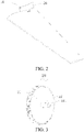
FIG. 2 is a schematic three-dimensional structural diagram of matching a wing detachment assembly with a wing of the present application. -
FIG. 3 is a schematic structural diagram of a second connecting portion from a first perspective of the present application. -
FIG. 4 is a schematic structural diagram of a second connecting portion from a second perspective of the present application. -
FIG. 5 is a schematic diagram of another structure of a second connecting portion of the present application. -
FIG. 6 is a schematic exploded structural diagram of a first connecting portion of the present application. -
FIG. 7 is a schematic structural diagram of an aerial vehicle of the present application. -
FIG. 8 is an enlarged schematic structural diagram of A inFIG. 7 . - To make the objectives, technical solutions and advantages of the present application clearer and more comprehensible, the following further describes the present application in detail with reference to the accompanying drawings and embodiments. It is to be understood that specific embodiments described herein are merely used to describe the present application, but are not intended to limit the present application. All other embodiments obtained by a person of ordinary skill in the art based on the embodiments of the present application without creative efforts shall fall within the protection scope of the present application.
- The terms such as "first", "second", "third" and "fourth" (if any) in this specification, claims and the accompanying drawings of the present application are used for distinguishing between similar objects and not necessarily used for describing any particular order or sequence. It is to be understood that the data used in such a way is interchangeable in proper cases, so that the embodiments described herein can be implemented in other orders other than the order illustrated or described herein. Moreover, the terms "include", "contain" and any other variation thereof are intended to cover the non-exclusive inclusion. For example, a process, method, system, product, or device that includes a series of steps or units is not necessarily limited to such steps or units, but may include other steps or units not expressly listed or inherent to such a process, method, product, or device.
- In addition, technical solutions of various embodiments may be combined with each other, but need to be based on the technical solutions that can be implemented by a person of ordinary skill in the art. When a combination of the technical solutions is contradictory or cannot be implemented, it should be considered that such a combination of the technical solutions does not exist and does not fall within the protection scope of the present application.
- Referring to
FIG. 1 , the present application provides awing detachment assembly 1 configured to detachably connect a wing of an aerial vehicle to a vehicle body of the aerial vehicle. Thewing detachment assembly 1 includes a first connectingportion 10 and a second connectingportion 20. The first connectingportion 10 and the second connectingportion 20 can be quickly detached and connected. Specifically, the first connectingportion 10 is threadedly connected to the second connectingportion 20. One of the first connectingportion 10 and the second connectingportion 20 is fixed on the wing and the other is fixed on the vehicle body. In this embodiment, the description is made by using an example in which the first connectingportion 10 is fixed on the vehicle body and the second connectingportion 20 is fixed on the wing. - Referring to
FIG. 2, FIG. 3 andFIG. 4 together, the second connectingportion 20 includes athumb wheel 21 and a blockingmember 22. Thethumb wheel 21 is fixedly connected to the blockingmember 22. When thethumb wheel 21 is mounted on the wing, a part of thethumb wheel 21 protrudes out of an outer portion of the wing to which thethumb wheel 21 is fixed for a user to rotate thethumb wheel 21. The blockingmember 22 is configured to prevent thethumb wheel 21 from falling out of the wing. - A threaded
hole 211 is provided on thethumb wheel 21 and is rotatably connected to the first connectingportion 10. A thread is disposed on a hole wall of the threadedhole 211. Thethumb wheel 21 is rotatably mounted on the wing. Thethumb wheel 21 is disc-shaped. An edge of thethumb wheel 21 is roughly configured and a center of thethumb wheel 21 is provided with the threadedhole 211. The threadedhole 211 is a through hole. A manner for roughly configuring the edge of thethumb wheel 21 is not limited. For example, a pattern or a strip may be disposed on the edge of thethumb wheel 21. Rough configuration of the edge of thethumb wheel 21 enables the user to easily rotate thethumb wheel 21. A diameter of thethumb wheel 21 may be set according to requirements, which is preferably set in a range of 20 mm to 80 mm. The larger the diameter of thethumb wheel 21 is, the less the force is required to rotate thethumb wheel 21. A thickness D of thethumb wheel 21 may be set according to requirements, which is preferably set in a range of 3 mm to 10 mm. The larger the thickness of thethumb wheel 21 is, the less the force is required to rotate thethumb wheel 21. - Referring to
FIG. 3 andFIG. 5 together, the blockingmember 22 is fixedly connected to one side of thethumb wheel 21. The structure of the blockingmember 22 is not limited, which can prevent thethumb wheel 21 from falling out of the wing and does not affect rotation when thethumb wheel 21 is rotated. For example, the blockingmember 22 is cylindrical. The blockingmember 22 is provided with acenter hole 221. Thecenter hole 221 may be concentric to the threadedhole 211. A diameter of thecenter hole 221 may be greater than a diameter of the threadedhole 211. The diameter of thecenter hole 221 may alternatively be equal to the diameter of the threadedhole 211. A thread may be disposed on a hole wall of thecenter hole 221 when the diameter of thecenter hole 221 is equal to the diameter of the threaded hole 211 A hole is provided on the wing, and the blockingmember 22 may be disposed in the hole. The blockingmember 22 may alternatively be a cylinder. One cylinder is disposed on one side of the threadedhole 211 and an other cylinder may be disposed in the hole provided on the wing. It is to be understood that the blockingmember 22 may be disposed on each side of thethumb wheel 21. - Referring to
FIG. 6 , the first connectingportion 10 includes a connectingplate 11 and a threadedpost 12. The connectingplate 11 is fixedly connected to the threadedpost 12. The connectingplate 11 is configured to be fixed on the vehicle body. The threadedpost 12 is configured to be threadedly connected to thethumb wheel 21 by using the threadedhole 211. It is to be understood that the accompanying drawings merely show a schematic diagram of the first connectingportion 10 and does not limit a proportional relationship between the connectingplate 11 and the threadedpost 12. - A shape of the connecting
plate 11 is not limited. For example, the connectingplate 11 is circular or quadrilateral. In this embodiment, the connectingplate 11 is fixed on an inner wall of a housing of the vehicle body. The threadedpost 12 is rotatably connected to thethumb wheel 21 through the housing of the vehicle body. The connectingplate 11 is firmly fixed on the inner wall of the housing, which is not prone to falling. The connectingplate 11 may be adhered to the inner wall of the housing of the vehicle body. An area of the connectingplate 11 is set according to requirements. When the area of the connectingplate 11 is large, a pressure on the housing of the vehicle body is relatively small. Therefore, the housing of the vehicle body is not necessarily configured to be excessively thick. It is to be understood that, the connectingplate 11 may alternatively be fixed on an outer wall of the housing of the vehicle body or embedded in the housing of the vehicle body. - A manner for fixedly connecting the connecting
plate 11 to the threadedpost 12 is not limited. The threadedpost 12 is fixed relative to the connectingplate 11 and cannot be rotated. For example, the connectingplate 11 and the threadedpost 12 may be integrally formed, which are in an interference fit. In this embodiment, a fixinghole 111 is provided on the connecting plate. An end of the threadedpost 12 is fixed in the fixinghole 111. The fixinghole 111 is configured to limit rotation of the fixinghole 111. The fixinghole 111 is non-circular. In this embodiment, the fixinghole 111 is quadrilateral. A nearby region in which thefixing hole 111 is provided on the connectingplate 11 may be thickened according to requirements, to enhance a connection strength of the connectingplate 11. - The threaded
post 12 includes abolt 121 and a fixingblock 122. An end of thebolt 121 is fixedly connected to the fixingblock 122. A thread is disposed on a surface of thebolt 121. Thebolt 121 is threadedly connected to the threadedhole 211 by using thethumb wheel 21. The fixingblock 122 is fixed in the fixinghole 111. The fixinghole 111 limits rotation of the fixingblock 122. It is to be understood that configuration of the connectingplate 11 may be omitted, and the threadedpost 12 may be fixed on the housing of the vehicle body. - During use, the connecting
plate 11 of the first connectingportion 10 is fixed on the inner wall of the housing of the vehicle body and the second connectingportion 20 is rotatably fixed on the wing. When the wing is mounted, thebolt 121 of the threadedpost 12 is aligned with the threadedhole 211 and is disposed on an edge of the threadedhole 211. The user manually rotates thethumb wheel 21 in a first rotating direction, so that the threadedpost 12 may be threadedly connected to thethumb wheel 21. If thethumb wheel 21 is rotated by specific turns, the first connectingportion 10 may be firmly connected to the second connectingportion 20, thereby fixing the wing on the vehicle body. Thethumb wheel 21 is rotated in a second rotating direction opposite to the first rotating direction, so that the first connectingportion 10 and the second connectingportion 20 may be detached from each other, thereby detaching the wing from the vehicle body. - Referring to
FIG. 7 andFIG. 8 together, the present application further provides anaerial vehicle 2. Theaerial vehicle 2 may include a flight device such as an unmanned aerial vehicle. Theaerial vehicle 2 includes avehicle body 30, awing 40 and the foregoingwing detachment assembly 1. Thewing 40 is detachably connected to thevehicle body 30 by using thewing detachment assembly 1. When thethumb wheel 21 of thewing detachment assembly 1 is mounted on the vehicle body or the wing, a part of thethumb wheel 21 protrudes out of the vehicle body or the wing to which thethumb wheel 21 is fixed. It is to be understood that, when thethumb wheel 21 is rotatably mounted on the vehicle body or the wing, a relief hole may be provided on the vehicle body or the wing, so that the threadedpost 12 may be threadedly connected to thethumb wheel 21 of thewing detachment assembly 1. - Compared with existing technologies, in the present application, the second connecting portion includes a thumb wheel, the thumb wheel being provided with a threaded hole and being configured to be rotatably mounted on the vehicle body or the wing. The first connecting portion is configured to be threadedly connected to a threaded hole of the thumb wheel, the first connecting portion and the thumb wheel being fastened or detached when the thumb wheel is rotated. In this way, the wing can be quickly mounted on the vehicle body and the wing can also be quickly detached from the vehicle body without using a dedicated detachment tool, which is easy to manually detach.
- It is to be noted that, the sequence numbers of the foregoing embodiments of the present application are merely for description purpose but are not intended to indicate the preference of the embodiments. In addition, terms "comprise", "include" or any variation thereof in this specification are intended to cover non-exclusive inclusion. Therefore, a process, a device, an article or a method including a series of elements not only include such elements, but also includes other elements not listed explicitly or includes intrinsic elements for the process, the device, the article, or the method. Unless otherwise specified, an element limited by "include a/an..." does not exclude other same elements existing in the process, the device, the article, or the method including the element.
- The foregoing descriptions are merely exemplary embodiments of the present application but are not intended to limit the patent scope of the present application. Any equivalent modifications made to the structures or processes based on the content of the specification and the accompanying drawings of the present application for direct or indirect use in other relevant technical fields shall fall within the patent protection scope of the present application.
Claims (10)
- A wing detachment assembly, configured to detachably connect a wing of an aerial vehicle to a vehicle body of the aerial vehicle, characterized in that the wing detachment assembly comprises a first connecting portion and a second connecting portion, one of the first connecting portion and the second connecting portion being fixed on the wing and the other being fixed on the vehicle body;the second connecting portion comprises a thumb wheel, the thumb wheel being provided with a threaded hole and being rotatably mounted on the vehicle body or the wing; andthe first connecting portion is threadedly connected to a threaded hole of the thumb wheel, the first connecting portion and the thumb wheel being fastened or detached when the thumb wheel is rotated.
- The wing detachment assembly according to claim 1, characterized in that the thumb wheel is disc-shaped, an edge of the thumb wheel is roughly configured and a center of the thumb wheel is provided with the threaded hole, the threaded hole being a through hole.
- The wing detachment assembly according to claim 1, characterized in that the second connecting portion further comprises a blocking member fixedly connected to one side of the thumb wheel.
- The wing detachment assembly according to claim 3, characterized in that the blocking member is cylindrical and is provided with a center hole, the center hole being concentric to the threaded hole.
- The wing detachment assembly according to claim 4, characterized in that a diameter of the center hole is greater than or equal to a diameter of the threaded hole, a thread being disposed on a hole wall of the center hole.
- The wing detachment assembly according to claim 1, characterized in that the first connecting portion comprises a threaded post, the threaded post being fixed on the wing or the vehicle body and being threadedly connected to the threaded hole.
- The wing detachment assembly according to claim 6, characterized in that the first connecting portion further comprises a connecting plate, the connecting plate being fixedly connected to the threaded post and being fixed on the vehicle body or the wing.
- The wing detachment assembly according to claim 7, characterized in that the connecting plate is fixed on an inner wall of a housing of the vehicle body or the wing, and the threaded post passes through the housing of the vehicle body or the wing to be threadedly connected to the thumb wheel.
- The wing detachment assembly according to claim 7, characterized in that the threaded post comprises a bolt and a fixing block, the bolt being fixedly connected to the fixing block, and the connecting plate is provided with a fixing hole, the fixing block being fixed in the fixing hole and the fixing hole limiting the fixing block in rotating.
- An aerial vehicle, comprising:a vehicle body;a wing; andthe wing detachment assembly according to any of claims 1 to 9, the wing being detachably connected to the vehicle body by using the wing detachment assembly and a part of the thumb wheel protruding out of the vehicle body or the wing to which the thumb wheel is fixed.
Applications Claiming Priority (2)
| Application Number | Priority Date | Filing Date | Title |
|---|---|---|---|
| CN201921474698.5U CN211618061U (en) | 2019-09-05 | 2019-09-05 | Wing disassembly assembly and aircraft |
| PCT/CN2020/123362 WO2021043336A2 (en) | 2019-09-05 | 2020-10-23 | Wing detachment assembly and aircraft |
Publications (3)
| Publication Number | Publication Date |
|---|---|
| EP4023548A2 true EP4023548A2 (en) | 2022-07-06 |
| EP4023548A4 EP4023548A4 (en) | 2023-01-25 |
| EP4023548B1 EP4023548B1 (en) | 2026-05-06 |
Family
ID=72616642
Family Applications (1)
| Application Number | Title | Priority Date | Filing Date |
|---|---|---|---|
| EP20860994.1A Active EP4023548B1 (en) | 2019-09-05 | 2020-10-23 | Wing detachment assembly and aircraft |
Country Status (4)
| Country | Link |
|---|---|
| US (1) | US12030613B2 (en) |
| EP (1) | EP4023548B1 (en) |
| CN (1) | CN211618061U (en) |
| WO (1) | WO2021043336A2 (en) |
Families Citing this family (1)
| Publication number | Priority date | Publication date | Assignee | Title |
|---|---|---|---|---|
| CN211618061U (en) * | 2019-09-05 | 2020-10-02 | 深圳市道通智能航空技术有限公司 | Wing disassembly assembly and aircraft |
Family Cites Families (22)
| Publication number | Priority date | Publication date | Assignee | Title |
|---|---|---|---|---|
| DE2531388C3 (en) * | 1975-07-14 | 1979-05-17 | Hermann Dr. 8510 Fuerth Neuhierl | Coupling device for the detachable connection of wing and elevator surface halves with the fuselage of a flight model |
| US7182666B2 (en) * | 2004-05-07 | 2007-02-27 | Hobbico, Inc. | Wing-attachment mechanism for a model airplane |
| US7237750B2 (en) * | 2004-10-29 | 2007-07-03 | L3 Communications | Autonomous, back-packable computer-controlled breakaway unmanned aerial vehicle (UAV) |
| FR2960852B1 (en) * | 2010-06-04 | 2013-04-12 | Dassault Aviat | AIRCRAFT STRUCTURAL ASSEMBLY AND ASSOCIATED ASSEMBLY METHOD |
| CN102180257B (en) * | 2011-04-15 | 2013-04-03 | 天津全华时代航天科技发展有限公司 | Modular quickly-spliced unmanned aerial vehicle |
| CN201989945U (en) * | 2011-04-15 | 2011-09-28 | 天津全华时代航天科技发展有限公司 | Modular quick-splicing type unmanned aerial vehicle |
| US8727686B2 (en) * | 2012-03-23 | 2014-05-20 | B/E Aerospace, Inc. | Device for attaching an aircraft monument |
| KR20160116734A (en) * | 2015-03-31 | 2016-10-10 | 주식회사 샘코 | UAV including telescopic wing |
| CN105366025A (en) * | 2015-11-17 | 2016-03-02 | 江西洪都航空工业集团有限责任公司 | Attachment joint for aircraft wing and fuselage of three-beam type monoplane |
| US10661882B2 (en) * | 2016-09-01 | 2020-05-26 | Horizon Hobby, LLC | Wing lock and disconnect mechanisms for a RC aircraft |
| CN207106851U (en) * | 2017-06-15 | 2018-03-16 | 深圳智航无人机有限公司 | Wing quick-disassembly structure and unmanned plane |
| CN207697985U (en) * | 2017-12-25 | 2018-08-07 | 东海县腾翔航空科技有限公司 | A kind of Novel connected wing unmanned plane |
| CN208085994U (en) * | 2018-03-07 | 2018-11-13 | 陕西金色科技有限公司 | A kind of Quick-disassembling mechanism of adjust automatically wing position |
| CN208119445U (en) * | 2018-04-19 | 2018-11-20 | 广州成至智能机器科技有限公司 | A kind of unmanned plane Quick Release carry device |
| CN208897306U (en) * | 2018-09-29 | 2019-05-24 | 四川长虹电器股份有限公司 | Unmanned aerial vehicle body and wing fast assembling-disassembling connection structure |
| CN208963299U (en) * | 2018-10-26 | 2019-06-11 | 山西恒赫贸易有限责任公司 | A kind of unmanned plane wing fast assembling disassembling structure |
| CN109572984A (en) * | 2018-11-02 | 2019-04-05 | 海空天科技股份有限公司 | A kind of fast assembly and disassembly mechanism of unmanned plane |
| CN109733588A (en) * | 2018-12-11 | 2019-05-10 | 东汉太阳能无人机技术有限公司 | A wing disassembly device |
| CN109572991B (en) * | 2018-12-28 | 2024-06-07 | 深圳市道通智能航空技术股份有限公司 | Unmanned aerial vehicle and wing assembly thereof |
| CN109720564B (en) * | 2019-02-13 | 2024-11-22 | 深圳创壹通航科技有限公司 | Fixed-wing UAV with vertical take-off and landing function and control method thereof |
| CN109808870A (en) * | 2019-04-01 | 2019-05-28 | 西北工业大学 | A kind of fast assembling disassembling structure of the vertical horizontal tail connection of unmanned plane |
| CN211618061U (en) * | 2019-09-05 | 2020-10-02 | 深圳市道通智能航空技术有限公司 | Wing disassembly assembly and aircraft |
-
2019
- 2019-09-05 CN CN201921474698.5U patent/CN211618061U/en active Active
-
2020
- 2020-10-23 WO PCT/CN2020/123362 patent/WO2021043336A2/en not_active Ceased
- 2020-10-23 EP EP20860994.1A patent/EP4023548B1/en active Active
-
2022
- 2022-03-04 US US17/653,522 patent/US12030613B2/en active Active
Also Published As
| Publication number | Publication date |
|---|---|
| WO2021043336A3 (en) | 2021-04-22 |
| CN211618061U (en) | 2020-10-02 |
| US20220234717A1 (en) | 2022-07-28 |
| EP4023548A4 (en) | 2023-01-25 |
| EP4023548B1 (en) | 2026-05-06 |
| US12030613B2 (en) | 2024-07-09 |
| WO2021043336A2 (en) | 2021-03-11 |
Similar Documents
| Publication | Publication Date | Title |
|---|---|---|
| US9027892B2 (en) | Rotating electronic display mount | |
| EP3219607B1 (en) | Driving device, propeller and propulsion system | |
| US8740171B2 (en) | Hanging system for pictures or objects | |
| EP2711563B1 (en) | Magnetic mount | |
| US12030613B2 (en) | Wing detachment assembly and aerial vehicle | |
| US6942190B1 (en) | Sucker assembly | |
| US6758626B1 (en) | Connecting device of a ceiling fan for connecting a blade to a bracket | |
| CN207676465U (en) | Combined fixing device and warning device | |
| US20220185445A1 (en) | Wing detachment assembly and aerial vehicle | |
| CN220749671U (en) | Support, camera device and security protection system | |
| US10030806B2 (en) | Fixing support and fixing module | |
| CN109195083B (en) | Loudspeaker assembly | |
| CN213505381U (en) | Low-cost carrier band dish convenient to equipment | |
| CN111765329B (en) | Three-axis rotating camera | |
| CN111721275B (en) | Marine digital duplicate magnetic compass sensor mounting bracket | |
| US5463924A (en) | Repositionable tuning peg | |
| US6677512B1 (en) | Protection device of a batter head | |
| CN221303914U (en) | Digital screen | |
| US20140291477A1 (en) | Supporting apparatus for monitor | |
| CN107295128A (en) | Fingerprint recognition case ring fixation kit, assembly method and mobile terminal | |
| CN211280757U (en) | New Cup Holder Adapter | |
| CN205751179U (en) | Warning column device | |
| CN219413198U (en) | Metal insert and connecting assembly | |
| CN116101529B (en) | A fast folding anti-loosening joint mechanism | |
| CN203698670U (en) | Quick mounting and dismounting housing of unmanned aircraft |
Legal Events
| Date | Code | Title | Description |
|---|---|---|---|
| STAA | Information on the status of an ep patent application or granted ep patent |
Free format text: STATUS: THE INTERNATIONAL PUBLICATION HAS BEEN MADE |
|
| PUAI | Public reference made under article 153(3) epc to a published international application that has entered the european phase |
Free format text: ORIGINAL CODE: 0009012 |
|
| STAA | Information on the status of an ep patent application or granted ep patent |
Free format text: STATUS: REQUEST FOR EXAMINATION WAS MADE |
|
| 17P | Request for examination filed |
Effective date: 20220328 |
|
| AK | Designated contracting states |
Kind code of ref document: A2 Designated state(s): AL AT BE BG CH CY CZ DE DK EE ES FI FR GB GR HR HU IE IS IT LI LT LU LV MC MK MT NL NO PL PT RO RS SE SI SK SM TR |
|
| DAV | Request for validation of the european patent (deleted) | ||
| DAX | Request for extension of the european patent (deleted) | ||
| A4 | Supplementary search report drawn up and despatched |
Effective date: 20230104 |
|
| RIC1 | Information provided on ipc code assigned before grant |
Ipc: A63H 27/00 20060101ALI20221222BHEP Ipc: F16B 39/28 20060101ALI20221222BHEP Ipc: B64C 3/00 20060101ALI20221222BHEP Ipc: B64C 1/00 20060101ALI20221222BHEP Ipc: B64C 1/26 20060101AFI20221222BHEP |
|
| REG | Reference to a national code |
Ref country code: DE Ref legal event code: R079 Free format text: PREVIOUS MAIN CLASS: B64C0001260000 Ipc: B64U0030120000 Ref country code: DE Ref legal event code: R079 Ref document number: 602020071831 Country of ref document: DE Free format text: PREVIOUS MAIN CLASS: B64C0001260000 Ipc: B64U0030120000 |
|
| STAA | Information on the status of an ep patent application or granted ep patent |
Free format text: STATUS: EXAMINATION IS IN PROGRESS |
|
| RIC1 | Information provided on ipc code assigned before grant |
Ipc: B64C 1/26 20060101ALI20250131BHEP Ipc: A63H 27/00 20060101ALI20250131BHEP Ipc: F16B 39/28 20060101ALI20250131BHEP Ipc: B64U 30/12 20230101AFI20250131BHEP |
|
| 17Q | First examination report despatched |
Effective date: 20250305 |
|
| GRAP | Despatch of communication of intention to grant a patent |
Free format text: ORIGINAL CODE: EPIDOSNIGR1 |
|
| STAA | Information on the status of an ep patent application or granted ep patent |
Free format text: STATUS: GRANT OF PATENT IS INTENDED |
|
| INTG | Intention to grant announced |
Effective date: 20260121 |
|
| GRAS | Grant fee paid |
Free format text: ORIGINAL CODE: EPIDOSNIGR3 |
|
| GRAA | (expected) grant |
Free format text: ORIGINAL CODE: 0009210 |
|
| STAA | Information on the status of an ep patent application or granted ep patent |
Free format text: STATUS: THE PATENT HAS BEEN GRANTED |