EP4023520B1 - Vehicle control system - Google Patents
Vehicle control system Download PDFInfo
- Publication number
- EP4023520B1 EP4023520B1 EP21218496.4A EP21218496A EP4023520B1 EP 4023520 B1 EP4023520 B1 EP 4023520B1 EP 21218496 A EP21218496 A EP 21218496A EP 4023520 B1 EP4023520 B1 EP 4023520B1
- Authority
- EP
- European Patent Office
- Prior art keywords
- vehicle
- path
- path planning
- ranking
- trajectory
- Prior art date
- Legal status (The legal status is an assumption and is not a legal conclusion. Google has not performed a legal analysis and makes no representation as to the accuracy of the status listed.)
- Active
Links
Images


Classifications
-
- B—PERFORMING OPERATIONS; TRANSPORTING
- B60—VEHICLES IN GENERAL
- B60W—CONJOINT CONTROL OF VEHICLE SUB-UNITS OF DIFFERENT TYPE OR DIFFERENT FUNCTION; CONTROL SYSTEMS SPECIALLY ADAPTED FOR HYBRID VEHICLES; ROAD VEHICLE DRIVE CONTROL SYSTEMS FOR PURPOSES NOT RELATED TO THE CONTROL OF A PARTICULAR SUB-UNIT
- B60W30/00—Purposes of road vehicle drive control systems not related to the control of a particular sub-unit, e.g. of systems using conjoint control of vehicle sub-units
- B60W30/10—Path keeping
-
- B—PERFORMING OPERATIONS; TRANSPORTING
- B60—VEHICLES IN GENERAL
- B60W—CONJOINT CONTROL OF VEHICLE SUB-UNITS OF DIFFERENT TYPE OR DIFFERENT FUNCTION; CONTROL SYSTEMS SPECIALLY ADAPTED FOR HYBRID VEHICLES; ROAD VEHICLE DRIVE CONTROL SYSTEMS FOR PURPOSES NOT RELATED TO THE CONTROL OF A PARTICULAR SUB-UNIT
- B60W30/00—Purposes of road vehicle drive control systems not related to the control of a particular sub-unit, e.g. of systems using conjoint control of vehicle sub-units
- B60W30/08—Active safety systems predicting or avoiding probable or impending collision or attempting to minimise its consequences
- B60W30/095—Predicting travel path or likelihood of collision
-
- B—PERFORMING OPERATIONS; TRANSPORTING
- B60—VEHICLES IN GENERAL
- B60W—CONJOINT CONTROL OF VEHICLE SUB-UNITS OF DIFFERENT TYPE OR DIFFERENT FUNCTION; CONTROL SYSTEMS SPECIALLY ADAPTED FOR HYBRID VEHICLES; ROAD VEHICLE DRIVE CONTROL SYSTEMS FOR PURPOSES NOT RELATED TO THE CONTROL OF A PARTICULAR SUB-UNIT
- B60W30/00—Purposes of road vehicle drive control systems not related to the control of a particular sub-unit, e.g. of systems using conjoint control of vehicle sub-units
- B60W30/10—Path keeping
- B60W30/12—Lane keeping
-
- B—PERFORMING OPERATIONS; TRANSPORTING
- B60—VEHICLES IN GENERAL
- B60W—CONJOINT CONTROL OF VEHICLE SUB-UNITS OF DIFFERENT TYPE OR DIFFERENT FUNCTION; CONTROL SYSTEMS SPECIALLY ADAPTED FOR HYBRID VEHICLES; ROAD VEHICLE DRIVE CONTROL SYSTEMS FOR PURPOSES NOT RELATED TO THE CONTROL OF A PARTICULAR SUB-UNIT
- B60W60/00—Drive control systems specially adapted for autonomous road vehicles
- B60W60/001—Planning or execution of driving tasks
- B60W60/0011—Planning or execution of driving tasks involving control alternatives for a single driving scenario, e.g. planning several paths to avoid obstacles
-
- B—PERFORMING OPERATIONS; TRANSPORTING
- B62—LAND VEHICLES FOR TRAVELLING OTHERWISE THAN ON RAILS
- B62D—MOTOR VEHICLES; TRAILERS
- B62D15/00—Steering not otherwise provided for
- B62D15/02—Steering position indicators ; Steering position determination; Steering aids
- B62D15/025—Active steering aids, e.g. helping the driver by actively influencing the steering system after environment evaluation
- B62D15/0255—Automatic changing of lane, e.g. for passing another vehicle
-
- G—PHYSICS
- G05—CONTROLLING; REGULATING
- G05D—SYSTEMS FOR CONTROLLING OR REGULATING NON-ELECTRIC VARIABLES
- G05D1/00—Control of position, course, altitude or attitude of land, water, air or space vehicles, e.g. using automatic pilots
- G05D1/0088—Control of position, course, altitude or attitude of land, water, air or space vehicles, e.g. using automatic pilots characterized by the autonomous decision making process, e.g. artificial intelligence, predefined behaviours
-
- B—PERFORMING OPERATIONS; TRANSPORTING
- B60—VEHICLES IN GENERAL
- B60W—CONJOINT CONTROL OF VEHICLE SUB-UNITS OF DIFFERENT TYPE OR DIFFERENT FUNCTION; CONTROL SYSTEMS SPECIALLY ADAPTED FOR HYBRID VEHICLES; ROAD VEHICLE DRIVE CONTROL SYSTEMS FOR PURPOSES NOT RELATED TO THE CONTROL OF A PARTICULAR SUB-UNIT
- B60W50/00—Details of control systems for road vehicle drive control not related to the control of a particular sub-unit, e.g. process diagnostic or vehicle driver interfaces
- B60W2050/0001—Details of the control system
- B60W2050/0002—Automatic control, details of type of controller or control system architecture
- B60W2050/0004—In digital systems, e.g. discrete-time systems involving sampling
- B60W2050/0006—Digital architecture hierarchy
-
- B—PERFORMING OPERATIONS; TRANSPORTING
- B60—VEHICLES IN GENERAL
- B60W—CONJOINT CONTROL OF VEHICLE SUB-UNITS OF DIFFERENT TYPE OR DIFFERENT FUNCTION; CONTROL SYSTEMS SPECIALLY ADAPTED FOR HYBRID VEHICLES; ROAD VEHICLE DRIVE CONTROL SYSTEMS FOR PURPOSES NOT RELATED TO THE CONTROL OF A PARTICULAR SUB-UNIT
- B60W50/00—Details of control systems for road vehicle drive control not related to the control of a particular sub-unit, e.g. process diagnostic or vehicle driver interfaces
- B60W2050/0062—Adapting control system settings
- B60W2050/0075—Automatic parameter input, automatic initialising or calibrating means
- B60W2050/0095—Automatic control mode change
- B60W2050/0096—Control during transition between modes
-
- B—PERFORMING OPERATIONS; TRANSPORTING
- B60—VEHICLES IN GENERAL
- B60W—CONJOINT CONTROL OF VEHICLE SUB-UNITS OF DIFFERENT TYPE OR DIFFERENT FUNCTION; CONTROL SYSTEMS SPECIALLY ADAPTED FOR HYBRID VEHICLES; ROAD VEHICLE DRIVE CONTROL SYSTEMS FOR PURPOSES NOT RELATED TO THE CONTROL OF A PARTICULAR SUB-UNIT
- B60W2552/00—Input parameters relating to infrastructure
- B60W2552/05—Type of road, e.g. motorways, local streets, paved or unpaved roads
-
- B—PERFORMING OPERATIONS; TRANSPORTING
- B60—VEHICLES IN GENERAL
- B60W—CONJOINT CONTROL OF VEHICLE SUB-UNITS OF DIFFERENT TYPE OR DIFFERENT FUNCTION; CONTROL SYSTEMS SPECIALLY ADAPTED FOR HYBRID VEHICLES; ROAD VEHICLE DRIVE CONTROL SYSTEMS FOR PURPOSES NOT RELATED TO THE CONTROL OF A PARTICULAR SUB-UNIT
- B60W2556/00—Input parameters relating to data
- B60W2556/45—External transmission of data to or from the vehicle
- B60W2556/50—External transmission of data to or from the vehicle of positioning data, e.g. GPS [Global Positioning System] data
Definitions
- the present disclosure relates to a method of controlling a vehicle. Aspects of the invention relate to a method of controlling the vehicle, to a control system, to a computer program, to a computer-readable data carrier and to a vehicle.
- Contemporary vehicles are known that feature Advanced Driver Assistance Systems (ADAS) that assist the driver in a variety of driving scenarios by providing a level of automated control of the vehicle.
- ADAS Advanced Driver Assistance Systems
- path planning systems are known for determining a path, or route, for a vehicle to follow in certain driving conditions
- electronically controlled steering systems are known for controlling the driving direction, or steering, of the vehicle, based on the determined path.
- a lane keeping assist system is a well-known path planning system that determines a path for the vehicle to follow based on lane markings detected on the surface of a roadway ahead of the vehicle.
- the lane keeping assist system outputs the path to an electronically controlled steering system and the electronically controlled steering system determines steering inputs based on the path to control the trajectory, or driving direction, of the vehicle along the roadway.
- a challenge with such path planning systems is to be able to reliably determine a path for the vehicle to follow in different driving conditions.
- a lane keeping assist system may be unable to determine a reliable path for the vehicle to follow in the absence of lane markings on the surface of the roadway.
- US 2020/331495 A1 discloses a path planning method for an autonomous vehicle including ranking algorithms of path planning.
- a method of controlling a trajectory of a vehicle that includes a plurality of path planning systems.
- the method comprises: determining an activation state of each of the path planning systems; selecting a first one of the active path planning systems for controlling the trajectory of the vehicle; controlling the trajectory of the vehicle based on a first path determined by the selected path planning system; checking if a condition for switching to another one of the path planning systems is triggered; and in dependence on the switching condition being triggered: selecting a second one of the active path planning systems for controlling the trajectory of the vehicle; and switching from controlling the trajectory of the vehicle based on the first path to controlling the trajectory of the vehicle based on a second path determined by the second one of the path planning systems.
- the method may be configured to control the trajectory of the vehicle according to a path provided by a path planning system that is optimal for the respective driving conditions and to switch to the second path, provided by another path planning system, in dependence on the switching condition, e.g. when the vehicle enters a new roadway.
- the activation state may, for example, be one of an active state, a partially active state, and/or an inactive state.
- the activation state of each of the path planning systems is determined based on: an ability of that path planning system to determine a path for the vehicle to follow; and an ability of that path planning system to locate the vehicle on that path. In this manner, a path planning system may become active when the vehicle enters a new roadway where it is possible for the path planning system to localise the vehicle and determine a path along the roadway for the vehicle.
- the selection of the first one of the active path planning systems is based on a ranking index that includes a relative ranking of the path planning systems.
- the relative ranking may, for example, be indicative of the relative robustness or reliability of the path planning system.
- the method further comprises selecting the ranking index from a plurality of ranking indexes, prior to selecting the first one of the active path planning systems, wherein each ranking index is associated with a corresponding geographical location, and optionally with a roadway classification.
- the selection of the ranking index is based on: a geographical location of the vehicle; and optionally on a classification of the roadway ahead of the vehicle.
- the method further comprises selecting another ranking index from the plurality of ranking indexes, prior to checking if the condition for switching to another one of the path planning systems is triggered, in dependence on the geographical location of the vehicle and/or the classification of the roadway ahead of the vehicle changing.
- the method may select a ranking index corresponding to the location of the vehicle so that the subsequent selection of the applicable path planning system is made based on preferences that correspond to the current location.
- the switching condition is dependent on the activation states of the path planning systems.
- the switching condition may trigger the switching condition to switch to the path produced by that path planning system, for example.
- the switching condition may also be dependent on the relative ranking of the path planning systems according to the ranking index. In this manner, if the ranking index changes, for example based on the location of the vehicle, then another path planning system may be preferred producing the switching condition.
- a computer program comprising instructions which, when the program is executed by a computer, cause the computer to carry out the method described in a previous aspect of the invention.
- a control system for controlling a trajectory of a vehicle.
- the control system comprises one or more controllers configured to: receive one or more signals indicative of an activation state of each one of a plurality of path planning systems of the vehicle; select a first one of the active path planning systems for controlling the trajectory of the vehicle; output a first path, received from the selected path planning system, for controlling the trajectory of the vehicle; select a second one of the active path planning systems for controlling the trajectory of the vehicle in dependence on detecting a switching condition being satisfied; and output a second path, received from the second one of the path planning systems, for controlling the trajectory of the vehicle.
- the one or more controllers may, for example, be configured to detect that the switching condition is satisfied in dependence on the activation state of the first and/or second path planning systems.
- the activation state of each of the path planning systems is determined based on: an ability of that path planning system to determine a path for the vehicle to follow; and an ability of that path planning system to locate the vehicle on that path.
- the one or more controllers are further configured to: receive one or more signals indicative of a geographical location of the vehicle and optionally a classification of the roadway ahead of the vehicle; and select the ranking index from a plurality of ranking indexes, each ranking index being associated with a corresponding geographical location and optionally roadway classification, based on the geographical location of the vehicle and optionally the classification of the roadway ahead of the vehicle.
- a vehicle comprising control system as described in a further previous aspect of the invention.
- Embodiments of the invention relate to a method of controlling the driving direction of a vehicle that includes a plurality of path planning systems.
- the plurality of path planning systems determine respective paths for the vehicle to follow based on different inputs and/or inputs from different sources. This provides enhanced fail-safety in the absence of suitable inputs for one of the path planning systems.
- a lane keeping system may be unable to determine a path for the vehicle to follow and an alternative path planning system may be used instead.
- the plurality of path planning systems are able to reliably determine a path for the vehicle to follow in a variety of driving conditions.
- the method determines which of the plurality of path planning systems are active and selectively operates a preferred one of the active path planning systems to determine a path for the vehicle to follow.
- 'active it is intended to mean that the path planning system is able to determine a path for the vehicle to follow and to locate the vehicle on that path.
- the determined path is output to an electrically controlled steering system that controls the driving direction of the vehicle accordingly.
- the selected path planning system effectively controls the driving direction of the vehicle.
- the preferred path planning system may change.
- the activation states of the path planning systems and/or the relative preferences of the path planning systems may change.
- the method may select another active path planning system to operate and determine an alternative path for the vehicle to follow.
- a preferred path for the vehicle to follow can be provided in different driving conditions.
- a challenge with this method is that the switch from controlling the steering of the vehicle based on the current path to controlling the steering of the vehicle based on the alternative path can cause the electronically controlled steering system to impart a large change in the driving direction of the vehicle.
- the change in driving direction may destabilise the vehicle or otherwise affect the comfort of the vehicle occupants.
- embodiments of the invention also relate to a method of switching from controlling the trajectory of the vehicle based on the current (first) path to controlling the trajectory of the vehicle based on the alternative (second) path.
- the invention is configured to make this switch in a controlled manner that may even be imperceptible to any vehicle occupants.
- the method determines: i) a forecast trajectory of the vehicle based on the second path; ii) a current trajectory of the vehicle based on the first path; and iii) an offset between the forecast trajectory and the current trajectory of the vehicle, which is compared to a threshold offset.
- This comparison is made to determine whether the offset between the forecast trajectory and the current trajectory is less than or equal to a threshold offset, thereby satisfying a threshold of correspondence to the current trajectory.
- the threshold offset may be configured to ensure that the changes in driving direction are within limits of passenger comfort.
- the second path may be output to the electronically controlled steering system to switch to determining the driving direction of the vehicle based on the second path.
- the second path may be output to the electronically controlled steering system if the forecast trajectory changes the steering angle by less than 10 degrees relative to the current trajectory, and more preferably by less than 5 degrees relative to the current trajectory.
- the electronically controlled steering system may continue to steer the vehicle based on the first path and the switch may be postponed until there is sufficient correspondence between the first and second paths.
- the threshold offset ensures that relatively small changes in driving direction are imparted when switching between the path planning systems.
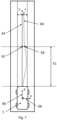
- Figure 1 schematically illustrates an example vehicle 1 featuring an electronically controlled steering system 2 and a control system 4 for controlling the driving direction of the vehicle 1 in accordance with an embodiment of the present invention.
- the electronically controlled steering system 2 is configured to receive a path for the vehicle 1 to follow, from the control system 4, and to control the driving direction of the vehicle 1 based on that path.
- the electronically controlled steering system 2 may take any suitable form known in the art and may, for example, include: a steering mechanism configured to control the driving direction of the vehicle 1; a sensor system configured to detect the driving direction of the vehicle 1; an actuation system configured to control the steering system; and a controller configured to control the actuation system based on the received path.
- the electronically controlled steering system 2 is not described in detail here to avoid obscuring the invention.
- a commercially available BOSCH ® Electric Power Steering System may be suitable for providing this form of steering control.
- control system 4 will now be described in more detail with reference to Figure 2 , which schematically illustrates an example of the control system 4 in accordance with an embodiment of the present invention.
- control system 4 includes a plurality of path planning systems 6 and a path control module 8.
- Each of the plurality of path planning systems 6 is configured to determine a respective path for the vehicle 1 to follow along a roadway based on a different sensory input and/or one or more inputs from different systems. This increases the likelihood that one of the path planning systems will be able to determine a path along a given roadway.
- each path planning system operates in one of an active state, a partially active state or an inactive state.
- the path planning system In the active state, the path planning system is able to determine a path for the vehicle to follow and to locate the vehicle on that path.
- the path planning system In the partially-active state, the path planning system is able to determine a partial or incomplete path for the vehicle to follow and to locate the vehicle on that path.
- the path planning system In the inactive state, the path planning system is unable to determine a path for the vehicle to follow or otherwise unable to locate the vehicle on that path.
- the relative completeness of the path, and hence the state of activation of the path planning system may depend on the speed of travel of the vehicle 1.
- the path planning system may be able to determine a partial path for the vehicle 1 to follow that extends 50 m ahead of the vehicle when travelling at 48 km/h (30 mph ), but a path extending 50 m ahead of the vehicle 1 may be insufficient for the vehicle 1 to follow when travelling at 113 km/h (70 mph).
- the plurality of path planning systems 6 includes a first path planning system 10, a second path planning system 12 and a third path planning system 14.
- the first path planning system 10 takes the form of a lane keeping assist system configured to determine a first path for the vehicle 1 to follow based on inputs related to the detection of lane markings on the surface of the roadway.
- the activation of the first path planning system 10 is therefore dependent on one or more sensors (not shown) of the vehicle 1 being able to detect such lane markings on the surface of the roadway in order to determine the first path.
- the second path planning system 12 takes the form of a visual simultaneous localisation and mapping (VSLAM) system configured to determine a second path for the vehicle 1 to follow by recognising the roadway that the vehicle 1 is travelling along.
- VSLAM visual simultaneous localisation and mapping
- the third path planning system 14 takes the form of a global positioning system (GPS) configured to determine a third path for the vehicle 1 to follow based on GPS signals related to the geographical location of the vehicle 1.
- GPS global positioning system
- the activation of the third path planning system 14 is therefore dependent on the vehicle 1 being able to receive corresponding GPS signals from a transmitter, such as a GPS satellite.
- the plurality of path planning systems 6 may include any other suitable path planning systems that are known in the art, such as a LIDAR based path planning system, and may include any multitude of path planning systems for this purpose.
- each of the path planning systems may be configured to output a respective path comprising a series of target positions for the vehicle 1 to pass through.
- each path may comprise a series of trajectory points 16a-e arranged ahead of the vehicle 1 that define a path 18 for the vehicle 1 to follow.
- the electronically controlled steering system 2 may receive a respective path 18 and determine a steering input or driving direction of the vehicle 1 based on the relative position of one or more of the trajectory points 16a-e to the vehicle 1.
- the steering input may be negligible.
- the electronically controlled steering system 2 may determine a change in driving direction, or steering input, configured to redirect the vehicle 1 towards that trajectory point 16a-e.
- the electronically controlled steering system 2 may continuously or periodically determine steering inputs configured to control the driving direction of the vehicle 1 in accordance with the path 18 received from the plurality of path planning systems 6.
- control system 4 includes a multitude of path planning systems and so the path control module 8 is configured to selectively operate one of the active path planning systems to output a path 18 to the electronically controlled steering system 2 for the vehicle 1 to follow.
- the path control module 8 is configured to select one of the active path planning systems based on a ranking index that includes a relative ranking for each of the plurality of path planning systems 10, 12, 14.
- the ranking index may be stored in a memory storage device of the path control module 8, for example.
- the path control module 8 includes a plurality of ranking indexes associated with different geographical locations of the vehicle 1 and optionally different classifications of the roadway that the vehicle 1 is traversing.
- roadway classifications such as a highway, a controlled-access highway, a limited access highway, a local road, or any other suitable roadway classification.
- the path control module 8 is configured to select one of the ranking indexes in dependence on the geographical location of the vehicle 1 and alternatively the classification of the roadway.
- the geo-location of the vehicle 1 and/or the classification of may be indicated to the path control module 8 by one or more signals received from the plurality of path planning systems 10, 12, 14 and/or one or more other vehicle systems (not shown), for example.
- the vehicle 1 may move from a geographical zone and optionally roadway associated with a first ranking index to a geographical zone and optionally roadway associated with a second ranking index and the path control module 8 re-selects the ranking index upon entering the second roadway. Consequently, the path control module 8 may determine that a different path planning system 10, 12, 14 is preferred based on the second ranking index.
- the plurality of ranking indexes may be stored in a memory storage device of the path control module 8, for example.
- the path control module 8 is configured to operate the selected path planning system 10, 12, 14 so as to output the respective path 18 to the electronically controlled steering system 2, which controls the driving direction of the vehicle 1 accordingly.
- the path control module 8 is advantageously further configured to selectively operate an alternative one of the plurality of path planning systems 10, 12, 14 to output its respective path 18 to the electronically controlled steering system 2 in dependence on a switching condition being triggered.
- the switching condition indicates that an alternative one of the plurality of path planning systems 10, 12, 14 is preferred to the selected path planning system.
- the switching condition may be triggered in dependence on one or more of: the geo-graphical location of the vehicle 1; a change of the activation state of one or more of the path planning systems; and/or a change in the ranking index.
- the inputs to the path planning systems 10, 12, 14 may be affected, changing the activation states of one or more of the path planning systems 10, 12, 14. This may trigger the switching condition if a higher ranking path planning system becomes active or the currently selected path planning system changes to a partially-active state (only able to determine a partial path for the vehicle 1 to follow).
- the path control module 8 may select another one of the active path planning systems to operate.
- the path control module 8 may also be configured to make the second selection, or reselection, based on the ranking index.
- the path control module 8 may be configured to re-select the ranking index from the plurality of ranking indexes in dependence on the switching condition being triggered and to select the alternative path planning system to operate based on the selected ranking index.
- the ranking index may be re-selected based on the geo-location of the vehicle 1 and/or the classification of the roadway ahead of the vehicle 1, for example.
- the switching condition may be associated with an alternative one of the path planning systems 10, 12, 14 and the path control module 8 may be configured to select that path planning system in response to the switching condition being triggered.
- the path control module 8 is configured to manage the switching process so as to maximise the stability of the driving direction of the vehicle 1. For example, when switching between the path planning systems 10, 12, 14, the path control module 8 is configured such that the alternative path is only output to the electronically controlled steering system 2 in dependence on an offset between the current path and the alternative path being less than or equal to a threshold offset.
- the alternative path must satisfy a threshold of correspondence to the current path for the path control module 8 to execute the switch, as shall become clear in the following description.
- the path control module 8 may include one or more controllers and each controller may comprise a control unit or computational device having one or more electronic processors.
- a set of instructions may be provided that cause the one or more controllers, or control units, to implement a control method, such as the control methods described herein, when executed.
- the set of instructions may be embedded in one or more of the electronic processors.
- the set of instructions may be provided as software to be executed by one or more of the electronic processors.
- the set of instructions may be embedded in a computer-readable storage medium (e.g., a non-transitory computer-readable storage medium) that may comprise any mechanism for storing information in a form readable by a machine or electronic processors/computational device.
- a computer-readable storage medium e.g., a non-transitory computer-readable storage medium
- This may include, without limitation: a magnetic storage medium (e.g., floppy diskette); optical storage medium (e.g., CD-ROM); magneto optical storage medium; read only memory (ROM); random access memory (RAM); erasable programmable memory (e.g., EPROM and EEPROM); flash memory; or electrical or other types of medium for storing such information/instructions.
- control system 4 shall now be described with additional reference to Figures 4 to 9 .
- FIG. 4 illustrates an example method 20 of operating the control system 4 in accordance with an embodiment of the invention.
- the vehicle 1 may have entered a first roadway 50, as shown in Figure 5 , and the control system 4 may be operated to control the driving direction of the vehicle 1 towards a target destination 52.
- the first roadway 50 may be a highway with clear and detectable lane markings on the road surface, for example.
- the path control module 8 determines the activation states of the plurality of path planning systems 10, 12, 14. In particular, the path control module 8 may determine whether each path planning system is operating in an active, partially-active or inactive state based on the ability of that path planning system to: i) determine a respective path for the vehicle 1 to follow along the first roadway 50; and ii) locate the vehicle 1 on that path.
- the path control module 8 may determine whether the first path planning system 10 is able to sufficiently detect lane markings on the first roadway 50 to form a first path for the vehicle 1 to follow along the first roadway 50.
- the path control module 8 may also determine whether the second path planning system 12 is able to recognise the first roadway 50 and to retrieve a pre-determined second path, associated with the first roadway 50, for the vehicle 1 to follow.
- the path control module 8 may also determine whether the third path planning system 14 is able to receive GPS signals comprising sufficient information to determine a geo-location of the vehicle 1 on the first roadway 50 and a corresponding third path for the vehicle 1 to follow along the first roadway 50.
- the first roadway 50 may not correspond to a recognised roadway and therefore the second path planning system 12 may be considered inactive at step 22.
- the first and third path planning systems 10, 14 may be considered active due to the availability of GPS signals and the ability of the vehicle 1 to detect lane marking on the road surface of the highway.
- step 24 the path control module 8 selects an active path planning system to operate in order to produce the path for the vehicle 1 to follow along the first roadway 50.
- the path control module 8 may access the memory storage device (not shown) of the path control module 8 and select a ranking index that provides a relative ranking for each of the first, second and third path planning systems 10, 12, 14.
- the path control module 8 selects the ranking index from a plurality of ranking indexes based on the geographical location of the vehicle 1, which corresponds to a position on the first roadway 50.
- the path control module 8 selects a first ranking index based on the geo-location of the vehicle 1 when the vehicle 1 is driving on the first roadway 50
- the first path planning system 10 may have the highest rank on the first ranking index, whilst the second path planning system 12 may have the second highest rank and the third path planning system 14 may have the third highest rank.
- the relative ranking may be determined on the basis of a perceived comfort of the vehicle occupants for a typical path provided by each path planning system, for example.
- the path control module 8 may therefore select the first path planning system 10, in step 24, as the highest ranking active path planning system and operate the first path planning system 10 to determine a first path for the vehicle 1 to follow along the first roadway 50.
- step 26 the control system 4 controls the driving direction of the vehicle 1 based on the first path and steers the vehicle 1 along the first roadway 50.
- the path control module 8 may control the first path planning system 10 so as to output the first path to the electronically controlled steering system 2 and the electronically controlled steering system 2 may control the driving direction of the vehicle 1 based on that path, steering the vehicle 1 towards the target destination 52.
- step 28 the path control module 8 checks whether the switching condition is triggered as the vehicle 1 travels towards the target destination.
- the path control module 8 may monitor the geo-location of the vehicle 1 and/or the activation states of the plurality of path planning systems 10, 12, 14.
- control system 4 continues to control the driving direction of the vehicle 1 along the first path, and proceeds towards the target destination 52, whilst repeating step 28.
- the path control module 8 proceeds to re-select the path planning system in step 30.
- the vehicle 1 may leave the first roadway 50 and approach a second roadway 54, as shown in Figure 5 .
- the second roadway 54 may be a recognised local roadway that lacks clearly defined lane markings along a portion of the road surface.
- the second path planning system 12 may change from an inactive state to an active state as the second roadway 54 is recognised and the first path planning system 10 may change from an active state to a partially-active state due to the lack of lane markings.
- the change in the geo-location of the vehicle 1 and/or the change in the activation states of the first and second path planning systems 10, 12 may trigger the switching condition, in step 28.
- the path control module 8 may select another active path planning system to operate in order to produce a path for the vehicle 1 to follow along the second roadway 54.
- the path control module 8 may access the ranking index again or select another ranking index corresponding to the geo-location of the vehicle 1 and/or the classification of the second roadway 54, for example.
- the path control module 8 may therefore select the second ranking index and proceed to select the second path planning system 12, in step 30, accordingly.
- the second path planning system 12 is selected because the first path planning system 10 has changed to a partially-active state, whilst the second path planning system 12 is in an active state and, in any case, higher ranking than the first path planning system 10.
- step 32 the control system 4 switches from controlling the driving direction of the vehicle 1 based on the first path to controlling the driving direction of the vehicle 1 based on the second path, whilst driving the vehicle 1 along the second roadway 54.
- the path control module 8 may compare a forecast trajectory of the vehicle 1, based on the second path, to a current trajectory of the vehicle 1, based on the first path.
- the path control module 8 may conditionally output the second path to the electronically controlled steering system 2 when there is sufficient correspondence between the first and second paths, as will be described in more detail with reference to the following sub-steps 34 to 40, shown in Figure 6 .
- the path control module 8 continues to operate the first path planning system 10 to determine the first path, which is output to the electronically controlled steering system 2 for controlling the driving direction of the vehicle 1.
- the path control module 8 determines a forecast trajectory, or driving direction, for the vehicle 1 based on the second path and the path control module 8 determines an offset between the forecast trajectory and a current trajectory, based on the first path, in sub-step 36.
- the path control module 8 compares the offset to a threshold offset, in sub-step 38.
- the forecast trajectory is defined by a first point 58, arranged ahead of the vehicle 1, through which the vehicle 1 would pass if the vehicle 1 were steered along the second path 60, as shown in Figure 7 .
- the current trajectory may be defined by a second point 62, arranged the same distance ahead of the vehicle 1 as the first point 58, through which the vehicle 1 will pass if the vehicle 1 is steered along the first path 64, as also shown in Figure 7 .
- the offset between the forecast trajectory and the current trajectory takes the form of a lateral distance between the first and second points 58, 62. Accordingly, the threshold offset takes the form of a maximum distance between the first and second points 58, 62.
- the path control module 8 may determine the forecast trajectory as a first point 58 on the second path 60 having co-ordinates X1, Y1, in sub-step 35.
- X1 may be a pre-determined distance ahead of the vehicle 1 along a longitudinal axis 66 of the vehicle 1
- Y1 may be a transverse distance along a perpendicular axis 68 to the longitudinal axis 56.
- the path control module 8 may determine the current trajectory as a second point 62 on the first path 64 having co-ordinates X1, Y2, where Y2 is a second transverse distance along the perpendicular axis 58.
- the path control module 8 may determine the forecast trajectory as a first steering angle 70 relative to the longitudinal axis 66 of the vehicle 1.
- the current trajectory may be directed along the longitudinal axis 66 of the vehicle 1 or the path control module 8 may otherwise determine the current trajectory as a second steering angle 72 relative to the longitudinal axis 66 of the vehicle 1.
- the path control module 8 may determine the first steering angle 70, in sub-step 34, based on the relative direction of one or more of the series of trajectory points 60a-c forming the second path 60 to the longitudinal axis 66 of the vehicle 1.
- the path control module 8 may determine the offset between the forecast trajectory and the current trajectory based on the angle of deviation between the first and second steering angles 70, 72, in sub-step 36.
- the threshold offset may take the form of a maximum angle of deviation 74 from the second steering angle 72 in a first and/or second direction, as shown in Figure 9 .
- the threshold of correspondence may be satisfied if the offset is less than the maximum angle of deviation from the current trajectory.
- the threshold offset may depend on the path planning systems that the control system 4 is switching between.
- the threshold offset may take a first value when switching from the first path planning system 10 to the second path planning system 12, but the threshold offset may take a larger second value when switching from the first path planning system 10 to the third path planning system 14, for example.
- control system 4 continues to control the driving direction of the vehicle 1 based on the first path and repeats sub-steps 34 to 38 until the offset between the forecast trajectory and the current trajectory falls below or equal to the threshold offset.
- the electronically controlled steering system 2 continues to steer the vehicle 1 based on the first path until the change in driving direction caused by steering the vehicle 1 based on the second path is sufficiently small, e.g. imperceptible to a vehicle occupant.
- control system 4 controls the driving direction of the vehicle 1 based on the second path (determined by the second path planning system 12), in sub-step 40.
- the path control module 8 operates the second path planning system 12 to determine the second path based on the recognised roadway and to output the second path to the electronically controlled steering system 2. Accordingly, the electronically controlled steering system 2 controls the driving direction of the vehicle 1 to steer the vehicle 1 along the second path.
- the vehicle 1 proceeds to drive along the second roadway 54 according to the second path, and continues to check for further switching conditions being triggered, in step 28, as the vehicle 1 drives towards the target destination.
- control system 4 may selectively operate the first or third path planning systems to determine a respective path for the vehicle to follow substantially as described in in steps 28 and 30.
- the invention provides for automated steering of the vehicle 1 towards a target destination 52 using a plurality of path planning systems 10, 12, 14 that provide fail-safe operation in the event that inputs to one of the path planning systems are intermittently available.
Landscapes
- Engineering & Computer Science (AREA)
- Mechanical Engineering (AREA)
- Automation & Control Theory (AREA)
- Transportation (AREA)
- Evolutionary Computation (AREA)
- Game Theory and Decision Science (AREA)
- Human Computer Interaction (AREA)
- Business, Economics & Management (AREA)
- Health & Medical Sciences (AREA)
- Artificial Intelligence (AREA)
- Chemical & Material Sciences (AREA)
- Combustion & Propulsion (AREA)
- Medical Informatics (AREA)
- Aviation & Aerospace Engineering (AREA)
- Radar, Positioning & Navigation (AREA)
- Remote Sensing (AREA)
- Physics & Mathematics (AREA)
- General Physics & Mathematics (AREA)
- Steering Control In Accordance With Driving Conditions (AREA)
- Control Of Driving Devices And Active Controlling Of Vehicle (AREA)
Description
- The present disclosure relates to a method of controlling a vehicle. Aspects of the invention relate to a method of controlling the vehicle, to a control system, to a computer program, to a computer-readable data carrier and to a vehicle.
- Contemporary vehicles are known that feature Advanced Driver Assistance Systems (ADAS) that assist the driver in a variety of driving scenarios by providing a level of automated control of the vehicle. For example, path planning systems are known for determining a path, or route, for a vehicle to follow in certain driving conditions and electronically controlled steering systems are known for controlling the driving direction, or steering, of the vehicle, based on the determined path.
- By way of example, a lane keeping assist system is a well-known path planning system that determines a path for the vehicle to follow based on lane markings detected on the surface of a roadway ahead of the vehicle. The lane keeping assist system outputs the path to an electronically controlled steering system and the electronically controlled steering system determines steering inputs based on the path to control the trajectory, or driving direction, of the vehicle along the roadway.
- Such path planning systems are increasingly commonplace due to the technological developments in sensory technologies and the improved capabilities of on-board processing devices.
- However, a challenge with such path planning systems is to be able to reliably determine a path for the vehicle to follow in different driving conditions. For example, a lane keeping assist system may be unable to determine a reliable path for the vehicle to follow in the absence of lane markings on the surface of the roadway.
-
US 2020/331495 A1 discloses a path planning method for an autonomous vehicle including ranking algorithms of path planning. - It is an aim of the present invention to address one or more of the disadvantages associated with the prior art.
- According to an aspect of the invention there is provided a method of controlling a trajectory of a vehicle that includes a plurality of path planning systems. The method comprises: determining an activation state of each of the path planning systems; selecting a first one of the active path planning systems for controlling the trajectory of the vehicle; controlling the trajectory of the vehicle based on a first path determined by the selected path planning system; checking if a condition for switching to another one of the path planning systems is triggered; and in dependence on the switching condition being triggered: selecting a second one of the active path planning systems for controlling the trajectory of the vehicle; and switching from controlling the trajectory of the vehicle based on the first path to controlling the trajectory of the vehicle based on a second path determined by the second one of the path planning systems.
- In this manner, the method may be configured to control the trajectory of the vehicle according to a path provided by a path planning system that is optimal for the respective driving conditions and to switch to the second path, provided by another path planning system, in dependence on the switching condition, e.g. when the vehicle enters a new roadway.
- The activation state may, for example, be one of an active state, a partially active state, and/or an inactive state. Optionally, the activation state of each of the path planning systems is determined based on: an ability of that path planning system to determine a path for the vehicle to follow; and an ability of that path planning system to locate the vehicle on that path. In this manner, a path planning system may become active when the vehicle enters a new roadway where it is possible for the path planning system to localise the vehicle and determine a path along the roadway for the vehicle.
- According to the invention, the selection of the first one of the active path planning systems is based on a ranking index that includes a relative ranking of the path planning systems. The relative ranking may, for example, be indicative of the relative robustness or reliability of the path planning system.
- The method further comprises selecting the ranking index from a plurality of ranking indexes, prior to selecting the first one of the active path planning systems, wherein each ranking index is associated with a corresponding geographical location, and optionally with a roadway classification.
- The selection of the ranking index is based on: a geographical location of the vehicle; and optionally on a classification of the roadway ahead of the vehicle.
- In an example, the method further comprises selecting another ranking index from the plurality of ranking indexes, prior to checking if the condition for switching to another one of the path planning systems is triggered, in dependence on the geographical location of the vehicle and/or the classification of the roadway ahead of the vehicle changing. In this manner, the method may select a ranking index corresponding to the location of the vehicle so that the subsequent selection of the applicable path planning system is made based on preferences that correspond to the current location.
- Optionally, the switching condition is dependent on the activation states of the path planning systems. In this manner, when one of the path planning systems changes from an inactive to an active or partially active state, such change may trigger the switching condition to switch to the path produced by that path planning system, for example.
- In an example, the switching condition may also be dependent on the relative ranking of the path planning systems according to the ranking index. In this manner, if the ranking index changes, for example based on the location of the vehicle, then another path planning system may be preferred producing the switching condition.
- According to a further aspect of the invention there is provided a computer program comprising instructions which, when the program is executed by a computer, cause the computer to carry out the method described in a previous aspect of the invention.
- According to yet another aspect of the invention there is provided a computer-readable data carrier having stored thereon the computer program described in a previous aspect of the invention.
- According to another aspect of the invention there is provided a control system for controlling a trajectory of a vehicle. The control system comprises one or more controllers configured to: receive one or more signals indicative of an activation state of each one of a plurality of path planning systems of the vehicle; select a first one of the active path planning systems for controlling the trajectory of the vehicle; output a first path, received from the selected path planning system, for controlling the trajectory of the vehicle; select a second one of the active path planning systems for controlling the trajectory of the vehicle in dependence on detecting a switching condition being satisfied; and output a second path, received from the second one of the path planning systems, for controlling the trajectory of the vehicle.
- The one or more controllers may, for example, be configured to detect that the switching condition is satisfied in dependence on the activation state of the first and/or second path planning systems.
- Optionally, the activation state of each of the path planning systems is determined based on: an ability of that path planning system to determine a path for the vehicle to follow; and an ability of that path planning system to locate the vehicle on that path.
- The one or more controllers are configured to: select the first one of the active path planning systems for controlling the trajectory of the vehicle in dependence on a ranking index that includes a relative ranking of each of the plurality of path planning systems; and optionally detect that the switching condition is satisfied in dependence on the ranking of the second one of the path planning systems in the ranking index. For example, the switching condition may be satisfied if the second path planning system is the highest ranking active path planning system. The relative ranking may, for example, be indicative of the relative robustness or reliability of the path planning system.
- The one or more controllers are further configured to: receive one or more signals indicative of a geographical location of the vehicle and optionally a classification of the roadway ahead of the vehicle; and select the ranking index from a plurality of ranking indexes, each ranking index being associated with a corresponding geographical location and optionally roadway classification, based on the geographical location of the vehicle and optionally the classification of the roadway ahead of the vehicle.
- In an example, the one or more controllers are further configured to: select another ranking index from the plurality of ranking indexes in dependence on receiving one or more signals indicative that the geographical location of the vehicle and/or the classification of the roadway ahead of the vehicle has changed. In this manner, the control system may select a ranking index corresponding to the location of the vehicle so that the subsequent selection of the applicable path planning system is made based on preferences that correspond to the current location.
- According to a further aspect of the invention there is provided a vehicle comprising control system as described in a further previous aspect of the invention.
- One or more embodiments of the invention will now be described, by way of example only, with reference to the accompanying drawings, in which:
-
Figure 1 shows an illustration of an example vehicle in accordance with an embodiment of the invention; -
Figure 2 shows a schematic illustration of an example control system in accordance with an embodiment of the invention for the vehicle shown inFigure 1 ; -
Figure 3 schematically illustrates an example path determined by a path planning system of the vehicle shown inFigure 1 ; -
Figure 4 illustrates an example method in accordance with an embodiment of the invention of operating the control system, shown inFigure 2 ; -
Figure 5 shows a schematic illustration of an example route towards a target destination; -
Figure 6 shows an illustration of an example sub-method in accordance with an embodiment of the invention of switching from controlling the driving direction of the vehicle, shown inFigure 1 , based on a current path planning system to another path planning system; -
Figure 7 shows a schematic illustration of an example comparison between a current trajectory of the vehicle, shown inFigure 1 , and a forecast trajectory of the vehicle; -
Figure 8 shows a schematic illustration of another example comparison between a current trajectory of the vehicle, shown inFigure 1 , and a forecast trajectory of the vehicle; -
Figure 9 shows a schematic illustration of a further example comparison between a current trajectory of the vehicle, shown inFigure 1 , and a forecast trajectory of the vehicle. - Embodiments of the invention relate to a method of controlling the driving direction of a vehicle that includes a plurality of path planning systems.
- Advantageously, the plurality of path planning systems determine respective paths for the vehicle to follow based on different inputs and/or inputs from different sources. This provides enhanced fail-safety in the absence of suitable inputs for one of the path planning systems.
- For example, in the event that lane markings cannot be detected on a road surface ahead of the vehicle, a lane keeping system may be unable to determine a path for the vehicle to follow and an alternative path planning system may be used instead. In this manner, the plurality of path planning systems are able to reliably determine a path for the vehicle to follow in a variety of driving conditions.
- In use, the method determines which of the plurality of path planning systems are active and selectively operates a preferred one of the active path planning systems to determine a path for the vehicle to follow. By 'active' it is intended to mean that the path planning system is able to determine a path for the vehicle to follow and to locate the vehicle on that path.
- The selection of the preferred path planning system may be based on a ranking index, for example, that ranks the relative preference of the plurality of path planning systems. The relative preferences may be based on the relative consistency and/or accuracy of the respective paths that the path planning systems generate, for example.
- The determined path is output to an electrically controlled steering system that controls the driving direction of the vehicle accordingly. In this manner, the selected path planning system effectively controls the driving direction of the vehicle.
- However, as the vehicle drives towards a target destination, the preferred path planning system may change.
- For example when the vehicle enters a new roadway or a particular geographical zone, the activation states of the path planning systems and/or the relative preferences of the path planning systems may change.
- Advantageously, when such changes occur, the method may select another active path planning system to operate and determine an alternative path for the vehicle to follow. In this manner, a preferred path for the vehicle to follow can be provided in different driving conditions.
- A challenge with this method is that the switch from controlling the steering of the vehicle based on the current path to controlling the steering of the vehicle based on the alternative path can cause the electronically controlled steering system to impart a large change in the driving direction of the vehicle. The change in driving direction may destabilise the vehicle or otherwise affect the comfort of the vehicle occupants.
- Accordingly, embodiments of the invention also relate to a method of switching from controlling the trajectory of the vehicle based on the current (first) path to controlling the trajectory of the vehicle based on the alternative (second) path.
- In particular, the invention is configured to make this switch in a controlled manner that may even be imperceptible to any vehicle occupants.
- For this purpose, the method determines: i) a forecast trajectory of the vehicle based on the second path; ii) a current trajectory of the vehicle based on the first path; and iii) an offset between the forecast trajectory and the current trajectory of the vehicle, which is compared to a threshold offset.
- This comparison is made to determine whether the offset between the forecast trajectory and the current trajectory is less than or equal to a threshold offset, thereby satisfying a threshold of correspondence to the current trajectory. The threshold offset may be configured to ensure that the changes in driving direction are within limits of passenger comfort.
- For example, if the forecast trajectory changes the steering angle by less than 15 degrees relative to the current trajectory, the second path may be output to the electronically controlled steering system to switch to determining the driving direction of the vehicle based on the second path. Preferably, the second path may be output to the electronically controlled steering system if the forecast trajectory changes the steering angle by less than 10 degrees relative to the current trajectory, and more preferably by less than 5 degrees relative to the current trajectory.
- However, if the change in steering angle is greater than or equal to such a threshold (e.g. greater than 15 degrees), the electronically controlled steering system may continue to steer the vehicle based on the first path and the switch may be postponed until there is sufficient correspondence between the first and second paths.
- As shall become clear in the following description, the threshold offset ensures that relatively small changes in driving direction are imparted when switching between the path planning systems.
-
Figure 1 schematically illustrates anexample vehicle 1 featuring an electronically controlledsteering system 2 and acontrol system 4 for controlling the driving direction of thevehicle 1 in accordance with an embodiment of the present invention. - The electronically controlled
steering system 2 is configured to receive a path for thevehicle 1 to follow, from thecontrol system 4, and to control the driving direction of thevehicle 1 based on that path. - For this purpose, the electronically controlled
steering system 2 may take any suitable form known in the art and may, for example, include: a steering mechanism configured to control the driving direction of thevehicle 1; a sensor system configured to detect the driving direction of thevehicle 1; an actuation system configured to control the steering system; and a controller configured to control the actuation system based on the received path. - The electronically controlled
steering system 2 is not described in detail here to avoid obscuring the invention. For example, a commercially available BOSCH® Electric Power Steering System may be suitable for providing this form of steering control. - The
control system 4 will now be described in more detail with reference toFigure 2 , which schematically illustrates an example of thecontrol system 4 in accordance with an embodiment of the present invention. - As shown in
Figure 2 , thecontrol system 4 includes a plurality ofpath planning systems 6 and apath control module 8. - Each of the plurality of
path planning systems 6 is configured to determine a respective path for thevehicle 1 to follow along a roadway based on a different sensory input and/or one or more inputs from different systems. This increases the likelihood that one of the path planning systems will be able to determine a path along a given roadway. - As the
vehicle 1 drives along a roadway, each path planning system operates in one of an active state, a partially active state or an inactive state. In the active state, the path planning system is able to determine a path for the vehicle to follow and to locate the vehicle on that path. In the partially-active state, the path planning system is able to determine a partial or incomplete path for the vehicle to follow and to locate the vehicle on that path. In the inactive state, the path planning system is unable to determine a path for the vehicle to follow or otherwise unable to locate the vehicle on that path. The relative completeness of the path, and hence the state of activation of the path planning system, may depend on the speed of travel of thevehicle 1. For example, the path planning system may be able to determine a partial path for thevehicle 1 to follow that extends 50 m ahead of the vehicle when travelling at 48 km/h (30 mph ), but a path extending 50 m ahead of thevehicle 1 may be insufficient for thevehicle 1 to follow when travelling at 113 km/h (70 mph). - In the example shown in
Figure 2 , the plurality ofpath planning systems 6 includes a firstpath planning system 10, a secondpath planning system 12 and a thirdpath planning system 14. - The first
path planning system 10 takes the form of a lane keeping assist system configured to determine a first path for thevehicle 1 to follow based on inputs related to the detection of lane markings on the surface of the roadway. The activation of the firstpath planning system 10 is therefore dependent on one or more sensors (not shown) of thevehicle 1 being able to detect such lane markings on the surface of the roadway in order to determine the first path. - The second
path planning system 12 takes the form of a visual simultaneous localisation and mapping (VSLAM) system configured to determine a second path for thevehicle 1 to follow by recognising the roadway that thevehicle 1 is travelling along. The activation of the secondpath planning system 12 is therefore dependent on: - i) the second
path planning system 12 being able to receive inputs from one or more optical sensors (not shown) of thevehicle 1 comprising optical data corresponding to the roadway ahead of thevehicle 1; - ii) the second
path planning system 12 being able to recognise the roadway that thevehicle 1 is travelling along based on landmark-recognition of the optical data; and - iii) the second
path planning system 12 being able to reproduce a pre-determined route for thevehicle 1 to follow along that recognised roadway. - The third
path planning system 14 takes the form of a global positioning system (GPS) configured to determine a third path for thevehicle 1 to follow based on GPS signals related to the geographical location of thevehicle 1. The activation of the thirdpath planning system 14 is therefore dependent on thevehicle 1 being able to receive corresponding GPS signals from a transmitter, such as a GPS satellite. - Each of these path planning systems are well known in the art and are not described in detail here to avoid obscuring the invention. Nonetheless, further information can be found in the discussions of VSLAM techniques in "An Overview to Visual Odometry and Visual SLAM: Applications to Mobile Robotics" by K. Yousif, A. Bab-Hadiashar, and R. Hoseinnezhad in ) and the discussion of lane keeping assist systems in "Design of lane keeping assist system for autonomous vehicles," by A. Mammeri, G. Lu and A. Boukerche in 7th International Conference on New Technologies, Mobility and Security (NTMS), Paris, (2015), pp. 1-5.
- In other examples, it shall be appreciated that the plurality of
path planning systems 6 may include any other suitable path planning systems that are known in the art, such as a LIDAR based path planning system, and may include any multitude of path planning systems for this purpose. - It shall be appreciated that each of the path planning systems may be configured to output a respective path comprising a series of target positions for the
vehicle 1 to pass through. As illustrated in the example shown inFigure 3 , each path may comprise a series oftrajectory points 16a-e arranged ahead of thevehicle 1 that define apath 18 for thevehicle 1 to follow. - In this manner, the electronically controlled
steering system 2 may receive arespective path 18 and determine a steering input or driving direction of thevehicle 1 based on the relative position of one or more of the trajectory points 16a-e to thevehicle 1. - For example, if the driving direction of the
vehicle 1 is aligned with the relative direction of thenext trajectory point 16a-e, the steering input may be negligible. However, if the relative direction of thenext trajectory point 16a-e is not aligned with the current driving direction of thevehicle 1, the electronically controlledsteering system 2 may determine a change in driving direction, or steering input, configured to redirect thevehicle 1 towards thattrajectory point 16a-e. - On this basis, the electronically controlled
steering system 2 may continuously or periodically determine steering inputs configured to control the driving direction of thevehicle 1 in accordance with thepath 18 received from the plurality ofpath planning systems 6. - However, the
control system 4 includes a multitude of path planning systems and so thepath control module 8 is configured to selectively operate one of the active path planning systems to output apath 18 to the electronically controlledsteering system 2 for thevehicle 1 to follow. - For this purpose, the
path control module 8 is configured to select one of the active path planning systems based on a ranking index that includes a relative ranking for each of the plurality ofpath planning systems path control module 8, for example. - The path control
module 8 includes a plurality of ranking indexes associated with different geographical locations of thevehicle 1 and optionally different classifications of the roadway that thevehicle 1 is traversing. For example, roadway classifications such as a highway, a controlled-access highway, a limited access highway, a local road, or any other suitable roadway classification. - The path control
module 8 is configured to select one of the ranking indexes in dependence on the geographical location of thevehicle 1 and alternatively the classification of the roadway. The geo-location of thevehicle 1 and/or the classification of may be indicated to thepath control module 8 by one or more signals received from the plurality ofpath planning systems - For example, the
vehicle 1 may move from a geographical zone and optionally roadway associated with a first ranking index to a geographical zone and optionally roadway associated with a second ranking index and thepath control module 8 re-selects the ranking index upon entering the second roadway. Consequently, thepath control module 8 may determine that a differentpath planning system - The plurality of ranking indexes may be stored in a memory storage device of the
path control module 8, for example. - Once one of the
path planning systems path control module 8 is configured to operate the selectedpath planning system respective path 18 to the electronically controlledsteering system 2, which controls the driving direction of thevehicle 1 accordingly. - As the
vehicle 1 drives towards the target destination, thepath control module 8 is advantageously further configured to selectively operate an alternative one of the plurality ofpath planning systems respective path 18 to the electronically controlledsteering system 2 in dependence on a switching condition being triggered. - The switching condition indicates that an alternative one of the plurality of
path planning systems - Accordingly, the switching condition may be triggered in dependence on one or more of: the geo-graphical location of the
vehicle 1; a change of the activation state of one or more of the path planning systems; and/or a change in the ranking index. - For example, when the
vehicle 1 moves from one roadway to another roadway the inputs to thepath planning systems path planning systems vehicle 1 to follow). - If the switching condition is triggered, the
path control module 8 may select another one of the active path planning systems to operate. - The path control
module 8 may also be configured to make the second selection, or reselection, based on the ranking index. - In an example, the
path control module 8 may be configured to re-select the ranking index from the plurality of ranking indexes in dependence on the switching condition being triggered and to select the alternative path planning system to operate based on the selected ranking index. In this example, the ranking index may be re-selected based on the geo-location of thevehicle 1 and/or the classification of the roadway ahead of thevehicle 1, for example. - In another example, the switching condition may be associated with an alternative one of the
path planning systems path control module 8 may be configured to select that path planning system in response to the switching condition being triggered. - In relation to this, the
path control module 8 is configured to manage the switching process so as to maximise the stability of the driving direction of thevehicle 1. For example, when switching between thepath planning systems path control module 8 is configured such that the alternative path is only output to the electronically controlledsteering system 2 in dependence on an offset between the current path and the alternative path being less than or equal to a threshold offset. - In other words, the alternative path must satisfy a threshold of correspondence to the current path for the
path control module 8 to execute the switch, as shall become clear in the following description. - It shall be appreciated that the
path control module 8 may include one or more controllers and each controller may comprise a control unit or computational device having one or more electronic processors. - A set of instructions may be provided that cause the one or more controllers, or control units, to implement a control method, such as the control methods described herein, when executed. The set of instructions may be embedded in one or more of the electronic processors. Alternatively, the set of instructions may be provided as software to be executed by one or more of the electronic processors.
- The set of instructions may be embedded in a computer-readable storage medium (e.g., a non-transitory computer-readable storage medium) that may comprise any mechanism for storing information in a form readable by a machine or electronic processors/computational device. This may include, without limitation: a magnetic storage medium (e.g., floppy diskette); optical storage medium (e.g., CD-ROM); magneto optical storage medium; read only memory (ROM); random access memory (RAM); erasable programmable memory (e.g., EPROM and EEPROM); flash memory; or electrical or other types of medium for storing such information/instructions.
- The operation of the
control system 4 shall now be described with additional reference toFigures 4 to 9 . -
Figure 4 illustrates anexample method 20 of operating thecontrol system 4 in accordance with an embodiment of the invention. - By way of example, the
vehicle 1 may have entered afirst roadway 50, as shown inFigure 5 , and thecontrol system 4 may be operated to control the driving direction of thevehicle 1 towards atarget destination 52. Thefirst roadway 50 may be a highway with clear and detectable lane markings on the road surface, for example. - In
step 22, of themethod 20, thepath control module 8 determines the activation states of the plurality ofpath planning systems path control module 8 may determine whether each path planning system is operating in an active, partially-active or inactive state based on the ability of that path planning system to: i) determine a respective path for thevehicle 1 to follow along thefirst roadway 50; and ii) locate thevehicle 1 on that path. - For example, in
step 22, thepath control module 8 may determine whether the firstpath planning system 10 is able to sufficiently detect lane markings on thefirst roadway 50 to form a first path for thevehicle 1 to follow along thefirst roadway 50. The path controlmodule 8 may also determine whether the secondpath planning system 12 is able to recognise thefirst roadway 50 and to retrieve a pre-determined second path, associated with thefirst roadway 50, for thevehicle 1 to follow. The path controlmodule 8 may also determine whether the thirdpath planning system 14 is able to receive GPS signals comprising sufficient information to determine a geo-location of thevehicle 1 on thefirst roadway 50 and a corresponding third path for thevehicle 1 to follow along thefirst roadway 50. - In the example shown in
Figure 5 , thefirst roadway 50 may not correspond to a recognised roadway and therefore the secondpath planning system 12 may be considered inactive atstep 22. However, the first and thirdpath planning systems vehicle 1 to detect lane marking on the road surface of the highway. - In
step 24, thepath control module 8 selects an active path planning system to operate in order to produce the path for thevehicle 1 to follow along thefirst roadway 50. - For this purpose, the
path control module 8 may access the memory storage device (not shown) of thepath control module 8 and select a ranking index that provides a relative ranking for each of the first, second and thirdpath planning systems - The path control
module 8 selects the ranking index from a plurality of ranking indexes based on the geographical location of thevehicle 1, which corresponds to a position on thefirst roadway 50. The path controlmodule 8 selects a first ranking index based on the geo-location of thevehicle 1 when thevehicle 1 is driving on thefirst roadway 50 - The first
path planning system 10 may have the highest rank on the first ranking index, whilst the secondpath planning system 12 may have the second highest rank and the thirdpath planning system 14 may have the third highest rank. The relative ranking may be determined on the basis of a perceived comfort of the vehicle occupants for a typical path provided by each path planning system, for example. - The path control
module 8 may therefore select the firstpath planning system 10, instep 24, as the highest ranking active path planning system and operate the firstpath planning system 10 to determine a first path for thevehicle 1 to follow along thefirst roadway 50. - In
step 26, thecontrol system 4 controls the driving direction of thevehicle 1 based on the first path and steers thevehicle 1 along thefirst roadway 50. - For example, the
path control module 8 may control the firstpath planning system 10 so as to output the first path to the electronically controlledsteering system 2 and the electronically controlledsteering system 2 may control the driving direction of thevehicle 1 based on that path, steering thevehicle 1 towards thetarget destination 52. - In
step 28, thepath control module 8 checks whether the switching condition is triggered as thevehicle 1 travels towards the target destination. - For this purpose, the
path control module 8 may monitor the geo-location of thevehicle 1 and/or the activation states of the plurality ofpath planning systems - If the switching condition is not triggered, the
control system 4 continues to control the driving direction of thevehicle 1 along the first path, and proceeds towards thetarget destination 52, whilst repeatingstep 28. - If the switching condition is triggered, e.g. if one of the higher ranking path planning systems becomes active, the
path control module 8 proceeds to re-select the path planning system instep 30. - For example, the
vehicle 1 may leave thefirst roadway 50 and approach asecond roadway 54, as shown inFigure 5 . Thesecond roadway 54 may be a recognised local roadway that lacks clearly defined lane markings along a portion of the road surface. Hence, the secondpath planning system 12 may change from an inactive state to an active state as thesecond roadway 54 is recognised and the firstpath planning system 10 may change from an active state to a partially-active state due to the lack of lane markings. - The change in the geo-location of the
vehicle 1 and/or the change in the activation states of the first and secondpath planning systems step 28. - Hence, in
step 30, thepath control module 8 may select another active path planning system to operate in order to produce a path for thevehicle 1 to follow along thesecond roadway 54. - For this purpose, the
path control module 8 may access the ranking index again or select another ranking index corresponding to the geo-location of thevehicle 1 and/or the classification of thesecond roadway 54, for example. - For example, the geographical location of the
vehicle 1 on thesecond roadway 54 may be associated with a second ranking index, in which the secondpath planning system 12 is the highest ranking path planning system, the firstpath planning system 10 is the second highest ranking path planning system and the thirdpath planning system 14 is the third highest ranking path planning system. - The path control
module 8 may therefore select the second ranking index and proceed to select the secondpath planning system 12, instep 30, accordingly. In this instance, the secondpath planning system 12 is selected because the firstpath planning system 10 has changed to a partially-active state, whilst the secondpath planning system 12 is in an active state and, in any case, higher ranking than the firstpath planning system 10. - In
step 32, thecontrol system 4 switches from controlling the driving direction of thevehicle 1 based on the first path to controlling the driving direction of thevehicle 1 based on the second path, whilst driving thevehicle 1 along thesecond roadway 54. - To manage this transition, the
path control module 8 may compare a forecast trajectory of thevehicle 1, based on the second path, to a current trajectory of thevehicle 1, based on the first path. The path controlmodule 8 may conditionally output the second path to the electronically controlledsteering system 2 when there is sufficient correspondence between the first and second paths, as will be described in more detail with reference to the followingsub-steps 34 to 40, shown inFigure 6 . - In
sub-step 34, thepath control module 8 continues to operate the firstpath planning system 10 to determine the first path, which is output to the electronically controlledsteering system 2 for controlling the driving direction of thevehicle 1. - However, once the switching condition has been triggered, the
path control module 8 additionally operates the other path planning system, i.e. the secondpath planning system 12, to determine an alternative path, i.e. the second path. - In
sub-step 35, thepath control module 8 determines a forecast trajectory, or driving direction, for thevehicle 1 based on the second path and thepath control module 8 determines an offset between the forecast trajectory and a current trajectory, based on the first path, insub-step 36. The path controlmodule 8 compares the offset to a threshold offset, insub-step 38. - In an example, the forecast trajectory is defined by a
first point 58, arranged ahead of thevehicle 1, through which thevehicle 1 would pass if thevehicle 1 were steered along thesecond path 60, as shown inFigure 7 . The current trajectory may be defined by asecond point 62, arranged the same distance ahead of thevehicle 1 as thefirst point 58, through which thevehicle 1 will pass if thevehicle 1 is steered along thefirst path 64, as also shown inFigure 7 . - In this example, the offset between the forecast trajectory and the current trajectory takes the form of a lateral distance between the first and
second points second points - For example, with reference to
Figure 7 , thepath control module 8 may determine the forecast trajectory as afirst point 58 on thesecond path 60 having co-ordinates X1, Y1, insub-step 35. X1 may be a pre-determined distance ahead of thevehicle 1 along alongitudinal axis 66 of thevehicle 1, and Y1 may be a transverse distance along aperpendicular axis 68 to the longitudinal axis 56. - In
sub-step 36, thepath control module 8 may determine the current trajectory as asecond point 62 on thefirst path 64 having co-ordinates X1, Y2, where Y2 is a second transverse distance along theperpendicular axis 58. - Accordingly, the
path control module 8 may determine the offset between the forecast trajectory and the current trajectory based on the distance between the first andsecond points sub-step 36. - In
sub-step 38, the threshold offset may take the form of a distance, T, from thesecond point 62. Hence, the threshold of correspondence between the first andsecond path Figure 7 . - When the offset between the forecast trajectory and the current trajectory exceeds the threshold offset, as shown in
Figure 8 , the threshold of correspondence between the first andsecond paths control system 4 continues to control the driving direction of thevehicle 1 based on thefirst path 64, repeatingsub-steps 34 to 38 until the offset is less than or equal to the threshold offset - In another example, shown in
Figure 9 , thepath control module 8 may determine the forecast trajectory as afirst steering angle 70 relative to thelongitudinal axis 66 of thevehicle 1. The current trajectory may be directed along thelongitudinal axis 66 of thevehicle 1 or thepath control module 8 may otherwise determine the current trajectory as asecond steering angle 72 relative to thelongitudinal axis 66 of thevehicle 1. - For example, the
path control module 8 may determine thefirst steering angle 70, in sub-step 34, based on the relative direction of one or more of the series oftrajectory points 60a-c forming thesecond path 60 to thelongitudinal axis 66 of thevehicle 1. - In
sub-step 35, thepath control module 8 may determine thesecond steering angle 72, which may be aligned with the current trajectory of thevehicle 1 or otherwise determined based on the relative direction of one or more of the series oftrajectory points 64a-c forming thefirst path 64 to thelongitudinal axis 66 of thevehicle 1. - Hence, the
path control module 8 may determine the offset between the forecast trajectory and the current trajectory based on the angle of deviation between the first and second steering angles 70, 72, insub-step 36. - The threshold offset may take the form of a maximum angle of
deviation 74 from thesecond steering angle 72 in a first and/or second direction, as shown inFigure 9 . - In
sub-step 38, the threshold of correspondence may be satisfied if the offset is less than the maximum angle of deviation from the current trajectory. - In each of the examples described above, the threshold offset may depend on the path planning systems that the
control system 4 is switching between. For example, the threshold offset may take a first value when switching from the firstpath planning system 10 to the secondpath planning system 12, but the threshold offset may take a larger second value when switching from the firstpath planning system 10 to the thirdpath planning system 14, for example. - If the offset between the forecast trajectory and the current trajectory is greater than the threshold offset, the
control system 4 continues to control the driving direction of thevehicle 1 based on the first path and repeats sub-steps 34 to 38 until the offset between the forecast trajectory and the current trajectory falls below or equal to the threshold offset. - In this manner, the electronically controlled
steering system 2 continues to steer thevehicle 1 based on the first path until the change in driving direction caused by steering thevehicle 1 based on the second path is sufficiently small, e.g. imperceptible to a vehicle occupant. - If the offset between the forecast trajectory and the current trajectory is less than or equal to the threshold offset, the
control system 4 controls the driving direction of thevehicle 1 based on the second path (determined by the second path planning system 12), insub-step 40. - For example, the
path control module 8 operates the secondpath planning system 12 to determine the second path based on the recognised roadway and to output the second path to the electronically controlledsteering system 2. Accordingly, the electronically controlledsteering system 2 controls the driving direction of thevehicle 1 to steer thevehicle 1 along the second path. - The
vehicle 1 proceeds to drive along thesecond roadway 54 according to the second path, and continues to check for further switching conditions being triggered, instep 28, as thevehicle 1 drives towards the target destination. - If a further switching condition is triggered, the
control system 4 may selectively operate the first or third path planning systems to determine a respective path for the vehicle to follow substantially as described in insteps - In this manner, the invention provides for automated steering of the
vehicle 1 towards atarget destination 52 using a plurality ofpath planning systems - It will be appreciated that various changes and modifications can be made to the present invention without departing from the scope of the present invention as defined by the appended claims.
Claims (13)
- A method (20) of controlling the trajectory of a vehicle (1) that includes a plurality of path planning systems (10, 12, 14), the method (20) comprising:determining an activation state of each of the path planning systems (10, 12, 14);selecting a first one of the active path planning systems (10, 12, 14) for controlling the trajectory of the vehicle (1) based on a ranking index that includes a relative ranking of the path planning systems (10, 12, 14);controlling the trajectory of the vehicle (1) based on a first path (64) determined by the selected path planning system (10, 12, 14);checking if a condition for switching to another one of the path planning systems (10, 12, 14) is triggered; andin dependence on the switching condition being triggered:selecting a second one of the active path planning systems (10, 12, 14) for controlling the trajectory of the vehicle (1); andswitching from controlling the trajectory of the vehicle (1) based on the first path (64) to controlling the trajectory of the vehicle (1) based on a second path (60) determined by the second one of the path planning systems (10, 12, 14); characterised in thatthe method further comprises selecting the ranking index from a plurality of ranking indexes, prior to selecting the first one of the active path planning systems (10, 12, 14), wherein each ranking index is associated with a corresponding geographical location, the selection of the ranking index being based on the geographical location of the vehicle.
- A method (20) according to claim 1, wherein the activation state of each of the path planning systems (10, 12, 14) is determined based on: an ability of that path planning system (10, 12, 14) to determine a path for the vehicle (1) to follow; and an ability of that path planning system (10, 12, 14) to locate the vehicle (1) on that path.
- A method (20) according to any preceding claim, wherein each ranking index is also associated with a corresponding roadway classification, and wherein the selection of the ranking index is also based on a classification of the roadway ahead of the vehicle (1).
- A method (20) according to claim 3, further comprising selecting another ranking index from the plurality of ranking indexes, prior to checking if the condition for switching to another one of the path planning systems (10, 12, 14) is triggered, in dependence on the geographical location of the vehicle (1) and/or the classification of the roadway ahead of the vehicle (1) changing.
- A method (20) according to any preceding claim, wherein the switching condition is dependent on the activation states of the path planning systems (10, 12, 14).
- A method (20) according to claim 5 wherein the switching condition is also dependent on the relative ranking of the path planning systems (10, 12, 14) according to the ranking index.
- A computer program comprising instructions which, when the program is executed by a computer, cause the computer to carry out a method (20) according to any of claims 1 to 6.
- A computer-readable data carrier having stored thereon a computer program according to claim 7.
- A control system (4) for controlling the trajectory of a vehicle (1), the control system (4) comprising one or more controllers (8) configured to:receive one or more signals indicative of a geographical location of the vehicle;select a ranking index from a plurality of ranking indexes based on the geographical location of the vehicle (1), wherein each ranking index includes a relative ranking of each of the plurality of path planning systems (10, 12, 14) and is associated with a corresponding geographical location;receive one or more signals indicative of an activation state of each one of a plurality of path planning systems (10, 12, 14) of the vehicle (1);select a first one of the active path planning systems (10, 12, 14) for controlling the trajectory of the vehicle (1) in dependence on the selected ranking index;output a first path (64), received from the selected path planning system (10, 12, 14), for controlling the trajectory of the vehicle (1);select a second one of the active path planning systems (10, 12, 14) for controlling the trajectory of the vehicle (1) in dependence on detecting a switching condition being satisfied, wherein the controller is configured to detect that a switching condition is satisfied in dependence on the ranking of the second one of the path planning systems (10, 12, 14) in the ranking index; andoutput a second path (60), received from the second one of the path planning systems (10, 12, 14), for controlling the trajectory of the vehicle (1).
- A control system (4) according to claim 9, wherein the one or more controllers (8) are configured to detect that the switching condition is satisfied in dependence on the activation state of the first and/or second path planning systems (10, 12).
- A control system (4) according to claim 9 or 10, wherein the one or more controllers (8) are further configured to:receive one or more signals indicative of a classification of the roadway ahead of the vehicle (1); andselect the ranking index from the plurality of ranking indexes, each ranking index also being associated with a corresponding roadway classification, based on the classification of the roadway ahead of the vehicle (1).
- A control system (4) according to claim 11, wherein the one or more controllers (8) are further configured to:
select another ranking index from the plurality of ranking indexes in dependence on receiving one or more signals indicative that the geographical location of the vehicle (1) and/or the classification of the roadway ahead of the vehicle (1) has changed. - A vehicle (1) comprising
the control system (4) according to any of claims 9 to 12.
Applications Claiming Priority (1)
| Application Number | Priority Date | Filing Date | Title |
|---|---|---|---|
| GB2100064.1A GB2602498B (en) | 2021-01-05 | 2021-01-05 | Vehicle control system |
Publications (2)
| Publication Number | Publication Date |
|---|---|
| EP4023520A1 EP4023520A1 (en) | 2022-07-06 |
| EP4023520B1 true EP4023520B1 (en) | 2024-11-27 |
Family
ID=74566502
Family Applications (1)
| Application Number | Title | Priority Date | Filing Date |
|---|---|---|---|
| EP21218496.4A Active EP4023520B1 (en) | 2021-01-05 | 2021-12-31 | Vehicle control system |
Country Status (2)
| Country | Link |
|---|---|
| EP (1) | EP4023520B1 (en) |
| GB (1) | GB2602498B (en) |
Family Cites Families (6)
| Publication number | Priority date | Publication date | Assignee | Title |
|---|---|---|---|---|
| FR3054684B1 (en) * | 2016-07-29 | 2018-08-24 | Institut Vedecom | SYSTEM FOR CONTROLLING AN AUTONOMOUS VEHICLE |
| US10921810B2 (en) * | 2016-08-02 | 2021-02-16 | Pcms Holdings, Inc. | System and method for optimizing autonomous vehicle capabilities in route planning |
| US11396290B2 (en) * | 2017-07-27 | 2022-07-26 | Nissan Motor Co., Ltd. | Travel assistance method and travel assistance device |
| CN108216229B (en) * | 2017-09-08 | 2020-01-10 | 北京市商汤科技开发有限公司 | Vehicle, road line detection and driving control method and device |
| KR20200063039A (en) * | 2018-11-27 | 2020-06-04 | 한국전자통신연구원 | Apparatus for planning dual path and determining road judgement area for autonomous driving and method using thereof |
| JP7222799B2 (en) * | 2019-04-12 | 2023-02-15 | 株式会社デンソー | ROAD TYPE DETERMINATION DEVICE AND DRIVING ASSIST DEVICE |
-
2021
- 2021-01-05 GB GB2100064.1A patent/GB2602498B/en active Active
- 2021-12-31 EP EP21218496.4A patent/EP4023520B1/en active Active
Also Published As
| Publication number | Publication date |
|---|---|
| EP4023520A1 (en) | 2022-07-06 |
| GB202100064D0 (en) | 2021-02-17 |
| GB2602498A (en) | 2022-07-06 |
| GB2602498B (en) | 2023-09-13 |
Similar Documents
| Publication | Publication Date | Title |
|---|---|---|
| US10858012B2 (en) | Autonomous driving assistance device and computer program | |
| CN107731003B (en) | Control system and method for guiding a motor vehicle along a path and avoiding collisions | |
| CN107719363B (en) | Control system and control method for guiding a motor vehicle along a path | |
| CN110406533B (en) | Lane keeping assist system and method for improving safety of longitudinal control of front vehicle follower | |
| US10583839B2 (en) | Method of lane change decision-making and path planning | |
| US9096267B2 (en) | Efficient data flow algorithms for autonomous lane changing, passing and overtaking behaviors | |
| EP3552902B1 (en) | Apparatus and method for providing a driving path to a vehicle | |
| US9811092B2 (en) | Vehicle traveling control device | |
| JP2003308598A (en) | Outside-vehicle monitoring device and travel control device provided with the outside-vehicle monitoring device | |
| US20190258269A1 (en) | Vehicle control device | |
| JP7202982B2 (en) | Driving support method and driving support device | |
| JP7203884B2 (en) | VEHICLE CONTROL DEVICE, VEHICLE CONTROL METHOD, AND PROGRAM | |
| JP7464688B2 (en) | Vehicle control device, vehicle control method, and program | |
| JP2022129695A (en) | VEHICLE CONTROL DEVICE, VEHICLE CONTROL METHOD, AND PROGRAM | |
| CN114207380A (en) | Vehicle travel control method and travel control device | |
| CN114889601B (en) | Travel control device | |
| EP3969340B1 (en) | A method for operating an autonomous vehicle | |
| EP3285242B1 (en) | Vehicle periphery information verification device and method | |
| EP4023519A1 (en) | Vehicle control system | |
| KR20190141724A (en) | Driving assistance method and driving assistance device | |
| EP4023520B1 (en) | Vehicle control system | |
| KR102443142B1 (en) | Steering control device and method with improved lane recognition function | |
| Liang et al. | Realization of emergency lane keeping system by adaptive control based on the finite state machine | |
| GB2602497A (en) | Vehicle control system | |
| US20250304060A1 (en) | Mobile object control device, mobile object control method, and storage medium |
Legal Events
| Date | Code | Title | Description |
|---|---|---|---|
| PUAI | Public reference made under article 153(3) epc to a published international application that has entered the european phase |
Free format text: ORIGINAL CODE: 0009012 |
|
| STAA | Information on the status of an ep patent application or granted ep patent |
Free format text: STATUS: REQUEST FOR EXAMINATION WAS MADE |
|
| 17P | Request for examination filed |
Effective date: 20220223 |
|
| AK | Designated contracting states |
Kind code of ref document: A1 Designated state(s): AL AT BE BG CH CY CZ DE DK EE ES FI FR GB GR HR HU IE IS IT LI LT LU LV MC MK MT NL NO PL PT RO RS SE SI SK SM TR |
|
| RAP3 | Party data changed (applicant data changed or rights of an application transferred) |
Owner name: RENAULT S.A.S Owner name: NISSAN MOTOR MANUFACTURING (UK) LTD |
|
| GRAP | Despatch of communication of intention to grant a patent |
Free format text: ORIGINAL CODE: EPIDOSNIGR1 |
|
| STAA | Information on the status of an ep patent application or granted ep patent |
Free format text: STATUS: GRANT OF PATENT IS INTENDED |
|
| INTG | Intention to grant announced |
Effective date: 20240618 |
|
| RIN1 | Information on inventor provided before grant (corrected) |
Inventor name: HIROKI, TANIGUCHI Inventor name: SANO, YASUHITO Inventor name: SHAH, NIRAV |
|
| GRAS | Grant fee paid |
Free format text: ORIGINAL CODE: EPIDOSNIGR3 |
|
| GRAA | (expected) grant |
Free format text: ORIGINAL CODE: 0009210 |
|
| STAA | Information on the status of an ep patent application or granted ep patent |
Free format text: STATUS: THE PATENT HAS BEEN GRANTED |
|
| AK | Designated contracting states |
Kind code of ref document: B1 Designated state(s): AL AT BE BG CH CY CZ DE DK EE ES FI FR GB GR HR HU IE IS IT LI LT LU LV MC MK MT NL NO PL PT RO RS SE SI SK SM TR |
|
| REG | Reference to a national code |
Ref country code: GB Ref legal event code: FG4D |
|
| REG | Reference to a national code |
Ref country code: CH Ref legal event code: EP |
|
| REG | Reference to a national code |
Ref country code: IE Ref legal event code: FG4D |
|
| REG | Reference to a national code |
Ref country code: DE Ref legal event code: R096 Ref document number: 602021022368 Country of ref document: DE |
|
| REG | Reference to a national code |
Ref country code: LT Ref legal event code: MG9D |
|
| REG | Reference to a national code |
Ref country code: NL Ref legal event code: MP Effective date: 20241127 |
|
| PG25 | Lapsed in a contracting state [announced via postgrant information from national office to epo] |
Ref country code: IS Free format text: LAPSE BECAUSE OF FAILURE TO SUBMIT A TRANSLATION OF THE DESCRIPTION OR TO PAY THE FEE WITHIN THE PRESCRIBED TIME-LIMIT Effective date: 20250327 Ref country code: HR Free format text: LAPSE BECAUSE OF FAILURE TO SUBMIT A TRANSLATION OF THE DESCRIPTION OR TO PAY THE FEE WITHIN THE PRESCRIBED TIME-LIMIT Effective date: 20241127 Ref country code: PT Free format text: LAPSE BECAUSE OF FAILURE TO SUBMIT A TRANSLATION OF THE DESCRIPTION OR TO PAY THE FEE WITHIN THE PRESCRIBED TIME-LIMIT Effective date: 20250327 |
|
| PG25 | Lapsed in a contracting state [announced via postgrant information from national office to epo] |
Ref country code: FI Free format text: LAPSE BECAUSE OF FAILURE TO SUBMIT A TRANSLATION OF THE DESCRIPTION OR TO PAY THE FEE WITHIN THE PRESCRIBED TIME-LIMIT Effective date: 20241127 Ref country code: NL Free format text: LAPSE BECAUSE OF FAILURE TO SUBMIT A TRANSLATION OF THE DESCRIPTION OR TO PAY THE FEE WITHIN THE PRESCRIBED TIME-LIMIT Effective date: 20241127 |
|
| REG | Reference to a national code |
Ref country code: AT Ref legal event code: MK05 Ref document number: 1745439 Country of ref document: AT Kind code of ref document: T Effective date: 20241127 |
|
| PG25 | Lapsed in a contracting state [announced via postgrant information from national office to epo] |
Ref country code: BG Free format text: LAPSE BECAUSE OF FAILURE TO SUBMIT A TRANSLATION OF THE DESCRIPTION OR TO PAY THE FEE WITHIN THE PRESCRIBED TIME-LIMIT Effective date: 20241127 |
|
| PG25 | Lapsed in a contracting state [announced via postgrant information from national office to epo] |
Ref country code: ES Free format text: LAPSE BECAUSE OF FAILURE TO SUBMIT A TRANSLATION OF THE DESCRIPTION OR TO PAY THE FEE WITHIN THE PRESCRIBED TIME-LIMIT Effective date: 20241127 |
|
| PG25 | Lapsed in a contracting state [announced via postgrant information from national office to epo] |
Ref country code: NO Free format text: LAPSE BECAUSE OF FAILURE TO SUBMIT A TRANSLATION OF THE DESCRIPTION OR TO PAY THE FEE WITHIN THE PRESCRIBED TIME-LIMIT Effective date: 20250227 |
|
| PG25 | Lapsed in a contracting state [announced via postgrant information from national office to epo] |
Ref country code: GR Free format text: LAPSE BECAUSE OF FAILURE TO SUBMIT A TRANSLATION OF THE DESCRIPTION OR TO PAY THE FEE WITHIN THE PRESCRIBED TIME-LIMIT Effective date: 20250228 Ref country code: LV Free format text: LAPSE BECAUSE OF FAILURE TO SUBMIT A TRANSLATION OF THE DESCRIPTION OR TO PAY THE FEE WITHIN THE PRESCRIBED TIME-LIMIT Effective date: 20241127 Ref country code: AT Free format text: LAPSE BECAUSE OF FAILURE TO SUBMIT A TRANSLATION OF THE DESCRIPTION OR TO PAY THE FEE WITHIN THE PRESCRIBED TIME-LIMIT Effective date: 20241127 |
|
| PG25 | Lapsed in a contracting state [announced via postgrant information from national office to epo] |
Ref country code: PL Free format text: LAPSE BECAUSE OF FAILURE TO SUBMIT A TRANSLATION OF THE DESCRIPTION OR TO PAY THE FEE WITHIN THE PRESCRIBED TIME-LIMIT Effective date: 20241127 |
|
| PG25 | Lapsed in a contracting state [announced via postgrant information from national office to epo] |
Ref country code: RS Free format text: LAPSE BECAUSE OF FAILURE TO SUBMIT A TRANSLATION OF THE DESCRIPTION OR TO PAY THE FEE WITHIN THE PRESCRIBED TIME-LIMIT Effective date: 20250227 |
|
| REG | Reference to a national code |
Ref country code: DE Ref legal event code: R119 Ref document number: 602021022368 Country of ref document: DE |
|
| PG25 | Lapsed in a contracting state [announced via postgrant information from national office to epo] |
Ref country code: SM Free format text: LAPSE BECAUSE OF FAILURE TO SUBMIT A TRANSLATION OF THE DESCRIPTION OR TO PAY THE FEE WITHIN THE PRESCRIBED TIME-LIMIT Effective date: 20241127 |
|
| PG25 | Lapsed in a contracting state [announced via postgrant information from national office to epo] |
Ref country code: DK Free format text: LAPSE BECAUSE OF FAILURE TO SUBMIT A TRANSLATION OF THE DESCRIPTION OR TO PAY THE FEE WITHIN THE PRESCRIBED TIME-LIMIT Effective date: 20241127 |
|
| PG25 | Lapsed in a contracting state [announced via postgrant information from national office to epo] |
Ref country code: EE Free format text: LAPSE BECAUSE OF FAILURE TO SUBMIT A TRANSLATION OF THE DESCRIPTION OR TO PAY THE FEE WITHIN THE PRESCRIBED TIME-LIMIT Effective date: 20241127 |
|
| PG25 | Lapsed in a contracting state [announced via postgrant information from national office to epo] |
Ref country code: RO Free format text: LAPSE BECAUSE OF FAILURE TO SUBMIT A TRANSLATION OF THE DESCRIPTION OR TO PAY THE FEE WITHIN THE PRESCRIBED TIME-LIMIT Effective date: 20241127 |
|
| PG25 | Lapsed in a contracting state [announced via postgrant information from national office to epo] |
Ref country code: SK Free format text: LAPSE BECAUSE OF FAILURE TO SUBMIT A TRANSLATION OF THE DESCRIPTION OR TO PAY THE FEE WITHIN THE PRESCRIBED TIME-LIMIT Effective date: 20241127 |
|
| PG25 | Lapsed in a contracting state [announced via postgrant information from national office to epo] |
Ref country code: CZ Free format text: LAPSE BECAUSE OF FAILURE TO SUBMIT A TRANSLATION OF THE DESCRIPTION OR TO PAY THE FEE WITHIN THE PRESCRIBED TIME-LIMIT Effective date: 20241127 |
|
| PG25 | Lapsed in a contracting state [announced via postgrant information from national office to epo] |
Ref country code: IT Free format text: LAPSE BECAUSE OF FAILURE TO SUBMIT A TRANSLATION OF THE DESCRIPTION OR TO PAY THE FEE WITHIN THE PRESCRIBED TIME-LIMIT Effective date: 20241127 |
|
| REG | Reference to a national code |
Ref country code: CH Ref legal event code: PL |
|
| PG25 | Lapsed in a contracting state [announced via postgrant information from national office to epo] |
Ref country code: LU Free format text: LAPSE BECAUSE OF NON-PAYMENT OF DUE FEES Effective date: 20241231 |
|
| PG25 | Lapsed in a contracting state [announced via postgrant information from national office to epo] |
Ref country code: SE Free format text: LAPSE BECAUSE OF FAILURE TO SUBMIT A TRANSLATION OF THE DESCRIPTION OR TO PAY THE FEE WITHIN THE PRESCRIBED TIME-LIMIT Effective date: 20241127 |
|
| PG25 | Lapsed in a contracting state [announced via postgrant information from national office to epo] |
Ref country code: MC Free format text: LAPSE BECAUSE OF FAILURE TO SUBMIT A TRANSLATION OF THE DESCRIPTION OR TO PAY THE FEE WITHIN THE PRESCRIBED TIME-LIMIT Effective date: 20241127 |
|
| PLBE | No opposition filed within time limit |
Free format text: ORIGINAL CODE: 0009261 |
|
| STAA | Information on the status of an ep patent application or granted ep patent |
Free format text: STATUS: NO OPPOSITION FILED WITHIN TIME LIMIT |
|
| REG | Reference to a national code |
Ref country code: BE Ref legal event code: MM Effective date: 20241231 |
|
| PG25 | Lapsed in a contracting state [announced via postgrant information from national office to epo] |
Ref country code: DE Free format text: LAPSE BECAUSE OF NON-PAYMENT OF DUE FEES Effective date: 20250701 |
|
| PG25 | Lapsed in a contracting state [announced via postgrant information from national office to epo] |
Ref country code: BE Free format text: LAPSE BECAUSE OF NON-PAYMENT OF DUE FEES Effective date: 20241231 |
|
| PG25 | Lapsed in a contracting state [announced via postgrant information from national office to epo] |
Ref country code: CH Free format text: LAPSE BECAUSE OF NON-PAYMENT OF DUE FEES Effective date: 20241231 |
|
| PG25 | Lapsed in a contracting state [announced via postgrant information from national office to epo] |
Ref country code: IE Free format text: LAPSE BECAUSE OF NON-PAYMENT OF DUE FEES Effective date: 20241231 |
|
| 26N | No opposition filed |
Effective date: 20250828 |
|
| PGFP | Annual fee paid to national office [announced via postgrant information from national office to epo] |
Ref country code: GB Payment date: 20260211 Year of fee payment: 5 |
|
| PGFP | Annual fee paid to national office [announced via postgrant information from national office to epo] |
Ref country code: FR Payment date: 20260223 Year of fee payment: 5 |