EP4023478A1 - Fuel tank and method for manufacturing fuel tank - Google Patents
Fuel tank and method for manufacturing fuel tank Download PDFInfo
- Publication number
- EP4023478A1 EP4023478A1 EP21217295.1A EP21217295A EP4023478A1 EP 4023478 A1 EP4023478 A1 EP 4023478A1 EP 21217295 A EP21217295 A EP 21217295A EP 4023478 A1 EP4023478 A1 EP 4023478A1
- Authority
- EP
- European Patent Office
- Prior art keywords
- panel
- fuel tank
- pipe
- tank
- connection plate
- Prior art date
- Legal status (The legal status is an assumption and is not a legal conclusion. Google has not performed a legal analysis and makes no representation as to the accuracy of the status listed.)
- Pending
Links
- 239000002828 fuel tank Substances 0.000 title claims abstract description 120
- 238000004519 manufacturing process Methods 0.000 title claims description 64
- 238000000034 method Methods 0.000 title claims description 31
- 238000003466 welding Methods 0.000 claims description 34
- 230000002093 peripheral effect Effects 0.000 claims description 28
- RTAQQCXQSZGOHL-UHFFFAOYSA-N Titanium Chemical compound [Ti] RTAQQCXQSZGOHL-UHFFFAOYSA-N 0.000 claims description 26
- 239000010936 titanium Substances 0.000 claims description 26
- 229910052719 titanium Inorganic materials 0.000 claims description 26
- 238000005304 joining Methods 0.000 claims description 25
- 238000005219 brazing Methods 0.000 claims description 20
- 229910001069 Ti alloy Inorganic materials 0.000 claims description 7
- 238000007788 roughening Methods 0.000 claims description 3
- 230000000149 penetrating effect Effects 0.000 claims description 2
- 229910000831 Steel Inorganic materials 0.000 description 21
- 239000010959 steel Substances 0.000 description 21
- 239000000463 material Substances 0.000 description 20
- 239000000446 fuel Substances 0.000 description 11
- 239000007789 gas Substances 0.000 description 7
- 230000007704 transition Effects 0.000 description 7
- XEEYBQQBJWHFJM-UHFFFAOYSA-N Iron Chemical compound [Fe] XEEYBQQBJWHFJM-UHFFFAOYSA-N 0.000 description 6
- 229910052751 metal Inorganic materials 0.000 description 6
- 239000002184 metal Substances 0.000 description 6
- 230000000052 comparative effect Effects 0.000 description 5
- JEIPFZHSYJVQDO-UHFFFAOYSA-N iron(III) oxide Inorganic materials O=[Fe]O[Fe]=O JEIPFZHSYJVQDO-UHFFFAOYSA-N 0.000 description 5
- 239000001301 oxygen Substances 0.000 description 5
- 229910052760 oxygen Inorganic materials 0.000 description 5
- 229910052782 aluminium Inorganic materials 0.000 description 4
- XAGFODPZIPBFFR-UHFFFAOYSA-N aluminium Chemical compound [Al] XAGFODPZIPBFFR-UHFFFAOYSA-N 0.000 description 4
- QVGXLLKOCUKJST-UHFFFAOYSA-N atomic oxygen Chemical compound [O] QVGXLLKOCUKJST-UHFFFAOYSA-N 0.000 description 4
- 239000011248 coating agent Substances 0.000 description 4
- 238000000576 coating method Methods 0.000 description 4
- 230000013011 mating Effects 0.000 description 4
- 238000004381 surface treatment Methods 0.000 description 4
- 238000011144 upstream manufacturing Methods 0.000 description 4
- 238000007664 blowing Methods 0.000 description 3
- 229910052742 iron Inorganic materials 0.000 description 3
- 239000011347 resin Substances 0.000 description 3
- 229920005989 resin Polymers 0.000 description 3
- 239000004698 Polyethylene Substances 0.000 description 2
- 230000005540 biological transmission Effects 0.000 description 2
- 239000011261 inert gas Substances 0.000 description 2
- 239000007788 liquid Substances 0.000 description 2
- 230000007246 mechanism Effects 0.000 description 2
- 238000012986 modification Methods 0.000 description 2
- 230000004048 modification Effects 0.000 description 2
- 229920000573 polyethylene Polymers 0.000 description 2
- 238000003860 storage Methods 0.000 description 2
- WFKWXMTUELFFGS-UHFFFAOYSA-N tungsten Chemical compound [W] WFKWXMTUELFFGS-UHFFFAOYSA-N 0.000 description 2
- 229910052721 tungsten Inorganic materials 0.000 description 2
- 239000010937 tungsten Substances 0.000 description 2
- 239000004677 Nylon Substances 0.000 description 1
- 230000009471 action Effects 0.000 description 1
- 239000011324 bead Substances 0.000 description 1
- 230000008901 benefit Effects 0.000 description 1
- 238000005266 casting Methods 0.000 description 1
- 230000002542 deteriorative effect Effects 0.000 description 1
- 230000000694 effects Effects 0.000 description 1
- 230000005484 gravity Effects 0.000 description 1
- 238000002844 melting Methods 0.000 description 1
- 230000008018 melting Effects 0.000 description 1
- 229920001778 nylon Polymers 0.000 description 1
- 230000000704 physical effect Effects 0.000 description 1
- -1 polyethylene Polymers 0.000 description 1
- 230000009467 reduction Effects 0.000 description 1
- 238000006467 substitution reaction Methods 0.000 description 1
Images




Classifications
-
- B—PERFORMING OPERATIONS; TRANSPORTING
- B62—LAND VEHICLES FOR TRAVELLING OTHERWISE THAN ON RAILS
- B62J—CYCLE SADDLES OR SEATS; AUXILIARY DEVICES OR ACCESSORIES SPECIALLY ADAPTED TO CYCLES AND NOT OTHERWISE PROVIDED FOR, e.g. ARTICLE CARRIERS OR CYCLE PROTECTORS
- B62J35/00—Fuel tanks specially adapted for motorcycles or engine-assisted cycles; Arrangements thereof
-
- B—PERFORMING OPERATIONS; TRANSPORTING
- B60—VEHICLES IN GENERAL
- B60K—ARRANGEMENT OR MOUNTING OF PROPULSION UNITS OR OF TRANSMISSIONS IN VEHICLES; ARRANGEMENT OR MOUNTING OF PLURAL DIVERSE PRIME-MOVERS IN VEHICLES; AUXILIARY DRIVES FOR VEHICLES; INSTRUMENTATION OR DASHBOARDS FOR VEHICLES; ARRANGEMENTS IN CONNECTION WITH COOLING, AIR INTAKE, GAS EXHAUST OR FUEL SUPPLY OF PROPULSION UNITS IN VEHICLES
- B60K15/00—Arrangement in connection with fuel supply of combustion engines or other fuel consuming energy converters, e.g. fuel cells; Mounting or construction of fuel tanks
- B60K15/03—Fuel tanks
-
- B—PERFORMING OPERATIONS; TRANSPORTING
- B60—VEHICLES IN GENERAL
- B60K—ARRANGEMENT OR MOUNTING OF PROPULSION UNITS OR OF TRANSMISSIONS IN VEHICLES; ARRANGEMENT OR MOUNTING OF PLURAL DIVERSE PRIME-MOVERS IN VEHICLES; AUXILIARY DRIVES FOR VEHICLES; INSTRUMENTATION OR DASHBOARDS FOR VEHICLES; ARRANGEMENTS IN CONNECTION WITH COOLING, AIR INTAKE, GAS EXHAUST OR FUEL SUPPLY OF PROPULSION UNITS IN VEHICLES
- B60K15/00—Arrangement in connection with fuel supply of combustion engines or other fuel consuming energy converters, e.g. fuel cells; Mounting or construction of fuel tanks
- B60K15/03—Fuel tanks
- B60K15/04—Tank inlets
-
- B—PERFORMING OPERATIONS; TRANSPORTING
- B60—VEHICLES IN GENERAL
- B60K—ARRANGEMENT OR MOUNTING OF PROPULSION UNITS OR OF TRANSMISSIONS IN VEHICLES; ARRANGEMENT OR MOUNTING OF PLURAL DIVERSE PRIME-MOVERS IN VEHICLES; AUXILIARY DRIVES FOR VEHICLES; INSTRUMENTATION OR DASHBOARDS FOR VEHICLES; ARRANGEMENTS IN CONNECTION WITH COOLING, AIR INTAKE, GAS EXHAUST OR FUEL SUPPLY OF PROPULSION UNITS IN VEHICLES
- B60K15/00—Arrangement in connection with fuel supply of combustion engines or other fuel consuming energy converters, e.g. fuel cells; Mounting or construction of fuel tanks
- B60K15/03—Fuel tanks
- B60K15/073—Tank construction specially adapted to the vehicle
-
- B—PERFORMING OPERATIONS; TRANSPORTING
- B60—VEHICLES IN GENERAL
- B60K—ARRANGEMENT OR MOUNTING OF PROPULSION UNITS OR OF TRANSMISSIONS IN VEHICLES; ARRANGEMENT OR MOUNTING OF PLURAL DIVERSE PRIME-MOVERS IN VEHICLES; AUXILIARY DRIVES FOR VEHICLES; INSTRUMENTATION OR DASHBOARDS FOR VEHICLES; ARRANGEMENTS IN CONNECTION WITH COOLING, AIR INTAKE, GAS EXHAUST OR FUEL SUPPLY OF PROPULSION UNITS IN VEHICLES
- B60K15/00—Arrangement in connection with fuel supply of combustion engines or other fuel consuming energy converters, e.g. fuel cells; Mounting or construction of fuel tanks
- B60K15/03—Fuel tanks
- B60K2015/03032—Manufacturing of fuel tanks
-
- B—PERFORMING OPERATIONS; TRANSPORTING
- B60—VEHICLES IN GENERAL
- B60K—ARRANGEMENT OR MOUNTING OF PROPULSION UNITS OR OF TRANSMISSIONS IN VEHICLES; ARRANGEMENT OR MOUNTING OF PLURAL DIVERSE PRIME-MOVERS IN VEHICLES; AUXILIARY DRIVES FOR VEHICLES; INSTRUMENTATION OR DASHBOARDS FOR VEHICLES; ARRANGEMENTS IN CONNECTION WITH COOLING, AIR INTAKE, GAS EXHAUST OR FUEL SUPPLY OF PROPULSION UNITS IN VEHICLES
- B60K15/00—Arrangement in connection with fuel supply of combustion engines or other fuel consuming energy converters, e.g. fuel cells; Mounting or construction of fuel tanks
- B60K15/03—Fuel tanks
- B60K2015/03328—Arrangements or special measures related to fuel tanks or fuel handling
- B60K2015/03453—Arrangements or special measures related to fuel tanks or fuel handling for fixing or mounting parts of the fuel tank together
- B60K2015/0346—Arrangements or special measures related to fuel tanks or fuel handling for fixing or mounting parts of the fuel tank together by welding
-
- B—PERFORMING OPERATIONS; TRANSPORTING
- B60—VEHICLES IN GENERAL
- B60K—ARRANGEMENT OR MOUNTING OF PROPULSION UNITS OR OF TRANSMISSIONS IN VEHICLES; ARRANGEMENT OR MOUNTING OF PLURAL DIVERSE PRIME-MOVERS IN VEHICLES; AUXILIARY DRIVES FOR VEHICLES; INSTRUMENTATION OR DASHBOARDS FOR VEHICLES; ARRANGEMENTS IN CONNECTION WITH COOLING, AIR INTAKE, GAS EXHAUST OR FUEL SUPPLY OF PROPULSION UNITS IN VEHICLES
- B60K15/00—Arrangement in connection with fuel supply of combustion engines or other fuel consuming energy converters, e.g. fuel cells; Mounting or construction of fuel tanks
- B60K15/03—Fuel tanks
- B60K2015/03486—Fuel tanks characterised by the materials the tank or parts thereof are essentially made from
-
- B—PERFORMING OPERATIONS; TRANSPORTING
- B60—VEHICLES IN GENERAL
- B60K—ARRANGEMENT OR MOUNTING OF PROPULSION UNITS OR OF TRANSMISSIONS IN VEHICLES; ARRANGEMENT OR MOUNTING OF PLURAL DIVERSE PRIME-MOVERS IN VEHICLES; AUXILIARY DRIVES FOR VEHICLES; INSTRUMENTATION OR DASHBOARDS FOR VEHICLES; ARRANGEMENTS IN CONNECTION WITH COOLING, AIR INTAKE, GAS EXHAUST OR FUEL SUPPLY OF PROPULSION UNITS IN VEHICLES
- B60K15/00—Arrangement in connection with fuel supply of combustion engines or other fuel consuming energy converters, e.g. fuel cells; Mounting or construction of fuel tanks
- B60K15/03—Fuel tanks
- B60K15/04—Tank inlets
- B60K2015/0458—Details of the tank inlet
- B60K2015/047—Manufacturing of the fuel inlet or connecting elements to fuel inlet, e.g. pipes or venting tubes
-
- B—PERFORMING OPERATIONS; TRANSPORTING
- B60—VEHICLES IN GENERAL
- B60Y—INDEXING SCHEME RELATING TO ASPECTS CROSS-CUTTING VEHICLE TECHNOLOGY
- B60Y2200/00—Type of vehicle
- B60Y2200/10—Road Vehicles
- B60Y2200/12—Motorcycles, Trikes; Quads; Scooters
Definitions
- the present invention relates to a fuel tank and a method for manufacturing the fuel tank.
- a fuel tank of a straddle-type vehicle is provided with pipes such as a breather pipe and a drain pipe.
- a fuel tank of this type is known in which a pipe passes through the tank (for example, see Patent Literature 1).
- a tank inlet is provided in an outer panel, and the pipe extends from the tank inlet to outside of the tank through a bottom wall of an inner panel. Since the pipe is hidden in the tank, an appearance of the fuel tank is maintained without covering the outside of the fuel tank with a tank cover, unlike a structure in which a pipe passes through outside of a tank.
- Patent Literature 1 JP-A-2005-008023
- the present invention has been made in view of the above, and an object thereof is to provide a fuel tank capable of maintaining an appearance of the fuel tank by allowing a pipe to pass through the tank even when there are manufacturing restrictions due to the material and size, and a method for manufacturing the fuel tank.
- a fuel tank includes: an outer component including an outer panel forming a tank outer shell and an inlet plate formed separately from the outer panel; an inner component including an inner panel forming a tank inner shell and an inner connection plate formed separately from the inner panel; and a pipe passing through inside of the outer panel and the inner panel and connecting the inlet plate and the inner connection plate.
- the inlet plate is joined to the outer panel, the inner connection plate is joined to the inner panel, and the inner panel is joined to the outer panel.
- the outer panel and the inlet plate are formed separately, and the inner panel and the inner connection plate are formed separately. Therefore, even when work is suitable for a material of each member but has size restrictions, the work can be performed on the inlet plate and the inner connection plate. In this way, it is possible to flexibly select work that satisfies manufacturing restrictions due to the material and size.
- the outer component and the inner component are integrated, so that the fuel tank in which the pipe passes through the tank is manufactured. In order to maintain an appearance, a large tank cover that covers the entire tank is not required, and without a double structure, capacity of the fuel tank is not reduced.
- a fuel tank according to an aspect of the present invention includes an outer component in which an inlet plate is joined to an outer panel forming a tank outer shell, and an inner component in which an inner connection plate is joined to an inner panel forming a tank inner shell.
- the outer panel and the inlet plate are formed separately, and the inner panel and the inner connection plate are formed separately. Therefore, even when work is suitable for a material but has size restrictions, the work can be performed on the inlet plate and the inner connection plate. In this way, it is possible to flexibly select work that satisfies manufacturing restrictions due to the material and size.
- the outer component and the inner component are integrated, so that the fuel tank in which the pipe passes through the tank is manufactured. In order to maintain an appearance, a large tank cover that covers the entire tank is not required, and without a double structure, capacity of the fuel tank is not reduced.
- Fig. 1 is a left side view of a straddle-type vehicle according to the present embodiment.
- an arrow FR indicates a vehicle front side
- an arrow RE indicates a vehicle rear side
- an arrow L indicates a vehicle left side
- an arrow R indicates a vehicle right side.
- a straddle-type vehicle 1 is configured by mounting various components such as an engine 14 and an electrical system on a twin-spar type vehicle body frame 10 formed by aluminum casting.
- the vehicle body frame 10 includes a pair of main frames 11 branching from a head pipe (not shown) to left and right sides and extending rearward, and a pair of down frames (not shown) branching from the head pipe to the left and right sides and extending downward.
- a rear portion of the engine 14 is supported by the pair of main frames 11, and a front portion of the engine 14 is supported by the pair of down frames. Since the engine 14 is supported by the vehicle body frame 10, a rigidity of the entire vehicle is ensured.
- a front side portion of the main frame 11 is a tank rail 12 located above the engine 14, and a fuel tank 30 is supported by the tank rail 12.
- a rear side portion of the main frame 11 is a body frame 13 located behind the engine 14, and a swing arm 15 is swingably supported at a substantially intermediate position of the body frame 13 in an upper-lower direction.
- a seat rail (not shown) and a backstay (not shown) extend rearward from an upper portion of the body frame 13.
- a rider seat 21 and a pillion seat 22 are supported on the seat rail behind the fuel tank 30.
- a pair of front forks 23 are steerably supported by the head pipe via a steering shaft (not shown).
- a front wheel 24 is rotatably supported by lower portions of the front forks 23, and an upper portion of the front wheel 24 is covered with a front fender 25.
- the swing arm 15 extends rearward from the body frame 13.
- a rear wheel 26 is rotatably supported at a rear end of the swing arm 15, and the rear wheel 26 is covered with a rear fender 27 from above.
- the engine 14 is coupled to the rear wheel 26 via a chain drive type transmission mechanism, and power from the engine 14 is transmitted to the rear wheel 26 via the transmission mechanism.
- Such a straddle-type vehicle is often equipped with a fuel tank made of a steel plate for reasons such as productivity and cost, but may be equipped with a fuel tank made of a nonferrous metal or a resin, which is advantageous in terms of specific gravity.
- a fuel tank made of a nonferrous metal or a resin which is advantageous in terms of specific gravity.
- Most of nonferrous metal fuel tanks are made of aluminum, and many of resin fuel tanks are made of polyethylene (PE) or nylon (PA). All of them have manufacturing methods different from those of steel plate fuel tanks, and require special manufacturing equipment and molds.
- manufacture of a fuel tank made of titanium which has properties close to those of iron as compared with aluminum, as a nonferrous metal, has been studied.
- brazing is employed in a fuel tank that requires airtightness, as a welding method for a portion where a working range is narrow, such as joining of pipes, in order to fill a gap between members by a capillary action without melting a base material.
- in-furnace brazing the brazing can be performed in an oxygen-free environment, but a large component such as a panel component of a fuel tank cannot be put into a furnace, and pipes cannot be directly welded to the panel component.
- connection plates for pipes are separated from an inner panel 61 in a size that allows in-furnace brazing (see Fig. 4 ).
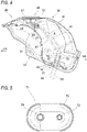
- Fig. 2 is a perspective view of the fuel tank according to the present embodiment as viewed from above.
- Fig. 3 is a perspective view of the fuel tank according to the present embodiment as viewed from below.
- Fig. 4 is a cross-sectional view of the fuel tank taken along a line A-A in Fig. 3 .
- Fig. 5 is a front view of the inner connection plate according to the present embodiment.
- a tank body 31 of the fuel tank 30 is formed by joining outer edges of an outer panel 41 forming a tank outer shell and the inner panel 61 forming a tank inner shell (see Fig. 3 ).
- the outer panel 41 and the inner panel 61 form a fuel storage space S (see Fig. 4 ).
- the outer panel 41 is formed in a substantially dome shape such that symmetrical panel members 42L, 42R are joined along a center line in a front-rear direction and rise from a panel rear portion 43 toward a panel front portion 44.
- a surface of the panel front portion 44 of the outer panel 41 is lowered by one step as a whole, and a tank cover 59 (see Fig. 10C ) is formed to be attachable to the panel front portion 44.
- a circular opening 45 is formed in a center of the panel front portion 44 of the outer panel 41, and a tank inlet 46 is joined to the circular opening 45.
- the tank inlet 46 includes a bottomed cylindrical inlet plate 47 and an inlet pipe 49 attached to a bottom wall of the inlet plate 47.
- a tank cap (not shown) is attached to the inlet plate 47, and a fuel filling port of the inlet pipe 49 is opened and closed by the tank cap.
- An upper breather pipe 51 and an upper drain pipe 52 as outer pipes are joined to the bottom wall of the inlet plate 47.
- the upper breather pipe 51 and the upper drain pipe 52 extend from the bottom wall of the inlet plate 47 into the tank (particularly, see Fig. 4 ).
- An upstream side of a breather pipe is formed by the upper breather pipe 51, and an upstream side of a drain pipe is formed by the upper drain pipe 52.
- the inlet plate 47 is slightly recessed around a joint portion of the upper drain pipe 52, and liquid droplets on the inlet plate 47 are easily collected at an inlet of the upper drain pipe 52.
- Screw holes 54 for three nuts 53 are exposed from the bottom wall of the inlet plate 47.
- the tank cap is attached to the tank inlet 46 by screwing the tank cap into these screw holes 54.
- Seat surfaces 55L, 55R for a cover bracket are formed on both left and right sides of the panel front portion 44 of the outer panel 41.
- the tank cover 59 is attached to the panel front portion 44 of the outer panel 41 via the cover bracket. A periphery of the tank cap is covered with the tank cover 59 so as to hide the tank inlet 46.
- the inner panel 61 includes a panel rear portion 63 formed in a planar shape, and is formed in a substantially dome shape so as to rise from a front side of the panel rear portion 63 toward a panel front portion 64.
- a circular opening 65 is formed in a center of a bottom surface of the panel rear portion 63 of the inner panel 61, and an upper side of a fuel pump (not shown) is inserted into the tank through the circular opening 65.
- a plurality of screw holes 66 are formed around the circular opening 65, and a flange portion on a lower side of the fuel pump is screwed into the screw holes 66.
- the fuel in the tank is pumped out by the fuel pump and sent to a fuel injector (not shown) of the engine 14 (see Fig. 1 ).
- An oval opening 67 is formed next to the circular opening 65 (on a left side in the present embodiment), and an inner connection plate 71 is joined to the opening 67.
- the inner connection plate 71 is formed in a dome shape bulging into the tank, and a lower breather pipe 73 and a lower drain pipe 74 as inner pipes are joined to an upper bottom wall of the inner connection plate 71.
- the lower breather pipe 73 and the lower drain pipe 74 pass through the upper bottom wall of the inner connection plate 71 (particularly, see Fig. 4 ).
- a downstream side of the breather pipe is formed by the lower breather pipe 73, and a downstream side of the drain pipe is formed by the lower drain pipe 74.
- the upper breather pipe 51 and the upper drain pipe 52 are substantially L-shaped, and the lower breather pipe 73 and the lower drain pipe 74 are straight.
- a downstream end of the upper breather pipe 51 and an upstream end of the lower breather pipe 73 are connected to each other via a first breather hose (pipe) 81
- a downstream end of the upper drain pipe 52 and an upstream end of the lower drain pipe 74 are connected to each other via a first drain hose (pipe) 82.
- the inlet plate 47 and the inner connection plate 71 are connected to each other by the first breather hose 81 and the first drain hose 82 passing inside the outer panel 41 and the inner panel 61.
- a second breather hose 83 is connected to a downstream end of the lower breather pipe 73 outside the tank, and a second drain hose 84 is connected to a downstream end of the lower drain pipe 74 outside the tank.
- the upper breather pipe 51, the first breather hose 81, the lower breather pipe 73 and the second breather hose 83 form a breather pipe that guides a gas component in the tank inlet 46 to outside of the fuel tank 30.
- the upper drain pipe 52, the first drain hose 82, the lower drain pipe 74 and the second drain hose 84 form a drain pipe that discharges liquid droplets in the tank inlet 46.
- the oval opening 67 of the inner panel 61 is formed along an outer peripheral edge 75 of the inner connection plate 71, and an opening edge 68 of the inner panel 61 protrudes to the outside of the tank over the entire periphery.
- the outer peripheral edge 75 of the inner connection plate 71 protrudes from the opening 67 to the outside of the tank, and a lower end surface of the outer peripheral edge 75 of the inner connection plate 71 is aligned with a lower end surface of the opening edge 68 of the inner panel 61.
- the outer peripheral edge 75 of the inner connection plate 71 is easily and reliably joined to the opening edge 68 of the inner panel 61 from the outside of the tank.
- the lower breather pipe 73 and the lower drain pipe 74 pass through the upper bottom wall of the inner connection plate 71 substantially perpendicularly.
- the inner connection plate 71 is viewed from a front side, that is, when the inner connection plate 71 is directly faced, the downstream end of the lower breather pipe 73 and the downstream end of the lower drain pipe 74 are located inward than the outer peripheral edge 75 of the inner connection plate 71 (see Fig. 5 ). Therefore, when the inner connection plate 71 and the inner panel 61 are joined by welding, the lower breather pipe 73 and the lower drain pipe 74 protruding to the outside of the tank do not interfere with a welding torch.
- an outer component 32 including the outer panel 41 and outer related components, and an inner component 33 including the inner panel 61 and inner related components are individually manufactured.
- the outer component 32 and the inner component 33 are integrated to manufacture the fuel tank 30.
- the outer component 32 and the inner component 33 are each made of titanium or titanium alloy, and members are welded to each other in an oxygen-free environment, so that a weight of the fuel tank 30 is reduced and weather resistance and rust resistance are improved.
- the inlet plate 47 and the inner connection plate 71 are formed in a size that can be accommodated in a furnace. Since the outer panel 41 and the inlet plate 47 are formed separately in this manner, the inlet plate 47, the upper breather pipe 51 and the upper drain pipe 52 are brazed in the furnace. Similarly, since the inner panel 61 and the inner connection plate 71 are formed separately, the inner connection plate 71, the lower breather pipe 73 and the lower drain pipe 74 are brazed in the furnace.
- FIGS. 6A to 10C are transition views showing a method for manufacturing a fuel tank made of a steel plate according to a comparative example.
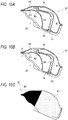
- Figs. 8A to 10C are transition views showing a method for manufacturing the fuel tank made of titanium according to the present embodiment.
- the fuel tank made of the steel plate according to the comparative example is different from the fuel tank according to the present embodiment in that each of a breather pipe and a drain pipe is formed of one pipe, and an inner connection plate is not formed.
- an inner component 99 is performed.
- an attachment component to a fuel pump and an inner-related component such as a bracket for a vehicle body frame are spot-welded to an inner panel 97.
- work of integrating the outer component 91 and the inner component 99 is performed.
- an outer peripheral edge of the outer panel 92 and an outer peripheral edge of the inner panel 97 are aligned with each other, and the breather pipe 95 and the drain pipe 96 are inserted into through holes of the inner panel 97.
- the outer peripheral edge of the outer panel 92 and the outer peripheral edge of the inner panel 97 are seam-welded to integrate the outer component 91 and the inner component 99.
- Fig. 7C work of joining the breather pipe 95 and the drain pipe 96 to the inner panel 97 is performed.
- the breather pipe 95 and the drain pipe 96 are manually brazed to the inner panel 97 in the atmosphere.
- Fig. 7D surface treatment work on the outer panel 92 is performed.
- coating treatment is selected as surface treatment on the outer panel 92.
- a tank cover 98 is attached to the outer panel 92 to manufacture the fuel tank 90.
- the fuel tank made of titanium since properties of titanium are close to those of iron as compared with aluminum, some manufacturing equipment and the like are used in common with the fuel tank made of the steel plate.
- individual components of the fuel tank are manufactured.
- the outer panel 41 and the inner panel 61 are press-formed.
- the manufacturing equipment such as a die or a press machine for the fuel tank 90 made of the steel plate can be used.
- the manufacturing equipment of the fuel tank 90 made of the steel plate can also be used for manufacturing some peripheral components of the outer panel 41 and the inner panel 61.
- work of manufacturing the outer component 32 (a step of manufacturing the outer component) is performed.
- work of forming the outer panel 41 shown in Fig. 8A is performed.
- a shield gas is blown onto mating surfaces of the panel members 42L, 42R, and the mating surfaces of the panel members 42L, 42R are plasma-welded in the oxygen-free environment.
- An inlet related component such as a cover bracket is spot-welded to the outer panel 41.
- the manufacturing equipment of the fuel tank 90 made of the steel plate can be used. In spot welding, since joint surfaces of the members are blocked from the atmosphere, an influence of oxygen on the outer panel 41 made of titanium is minimized.
- work of manufacturing the inner component 33 (a step of manufacturing the inner component 33) is performed.
- work of forming the inner panel 61 shown in Fig. 9A is performed.
- an attachment component to a fuel pump and an inner-related component such as a bracket for a vehicle body frame are spot-welded to the inner panel 61.
- the manufacturing equipment of the fuel tank 90 made of the steel plate can be used.
- a step of integrating is performed.
- work of connecting the first breather hose 81 and the first drain hose 82 to the pipes shown in Fig. 10A is performed.
- the upper breather pipe 51 of the outer component 32 and the lower breather pipe 73 of the inner component 33 are connected to each other via the first breather hose 81.
- the upper drain pipe 52 of the outer component 32 and the lower drain pipe 74 of the inner component 33 are connected to each other via the first drain hose 82.
- a rubber hose or a resin hose having flexibility and oil resistance is used for the first breather hose 81 and the first drain hose 82.
- surface treatment work (a step of roughening) is performed on the outer panel 41.
- shot treatment is selected as surface treatment on the outer panel 41. Since titanium has excellent weather resistance and rust resistance, physical properties do not deteriorate even when coating treatment is not performed, but a surface of the outer panel 41 has processing marks such as press scratches and beads. The shot treatment removes the processing marks, and the exposed metal surface improves the appearance.
- the tank cover 59 is attached to the outer panel 41 to manufacture the fuel tank 30. As the tank cover 59, a cover the same as that of the fuel tank 90 made of the steel plate can be used.
- the outer panel 41 and the inlet plate 47 are formed separately, and the inner panel 61 and the inner connection plate 71 are formed separately. Therefore, even in a case of in-furnace brazing suitable for titanium but having size restrictions, in-furnace brazing can be used for joining pipes to the inlet plate 47 and the inner connection plate 71. In this way, it is possible to flexibly select work that satisfies manufacturing restrictions due to the material and size.
- the fuel tank 30 in which the pipes passes through the tank is manufactured. In order to maintain the appearance, a large tank cover that covers the entire tank is not required, and without a double structure, capacity of the fuel tank 30 is not reduced.
- the fuel tank according to the present embodiment can also be appropriately applied to other straddle-type vehicles such as a buggy-type motor tricycle.
- the straddle-type vehicle is not limited to general vehicles in which a rider rides in a posture of straddling a seat, but also includes a scooter-type vehicle in which a rider rides without straddling a seat.
- the method for manufacturing the fuel tank made of titanium has been described, but this manufacturing method can also be applied to manufacture of fuel tanks made of other materials.
- the present invention is effective for manufacturing a fuel tank using a material that requires joining in an oxygen-free environment or a low-oxygen environment.
- the breather pipe is formed by four components including the upper breather pipe, the first breather hose, the lower breather pipe and the second breather hose, but the breather pipe may be formed by one component.
- the drain pipe is formed by four components including the upper drain pipe, the first drain hose, the lower drain pipe and the second drain hose, but the drain pipe may be formed by one component.
- the outer component and the inner component are made of titanium, but some components of the outer component and the inner component may be made of different materials.
- the upper breather pipe, the lower breather pipe, the upper drain pipe and the lower drain pipe may be made of iron.
- joining methods such as plasma welding, spot welding, in-furnace brazing, TIG welding and seam welding are used, but other joining methods that have less influence of oxygen on a joining target may be adopted.
- a fuel tank (30) includes: an outer component (32) including an outer panel (41) forming a tank outer shell and an inlet plate (47) formed separately from the outer panel; an inner component (33) including an inner panel (61) forming a tank inner shell and an inner connection plate (71) formed separately from the inner panel; and a pipe (the first breather hose 81 and the first drain hose 82) passing through inside of the outer panel and the inner panel and connecting the inlet plate and the inner connection plate.
- the inlet plate is joined to the outer panel, the inner connection plate is joined to the inner panel, and the inner panel is joined to the outer panel. According to this configuration, the outer panel and the inlet plate are formed separately, and the inner panel and the inner connection plate are formed separately.
- the work can be performed on the inlet plate and the inner connection plate. In this way, it is possible to flexibly select work that satisfies manufacturing restrictions due to the material and size.
- the outer component and the inner component are integrated, so that the fuel tank in which the pipe passes through the tank is manufactured. In order to maintain an appearance, a large tank cover that covers the entire tank is not required, and without a double structure, capacity of the fuel tank is not reduced.
- the outer component and the inner component are made of titanium or titanium alloy. According to this configuration, members can be joined to each other in an environment suitable for titanium or titanium alloy, whereby a weight of the fuel tank can be reduced and weather resistance and rust resistance can be improved.
- an opening (67) along an outer peripheral edge (75) of the inner connection plate is formed in the inner panel and the outer peripheral edge of the inner connection plate protrudes from the opening to outside of the tank, and an opening edge (68) of the inner panel protrudes to the outside of the tank and the outer peripheral edge of the inner connection plate is joined to the opening edge of the inner panel.
- the outer peripheral edge of the inner connection plate can be easily and reliably welded to the opening edge of the inner panel from the outside of the tank.
- the outer component includes an outer pipe (the upper breather pipe 51 and the upper drain pipe 52) extending from the inlet plate into the tank and the inner component includes an inner pipe (the lower breather pipe 73 and the lower drain pipe 74) penetrating the inner connection plate, and the pipe is connected to the outer pipe and the inner pipe, the outer pipe is joined to the inlet plate and the inner pipe is joined to the inner connection plate.
- the inlet plate and the outer pipe are formed separately, and the inner connection plate and the inner pipe are formed separately. Therefore, a joining method suitable for the material and size of the inlet plate and the outer pipe and a joining method suitable for the material and size of the inner connection plate and the inner pipe can be used.
- an end portion protruding from the inner pipe to the outside of the tank is located inward than the outer peripheral edge of the inner connection plate in a state of directly facing the inner connection plate. According to this configuration, when the inner connection plate is joined to the inner panel, the end portion protruding from the inner pipe to the outside of the tank does not interfere.
- a method for manufacturing the fuel tank according to the present embodiment includes: a step of manufacturing an outer component by joining an inlet plate formed separately from an outer panel forming a tank outer shell to the outer panel; a step of manufacturing an inner component by joining an inner connection plate formed separately from an inner panel forming a tank inner shell to the inner panel; and a step of connecting the inlet plate and the inner connection plate by a pipe passing through the tank, and joining and integrating the outer panel and the inner panel.
- the outer panel and the inlet plate are formed separately, and the inner panel and the inner connection plate are formed separately. Therefore, even when work is suitable for a material of each member but has size restrictions, the work can be performed on the inlet plate and the inner connection plate.
- the outer component and the inner component are integrated, so that the fuel tank in which the pipe passes through the tank is manufactured. In order to maintain an appearance, a large tank cover that covers the entire tank is not required, and without a double structure, capacity of the fuel tank is not reduced.
- the step of manufacturing the outer component includes a sub-step of brazing an outer pipe to the inlet plate in a furnace and a sub-step of TIG-welding the inlet plate to the outer panel
- the step of manufacturing the inner component includes a sub-step of brazing an inner pipe to the inner connection plate in the furnace and a sub-step of TIG-welding the inner connection plate to the inner panel
- the step of integrating includes a sub-step of connecting the outer pipe and the inner pipe by the pipe and a sub-step of seam-welding the outer panel and the inner panel.
- the outer component and the inner component are made of titanium or titanium alloy, and the method further includes: a step of roughening a surface of the outer panel joined to the inner panel by performing shot treatment on the surface of the outer panel.
- a processing mark such as a scratch or a welding mark on the surface of the outer panel can be eliminated. It is not necessary to cover the surface of the outer panel with a coating film or the like, and a metal surface made of titanium or titanium alloy can be exposed to the outside to improve the appearance.
- a weight of the fuel tank can be reduced, and weather resistance and rust resistance can be improved.
Landscapes
- Engineering & Computer Science (AREA)
- Mechanical Engineering (AREA)
- Life Sciences & Earth Sciences (AREA)
- Sustainable Development (AREA)
- Sustainable Energy (AREA)
- Chemical & Material Sciences (AREA)
- Combustion & Propulsion (AREA)
- Transportation (AREA)
- Cooling, Air Intake And Gas Exhaust, And Fuel Tank Arrangements In Propulsion Units (AREA)
Abstract
A fuel tank includes an outer component including an outer panel forming a tank outer shell and an inlet plate formed separately from the outer panel, an inner component including an inner panel forming a tank inner shell and an inner connection plate formed separately from the inner panel, and a pipe passing through inside of the outer panel and the inner panel and connecting the inlet plate and the inner connection plate. The inlet plate is joined to the outer panel, the inner connection plate is joined to the inner panel, and the inner panel is joined to the outer panel.
Description
- The present invention relates to a fuel tank and a method for manufacturing the fuel tank.
- A fuel tank of a straddle-type vehicle is provided with pipes such as a breather pipe and a drain pipe. A fuel tank of this type is known in which a pipe passes through the tank (for example, see Patent Literature 1). In the fuel tank disclosed in
Patent Literature 1, a tank inlet is provided in an outer panel, and the pipe extends from the tank inlet to outside of the tank through a bottom wall of an inner panel. Since the pipe is hidden in the tank, an appearance of the fuel tank is maintained without covering the outside of the fuel tank with a tank cover, unlike a structure in which a pipe passes through outside of a tank. - Patent Literature 1:
JP-A-2005-008023 - In recent years, fuel tanks are manufactured using various materials. At the time of manufacturing the fuel tank disclosed in
Patent Literature 1, brazing or the like is used for joining panels and pipes, but it may be difficult to manufacture the fuel tank due to manufacturing restrictions depending on the material and size. - The present invention has been made in view of the above, and an object thereof is to provide a fuel tank capable of maintaining an appearance of the fuel tank by allowing a pipe to pass through the tank even when there are manufacturing restrictions due to the material and size, and a method for manufacturing the fuel tank.
- A fuel tank according to an aspect of the present invention includes: an outer component including an outer panel forming a tank outer shell and an inlet plate formed separately from the outer panel; an inner component including an inner panel forming a tank inner shell and an inner connection plate formed separately from the inner panel; and a pipe passing through inside of the outer panel and the inner panel and connecting the inlet plate and the inner connection plate. The inlet plate is joined to the outer panel, the inner connection plate is joined to the inner panel, and the inner panel is joined to the outer panel.
- According to the fuel tank according to one aspect of the present invention, the outer panel and the inlet plate are formed separately, and the inner panel and the inner connection plate are formed separately. Therefore, even when work is suitable for a material of each member but has size restrictions, the work can be performed on the inlet plate and the inner connection plate. In this way, it is possible to flexibly select work that satisfies manufacturing restrictions due to the material and size. In addition, the outer component and the inner component are integrated, so that the fuel tank in which the pipe passes through the tank is manufactured. In order to maintain an appearance, a large tank cover that covers the entire tank is not required, and without a double structure, capacity of the fuel tank is not reduced.
-
-
Fig. 1 is a left side view of a straddle-type vehicle according to an embodiment of the present invention. -
Fig. 2 is a perspective view of a fuel tank according to the present embodiment as viewed from above. -
Fig. 3 is a perspective view of the fuel tank according to the present embodiment as viewed from below. -
Fig. 4 is a cross-sectional view of the fuel tank taken along a line A-AinFig. 3 . -
Fig. 5 is a front view of an inner connection plate according to the present embodiment. -
Figs. 6A to 6C are transition views showing a method for manufacturing a fuel tank made of a steel plate according to a comparative example. -
Figs. 7A to7D are transition views showing the method for manufacturing the fuel tank made of the steel plate according to the comparative example. -
Figs. 8A to 8C are transition views showing a method for manufacturing the fuel tank made of titanium according to the present embodiment. -
Figs. 9A to 9C are transition views showing the method for manufacturing the fuel tank made of titanium according to the present embodiment. -
Figs. 10A to 10C are transition views showing the method for manufacturing the fuel tank made of titanium according to the present embodiment. - A fuel tank according to an aspect of the present invention includes an outer component in which an inlet plate is joined to an outer panel forming a tank outer shell, and an inner component in which an inner connection plate is joined to an inner panel forming a tank inner shell. The outer panel and the inlet plate are formed separately, and the inner panel and the inner connection plate are formed separately. Therefore, even when work is suitable for a material but has size restrictions, the work can be performed on the inlet plate and the inner connection plate. In this way, it is possible to flexibly select work that satisfies manufacturing restrictions due to the material and size. In addition, the outer component and the inner component are integrated, so that the fuel tank in which the pipe passes through the tank is manufactured. In order to maintain an appearance, a large tank cover that covers the entire tank is not required, and without a double structure, capacity of the fuel tank is not reduced.
- Hereinafter, an embodiment will be described in detail with reference to the accompanying drawings.
Fig. 1 is a left side view of a straddle-type vehicle according to the present embodiment. In the following drawings, an arrow FR indicates a vehicle front side, an arrow RE indicates a vehicle rear side, an arrow L indicates a vehicle left side, and an arrow R indicates a vehicle right side. - As shown in
Fig. 1 , a straddle-type vehicle 1 is configured by mounting various components such as anengine 14 and an electrical system on a twin-spar typevehicle body frame 10 formed by aluminum casting. Thevehicle body frame 10 includes a pair ofmain frames 11 branching from a head pipe (not shown) to left and right sides and extending rearward, and a pair of down frames (not shown) branching from the head pipe to the left and right sides and extending downward. A rear portion of theengine 14 is supported by the pair ofmain frames 11, and a front portion of theengine 14 is supported by the pair of down frames. Since theengine 14 is supported by thevehicle body frame 10, a rigidity of the entire vehicle is ensured. - A front side portion of the
main frame 11 is atank rail 12 located above theengine 14, and afuel tank 30 is supported by thetank rail 12. A rear side portion of themain frame 11 is abody frame 13 located behind theengine 14, and aswing arm 15 is swingably supported at a substantially intermediate position of thebody frame 13 in an upper-lower direction. A seat rail (not shown) and a backstay (not shown) extend rearward from an upper portion of thebody frame 13. Arider seat 21 and apillion seat 22 are supported on the seat rail behind thefuel tank 30. - A pair of
front forks 23 are steerably supported by the head pipe via a steering shaft (not shown). Afront wheel 24 is rotatably supported by lower portions of thefront forks 23, and an upper portion of thefront wheel 24 is covered with afront fender 25. Theswing arm 15 extends rearward from thebody frame 13. Arear wheel 26 is rotatably supported at a rear end of theswing arm 15, and therear wheel 26 is covered with arear fender 27 from above. Theengine 14 is coupled to therear wheel 26 via a chain drive type transmission mechanism, and power from theengine 14 is transmitted to therear wheel 26 via the transmission mechanism. - Such a straddle-type vehicle is often equipped with a fuel tank made of a steel plate for reasons such as productivity and cost, but may be equipped with a fuel tank made of a nonferrous metal or a resin, which is advantageous in terms of specific gravity. Most of nonferrous metal fuel tanks are made of aluminum, and many of resin fuel tanks are made of polyethylene (PE) or nylon (PA). All of them have manufacturing methods different from those of steel plate fuel tanks, and require special manufacturing equipment and molds. Recently, manufacture of a fuel tank made of titanium, which has properties close to those of iron as compared with aluminum, as a nonferrous metal, has been studied.
- One of the properties of titanium is a property of easily deteriorating due to reacting with oxygen, and thus manual brazing (torch brazing) in atmosphere, which has been performed at the time of manufacturing a fuel tank made of a steel sheet, cannot be performed. Brazing is employed in a fuel tank that requires airtightness, as a welding method for a portion where a working range is narrow, such as joining of pipes, in order to fill a gap between members by a capillary action without melting a base material. When in-furnace brazing is performed, the brazing can be performed in an oxygen-free environment, but a large component such as a panel component of a fuel tank cannot be put into a furnace, and pipes cannot be directly welded to the panel component.
- In a case of a fuel tank made of a steel plate, since brazing work can be performed in the atmosphere, pipes can be manually brazed to a tank inlet of an outer panel, and the pipes can be manually brazed directly to an inner panel while passing through the tank. In a case of a fuel tank made of titanium, it is necessary to perform all welding in an oxygen-free environment, but since pipes cannot be brazed to a large inner panel in a furnace as described above, it is difficult for the pipes to pass through the tank. For this reason, in a general fuel tank made of titanium, a rubber hose is extended from a tank inlet to outside of the tank.
- In order to maintain an appearance of the fuel tank, it is necessary to cover the fuel tank with a tank cover so as to hide the rubber hose outside the tank. When the tank cover is attached to the fuel tank, an advantage of reducing a weight due to titanium is reduced, and the fuel tank has a double structure, resulting in reduction of capacity. Therefore, in the
fuel tank 30 according to the present embodiment, connection plates for pipes are separated from aninner panel 61 in a size that allows in-furnace brazing (seeFig. 4 ). Thereby, even in a case of thefuel tank 30 made of titanium, which is subject to manufacturing restrictions due to the material and size, it is possible to maintain an appearance of thefuel tank 30 by allowing the pipes to pass through the tank. - Hereinafter, the fuel tank will be described with reference to
Figs. 2 to 5 .Fig. 2 is a perspective view of the fuel tank according to the present embodiment as viewed from above.Fig. 3 is a perspective view of the fuel tank according to the present embodiment as viewed from below.Fig. 4 is a cross-sectional view of the fuel tank taken along a line A-A inFig. 3 .Fig. 5 is a front view of the inner connection plate according to the present embodiment. - As shown in
Fig. 2 , atank body 31 of thefuel tank 30 is formed by joining outer edges of anouter panel 41 forming a tank outer shell and theinner panel 61 forming a tank inner shell (seeFig. 3 ). Theouter panel 41 and theinner panel 61 form a fuel storage space S (seeFig. 4 ). Theouter panel 41 is formed in a substantially dome shape such thatsymmetrical panel members rear portion 43 toward apanel front portion 44. A surface of thepanel front portion 44 of theouter panel 41 is lowered by one step as a whole, and a tank cover 59 (seeFig. 10C ) is formed to be attachable to thepanel front portion 44. - A
circular opening 45 is formed in a center of thepanel front portion 44 of theouter panel 41, and atank inlet 46 is joined to thecircular opening 45. Thetank inlet 46 includes a bottomedcylindrical inlet plate 47 and aninlet pipe 49 attached to a bottom wall of theinlet plate 47. A tank cap (not shown) is attached to theinlet plate 47, and a fuel filling port of theinlet pipe 49 is opened and closed by the tank cap. When a fuel filling nozzle (not shown) is inserted into theinlet pipe 49 with the tank cap open, fuel is supplied from the fueling nozzle to the storage space S of thetank body 31. - An
upper breather pipe 51 and anupper drain pipe 52 as outer pipes are joined to the bottom wall of theinlet plate 47. Theupper breather pipe 51 and theupper drain pipe 52 extend from the bottom wall of theinlet plate 47 into the tank (particularly, seeFig. 4 ). An upstream side of a breather pipe is formed by theupper breather pipe 51, and an upstream side of a drain pipe is formed by theupper drain pipe 52. Theinlet plate 47 is slightly recessed around a joint portion of theupper drain pipe 52, and liquid droplets on theinlet plate 47 are easily collected at an inlet of theupper drain pipe 52. - Screw holes 54 for three nuts 53 (see
Fig. 4 ) are exposed from the bottom wall of theinlet plate 47. The tank cap is attached to thetank inlet 46 by screwing the tank cap into these screw holes 54. Seat surfaces 55L, 55R for a cover bracket (not shown) are formed on both left and right sides of thepanel front portion 44 of theouter panel 41. When the cover bracket is joined to the seat surfaces 55L, 55R, the tank cover 59 (seeFig. 10C ) is attached to thepanel front portion 44 of theouter panel 41 via the cover bracket. A periphery of the tank cap is covered with thetank cover 59 so as to hide thetank inlet 46. - As shown in
Fig. 3 , theinner panel 61 includes a panelrear portion 63 formed in a planar shape, and is formed in a substantially dome shape so as to rise from a front side of the panelrear portion 63 toward apanel front portion 64. Acircular opening 65 is formed in a center of a bottom surface of the panelrear portion 63 of theinner panel 61, and an upper side of a fuel pump (not shown) is inserted into the tank through thecircular opening 65. A plurality of screw holes 66 are formed around thecircular opening 65, and a flange portion on a lower side of the fuel pump is screwed into the screw holes 66. The fuel in the tank is pumped out by the fuel pump and sent to a fuel injector (not shown) of the engine 14 (seeFig. 1 ). - An
oval opening 67 is formed next to the circular opening 65 (on a left side in the present embodiment), and aninner connection plate 71 is joined to theopening 67. Theinner connection plate 71 is formed in a dome shape bulging into the tank, and alower breather pipe 73 and alower drain pipe 74 as inner pipes are joined to an upper bottom wall of theinner connection plate 71. Thelower breather pipe 73 and thelower drain pipe 74 pass through the upper bottom wall of the inner connection plate 71 (particularly, seeFig. 4 ). A downstream side of the breather pipe is formed by thelower breather pipe 73, and a downstream side of the drain pipe is formed by thelower drain pipe 74. - As shown in
Fig. 4 , theupper breather pipe 51 and theupper drain pipe 52 are substantially L-shaped, and thelower breather pipe 73 and thelower drain pipe 74 are straight. A downstream end of theupper breather pipe 51 and an upstream end of thelower breather pipe 73 are connected to each other via a first breather hose (pipe) 81, and a downstream end of theupper drain pipe 52 and an upstream end of thelower drain pipe 74 are connected to each other via a first drain hose (pipe) 82. Theinlet plate 47 and theinner connection plate 71 are connected to each other by thefirst breather hose 81 and thefirst drain hose 82 passing inside theouter panel 41 and theinner panel 61. - A
second breather hose 83 is connected to a downstream end of thelower breather pipe 73 outside the tank, and asecond drain hose 84 is connected to a downstream end of thelower drain pipe 74 outside the tank. In this way, theupper breather pipe 51, thefirst breather hose 81, thelower breather pipe 73 and thesecond breather hose 83 form a breather pipe that guides a gas component in thetank inlet 46 to outside of thefuel tank 30. Theupper drain pipe 52, thefirst drain hose 82, thelower drain pipe 74 and thesecond drain hose 84 form a drain pipe that discharges liquid droplets in thetank inlet 46. - The
oval opening 67 of theinner panel 61 is formed along an outerperipheral edge 75 of theinner connection plate 71, and an openingedge 68 of theinner panel 61 protrudes to the outside of the tank over the entire periphery. The outerperipheral edge 75 of theinner connection plate 71 protrudes from theopening 67 to the outside of the tank, and a lower end surface of the outerperipheral edge 75 of theinner connection plate 71 is aligned with a lower end surface of the openingedge 68 of theinner panel 61. Since the openingedge 68 of theinner panel 61 and the outerperipheral edge 75 of theinner connection plate 71 protrude to the outside of the tank, the outerperipheral edge 75 of theinner connection plate 71 is easily and reliably joined to the openingedge 68 of theinner panel 61 from the outside of the tank. - At this time, the
lower breather pipe 73 and thelower drain pipe 74 pass through the upper bottom wall of theinner connection plate 71 substantially perpendicularly. When theinner connection plate 71 is viewed from a front side, that is, when theinner connection plate 71 is directly faced, the downstream end of thelower breather pipe 73 and the downstream end of thelower drain pipe 74 are located inward than the outerperipheral edge 75 of the inner connection plate 71 (seeFig. 5 ). Therefore, when theinner connection plate 71 and theinner panel 61 are joined by welding, thelower breather pipe 73 and thelower drain pipe 74 protruding to the outside of the tank do not interfere with a welding torch. - When the
fuel tank 30 is manufactured, anouter component 32 including theouter panel 41 and outer related components, and aninner component 33 including theinner panel 61 and inner related components are individually manufactured. After thefirst breather hose 81 and thefirst drain hose 82 are connected, theouter component 32 and theinner component 33 are integrated to manufacture thefuel tank 30. Theouter component 32 and theinner component 33 are each made of titanium or titanium alloy, and members are welded to each other in an oxygen-free environment, so that a weight of thefuel tank 30 is reduced and weather resistance and rust resistance are improved. - As described above, since it is necessary to perform in-furnace brazing in the oxygen-free environment for joining the pipes and the plates, the
inlet plate 47 and theinner connection plate 71 are formed in a size that can be accommodated in a furnace. Since theouter panel 41 and theinlet plate 47 are formed separately in this manner, theinlet plate 47, theupper breather pipe 51 and theupper drain pipe 52 are brazed in the furnace. Similarly, since theinner panel 61 and theinner connection plate 71 are formed separately, theinner connection plate 71, thelower breather pipe 73 and thelower drain pipe 74 are brazed in the furnace. - A method for manufacturing the fuel tank will be described with reference to
Figs. 6A to 10C .Figs. 6A to 7D are transition views showing a method for manufacturing a fuel tank made of a steel plate according to a comparative example.Figs. 8A to 10C are transition views showing a method for manufacturing the fuel tank made of titanium according to the present embodiment. The fuel tank made of the steel plate according to the comparative example is different from the fuel tank according to the present embodiment in that each of a breather pipe and a drain pipe is formed of one pipe, and an inner connection plate is not formed. - In the method for manufacturing the fuel tank made of the steel plate shown in the comparative example, individual components of the fuel tank are manufactured. For example, various panels are press-formed by manufacturing equipment such as a press machine. Next, as shown in
Figs. 6A to6C , work of manufacturing anouter component 91 is performed. First, the work of manufacturing theouter panel 92 shown inFig. 6A is performed. In this case, a shield gas is blown onto mating surfaces ofpanel members panel members outer panel 92. - Next, work of joining a
breather pipe 95 and adrain pipe 96 to aninlet plate 94 shown inFig. 6B is performed. In this case, in a state where thebreather pipe 95 and thedrain pipe 96 are inserted into theinlet plate 94, thebreather pipe 95 and thedrain pipe 96 are manually brazed to theinlet plate 94 in atmosphere. Next, work of joining theinlet plate 94 to theouter panel 92 shown inFig. 6C is performed. In this case, an outer peripheral edge of theinlet plate 94 is welded to an opening edge of theouter panel 92 by metal active gas (MAG) welding while blowing the shield gas. - As shown in
Fig. 7A , work of manufacturing aninner component 99 is performed. In this case, an attachment component to a fuel pump and an inner-related component such as a bracket for a vehicle body frame are spot-welded to aninner panel 97. As shown inFig. 7B , work of integrating theouter component 91 and theinner component 99 is performed. In this case, an outer peripheral edge of theouter panel 92 and an outer peripheral edge of theinner panel 97 are aligned with each other, and thebreather pipe 95 and thedrain pipe 96 are inserted into through holes of theinner panel 97. Then, the outer peripheral edge of theouter panel 92 and the outer peripheral edge of theinner panel 97 are seam-welded to integrate theouter component 91 and theinner component 99. - As shown in
Fig. 7C , work of joining thebreather pipe 95 and thedrain pipe 96 to theinner panel 97 is performed. In this case, thebreather pipe 95 and thedrain pipe 96 are manually brazed to theinner panel 97 in the atmosphere. As shown inFig. 7D , surface treatment work on theouter panel 92 is performed. In afuel tank 90 made of the steel plate, coating treatment is selected as surface treatment on theouter panel 92. By coating a surface of theouter panel 92, an appearance, weather resistance and rust resistance of theouter panel 92 are improved. Then, atank cover 98 is attached to theouter panel 92 to manufacture thefuel tank 90. - In the fuel tank made of titanium shown in the present embodiment, since properties of titanium are close to those of iron as compared with aluminum, some manufacturing equipment and the like are used in common with the fuel tank made of the steel plate. First, individual components of the fuel tank are manufactured. For example, the
outer panel 41 and theinner panel 61 are press-formed. At this time, in press forming of theouter panel 41 and theinner panel 61, which are the most expensive, the manufacturing equipment such as a die or a press machine for thefuel tank 90 made of the steel plate can be used. The manufacturing equipment of thefuel tank 90 made of the steel plate can also be used for manufacturing some peripheral components of theouter panel 41 and theinner panel 61. - As shown in
Figs. 8A to 8C , work of manufacturing the outer component 32 (a step of manufacturing the outer component) is performed. First, work of forming theouter panel 41 shown inFig. 8A is performed. In this case, a shield gas is blown onto mating surfaces of thepanel members panel members outer panel 41. In the welding, the manufacturing equipment of thefuel tank 90 made of the steel plate can be used. In spot welding, since joint surfaces of the members are blocked from the atmosphere, an influence of oxygen on theouter panel 41 made of titanium is minimized. - Next, work of joining the
upper breather pipe 51 and theupper drain pipe 52 to theinlet plate 47 shown inFig. 8B (a sub-step of in-furnace brazing) is performed. In this case, theupper breather pipe 51 and theupper drain pipe 52 are accommodated in the furnace in the state where theupper breather pipe 51 and theupper drain pipe 52 are inserted into theinlet plate 47, and theupper breather pipe 51 and theupper drain pipe 52 are brazed to theinlet plate 47 in the furnace in the oxygen-free environment. Since theinlet plate 47 is formed to have a size that can be accommodated in the furnace, in-furnace brazing having size restrictions can be performed. - Next, work of joining the
inlet plate 47 to theouter panel 41 shown inFig. 8C (a sub-step of TIG welding) is performed. In this case, an outer peripheral edge of theinlet plate 47 is welded to an opening edge of theouter panel 41 by tungsten inert gas (TIG) welding while blowing the shield gas. By partially modifying welding equipment of thefuel tank 90 made of the steel sheet, not only the MAG welding but also the TIG welding can be performed. For this reason, the manufacturing equipment of thefuel tank 90 made of the steel plate can also be used for welding theouter panel 41 and theinlet plate 47. - As shown in
Figs. 9A to 9C , work of manufacturing the inner component 33 (a step of manufacturing the inner component 33) is performed. First, work of forming theinner panel 61 shown inFig. 9A is performed. In this case, an attachment component to a fuel pump and an inner-related component such as a bracket for a vehicle body frame are spot-welded to theinner panel 61. In the welding, the manufacturing equipment of thefuel tank 90 made of the steel plate can be used. - Next, work of joining the
lower breather pipe 73 and thelower drain pipe 74 to theinner connection plate 71 shown inFig. 9B (a sub-step of in-furnace brazing) is performed. In this case, thelower breather pipe 73 and thelower drain pipe 74 are accommodated in the furnace in a state where thelower breather pipe 73 and thelower drain pipe 74 are inserted into theinner connection plate 71, and thelower breather pipe 73 and thelower drain pipe 74 are brazed to theinner connection plate 71 in the furnace in the oxygen-free environment. Since theinner connection plate 71 is formed to have a size that can be accommodated in the furnace, in-furnace brazing having size restrictions can be performed. - Next, work of joining the
inner connection plate 71 to theinner panel 61 shown inFig. 9C (a sub-step of TIG welding) is performed. In this case, the outer peripheral edge of theinner connection plate 71 is welded to the opening edge of theinner panel 61 by tungsten inert gas (TIG) welding while blowing the shield gas. As described above, by partially modifying the welding equipment of thefuel tank 90 made of the steel sheet, not only the MAG welding but also the TIG welding can be performed. For this reason, the manufacturing equipment of thefuel tank 90 made of the steel plate can also be used for welding theinner panel 61 and theinner connection plate 71. - As shown in
Figs. 10A and 10B , work of integrating theouter component 32 and the inner component 33 (a step of integrating) is performed. First, work of connecting thefirst breather hose 81 and thefirst drain hose 82 to the pipes shown inFig. 10A (a sub-step of connecting) is performed. In this case, theupper breather pipe 51 of theouter component 32 and thelower breather pipe 73 of theinner component 33 are connected to each other via thefirst breather hose 81. Theupper drain pipe 52 of theouter component 32 and thelower drain pipe 74 of theinner component 33 are connected to each other via thefirst drain hose 82. A rubber hose or a resin hose having flexibility and oil resistance is used for thefirst breather hose 81 and thefirst drain hose 82. - Next, work of joining the
outer panel 41 and theinner panel 61 shown inFig. 10B (a sub-step of seam welding) is performed. In this case, an outer peripheral edge of theouter panel 41 and an outer peripheral edge of theinner panel 61 are aligned with each other, and the outer peripheral edge of theouter panel 41 and the outer peripheral edge of theinner panel 61 are seam-welded. Also for seam welding, the manufacturing equipment of thefuel tank 90 made of the steel plate can be used. In the seam welding, since joint surfaces of theouter panel 41 and theinner panel 61 are blocked from the atmosphere, an influence of oxygen on theouter panel 41 and theinner panel 61 made of titanium is minimized. - As shown in
Fig. 10C , surface treatment work (a step of roughening) is performed on theouter panel 41. In thefuel tank 30 made of titanium, shot treatment is selected as surface treatment on theouter panel 41. Since titanium has excellent weather resistance and rust resistance, physical properties do not deteriorate even when coating treatment is not performed, but a surface of theouter panel 41 has processing marks such as press scratches and beads. The shot treatment removes the processing marks, and the exposed metal surface improves the appearance. Then, thetank cover 59 is attached to theouter panel 41 to manufacture thefuel tank 30. As thetank cover 59, a cover the same as that of thefuel tank 90 made of the steel plate can be used. - As described above, according to the present embodiment, the
outer panel 41 and theinlet plate 47 are formed separately, and theinner panel 61 and theinner connection plate 71 are formed separately. Therefore, even in a case of in-furnace brazing suitable for titanium but having size restrictions, in-furnace brazing can be used for joining pipes to theinlet plate 47 and theinner connection plate 71. In this way, it is possible to flexibly select work that satisfies manufacturing restrictions due to the material and size. By integrating theouter component 32 and theinner component 33, thefuel tank 30 in which the pipes passes through the tank is manufactured. In order to maintain the appearance, a large tank cover that covers the entire tank is not required, and without a double structure, capacity of thefuel tank 30 is not reduced. - The fuel tank according to the present embodiment can also be appropriately applied to other straddle-type vehicles such as a buggy-type motor tricycle. Here, the straddle-type vehicle is not limited to general vehicles in which a rider rides in a posture of straddling a seat, but also includes a scooter-type vehicle in which a rider rides without straddling a seat.
- In the present embodiment, the method for manufacturing the fuel tank made of titanium has been described, but this manufacturing method can also be applied to manufacture of fuel tanks made of other materials. In particular, the present invention is effective for manufacturing a fuel tank using a material that requires joining in an oxygen-free environment or a low-oxygen environment.
- In the present embodiment, the breather pipe is formed by four components including the upper breather pipe, the first breather hose, the lower breather pipe and the second breather hose, but the breather pipe may be formed by one component. Similarly, in the present embodiment, the drain pipe is formed by four components including the upper drain pipe, the first drain hose, the lower drain pipe and the second drain hose, but the drain pipe may be formed by one component.
- In the present embodiment, the outer component and the inner component are made of titanium, but some components of the outer component and the inner component may be made of different materials. For example, the upper breather pipe, the lower breather pipe, the upper drain pipe and the lower drain pipe may be made of iron.
- In the present embodiment, joining methods such as plasma welding, spot welding, in-furnace brazing, TIG welding and seam welding are used, but other joining methods that have less influence of oxygen on a joining target may be adopted.
- As described above, a fuel tank (30) according to the present embodiment includes: an outer component (32) including an outer panel (41) forming a tank outer shell and an inlet plate (47) formed separately from the outer panel; an inner component (33) including an inner panel (61) forming a tank inner shell and an inner connection plate (71) formed separately from the inner panel; and a pipe (the
first breather hose 81 and the first drain hose 82) passing through inside of the outer panel and the inner panel and connecting the inlet plate and the inner connection plate. The inlet plate is joined to the outer panel, the inner connection plate is joined to the inner panel, and the inner panel is joined to the outer panel. According to this configuration, the outer panel and the inlet plate are formed separately, and the inner panel and the inner connection plate are formed separately. Therefore, even when work is suitable for a material of each member but has size restrictions, the work can be performed on the inlet plate and the inner connection plate. In this way, it is possible to flexibly select work that satisfies manufacturing restrictions due to the material and size. In addition, the outer component and the inner component are integrated, so that the fuel tank in which the pipe passes through the tank is manufactured. In order to maintain an appearance, a large tank cover that covers the entire tank is not required, and without a double structure, capacity of the fuel tank is not reduced. - In the fuel tank according to the present embodiment, the outer component and the inner component are made of titanium or titanium alloy. According to this configuration, members can be joined to each other in an environment suitable for titanium or titanium alloy, whereby a weight of the fuel tank can be reduced and weather resistance and rust resistance can be improved.
- In the fuel tank according to the present embodiment, an opening (67) along an outer peripheral edge (75) of the inner connection plate is formed in the inner panel and the outer peripheral edge of the inner connection plate protrudes from the opening to outside of the tank, and an opening edge (68) of the inner panel protrudes to the outside of the tank and the outer peripheral edge of the inner connection plate is joined to the opening edge of the inner panel. According to this configuration, the outer peripheral edge of the inner connection plate can be easily and reliably welded to the opening edge of the inner panel from the outside of the tank.
- In the fuel tank according to the present embodiment, the outer component includes an outer pipe (the
upper breather pipe 51 and the upper drain pipe 52) extending from the inlet plate into the tank and the inner component includes an inner pipe (thelower breather pipe 73 and the lower drain pipe 74) penetrating the inner connection plate, and the pipe is connected to the outer pipe and the inner pipe, the outer pipe is joined to the inlet plate and the inner pipe is joined to the inner connection plate. According to this configuration, the inlet plate and the outer pipe are formed separately, and the inner connection plate and the inner pipe are formed separately. Therefore, a joining method suitable for the material and size of the inlet plate and the outer pipe and a joining method suitable for the material and size of the inner connection plate and the inner pipe can be used. - In the fuel tank according to the present embodiment, an end portion protruding from the inner pipe to the outside of the tank is located inward than the outer peripheral edge of the inner connection plate in a state of directly facing the inner connection plate. According to this configuration, when the inner connection plate is joined to the inner panel, the end portion protruding from the inner pipe to the outside of the tank does not interfere.
- A method for manufacturing the fuel tank according to the present embodiment includes: a step of manufacturing an outer component by joining an inlet plate formed separately from an outer panel forming a tank outer shell to the outer panel; a step of manufacturing an inner component by joining an inner connection plate formed separately from an inner panel forming a tank inner shell to the inner panel; and a step of connecting the inlet plate and the inner connection plate by a pipe passing through the tank, and joining and integrating the outer panel and the inner panel. According to this configuration, the outer panel and the inlet plate are formed separately, and the inner panel and the inner connection plate are formed separately. Therefore, even when work is suitable for a material of each member but has size restrictions, the work can be performed on the inlet plate and the inner connection plate. In this way, it is possible to flexibly select work that satisfies manufacturing restrictions due to the material and size. In addition, the outer component and the inner component are integrated, so that the fuel tank in which the pipe passes through the tank is manufactured. In order to maintain an appearance, a large tank cover that covers the entire tank is not required, and without a double structure, capacity of the fuel tank is not reduced.
- In the method for manufacturing the fuel tank according to the present embodiment, the step of manufacturing the outer component includes a sub-step of brazing an outer pipe to the inlet plate in a furnace and a sub-step of TIG-welding the inlet plate to the outer panel, the step of manufacturing the inner component includes a sub-step of brazing an inner pipe to the inner connection plate in the furnace and a sub-step of TIG-welding the inner connection plate to the inner panel, and the step of integrating includes a sub-step of connecting the outer pipe and the inner pipe by the pipe and a sub-step of seam-welding the outer panel and the inner panel. According to this configuration, even if each component is formed of the material that is difficult to be welded in atmosphere, the fuel tank can be manufactured satisfactorily.
- In the method for manufacturing the fuel tank according to the present embodiment, the outer component and the inner component are made of titanium or titanium alloy, and the method further includes: a step of roughening a surface of the outer panel joined to the inner panel by performing shot treatment on the surface of the outer panel. According to this configuration, a processing mark such as a scratch or a welding mark on the surface of the outer panel can be eliminated. It is not necessary to cover the surface of the outer panel with a coating film or the like, and a metal surface made of titanium or titanium alloy can be exposed to the outside to improve the appearance. In addition, a weight of the fuel tank can be reduced, and weather resistance and rust resistance can be improved.
- Although the present embodiment has been described, the above-described embodiment and modifications may be combined entirely or partially as another embodiment.
- The technique of the present invention is not limited to the above-described embodiment, and various changes, substitutions and modifications may be made without departing from the spirit of the technical idea of the present invention. Further, the present invention may be implemented using other methods as long as the technical idea can be implemented by the methods through advance of the technique or other derivative technique. Accordingly, the claims cover all embodiments that may be included within the scope of the technical idea.
-
- 30:
- fuel tank
- 32:
- outer component
- 33:
- inner component
- 41:
- outer panel
- 47:
- inlet plate
- 51:
- upper breather pipe (outer pipe)
- 52:
- upper drain pipe (outer pipe)
- 61:
- inner panel
- 67:
- opening
- 68:
- opening edge
- 71:
- inner connection plate
- 73:
- lower breather pipe (inner pipe)
- 74:
- lower drain pipe (inner pipe)
- 75:
- outer peripheral edge
- 81:
- first breather hose (pipe)
- 82:
- first drain hose (pipe)
Claims (8)
- A fuel tank (30) comprising:an outer component (32) including an outer panel (41) forming a tank outer shell and an inlet plate (47) formed separately from the outer panel (41);an inner component (33) including an inner panel (61) forming a tank inner shell and an inner connection plate (71) formed separately from the inner panel (61); anda pipe (81, 82) passing through inside of the outer panel (41) and the inner panel (61) and connecting the inlet plate (47) and the inner connection plate (71), whereinthe inlet plate (47) is joined to the outer panel (41), the inner connection plate (71) is joined to the inner panel (61), and the inner panel (61) is joined to the outer panel (41).
- The fuel tank (30) according to claim 1, wherein
the outer component (32) and the inner component (33) are made of titanium or titanium alloy. - The fuel tank (30) according to claim 1 or 2, whereinan opening (67) along an outer peripheral edge (75) of the inner connection plate (71) is formed in the inner panel (61) and the outer peripheral edge (75) of the inner connection plate (71) protrudes from the opening (67) to outside of the fuel tank (30), andan opening edge (68) of the inner panel (61) protrudes to the outside of the fuel tank (30) and the outer peripheral edge (75) of the inner connection plate (71) is joined to the opening edge (68) of the inner panel (61).
- The fuel tank (30) according to any one of claims 1 to 3, whereinthe outer component (32) includes an outer pipe (51, 52) extending from the inlet plate (47) into the fuel tank (30) and the inner component (33) includes an inner pipe (73, 74) penetrating the inner connection plate (71), andthe pipe (81, 82) is connected to the outer pipe (51, 52) and the inner pipe (73, 74), the outer pipe (51, 52) is joined to the inlet plate (47) and the inner pipe (73, 74) is joined to the inner connection plate (71).
- The fuel tank (30) according to claim 4, wherein
an end portion protruding from the inner pipe (73, 74) to the outside of the fuel tank (30) is located inward than the outer peripheral edge (75) of the inner connection plate (71) in a state of directly facing the inner connection plate (71). - A method for manufacturing a fuel tank (30) comprising:a step of manufacturing an outer component (32) by joining an inlet plate (47) formed separately from an outer panel (41) forming a tank outer shell to the outer panel (41);a step of manufacturing an inner component (33) by joining an inner connection plate (71) formed separately from an inner panel (61) forming a tank inner shell to the inner panel (61); anda step of connecting the inlet plate (47) and the inner connection plate (71) by a pipe (81, 82) passing through the fuel tank (30), and joining and integrating the outer panel (41) and the inner panel (61).
- The method for manufacturing the fuel tank (30) according to claim 6, whereinthe step of manufacturing the outer component (32) includes a sub-step of brazing an outer pipe (51, 52) to the inlet plate (47) in a furnace and a sub-step of TIG-welding the inlet plate (47) to the outer panel (41),the step of manufacturing the inner component (33) includes a sub-step of brazing an inner pipe (73, 74) to the inner connection plate (71) in the furnace and a sub-step of TIG-welding the inner connection plate (71) to the inner panel (61), andthe step of integrating includes a sub-step of connecting the outer pipe (51, 52) and the inner pipe (73, 74) by the pipe (81, 82) and a sub-step of seam-welding the outer panel (41) and the inner panel (61).
- The method for manufacturing the fuel tank (30) according to claim 6 or 7, whereinthe outer component (32) and the inner component (33) are made of titanium or titanium alloy, andthe method further comprising: a step of roughening a surface of the outer panel (41) joined to the inner panel (61) by performing shot treatment on the surface of the outer panel (41).
Applications Claiming Priority (1)
| Application Number | Priority Date | Filing Date | Title |
|---|---|---|---|
| JP2021000165A JP7596791B2 (en) | 2021-01-04 | 2021-01-04 | Fuel tank, and method for manufacturing the fuel tank |
Publications (1)
| Publication Number | Publication Date |
|---|---|
| EP4023478A1 true EP4023478A1 (en) | 2022-07-06 |
Family
ID=79024766
Family Applications (1)
| Application Number | Title | Priority Date | Filing Date |
|---|---|---|---|
| EP21217295.1A Pending EP4023478A1 (en) | 2021-01-04 | 2021-12-23 | Fuel tank and method for manufacturing fuel tank |
Country Status (3)
| Country | Link |
|---|---|
| US (1) | US12139227B2 (en) |
| EP (1) | EP4023478A1 (en) |
| JP (1) | JP7596791B2 (en) |
Citations (4)
| Publication number | Priority date | Publication date | Assignee | Title |
|---|---|---|---|---|
| JPH0516856A (en) * | 1991-07-05 | 1993-01-26 | Honda Motor Co Ltd | Gas-liquid separator of fuel tank |
| JP2005008023A (en) | 2003-06-18 | 2005-01-13 | Yamaha Motor Co Ltd | Breather gas atmosphere release promotion device for saddle-ride type fuel tank |
| JP4761669B2 (en) * | 2001-08-24 | 2011-08-31 | 本田技研工業株式会社 | Manufacturing method of gas-liquid separator for fuel tank |
| US20190100270A1 (en) * | 2017-09-29 | 2019-04-04 | Honda Motor Co., Ltd. | Fuel tank and saddle riding vehicle |
Family Cites Families (8)
| Publication number | Priority date | Publication date | Assignee | Title |
|---|---|---|---|---|
| JP3020853U (en) | 1995-07-21 | 1996-02-06 | 圭充康 古屋 | Automotive parts with a decorative press pattern |
| JP3058639B1 (en) | 1999-10-18 | 2000-07-04 | 川崎重工業株式会社 | Fuel tank |
| CN201890313U (en) | 2010-12-14 | 2011-07-06 | 重庆宗申技术开发研究有限公司 | Diversion device for discharging fuel oil and gas of fuel tank of motorcycle |
| DE102016204648A1 (en) * | 2016-03-21 | 2017-09-21 | Kautex Textron Gmbh & Co. Kg | Operating fluid container with stiffening element and method for producing an operating fluid container |
| JP6649203B2 (en) | 2016-08-09 | 2020-02-19 | 本田技研工業株式会社 | Saddle-type vehicle fuel tank |
| JP6707063B2 (en) * | 2017-08-03 | 2020-06-10 | 本田技研工業株式会社 | Refueling cap and saddle type vehicle |
| JP2019098886A (en) | 2017-11-30 | 2019-06-24 | 本田技研工業株式会社 | Resin fuel tank |
| DE112018004480B4 (en) * | 2017-11-30 | 2024-06-06 | Honda Motor Co., Ltd. | Tank made of plastic |
-
2021
- 2021-01-04 JP JP2021000165A patent/JP7596791B2/en active Active
- 2021-12-23 US US17/561,302 patent/US12139227B2/en active Active
- 2021-12-23 EP EP21217295.1A patent/EP4023478A1/en active Pending
Patent Citations (4)
| Publication number | Priority date | Publication date | Assignee | Title |
|---|---|---|---|---|
| JPH0516856A (en) * | 1991-07-05 | 1993-01-26 | Honda Motor Co Ltd | Gas-liquid separator of fuel tank |
| JP4761669B2 (en) * | 2001-08-24 | 2011-08-31 | 本田技研工業株式会社 | Manufacturing method of gas-liquid separator for fuel tank |
| JP2005008023A (en) | 2003-06-18 | 2005-01-13 | Yamaha Motor Co Ltd | Breather gas atmosphere release promotion device for saddle-ride type fuel tank |
| US20190100270A1 (en) * | 2017-09-29 | 2019-04-04 | Honda Motor Co., Ltd. | Fuel tank and saddle riding vehicle |
Also Published As
| Publication number | Publication date |
|---|---|
| US12139227B2 (en) | 2024-11-12 |
| JP7596791B2 (en) | 2024-12-10 |
| US20220212740A1 (en) | 2022-07-07 |
| JP2022105400A (en) | 2022-07-14 |
Similar Documents
| Publication | Publication Date | Title |
|---|---|---|
| EP1553013B1 (en) | Vehicle body frame of motorcycles | |
| EP2835308B1 (en) | Front cowl stay attachment structure for saddle-ride type vehicle | |
| US20040154852A1 (en) | Vehicle body frame for motorcycle | |
| US11124061B2 (en) | Tank cap structure and saddle-type vehicle | |
| US9150268B2 (en) | Fuel tank and pump assembly, and motorcycle including same | |
| WO2012053126A1 (en) | Fuel supply pipe | |
| JP5976488B2 (en) | Passenger car joint structure, manufacturing method thereof, and passenger car having the joint structure | |
| US12139227B2 (en) | Fuel tank and method for manufacturing fuel tank | |
| EP1659054A2 (en) | Motorcycle fuel tank | |
| US20100108655A1 (en) | Method and device for permanently connecting components of heat- meltable, metallic materials | |
| US9248879B2 (en) | Fuel tank mounting structure of saddle-ride-type vehicle | |
| US11465690B2 (en) | Vehicle body structure | |
| KR101851228B1 (en) | Gas pocket for welding pipes | |
| EP3281854B1 (en) | Fuel tank for saddled vehicle | |
| EP3354550B1 (en) | Saddled vehicle | |
| JP2016182867A (en) | Fuel tank of saddle-riding type vehicle | |
| US10351191B2 (en) | Stand support structure of saddle riding vehicle | |
| EP3514046A1 (en) | Body frame for two-wheeled motor vehicle | |
| CN105666069B (en) | A kind of processing method of automobile crash box | |
| US20170057584A1 (en) | Fuel tank of straddle type vehicle | |
| EP3002074B1 (en) | Method of manufacturing an aluminum fuel tank, an aluminum fuel tank and a straddled vehicle | |
| JP2012086637A (en) | Saddle riding type vehicle | |
| JP2018204534A (en) | Saddle riding type vehicle | |
| CN219274866U (en) | Gas shielded welding frock | |
| EP3002192B1 (en) | Straddled vehicle |
Legal Events
| Date | Code | Title | Description |
|---|---|---|---|
| PUAI | Public reference made under article 153(3) epc to a published international application that has entered the european phase |
Free format text: ORIGINAL CODE: 0009012 |
|
| STAA | Information on the status of an ep patent application or granted ep patent |
Free format text: STATUS: REQUEST FOR EXAMINATION WAS MADE |
|
| 17P | Request for examination filed |
Effective date: 20220121 |
|
| AK | Designated contracting states |
Kind code of ref document: A1 Designated state(s): AL AT BE BG CH CY CZ DE DK EE ES FI FR GB GR HR HU IE IS IT LI LT LU LV MC MK MT NL NO PL PT RO RS SE SI SK SM TR |
|
| STAA | Information on the status of an ep patent application or granted ep patent |
Free format text: STATUS: EXAMINATION IS IN PROGRESS |
|
| 17Q | First examination report despatched |
Effective date: 20250217 |