EP4023395A1 - Flexible actuator - Google Patents
Flexible actuator Download PDFInfo
- Publication number
- EP4023395A1 EP4023395A1 EP20806915.3A EP20806915A EP4023395A1 EP 4023395 A1 EP4023395 A1 EP 4023395A1 EP 20806915 A EP20806915 A EP 20806915A EP 4023395 A1 EP4023395 A1 EP 4023395A1
- Authority
- EP
- European Patent Office
- Prior art keywords
- pair
- wire
- joint portions
- joint
- drive
- Prior art date
- Legal status (The legal status is an assumption and is not a legal conclusion. Google has not performed a legal analysis and makes no representation as to the accuracy of the status listed.)
- Granted
Links
Images



Classifications
-
- B—PERFORMING OPERATIONS; TRANSPORTING
- B25—HAND TOOLS; PORTABLE POWER-DRIVEN TOOLS; MANIPULATORS
- B25J—MANIPULATORS; CHAMBERS PROVIDED WITH MANIPULATION DEVICES
- B25J18/00—Arms
- B25J18/06—Arms flexible
-
- B—PERFORMING OPERATIONS; TRANSPORTING
- B25—HAND TOOLS; PORTABLE POWER-DRIVEN TOOLS; MANIPULATORS
- B25J—MANIPULATORS; CHAMBERS PROVIDED WITH MANIPULATION DEVICES
- B25J9/00—Program-controlled manipulators
- B25J9/10—Program-controlled manipulators characterised by positioning means for manipulator elements
- B25J9/104—Program-controlled manipulators characterised by positioning means for manipulator elements with cables, chains or ribbons
-
- B—PERFORMING OPERATIONS; TRANSPORTING
- B25—HAND TOOLS; PORTABLE POWER-DRIVEN TOOLS; MANIPULATORS
- B25J—MANIPULATORS; CHAMBERS PROVIDED WITH MANIPULATION DEVICES
- B25J9/00—Program-controlled manipulators
- B25J9/06—Program-controlled manipulators characterised by multi-articulated arms
- B25J9/065—Snake robots
-
- B—PERFORMING OPERATIONS; TRANSPORTING
- B25—HAND TOOLS; PORTABLE POWER-DRIVEN TOOLS; MANIPULATORS
- B25J—MANIPULATORS; CHAMBERS PROVIDED WITH MANIPULATION DEVICES
- B25J17/00—Joints
- B25J17/02—Wrist joints
- B25J17/0258—Two-dimensional joints
- B25J17/0266—Two-dimensional joints comprising more than two actuating or connecting rods
-
- A—HUMAN NECESSITIES
- A61—MEDICAL OR VETERINARY SCIENCE; HYGIENE
- A61B—DIAGNOSIS; SURGERY; IDENTIFICATION
- A61B34/00—Computer-aided surgery; Manipulators or robots specially adapted for use in surgery
- A61B34/70—Manipulators specially adapted for use in surgery
- A61B34/71—Manipulators operated by drive cable mechanisms
-
- B—PERFORMING OPERATIONS; TRANSPORTING
- B25—HAND TOOLS; PORTABLE POWER-DRIVEN TOOLS; MANIPULATORS
- B25J—MANIPULATORS; CHAMBERS PROVIDED WITH MANIPULATION DEVICES
- B25J9/00—Program-controlled manipulators
- B25J9/0009—Constructional details, e.g. manipulator supports, bases
-
- B—PERFORMING OPERATIONS; TRANSPORTING
- B25—HAND TOOLS; PORTABLE POWER-DRIVEN TOOLS; MANIPULATORS
- B25J—MANIPULATORS; CHAMBERS PROVIDED WITH MANIPULATION DEVICES
- B25J9/00—Program-controlled manipulators
- B25J9/0009—Constructional details, e.g. manipulator supports, bases
- B25J9/0015—Flexure members, i.e. parts of manipulators having a narrowed section allowing articulation by flexion
-
- B—PERFORMING OPERATIONS; TRANSPORTING
- B25—HAND TOOLS; PORTABLE POWER-DRIVEN TOOLS; MANIPULATORS
- B25J—MANIPULATORS; CHAMBERS PROVIDED WITH MANIPULATION DEVICES
- B25J9/00—Program-controlled manipulators
- B25J9/06—Program-controlled manipulators characterised by multi-articulated arms
-
- A—HUMAN NECESSITIES
- A61—MEDICAL OR VETERINARY SCIENCE; HYGIENE
- A61B—DIAGNOSIS; SURGERY; IDENTIFICATION
- A61B34/00—Computer-aided surgery; Manipulators or robots specially adapted for use in surgery
- A61B34/30—Surgical robots
- A61B2034/305—Details of wrist mechanisms at distal ends of robotic arms
- A61B2034/306—Wrists with multiple vertebrae
-
- B—PERFORMING OPERATIONS; TRANSPORTING
- B25—HAND TOOLS; PORTABLE POWER-DRIVEN TOOLS; MANIPULATORS
- B25J—MANIPULATORS; CHAMBERS PROVIDED WITH MANIPULATION DEVICES
- B25J9/00—Program-controlled manipulators
- B25J9/003—Program-controlled manipulators having parallel kinematics
- B25J9/0078—Program-controlled manipulators having parallel kinematics actuated by cables
Definitions
- the following description relates to a flexible drive manipulator.
- a continuum manipulator includes a hyper-redundant manipulator in which multiple joints are continuously connected to form one manipulator with the number of degrees of freedom greater than the number of actuators, and a flexible manipulator in which one deformable body forms a manipulator to have an infinite number of degrees of freedom.
- the continuum manipulator operates with a gradual curvature, unlike an manipulator formed of a single joint, and accordingly can be mainly used for medical equipment such as medical catheters, endoscopes, or surgical instruments that needs to be inserted along a flexible path, and industrial equipment such as water/sewer pipes, toilet aisles, engine interiors, switchboards, or the like that needs to enter a narrow and curved space.
- medical equipment such as medical catheters, endoscopes, or surgical instruments that needs to be inserted along a flexible path
- industrial equipment such as water/sewer pipes, toilet aisles, engine interiors, switchboards, or the like that needs to enter a narrow and curved space.
- a position control method using a wire inserted along a longitudinal axis of a manipulator can be used, and in the case of using a wire driving method, redundant degrees of freedom are generated by the tension of a wire, which may cause a problem in forming a desired configuration.
- redundant degrees of freedom are generated by the tension of a wire, which may cause a problem in forming a desired configuration.
- due to a structure in which a configuration is adjusted through the tension of the wire there may be a problem in that the configuration can be easily deformed by an external force in a direction different from a direction of the wire.
- An aspect provides a flexible drive manipulator.
- a flexible drive manipulator including a proximal portion, a plurality of joint portions drivably connected from an end of the proximal portion with respect to a longitudinal axis, a distal portion connected to an end of the plurality of joint portions, a pair of drive wires passing through the plurality of j oint portions in parallel along the longitudinal axis, the pair of drive wires configured to drive the plurality of joint portions in a rotational direction of rotation with respect to a transverse axis perpendicular to the longitudinal axis, and a fixing wire passing through the plurality of joint portions in a shape of converging along the longitudinal axis, the fixing wire configured to adjust rigidity of the plurality of joint portions.
- the joint portion may include a pair of contact portions in which both edge portions spaced along a transverse axis perpendicular to a central axis of the joint portion parallel with the longitudinal axis are formed to be recessed along the longitudinal axis, and a pair of fixing wire passages through which the fixing wire passes, the pair of fixing wire passages having an inclined shape so as to converge symmetrically to each other with respect to the longitudinal axis, and an interval between the pair of fixing wire passages of each of the joint portions may sequentially decrease as a joint portion among the plurality of joint portions is connected adjacent to the distal portion, and a portion of the fixing wire passing between the plurality of joint portions may be parallel with the longitudinal axis.
- the fixing wire passage may include a front opening exposed toward the proximal portion, and a rear opening exposed toward the distal portion, and among a pair of joint portions connected adjacent to each other, the rear opening of a joint portion relatively adjacent to the proximal portion and the front opening of a joint portion relatively adjacent to the distal portion may be positioned on the same line parallel with the longitudinal axis.
- a contact portion of each of a plurality of joint portions may rotate so as to be in close contact with an oppositely connected joint portion by a tensile force applied to the pair of drive wires, and among a pair of joint portions contacting adjacent to each other, the rear opening of a joint portion relatively adjacent to the proximal portion and the front opening of a joint portion relatively adjacent to the distal portion may be in close contact with each other so that shapes of respective openings are engaged with each other.
- a portion of the fixing wire passing through the fixing wire passages of the plurality of joint portions may have an inclination of converging toward a central axis of each of the plurality of joint portions, and a portion of the fixing wire passing between the plurality of joint portions may be parallel with a central axis of a joint portion that has been previously passed through.
- the flexible drive manipulator may further include a central wire passing through central axes of the plurality of joint portions, the central wire fixed to the distal portion, and the joint portion may further include a pair of drive wire passages formed to be spaced apart from each other along the transverse axis with respect to the central axis, the pair of drive wire passages through which the pair of drive wires pass, and a central wire passage through which the central wire passes along the central axis.
- the pair of drive wire passages, the pair of fixing wire passages, and the central wire passage of the joint portion may be positioned on the same line along a traverse axis perpendicular to the central axis of the joint portion.
- a flexible drive manipulator it is possible to individually adjust driving and rigidity through two types of wire configurations of a drive wire and a fixing wire, and thus there is an advantage of being simple in terms of a structure and maintaining miniaturization.
- the flexible drive manipulator it is possible to adjust a tensile force applied to a fixing wire, thereby implementing variable rigidity.
- the flexible drive manipulator it is possible to prevent a flexion phenomenon that occurs due to redundant degrees of freedom when only a conventional flat wire is used.
- a fixing wire connected between both joint portions may maintain an angle between central axes of respective joint portions in an operation process that joint portions adjacent to each other are in rolling contact with each other, thereby preventing a magnitude and a direction of a tensile force formed for each section of the fixing wire from being dispersed, and a phenomenon of being caught between the joint portions.
- first, second, A, B, (a), (b), and the like may be used herein to describe components of the example embodiments. These terms are only used to distinguish one component from another component, and essential, order, or sequence of corresponding components are not limited by these terms. It will be understood that when one component is referred to as being “connected to”, “coupled to”, or “linked to” another component, one component may be “connected to”, “coupled to”, or “linked to” another component via a further component although one component may be directly connected to or directly linked to another component.
- a component included in any one example embodiment and another component including a function in common with that of the component will be described using the same designation in other example embodiments. Unless otherwise indicated, a description of one example embodiment may be applied to other example embodiments, and a detailed description will be omitted in an overlapping range.
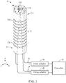
- FIG. 1 is a perspective view of a flexible drive manipulator according to an example embodiment
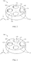
- FIG. 2 is a perspective view of a joint portion according to an example embodiment
- FIG. 3 is a perspective view of a joint portion according to an example embodiment
- FIG. 4 is an exploded perspective view illustrating a coupling relationship between a distal portion and a wire gripping portion according to an example embodiment
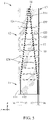
- FIG. 5 is a cross-sectional view of a flexible drive manipulator according to an example embodiment
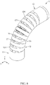
- FIG. 6 is a perspective view illustrating a state in which a flexible drive manipulator is driven in one direction according to an example embodiment
- FIG. 7 is a cross-sectional view illustrating a state in which a flexible drive manipulator is driven in one direction according to an example embodiment.
- a flexible drive manipulator 1 is a continuum manipulator that operates through the tension of a wire.
- the flexible drive manipulator 1 has an elongated shape along a longitudinal axis (z-axis in the drawing) based on a state in which a tensile force is not applied to a drive wire 16, that is, a neutral state that is not driven.
- the flexible drive manipulator 1 may include a proximal portion 11 serving as a reference for driving, a plurality of joint portions 12 drivably connected from an end of the proximal portion 11 with respect to a longitudinal axis, a distal portion 13 connected to an end of the plurality of joint portions 12, a drive wire 16 passing through the plurality of joint portions 12 in parallel along the longitudinal axis to drive the plurality of joint portions 12 in a rotational direction with respect to an axis perpendicular to the longitudinal axis, a fixing wire 17 passing through the plurality of joint portions 12 in a shape of converging along the longitudinal axis to adjust rigidity of the plurality of joint portions 12, a drive actuator 18 connected to the drive wire 16 to adjust a tensile force of the drive wire 16, a fixing actuator 19 connected to the fixing wire 17 to adjust a tensile force of the fixing wire 17, and a controller 15 configured to control the drive actuator 18 and the fixing actuator 19.
- the proximal portion 11 may be a member that serves as a relative reference for a rotational motion in a rotational direction in which the plurality of joint portions 12 are rotated with respect to an axis (y-axis or x-axis in the drawing) perpendicular to the longitudinal axis (z-axis in the drawing).
- a central axis of the proximal portion 11 may have a fixed position so as to correspond to the longitudinal axis.
- the proximal portion 11 may include a drive wire inlet passage 111 through which the drive wire 16 passes along the longitudinal axis and a fixing wire inlet passage 112 through which the fixing wire 17 passes.
- the drive wire inlet passage 111 may be a pair of passages formed through both edge portions spaced apart from the central axis of the proximal portion 11 along the rotational direction as illustrated in FIG. 5 .
- the drive wire inlet passage 111 may be formed at a position spaced apart with respect to the longitudinal axis of the flexible drive manipulator 1.
- the fixing wire inlet passage 112 may be formed as a pair of passages formed through a portion spaced apart side by side from the central axis of the proximal portion 11 along a direction perpendicular to the longitudinal axis as illustrated in FIG. 5 .
- the fixing wire inlet passage 112 may be formed at a position spaced apart at intervals that are symmetrical with respect to the longitudinal axis of the flexible drive manipulator 1.
- a pair of fixing wire inlet passages 112 may be formed inside from the pair of drive wire inlet passages 111, respectively.
- the fixing wire inlet passage 112 may be formed at a position closer than that of the drive wire inlet passage 111.
- the plurality of joint portions 12 may be a set of a plurality of continua continuously connected from the proximal portion 11 through the drive wire 16 and the fixing wire 17.
- the plurality of joint portions 12 may perform flexion or extension motions on the proximal portion 11 in the rotational direction with respect to the axis perpendicular to the longitudinal axis.
- the plurality of joint portions 12 each may have different angles with respect to the joint portions 12 adjacent to each other.
- the plurality of joint portions 12 may be connected in at least one of a rolling contact manner, a gear manner, and a hinge manner.
- a joint portion 12 most adjacent to the proximal portion 11 among the plurality of joint portion 12 may be referred to as a proximal joint portion 12a, and a joint portion 12 most adjacent to the distal portion 13 may be referred to as a distal joint portion 12b.
- each joint portion 12 may include a pair of contact portions 124, a pair of drive wire passages 122, a pair of fixing wire passages 123, and an internal passage 121.
- the contact portions 124 formed on respective joint portions 12 may be in contact with each other, thereby limiting a flexion angle.
- the contact portion 124 may have a recessed shape so as to allow a relative angle change between the joint portions 12 adjacent to each other.
- a protrusion height of the contact portion 124 is formed lower than that of a portion that is in contact with the other adjacent joint portion 12.
- an angle at which respective joint portions 12 are connected to each other may be changed so that the plurality of joint portions 12 are bent toward the rotational direction as illustrated in FIGS. 6 and 7 , and thus the configuration of the flexible drive manipulator 1 may be changed.
- the pair of contact portions 124 may be formed on both surfaces facing the adjacent joint portions 12 along the longitudinal axis as illustrated in FIG. 5 , but it should be noted that the pair of contact portions 124 may be formed only on one surface.
- the pair of drive wire passages 122 may be formed in an edge portion of each of the pair of contact portions 124 along a direction perpendicular to the central axis of the joint portion 12, and the drive wire 16 may pass therethrough.
- the pair of drive wire passages 122 formed in each of the plurality of joint portions 12 are parallel with the longitudinal axis, and have positions that overlap each other along a direction parallel with the longitudinal axis.
- the pair of fixing wire passages 123 may be a pair of passages formed through a portion spaced apart side by side from the central axis of the proximal portion 11 along the direction perpendicular to the central axis of the joint portion 12.
- the pair of fixing wire passages 123 may have a structure of being symmetrical with respect to the central axis of the joint portion 12.
- the pair of fixing wire passages 123 may have an inclined shape so as to converge to the central axis of the joint portion 12 toward a distal direction.
- the pair of fixing wire passages 123 formed in each of the plurality of joint portions 12 may be formed at a position relatively adjacent to the central axis of the joint portion 12 toward the joint portion 12 adjacent to the distal portion 13 from the proximal portion 11.
- an interval between the pair of fixing wire passages 123 of the plurality of joint portions 12 may sequentially decrease along the longitudinal axis, and at the same time, the pair of fixing wires passages 123 of each of the plurality of joint portions 12 may form an oblique inclination in a shape of converging with each other along the longitudinal axis.
- the pair of fixing wire passages 123 are formed at positions close to the pair of drive wire passages 122, respectively.
- the pair of fixing wire passages 123 are respectively formed at positions spaced apart inwardly from the pair of drive wire passages 122.
- the fixing wire 17 passing through the plurality of joint portions 12 as illustrated in FIG. 5 may pass in a shape of converging toward a center as a distance to the longitudinal axis decreases.
- the fixing wire passage 123 and the drive wire passage 122 may be positioned in the same radial direction. According to the above-structure, lateral rigidity may be improved more efficiently.
- the fixing wire passage 123 and the drive wire passage 122 may not be positioned in the same radial direction, and unless otherwise indicated, it should be noted that the scope of the present invention is not necessarily limited to being positioned in the same radial direction.
- the internal passage 121 may be formed to be penetrated along the longitudinal axis.
- various end effectors depending on the purpose including surgical instruments such as a camera, forceps or laser, may be inserted into the internal passage 121 from the proximal portion 11 toward the distal portion 13, and at the same time, a channel through which a cable or wire for manipulating and driving the surgical instruments passes may be formed.
- the internal passage 121 may be formed in plural numbers.
- the plurality of internal passages 121 when viewed from the longitudinal axis, may be formed at a position that does not overlap a virtual straight line connecting the pair of drive wire passages 122 and the pair of fixing wire passages 123 along an axis perpendicular to the central axis.
- the distal portion 13 may form a distal end of the flexible drive manipulator 1, but it should be noted that the proximal portion 11 and the distal portion 13 described herein are merely configurations for giving a relative positional relationship between members connected to the plurality of joint portions 12, and a structure in which each of the proximal portion 11 and the distal portion 13 is connected to an additional external component or a plurality of flexible drive manipulators 1 are connected in series is possible.
- the distal portion 13 may include a pair of drive wire receiving holes 133, a pair of fixing wire receiving holes 134, a central groove 132, a wire gripping portion 14, and an internal passage 131.
- the pair of drive wire receiving holes 133 may be a pair of holes into which the drive wire 16 passing through the plurality of joint portions 12 is inserted along the longitudinal axis.
- the pair of drive wire receiving holes 133 may be formed at positions that overlap the pair of drive wire passages 122 formed in the plurality of joint portion 12.
- ends of the drive wires 16 formed as a pair as illustrated in FIG. 5 may be inserted into and fixed to the pair of drive wire receiving holes 133, respectively.
- the pair of drive wire receiving holes 133 may be formed as one passage in which the pair of drive wire receiving holes 133 communicate with each other, and accordingly one fixing wire 17 may sequentially pass therethrough, and as a result, it is possible to form a structure in which the fixing wire 17 circulates through the flexible drive manipulator 1.
- the drive wire 16 passing through the plurality of joint portions 12 may be inserted into the pair of fixing wire receiving holes 134.
- the pair of fixing wire receiving holes 134 may be formed in a portion spaced apart side by side from the central axis of the distal portion 13 along the direction perpendicular to the longitudinal axis.
- the pair of fixing wire receiving holes 134 may form a passage having a convergent shape while having the same angle as those of the pair of fixing wire passages 123 so as to correspond to the pair of fixing wire passages 123 of the plurality of joint portions 12 having a shape of converging along the longitudinal axis.
- the wire gripping portion 14 may be accommodated in the distal portion 13.
- the central groove 132 may be formed in a center of the distal portion 13 to communicate with the pair of fixing wire receiving holes 134.
- the central groove 132 may be a groove formed to be recessed from an upper side with respect to the longitudinal axis as illustrated in FIG. 4 . Accordingly, the wire gripping portion 14 may be detachably inserted from an upper side of the distal portion 13.
- the central groove 132 may communicate with the pair of fixing wire receiving holes 134 from a lower side with respect to the longitudinal axis.
- the wire gripping portion 14 may grip the fixing wire 17 that is inserted into the central groove 132 to be inserted into the distal portion 13.
- the wire gripping portion 14 may be formed of a material that is relatively more flexible than that of the distal portion 13.
- the wire gripping portion 14 may include a conical shape with a cross-sectional width decreasing toward the longitudinal axis.
- the wire gripping portion 14 may include a fixing passage 141 through which the fixing wire 17 passes.
- the fixing passage 141 may form a passage having a convergent shape while having the same angle as those of the pair of fixing wire passages 123 and the pair of fixing wire receiving holes 134 so as to correspond to the pair of fixing wire passages 123 of the plurality of joint portions 12 having a shape of converging along the longitudinal axis.
- the fixing passage 141 may communicate with the pair of fixing wire receiving holes 134 while facing each other at an accurate position and angle as illustrated in FIG. 5 .
- the fixing wire 17 passing through the fixing passage 141 may be exposed to an upper side of the wire gripping portion 14 as illustrated in FIG. 5 , and the fixing wire 17 may be branched into both sides along a transverse direction perpendicular to the central axis of each joint portion 12 starting from the exposed point to pass through the plurality of joint portions 12.
- the fixing passage 141 may be formed as a pair of passages passing through the wire gripping portion 14, but may be formed as one passage passing through the interior of the fixing passage 141.
- the wire gripping portion 14 may have flexibility and margin to allow a shape of the fixing wire 17 to be changeable within the central groove 132, thereby reducing possibilities of damage caused by sudden driving of the wires 16 and 17 and damage of the wires 16 and 17 themselves.
- the internal passage 131 may be a passage formed through the distal portion 13 along the longitudinal axis.
- the internal passage 121 of the plurality of joint portions 12 and the internal passage 131 of the distal portion 13 may overlap each other. Therefore, a surgical instrument inserted through the internal passage 121 of the plurality of joint portions 12 may be supplied through the internal passage 131 of the distal portion 13 in a distal direction.
- One end of the drive wire 16 may be connected to the drive actuator 18, and the other end of the drive wire 16 may be fixed to the distal portion 13 after sequentially passing through the proximal portion 11 and the plurality of joint portions 12.
- the drive wire 16 may be formed as a pair of wires spaced apart from each other and extending while facing each other along the direction perpendicular to the longitudinal axis.
- a pair of drive wires 16 may be inserted into the pair of drive wire inlet passages 111 of the proximal portion 11, the pair of drive wire passages 122 of the plurality of joint portions 12, and the pair of drive wire receiving holes 133 of the distal portion 13, respectively.
- the pair of drive wires 16 passing through opposite edge portions of the flexible drive manipulator 1 may extend in a state of being parallel with each other toward the longitudinal axis.
- the fixing wire 17 may be connected to the fixing actuator 19, and the other end of the fixing wire 17 may be fixed to the distal portion 13 after sequentially passing through the proximal portion 11 and the plurality of joint portions 12 in a convergent shape.
- the fixing wire 17 may have a structure of a wire passing through the proximal portion 11 and the plurality of joint portions 12 in a state of being spaced apart side by side along the transverse direction perpendicular to the central axis, and two strands of the fixing wire 17 may be connected to each other in the distal portion 13.
- the two strands of the fixing wire 17 may be connected to each other in the fixing passage 141 of the wire gripping portion 14 after passing through the pair of fixing wire inlet passages 112 of the proximal portion 11, the pair of fixing wire passages 123 of the plurality of joint portions 12, and the pair of fixing wire receiving holes 134 of the distal portion 13.
- one fixing wire 17 may pass through the fixing wire passages 123 on the other side which are not passed through by changing a direction while passing through the fixing passage 141 of the wire gripping portion 14, and as a result, may have a structure in which both ends protrude in a proximal direction to be connected to the fixing actuator 19.
- the two strands of the fixing wire 17 may be formed as a pair of wires that each connect between the fixing actuator 19 and the wire gripping portion 14 along an independent path without being connected to each other.
- the two strands of the fixing wire 17 having both ends connected to the fixing actuator 19 may have a structure of converging symmetrically so as to have an oblique angle toward each other while passing through the plurality of joint portions 12.
- the drive actuator 18 may be connected to each of the pair of drive wires 16 to apply a tensile force to each drive wire 16.
- the fixing actuator 19 may be connected to both ends of the fixing wire 17 circulating and passing through the plurality of joint portions 12 and the distal portion 13 to apply a tensile force to the fixing wire 17.
- the controller 15 may drive the plurality of joint portions 12 by adjusting the tensile force applied to the drive wire 16 through the drive actuator 18.
- the controller 15 may apply a relatively large tensile force to one of the pair of drive wires 16 passing through the pair of drive wire passages 122 of each of the plurality of joint portions 12 in a state of being spaced apart side by side along the transverse direction perpendicular to the central axis of each of the plurality of joint portions 12, and thereby the plurality of joint portions 12 may perform a flexion motion toward one direction of rotational directions as illustrated in FIGS. 6 and 7 .
- the controller 15 may adjust rigidity of maintaining a driving configuration of the plurality of joint portions 12 by adjusting the tensile force applied to the fixing wire 17 through the fixing actuator 19.
- a joint structure that is robust to a lateral load and a torque may be provided.
- the flexible drive manipulator 1 may include the fixing wire 17 having a shape of converging toward an end thereof in addition to the drive wire 16 parallel with the longitudinal axis, thereby improving rigidity against the lateral load that cannot be supported by only the pair of drive wires 16 inserted in parallel.
- a tensile force may be applied to the fixing wire 17 even in the neutral state in which the plurality of joint portions 12 are not bent as illustrated in FIG. 5 , thereby improving rigidity so that the plurality of joint portions 12 are maintained in an extended state even though a lateral load and a torque are generated.
- a tensile force may be applied to the fixing wire 17 even in a state in which the plurality of joint portions 12 are bent through the tension of the drive wire 16 as illustrated in FIGS. 6 and 7 , improving rigidity so that the plurality of joint portions 12 maintain a bent configuration even though a lateral load and a torque are generated.
- FIG. 8 is a cross-sectional view of a flexible drive manipulator according to an example embodiment.
- FIG. 8 a configuration of a flexible drive manipulator 1' having a configuration different from those of the example embodiments illustrated in FIGS. 1 to 7 can be confirmed.
- the flexible drive manipulator 1' additionally has a configuration of a central wire 3 passing through a part of the center in the flexible drive manipulator 1 of FIGS. 1 to 7 .
- the flexible drive manipulator 1' may include a proximal portion 11 serving as a reference for driving, a plurality of joint portions 12 drivably connected from an end of the proximal portion 11 with respect to a longitudinal axis, a distal portion 13 connected to an end of the plurality of joint portions 12, a drive wire 16 passing through the plurality of joint portions 12 in parallel along the longitudinal axis to drive the plurality of joint portions 12 in a rotational direction with respect to an axis perpendicular to the longitudinal axis, a fixing wire 17 passing through the plurality of joint portions 12 in a shape of converging along the longitudinal axis to adjust rigidity of the plurality of joint portions 12, a central wire 3 passing through centers of the plurality of joint portions 12 along the longitudinal axis to be fixed to the distal portion 13, a drive actuator 18 connected to the drive wire 16 to adjust a tensile force of the drive wire 16, a fixing actuator 19 connected to the fixing wire 17 to adjust a tensile force of the fixing wire
- the central wire 3 may be fixed to the distal portion 13 after passing through along neutral axes of the plurality of joint portions 12.
- the central wire 3 may be connected to a wire gripping portion 14 to be fixed thereto.
- a tensile force of the central wire 3 may be adjusted and an auxiliary actuator that can be controlled through the controller 15 may be additionally provided.
- each of the plurality of joint portions 12 may further include a central wire passage 125 formed through a central portion along the longitudinal axis so that the central wire 3 passes therethrough.
- the neutral axis of each of the plurality of joint portions 12 may be stably aligned.
- FIG. 9 is a perspective view of a flexible drive manipulator according to an example embodiment
- FIG. 10 is a front view of a flexible drive manipulator according to an example embodiment
- FIG. 11 is a perspective view of a joint portion according to an example embodiment
- FIG. 12 is a bottom perspective view of a wire gripping portion according to an example embodiment.
- FIGS. 9 to 12 a configuration of a flexible drive manipulator 2 having a configuration different from those of the example embodiments illustrated in FIGS. 1 to 7 can be confirmed.
- the flexible drive manipulator 2 has a configuration of a joint portion and a configuration of a wire that are added thereto or are modified so as to allow the flexible drive manipulator 1 using a one degree of freedom driving method illustrated in FIGS. 1 to 7 to be driven with two degrees of freedom.
- the flexible drive manipulator 2 may include a proximal portion 21, a plurality of joint portions 22, a distal portion 23, a first drive wire 261, a second drive wire 262, a first fixing wire 271, a second fixing wire 272, a drive operator 28, a fixing operator 29, and a controller 25.
- the proximal portion 21 may be a member serving as a relative reference for driving in a first rotational direction in which the plurality of joint portions 22 rotate with respect to a first transverse axis (x-axis in the drawing) perpendicular to a longitudinal axis and a second rotational direction in which the plurality of joint portions 22 rotate with respect to a second transverse axis (y-axis in the drawing) perpendicular to the first transverse axis.
- the plurality of joint portions 22 may be a set of a plurality of continua continuously connected from the proximal portion 21 through the first drive wire 261, the second drive wire 262, the first fixing wire 271, and the second fixing wire 272.
- the plurality of joint portions 22 may perform flexion or extension motions on the proximal portion 21 with two degrees of freedom along the first and second rotation directions.
- the plurality of joint portions 22 may include a portion in which two types of joint portions 22 are alternately arranged with each other according to an order of being connected from the proximal portion 21.
- the plurality of joint portions 22 may be divided into a first joint portion 22a and a second joint portion 22b according to a type.
- first joint portion 22a and the second joint portion 22b may be distinguished according to an angle at which the joint portion 22 having the same shape is rotated with respect to a central axis parallel with a longitudinal axis.
- first joint portion 22a when the angle is 0 degrees, it may be referred to as the first joint portion 22a, and when the angle is 90 degrees, it may be referred to as the second joint portion 22b.
- second joint portion 22b when the angle is 90 degrees, it may be referred to as the second joint portion 22b.
- a description of each of the first joint portion 22a and the second joint portion 22b will be replaced with a description of one joint portion 22 below.
- the joint portion 22 may include a pair of first contact portions 224, a pair of second contact portions 225, a pair of first drive wire passages 222a, a pair of second drive wire passages 222b, a pair of first fixing wire passages 223a, a pair of second fixing wire passages 223b, and an internal passage 221.
- the pair of first contact portions 224 may be formed on one surface of both surfaces of the joint portion 22.
- the pair of first contact portions 224 may be formed in directions opposite to each other with respect to a first virtual line (y-axis in the drawing) perpendicular to the central axis of the joint portion 22.
- the pair of first contact portions 224 may have a protrusion height lower than a maximum protrusion height of a portion of the one surface corresponding to the first virtual line.
- the pair of first contact portions 224 may be a portion in which a surface portion of any one of both surfaces facing the joint portions 22 adjacent to each other is recessed in a longitudinal direction toward both edges along a direction (y-axis direction) perpendicular to the central axis.
- the pair of second contact portions 225 may be formed on the other surface of the both surfaces of the joint portion 22.
- the pair of second contact portions 225 may be formed in directions opposite to each other with respect to a second virtual line that is simultaneously perpendicular to the central axis of the joint portion 22 and the first virtual line.
- the pair of second contact portions 225 may have a protrusion height lower than a maximum protrusion height of a portion of the other surface corresponding to the second virtual line.
- the pair of second contact portions 225 may be a portion in which a surface portion of the other of the both surfaces facing the joint portions 22 adjacent to each other is recessed in the longitudinal direction toward the both edges along a direction (x-axis direction) perpendicular to the central axis.
- the first joint portion 22a may have a first contact portion 224 formed on an upper surface thereof and a second contact portion 225 formed on a lower surface thereof.
- the second joint portion 22b may have the second contact portion 225 formed on an upper surface thereof and the first contact portion 224 formed on a lower surface thereof.
- the second joint portion 22b positioned more adjacent to an upper side than the first joint portion 22a may perform a flexion motion in the first rotational direction (rotational direction with respect to the x-axis) perpendicular to the longitudinal axis, and the first joint portion 22a positioned more adjacent to the upper side than the second joint portion 22b may perform a flexion motion in the second rotational direction (rotational direction with respect to the y-axis).
- the plurality of joint portions 22 may be driven with two degrees of freedom in the first and second rotational directions.
- the first drive wire passage 222a may be formed at an edge portion of the first contact portion 224 to allow the first drive wire 261 to pass therethrough.
- the second drive wire passage 222b may be formed at an edge portion of the second contact portion 225 to allow the second drive wire 262 to pass therethrough.
- the pair of first drive wire passages 222a and the pair of second drive wire passages 222b may be formed at positions spaced apart at an angle perpendicular to each other radially along an edge periphery of the joint portion 22 as illustrated in FIG. 11 .
- the first fixing wire passage 223a may be formed in the first contact portion 224 to allow the first fixing wire 271 to pass therethrough.
- the pair of first fixing wire passages 223a may be respectively formed through at points spaced apart inwardly from the pair of first drive wire passages 222a along the first virtual line perpendicular to the central axis.
- the second fixing wire passage 223b may be formed in the second contact portion 225 to allow the second fixing wire 272 to pass therethrough.
- the pair of second fixing wire passages 223b may be respectively formed through at points spaced apart inwardly from the pair of second drive wire passages 222b along the second virtual line perpendicular to the central axis and the first virtual line.
- the pair of first fixing wire passages 223a and the pair of second fixing wire passages 223b each may have a shape of obliquely converging inwardly in an order of a distance from the proximal portion 21 increasing.
- the pair of first fixing wire passages 223a and the pair of second fixing wire passages 223b may be formed at positions spaced apart at an angle perpendicular to each other radially along the periphery of the joint portion 22 as illustrated in FIG. 11 .
- the distal portion 23, which is a member corresponding to a drive end of the plurality of joint portions 22, may be connected to the joint portion 22 that is connected in a last order from the proximal portion 21 among the plurality of joint portions 22.
- the distal portion 23 may include the pair of first drive wire receiving holes 233a, the pair of second drive wire receiving holes 233b, a pair of first fixing wire receiving holes (not illustrated), a pair of second fixing wire receiving holes (not illustrated), a central groove 242, a wire gripping portion 24, and an internal passage 231.
- the pair of first drive wire receiving holes 233a may be a pair of holes into which the first drive wire 261 passing through the plurality of joint portions 22 is inserted along the longitudinal axis.
- the pair of second drive wire receiving holes 233b may be a pair of holes into which the second drive wire 262 passing through the plurality of joint portions 22 is inserted along the longitudinal axis.
- the pair of first drive wire receiving holes 233a and the pair of second drive wire receiving holes 233b may be respectively formed at positions that overlap the pair of first drive wire passages 222a and the pair of second drive wire passages 222b formed in the plurality of joint portions 22.
- the pair of first fixing wire receiving holes may be formed in a portion spaced apart side by side from the center along the first virtual line perpendicular to the central axis.
- the pair of second fixing wire receiving holes may be formed in a portion spaced side by side from the center along the second virtual line perpendicular to the central axis.
- the pair of first fixing wire receiving holes (not illustrated) and the pair of second fixing wire receiving holes (not illustrated) may respectively have the same angle as those of the pair of first fixing wire passages 223a and the pair of second fixing wire passages 223b of the plurality of joint portions 22, and may form a passage having a convergent shape.
- the wire gripping portion 24 may grip the first fixing wire 271 and the second fixing wire 272 that are inserted into the central groove 242 to be inserted into the distal portion 23.
- the wire gripping portion 24 may be formed of a material that is relatively more flexible than that of the distal portion 23.
- the wire gripping portion 24 may include a conical shape with a cross-sectional width decreasing toward the longitudinal axis.
- the wire gripping portion 24 may include a first fixing passage 241a through which the first fixing wire 271 passes, and a second fixing passage 241b through which the second fixing wire 272 passes.
- the first fixing passages 241a may be a pair of passages formed on a point spaced apart side by side from the center along the first virtual line perpendicular to the central axis.
- the second fixing passages 241b may be a pair of passages formed on a point spaced apart side by side from the center along the second virtual line perpendicular to the central axis.
- the first fixing passage 241a and the second fixing passage 241b may respectively have the same angle as those of the pair of first fixing wire passages 223a and the pair of second fixing wire passages 223b of the plurality of joint portions 22, and may form a passage having a convergent shape.
- first fixing wire 271 passing through the pair of first fixing passages 241a along the longitudinal axis may perpendicularly cross the second fixing wire 272 passing through the pair of second fixing passages 241b.
- first drive wire 261 may be connected to the first drive actuator 281, and the other end of the first drive wire 261 may be fixed to the distal portion 23 after sequentially passing through the proximal portion 21 and the plurality of joint portions 22.
- first drive wire 261 may be formed as a pair of wires spaced apart side by side and extending along the first virtual line.
- One end of the second drive wire 262 may be connected to the second drive actuator 282, and the other end of the second drive wire 262 may be fixed to the distal portion 23 after sequentially passing through the proximal portion 21 and the plurality of joint portions 22.
- the second drive wire 262 may be formed as a pair of wires spaced apart side by side and extending along the second virtual line.
- the first drive wire 261 and the second drive wire 262 may pass on four points spaced apart at equal intervals radially along the edge periphery of the plurality of joint portions 22 in a state of being parallel with each other
- the first fixing wire 271 may pass through the first fixing wire passages 223a on the other side which are not passed through by changing a direction while passing through the first fixing passage 241a of the wire gripping portion 24, and as a result, may have a structure in which both ends protrude in a proximal direction to be connected to a first fixing actuator 291.
- the second fixing wire 272 may pass through the second fixing wire passages 223b on the other side which are not passed through by changing a direction while passing through the second fixing passage 241b of the wire gripping portion 24, and as a result, may have a structure in which both ends protrude in a proximal direction to be connected to a second fixing actuator 292.
- two strands of the first fixing wire 271 and the second fixing wire 272 each having both ends respectively connected to the first fixing actuator 291 and the second fixing actuator 292 may have a structure of converging symmetrically so as to have an oblique angle toward each other while passing through the plurality of joint portions 22.
- the drive operator 28 may include a first drive actuator 281 configured to apply a tensile force to the first drive wire 261, and a second drive actuator 282 configured to apply a tensile force to the second drive wire 262.
- the fixing operator 29 may include a first fixing actuator 291 configured to apply a tensile force to the first fixing wire 271, and a second fixing actuator 292 configured to apply a tensile force to the second fixing wire 272.
- the controller 25 may drive the plurality of joint portions 22 along the first rotational direction by adjusting the tensile force applied to the first drive wire 261 through the first drive actuator 281.
- the controller 25 may drive the plurality of joint portions 22 along the second rotational direction by adjusting the tensile force applied to the second drive wire 262 through the second drive actuator 282.
- the controller 25 may adjust supporting rigidity according to the first rotational direction of the plurality of joint portions 22 by adjusting the tensile force applied to the first fixing wire 271 through the first fixing actuator 291.
- the controller 25 may adjust supporting rigidity according to the second rotational direction of the plurality of joint portions 22 by adjusting the tensile force applied to the second fixing wire 272 through the second fixing actuator 292.
- the flexible drive manipulator 2 it is possible to drive the plurality of joint portions 22 with two degrees of freedom in the first rotational direction and the second rotation direction, and at the same time, it is possible to add rigidity so as to maintain a driving configuration in the first rotational direction and the second rotational direction.
- the flexible drive manipulator 2 it is possible to individually adjust driving and rigidity through two types of wire configurations of a drive wire and a fixing wire, and thus there is an advantage of being simple in terms of a structure and maintaining miniaturization.
- the flexible drive manipulators 1 and 2 it is possible to adjust a tensile force applied to a fixing wire, thereby implementing variable rigidity.
- the flexible drive manipulators 1 and 2 it is possible to stably support an operation of an end effector by increasing rigidity of a continuum manipulator. In addition, it may be possible to predict positions of distal ends of the flexible drive manipulators 1 and 2 only with a tensile model of a drive wire.
- the flexible drive manipulators 1 and 2 When the flexible drive manipulators 1 and 2 according to an example embodiment are applied to a surgical endoscope, it is possible to secure a channel through which a surgical instrument can pass through an internal passage of each of a plurality of joint portions even though the endoscope is bent in various configurations, and the endoscope may not sag easily even though a load and moment are applied to the endoscope.
- FIG. 13 is a cross-sectional view of a flexible drive manipulator according to an example embodiment.
- FIG. 13 unlike the flexible drive manipulators 1, 1', and 2 having a plurality of joint portions illustrated in FIGS. 1 to 12 , a configuration of a flexible drive manipulator 4 having one deformable body can be confirmed.
- the flexible drive manipulator 4 may include a flexible body 41 extending along a longitudinal axis (z-axis direction in FIG. 13 ) and having flexibility, a pair of drive wires 46 passing through an edge portion of the flexible body 41 in parallel along the longitudinal axis to drive the flexible body 41 in a rotational direction of rotation with respect to an axis perpendicular to the longitudinal axis, a fixing wire 47 passing through the flexible body 41 in a convergent shape along the longitudinal axis to adjust rigidity of the flexible body 41, a drive actuator 48 connected to the drive wire 46 to adjust a tensile force of the drive wire 46, a fixing actuator 49 connected to the fixing wire 47 to adjust a tensile force of the fixing wire 47, a controller 45 configured to control the drive actuator 48 and the fixing actuator 49.
- the flexible body 41 may extend along the longitudinal axis to be flexibly curved.
- the flexible body 41 may include a pair of drive wire passages 411 in which both edge portions spaced apart along an axis perpendicular to a central axis are formed to be recessed along the longitudinal axis, and a fixing wire passage 412 formed as a pair of passages passing through points spaced apart from each other along the axis perpendicular to the central axis, and having an interval therebetween decreasing toward the longitudinal axis, the fixing wire passage 412 through which the fixing wire 47 passes.
- a pair of drive wire passages 411 in which both edge portions spaced apart along an axis perpendicular to a central axis are formed to be recessed along the longitudinal axis
- a fixing wire passage 412 formed as a pair of passages passing through points spaced apart from each other along the axis perpendicular to the central axis, and having an interval therebetween decreasing toward the longitudinal axis, the fixing wire passage 412 through which the fixing wire 47 passes.
- the pair of drive wire passages 411 may be formed to be recessed on both edge portions of the flexible body 41 and both are in equilibrium with each other based on a state in which the flexible drive manipulator 4 stands upright along the longitudinal axis as illustrated in FIG. 13 .
- the fixing wire passage 412 may be formed to be recessed along the longitudinal axis at two points spaced apart inwardly from each of the pair of drive wire passages 411 along the axis perpendicular to the central axis as illustrated in FIG. 13 , and may have a shape of converging to be obliquely inclined toward each other.
- the pair of drive wires 46 may bend or extend the flexible body 41 in the rotational direction according to driving of the drive actuator 48.
- the fixing wire 47 may adjust the rigidity of the flexible body 41 by driving of the fixing actuator 49.
- the flexible drive manipulators 1, 2, and 4 when the flexible drive manipulators 1, 2, and 4 need to move inside a narrow and curved tube, it is possible to allow the flexible drive manipulators 1, 2, and 4 to be in a state of low rigidity so that the flexible drive manipulators 1, 2, and 4 adapt to a shape of the tube and move, and then when the end effector reaches a driving position, it is possible to allow the flexible drive manipulators 1, 2, and 4 to be in a state of high rigidity so as to stably support driving of the end effector.
- the flexible drive manipulators 1, 2, and 4 it is possible to prevent a flexion phenomenon that occurs due to redundant degrees of freedom when only a conventional flat wire is used.
- FIG. 14 is a cross-sectional view of a flexible drive manipulator according to an example embodiment
- FIG. 15 is an enlarged cross-sectional view of a region A of FIG. 14 .
- FIGS. 14 and 15 a configuration of a flexible drive manipulator 5 having a configuration different from those of the flexible drive manipulators 1, 1', 2, and 4 of the example embodiments illustrated in FIGS. 1 to 13 can be confirmed.
- the flexible drive manipulator 5 may include a proximal portion 51 serving as a reference for driving, a plurality of joint portions 52 drivably connected from an end of the proximal portion 51 with respect to a longitudinal axis, a distal portion 53 connected to an end of the plurality of joint portions 52, a drive wire 56 passing through the plurality of joint portions 52 in parallel along the longitudinal axis to drive the plurality of joint portions 12 in a rotational direction with respect to an axis (x-axis in FIG.
- a portion of the drive wire 56 passing between the plurality of joint portions 52 may be parallel with the longitudinal axis (z-axis in FIGS. 14 and 15 ).
- the plurality of joint portions 52 may include a pair of contact portions 524 in which both edge portions are formed to be recessed along the longitudinal axis along a transverse direction perpendicular to a central axis of the joint portion 52 parallel with the longitudinal axis, a pair of drive wire passages 522 through which the drive wire 56 passes in parallel with the central axis of the joint portion 52, a pair of fixing wire passages 523 having an inclination of converging with respect to the central axis of each joint portion 52 as a distance to the distal portion 53 decreases, and a central wire passage 525 through which the central wire 54 passes along the central axis.
- the pair of fixing wire passages 523 may be inclined with respect to the central axis of the joint portion 52 and at the same time, may be formed symmetrically to each other with respect to the central axis.
- the pair of contact portions 524 may be formed only on any one surface, unlike being formed on both sides of the joint portion 52 as illustrated in FIGS. 14 and 15 .
- the pair of drive wire passages 522, the pair of fixing wire passages 523, and the central wire passage 525 formed in the joint portion 52 may be positioned on the same line along the central axis (z-axis in the drawing) of the joint portion 52.
- an interval between the pair of fixing wire passages 523 of each of the joint portions 52 may sequentially decrease.
- the fixing wire passage 523 may include a front opening 523b exposed toward the distal portion 53, and a rear opening 523a exposed toward the proximal portion 51.
- a position of the front opening 523b of the joint portion 52 may be formed closer to the center than a position of the rear opening 523a of the joint portion 52. That is, the front opening 523b may be formed at a position closer to the central axis of the corresponding joint portion 52 than that of the rear opening 523a.
- the rear opening 523a of a joint portion 52 relatively adjacent to the proximal portion 51 and the front opening 523b of a joint portion 52 relatively adjacent to the distal portion 53 may be positioned on the same line parallel with the longitudinal axis.
- the front opening 523b and the rear opening 523a of each of the pair of joint portions 52 facing each other may accurately overlap along a direction parallel with the longitudinal axis.
- a virtual straight line connecting between openings of the fixing wire passages 523 of each of the two joint portions 52 connected adjacent to each other may be parallel with the longitudinal axis or the central axis of the joint portion 52.
- a pass-through path of the fixing wire 57 of the flexible drive manipulator 5 may form an inclination of converging to the central axis of the joint portion 52 only in a section passing through the fixing wire passage 523, and may be parallel with the central axis of the joint portion 52 that has been previously passed through in a section connected between the plurality of joint portions 52.
- the contact portion 524 of each of the joint portions 52 adjacent to each other may rotate so as to be in close contact with the oppositely connected joint portion 52, and accordingly shapes of the openings 523a and 523b of the fixing wire passages 523 on both joint portions 52 may be engaged with each other to be in close contact.
- the front opening 523b and the rear opening 523a of each of the two contacting portions 524 facing each other may be engaged at an accurate position, thereby preventing a problem in which the fixing wire 57 exposed between the both openings 523a and 523b is caught between the both contact portions 524.
- an angle formed by the fixing wire 57 connected between the respective fixing wire passages 523 of the both joint portions 52 may be maintained to have a value between angles formed by respective central axes of the both joint portions 52, thereby preventing a magnitude and a direction of a tensile force formed for each section of the fixing wire 57 from being dispersed.
- the fixing wire 57 may maintain an area projected on each of the opposite two contact portions 524 at a minimum level, thereby effectively reducing a tendency of the fixing wire 57 to be interfered between the contact portions 524.
Landscapes
- Engineering & Computer Science (AREA)
- Robotics (AREA)
- Mechanical Engineering (AREA)
- Health & Medical Sciences (AREA)
- Surgery (AREA)
- Life Sciences & Earth Sciences (AREA)
- Medical Informatics (AREA)
- Heart & Thoracic Surgery (AREA)
- Biomedical Technology (AREA)
- Molecular Biology (AREA)
- Animal Behavior & Ethology (AREA)
- General Health & Medical Sciences (AREA)
- Public Health (AREA)
- Veterinary Medicine (AREA)
- Nuclear Medicine, Radiotherapy & Molecular Imaging (AREA)
- Manipulator (AREA)
- Surgical Instruments (AREA)
Abstract
Description
- The following description relates to a flexible drive manipulator.
- A continuum manipulator includes a hyper-redundant manipulator in which multiple joints are continuously connected to form one manipulator with the number of degrees of freedom greater than the number of actuators, and a flexible manipulator in which one deformable body forms a manipulator to have an infinite number of degrees of freedom.
- The continuum manipulator operates with a gradual curvature, unlike an manipulator formed of a single joint, and accordingly can be mainly used for medical equipment such as medical catheters, endoscopes, or surgical instruments that needs to be inserted along a flexible path, and industrial equipment such as water/sewer pipes, toilet aisles, engine interiors, switchboards, or the like that needs to enter a narrow and curved space.
- As a method of driving the continuum manipulator, a position control method using a wire inserted along a longitudinal axis of a manipulator can be used, and in the case of using a wire driving method, redundant degrees of freedom are generated by the tension of a wire, which may cause a problem in forming a desired configuration. In addition, due to a structure in which a configuration is adjusted through the tension of the wire, there may be a problem in that the configuration can be easily deformed by an external force in a direction different from a direction of the wire.
- In particular, when an operation is performed through an end effector of the continuum manipulator, since the continuum manipulator is continuously exposed to loads and torques in a transverse direction, there is a problem in that it is vulnerable to forming the desired configuration or maintaining the configuration.
- Therefore, even if the continuum manipulator is driven by the wire driving method, there is an increasing need for a wire-driven continuum manipulator that is robust to loads and torques in a transverse direction without generating undesired redundant degrees of freedom.
- The above-described background technology is possessed or acquired by the inventor in a derivation process of the present invention, and is not necessarily a known technology disclosed to the general public prior to filing of the present invention.
- An aspect provides a flexible drive manipulator.
- According to an aspect, there is a provided a flexible drive manipulator including a proximal portion, a plurality of joint portions drivably connected from an end of the proximal portion with respect to a longitudinal axis, a distal portion connected to an end of the plurality of joint portions, a pair of drive wires passing through the plurality of j oint portions in parallel along the longitudinal axis, the pair of drive wires configured to drive the plurality of joint portions in a rotational direction of rotation with respect to a transverse axis perpendicular to the longitudinal axis, and a fixing wire passing through the plurality of joint portions in a shape of converging along the longitudinal axis, the fixing wire configured to adjust rigidity of the plurality of joint portions.
- The joint portion may include a pair of contact portions in which both edge portions spaced along a transverse axis perpendicular to a central axis of the joint portion parallel with the longitudinal axis are formed to be recessed along the longitudinal axis, and a pair of fixing wire passages through which the fixing wire passes, the pair of fixing wire passages having an inclined shape so as to converge symmetrically to each other with respect to the longitudinal axis, and an interval between the pair of fixing wire passages of each of the joint portions may sequentially decrease as a joint portion among the plurality of joint portions is connected adjacent to the distal portion, and a portion of the fixing wire passing between the plurality of joint portions may be parallel with the longitudinal axis.
- The fixing wire passage may include a front opening exposed toward the proximal portion, and a rear opening exposed toward the distal portion, and among a pair of joint portions connected adjacent to each other, the rear opening of a joint portion relatively adjacent to the proximal portion and the front opening of a joint portion relatively adjacent to the distal portion may be positioned on the same line parallel with the longitudinal axis.
- A contact portion of each of a plurality of joint portions may rotate so as to be in close contact with an oppositely connected joint portion by a tensile force applied to the pair of drive wires, and among a pair of joint portions contacting adjacent to each other, the rear opening of a joint portion relatively adjacent to the proximal portion and the front opening of a joint portion relatively adjacent to the distal portion may be in close contact with each other so that shapes of respective openings are engaged with each other.
- A portion of the fixing wire passing through the fixing wire passages of the plurality of joint portions may have an inclination of converging toward a central axis of each of the plurality of joint portions, and a portion of the fixing wire passing between the plurality of joint portions may be parallel with a central axis of a joint portion that has been previously passed through.
- The flexible drive manipulator according to an aspect may further include a central wire passing through central axes of the plurality of joint portions, the central wire fixed to the distal portion, and the joint portion may further include a pair of drive wire passages formed to be spaced apart from each other along the transverse axis with respect to the central axis, the pair of drive wire passages through which the pair of drive wires pass, and a central wire passage through which the central wire passes along the central axis.
- The pair of drive wire passages, the pair of fixing wire passages, and the central wire passage of the joint portion may be positioned on the same line along a traverse axis perpendicular to the central axis of the joint portion.
- According to a flexible drive manipulator according to an example embodiment, it is possible to individually adjust driving and rigidity through two types of wire configurations of a drive wire and a fixing wire, and thus there is an advantage of being simple in terms of a structure and maintaining miniaturization.
- According to the flexible drive manipulator according to an example embodiment, it is possible to adjust a tensile force applied to a fixing wire, thereby implementing variable rigidity.
- According to the flexible drive manipulator according to an example embodiment, it is possible to prevent a flexion phenomenon that occurs due to redundant degrees of freedom when only a conventional flat wire is used.
- According to the flexible drive manipulator according to an example embodiment, a fixing wire connected between both joint portions may maintain an angle between central axes of respective joint portions in an operation process that joint portions adjacent to each other are in rolling contact with each other, thereby preventing a magnitude and a direction of a tensile force formed for each section of the fixing wire from being dispersed, and a phenomenon of being caught between the joint portions.
-
-
FIG. 1 is a perspective view of a flexible drive manipulator according to an example embodiment. -
FIG. 2 is a perspective view of a joint portion according to an example embodiment. -
FIG. 3 is a perspective view of a joint portion according to an example embodiment. -
FIG. 4 is an exploded perspective view illustrating a coupling relationship between a distal portion and a wire gripping portion according to an example embodiment. -
FIG. 5 is a cross-sectional view of a flexible drive manipulator according to an example embodiment. -
FIG. 6 is a perspective view illustrating a state in which a flexible drive manipulator is driven in one direction according to an example embodiment. -
FIG. 7 is a cross-sectional view illustrating a state in which a flexible drive manipulator is driven in one direction according to an example embodiment. -
FIG. 8 is a cross-sectional view of a flexible drive manipulator according to an example embodiment. -
FIG. 9 is a perspective view of a flexible drive manipulator according to an example embodiment. -
FIG. 10 is a front view of a flexible drive manipulator according to an example embodiment. -
FIG. 11 is a perspective view of a joint portion according to an example embodiment. -
FIG. 12 is a bottom perspective view of a wire gripping portion according to an example embodiment. -
FIG. 13 is a cross-sectional view of a flexible drive manipulator according to an example embodiment. -
FIG. 14 is a cross-sectional view of a flexible drive manipulator according to an example embodiment. -
FIG. 15 is an enlarged cross-sectional view of a region A ofFIG. 14 . - Hereinafter, example embodiments will be described in detail with reference to the illustrative drawings. Regarding reference numerals assigned to components in each drawing, it should be noted that the same components will be designated by the same reference numerals, wherever possible, even though they are illustrated in different drawings. Also, in the description of the example embodiments, detailed description of well-known related configurations or functions will be omitted when it is deemed that such description interferes with the understanding of the example embodiments.
- In addition, terms such as first, second, A, B, (a), (b), and the like may be used herein to describe components of the example embodiments. These terms are only used to distinguish one component from another component, and essential, order, or sequence of corresponding components are not limited by these terms. It will be understood that when one component is referred to as being "connected to", "coupled to", or "linked to" another component, one component may be "connected to", "coupled to", or "linked to" another component via a further component although one component may be directly connected to or directly linked to another component.
- A component included in any one example embodiment and another component including a function in common with that of the component will be described using the same designation in other example embodiments. Unless otherwise indicated, a description of one example embodiment may be applied to other example embodiments, and a detailed description will be omitted in an overlapping range.
-
FIG. 1 is a perspective view of a flexible drive manipulator according to an example embodiment,FIG. 2 is a perspective view of a joint portion according to an example embodiment,FIG. 3 is a perspective view of a joint portion according to an example embodiment,FIG. 4 is an exploded perspective view illustrating a coupling relationship between a distal portion and a wire gripping portion according to an example embodiment,FIG. 5 is a cross-sectional view of a flexible drive manipulator according to an example embodiment,FIG. 6 is a perspective view illustrating a state in which a flexible drive manipulator is driven in one direction according to an example embodiment, andFIG. 7 is a cross-sectional view illustrating a state in which a flexible drive manipulator is driven in one direction according to an example embodiment. - Referring to
FIGS. 1 to 7 , aflexible drive manipulator 1 according to an example embodiment is a continuum manipulator that operates through the tension of a wire. - For example, the
flexible drive manipulator 1 has an elongated shape along a longitudinal axis (z-axis in the drawing) based on a state in which a tensile force is not applied to adrive wire 16, that is, a neutral state that is not driven. - Hereinafter, in the description of a configuration of the
flexible drive manipulator 1, it should be noted that it will be described based on a non-driving state as illustrated inFIG. 1 , unless otherwise indicated. - The
flexible drive manipulator 1 according to an example embodiment may include aproximal portion 11 serving as a reference for driving, a plurality ofjoint portions 12 drivably connected from an end of theproximal portion 11 with respect to a longitudinal axis, adistal portion 13 connected to an end of the plurality ofjoint portions 12, adrive wire 16 passing through the plurality ofjoint portions 12 in parallel along the longitudinal axis to drive the plurality ofjoint portions 12 in a rotational direction with respect to an axis perpendicular to the longitudinal axis, afixing wire 17 passing through the plurality ofjoint portions 12 in a shape of converging along the longitudinal axis to adjust rigidity of the plurality ofjoint portions 12, adrive actuator 18 connected to thedrive wire 16 to adjust a tensile force of thedrive wire 16, afixing actuator 19 connected to thefixing wire 17 to adjust a tensile force of thefixing wire 17, and acontroller 15 configured to control thedrive actuator 18 and thefixing actuator 19. - The
proximal portion 11 may be a member that serves as a relative reference for a rotational motion in a rotational direction in which the plurality ofjoint portions 12 are rotated with respect to an axis (y-axis or x-axis in the drawing) perpendicular to the longitudinal axis (z-axis in the drawing). For example, a central axis of theproximal portion 11 may have a fixed position so as to correspond to the longitudinal axis. - For example, the
proximal portion 11 may include a drivewire inlet passage 111 through which thedrive wire 16 passes along the longitudinal axis and a fixingwire inlet passage 112 through which thefixing wire 17 passes. - For example, the drive
wire inlet passage 111 may be a pair of passages formed through both edge portions spaced apart from the central axis of theproximal portion 11 along the rotational direction as illustrated inFIG. 5 . In other words, the drivewire inlet passage 111 may be formed at a position spaced apart with respect to the longitudinal axis of theflexible drive manipulator 1. - For example, the fixing
wire inlet passage 112 may be formed as a pair of passages formed through a portion spaced apart side by side from the central axis of theproximal portion 11 along a direction perpendicular to the longitudinal axis as illustrated inFIG. 5 . In other words, the fixingwire inlet passage 112 may be formed at a position spaced apart at intervals that are symmetrical with respect to the longitudinal axis of theflexible drive manipulator 1. - For example, a pair of fixing
wire inlet passages 112 may be formed inside from the pair of drivewire inlet passages 111, respectively. In other words, with respect to the longitudinal axis of theflexible drive manipulator 1, the fixingwire inlet passage 112 may be formed at a position closer than that of the drivewire inlet passage 111. - The plurality of
joint portions 12 may be a set of a plurality of continua continuously connected from theproximal portion 11 through thedrive wire 16 and thefixing wire 17. - For example, the plurality of
joint portions 12 may perform flexion or extension motions on theproximal portion 11 in the rotational direction with respect to the axis perpendicular to the longitudinal axis. - For example, the plurality of
joint portions 12 each may have different angles with respect to thejoint portions 12 adjacent to each other. For example, the plurality ofjoint portions 12 may be connected in at least one of a rolling contact manner, a gear manner, and a hinge manner. - In the following description, a case in which the plurality of
joint portions 12 are connected in a rolling contact manner is exemplarily described, but it should be noted that it is not necessarily limited thereto. - For example, a
joint portion 12 most adjacent to theproximal portion 11 among the plurality ofjoint portion 12 may be referred to as a proximaljoint portion 12a, and ajoint portion 12 most adjacent to thedistal portion 13 may be referred to as a distaljoint portion 12b. - For example, each
joint portion 12 may include a pair ofcontact portions 124, a pair ofdrive wire passages 122, a pair of fixingwire passages 123, and aninternal passage 121. - When the
joint portions 12 adjacent to each other are bent by a particular angle or more, thecontact portions 124 formed on respectivejoint portions 12 may be in contact with each other, thereby limiting a flexion angle. Thecontact portion 124 may have a recessed shape so as to allow a relative angle change between thejoint portions 12 adjacent to each other. On the basis of a case in which theflexible drive manipulator 1 is in a neutral configuration as illustrated inFIG. 1 , on one side of onejoint portion 12 facing the other adjacentjoint portion 12, a protrusion height of thecontact portion 124 is formed lower than that of a portion that is in contact with the other adjacentjoint portion 12. - According to the pair of
contact portions 124, an angle at which respectivejoint portions 12 are connected to each other may be changed so that the plurality ofjoint portions 12 are bent toward the rotational direction as illustrated inFIGS. 6 and7 , and thus the configuration of theflexible drive manipulator 1 may be changed. - For example, the pair of
contact portions 124 may be formed on both surfaces facing the adjacentjoint portions 12 along the longitudinal axis as illustrated inFIG. 5 , but it should be noted that the pair ofcontact portions 124 may be formed only on one surface. - The pair of
drive wire passages 122 may be formed in an edge portion of each of the pair ofcontact portions 124 along a direction perpendicular to the central axis of thejoint portion 12, and thedrive wire 16 may pass therethrough. - For example, on the basis of a neutral state in which the plurality of
joint portions 12 are not bent as illustrated inFIGS. 3 to 5 , the pair ofdrive wire passages 122 formed in each of the plurality ofjoint portions 12 are parallel with the longitudinal axis, and have positions that overlap each other along a direction parallel with the longitudinal axis. - The pair of fixing
wire passages 123 may be a pair of passages formed through a portion spaced apart side by side from the central axis of theproximal portion 11 along the direction perpendicular to the central axis of thejoint portion 12. For example, the pair of fixingwire passages 123 may have a structure of being symmetrical with respect to the central axis of thejoint portion 12. - For example, the pair of fixing
wire passages 123 may have an inclined shape so as to converge to the central axis of thejoint portion 12 toward a distal direction. - For example, the pair of fixing
wire passages 123 formed in each of the plurality ofjoint portions 12 may be formed at a position relatively adjacent to the central axis of thejoint portion 12 toward thejoint portion 12 adjacent to thedistal portion 13 from theproximal portion 11. - In other words, as illustrated in
FIG. 5 , an interval between the pair of fixingwire passages 123 of the plurality ofjoint portions 12 may sequentially decrease along the longitudinal axis, and at the same time, the pair of fixingwires passages 123 of each of the plurality ofjoint portions 12 may form an oblique inclination in a shape of converging with each other along the longitudinal axis. - For example, in the case of the proximal
joint portion 12a illustrated inFIG. 2 , it can be confirmed that the pair of fixingwire passages 123 are formed at positions close to the pair ofdrive wire passages 122, respectively. Conversely, in the case of the distaljoint portion 12b illustrated inFIG. 3 , it can be confirmed that the pair of fixingwire passages 123 are respectively formed at positions spaced apart inwardly from the pair ofdrive wire passages 122. - According to the pair of fixing
wire passages 123 having a shape of converging toward the central axis of thejoint portion 12 as a distance from theproximal portion 11 increases, the fixingwire 17 passing through the plurality ofjoint portions 12 as illustrated inFIG. 5 may pass in a shape of converging toward a center as a distance to the longitudinal axis decreases. - For example, as illustrated in the drawings, based on a center of the
joint portion 12, thefixing wire passage 123 and thedrive wire passage 122 may be positioned in the same radial direction. According to the above-structure, lateral rigidity may be improved more efficiently. - Unlike the above-structure, the
fixing wire passage 123 and thedrive wire passage 122 may not be positioned in the same radial direction, and unless otherwise indicated, it should be noted that the scope of the present invention is not necessarily limited to being positioned in the same radial direction. - The
internal passage 121 may be formed to be penetrated along the longitudinal axis. For example, various end effectors depending on the purpose, including surgical instruments such as a camera, forceps or laser, may be inserted into theinternal passage 121 from theproximal portion 11 toward thedistal portion 13, and at the same time, a channel through which a cable or wire for manipulating and driving the surgical instruments passes may be formed. - For example, the
internal passage 121 may be formed in plural numbers. In this case, when viewed from the longitudinal axis, the plurality ofinternal passages 121 may be formed at a position that does not overlap a virtual straight line connecting the pair ofdrive wire passages 122 and the pair of fixingwire passages 123 along an axis perpendicular to the central axis. - The
distal portion 13, which is a member corresponding to a drive end of the plurality ofjoint portions 12, may be connected to the distaljoint portion 12b that is connected in a last order from theproximal portion 11 among the plurality ofjoint portions 12. - As illustrated, the
distal portion 13 may form a distal end of theflexible drive manipulator 1, but it should be noted that theproximal portion 11 and thedistal portion 13 described herein are merely configurations for giving a relative positional relationship between members connected to the plurality ofjoint portions 12, and a structure in which each of theproximal portion 11 and thedistal portion 13 is connected to an additional external component or a plurality offlexible drive manipulators 1 are connected in series is possible. - For example, the
distal portion 13 may include a pair of drivewire receiving holes 133, a pair of fixingwire receiving holes 134, acentral groove 132, awire gripping portion 14, and aninternal passage 131. - The pair of drive
wire receiving holes 133 may be a pair of holes into which thedrive wire 16 passing through the plurality ofjoint portions 12 is inserted along the longitudinal axis. - For example, as illustrated in
FIG. 5 , when viewed from the longitudinal axis, the pair of drivewire receiving holes 133 may be formed at positions that overlap the pair ofdrive wire passages 122 formed in the plurality ofjoint portion 12. - For example, ends of the
drive wires 16 formed as a pair as illustrated inFIG. 5 may be inserted into and fixed to the pair of drivewire receiving holes 133, respectively. - As another example, it should be noted that the pair of drive
wire receiving holes 133 may be formed as one passage in which the pair of drivewire receiving holes 133 communicate with each other, and accordingly onefixing wire 17 may sequentially pass therethrough, and as a result, it is possible to form a structure in which thefixing wire 17 circulates through theflexible drive manipulator 1. - The
drive wire 16 passing through the plurality ofjoint portions 12 may be inserted into the pair of fixing wire receiving holes 134. - For example, the pair of fixing
wire receiving holes 134 may be formed in a portion spaced apart side by side from the central axis of thedistal portion 13 along the direction perpendicular to the longitudinal axis. - For example, the pair of fixing
wire receiving holes 134 may form a passage having a convergent shape while having the same angle as those of the pair of fixingwire passages 123 so as to correspond to the pair of fixingwire passages 123 of the plurality ofjoint portions 12 having a shape of converging along the longitudinal axis. - In the
central groove 132, thewire gripping portion 14 may be accommodated in thedistal portion 13. For example, thecentral groove 132 may be formed in a center of thedistal portion 13 to communicate with the pair of fixing wire receiving holes 134. - For example, the
central groove 132 may be a groove formed to be recessed from an upper side with respect to the longitudinal axis as illustrated inFIG. 4 . Accordingly, thewire gripping portion 14 may be detachably inserted from an upper side of thedistal portion 13. - As illustrated in
FIG. 5 , thecentral groove 132 may communicate with the pair of fixingwire receiving holes 134 from a lower side with respect to the longitudinal axis. - The
wire gripping portion 14 may grip the fixingwire 17 that is inserted into thecentral groove 132 to be inserted into thedistal portion 13. - For example, the
wire gripping portion 14 may be formed of a material that is relatively more flexible than that of thedistal portion 13. For example, thewire gripping portion 14 may include a conical shape with a cross-sectional width decreasing toward the longitudinal axis. - For example, the
wire gripping portion 14 may include afixing passage 141 through which thefixing wire 17 passes. - The fixing
passage 141 may form a passage having a convergent shape while having the same angle as those of the pair of fixingwire passages 123 and the pair of fixingwire receiving holes 134 so as to correspond to the pair of fixingwire passages 123 of the plurality ofjoint portions 12 having a shape of converging along the longitudinal axis. - For example, the fixing
passage 141 may communicate with the pair of fixingwire receiving holes 134 while facing each other at an accurate position and angle as illustrated inFIG. 5 . - For example, the fixing
wire 17 passing through the fixingpassage 141 may be exposed to an upper side of thewire gripping portion 14 as illustrated inFIG. 5 , and thefixing wire 17 may be branched into both sides along a transverse direction perpendicular to the central axis of eachjoint portion 12 starting from the exposed point to pass through the plurality ofjoint portions 12. - For example, the fixing
passage 141 may be formed as a pair of passages passing through thewire gripping portion 14, but may be formed as one passage passing through the interior of the fixingpassage 141. - According to the above-structure, even though a sudden tensile force is formed in the
fixing wire 17 or a tensile force formed in each of the fixingwires 17 branched into two strands along the transverse direction perpendicular to the central axis is formed unbalanced when theflexible drive manipulator 1 is bent along one direction as illustrated inFIG. 7 , thewire gripping portion 14 may have flexibility and margin to allow a shape of thefixing wire 17 to be changeable within thecentral groove 132, thereby reducing possibilities of damage caused by sudden driving of thewires wires - The
internal passage 131 may be a passage formed through thedistal portion 13 along the longitudinal axis. When viewed from the longitudinal axis, theinternal passage 121 of the plurality ofjoint portions 12 and theinternal passage 131 of thedistal portion 13 may overlap each other. Therefore, a surgical instrument inserted through theinternal passage 121 of the plurality ofjoint portions 12 may be supplied through theinternal passage 131 of thedistal portion 13 in a distal direction. - One end of the
drive wire 16 may be connected to thedrive actuator 18, and the other end of thedrive wire 16 may be fixed to thedistal portion 13 after sequentially passing through theproximal portion 11 and the plurality ofjoint portions 12. For example, thedrive wire 16 may be formed as a pair of wires spaced apart from each other and extending while facing each other along the direction perpendicular to the longitudinal axis. - For example, a pair of
drive wires 16 may be inserted into the pair of drivewire inlet passages 111 of theproximal portion 11, the pair ofdrive wire passages 122 of the plurality ofjoint portions 12, and the pair of drivewire receiving holes 133 of thedistal portion 13, respectively. - According to the above-structure, on the basis of the neutral state in which the
flexible drive manipulator 1 is not driven as illustrated inFIG. 5 , the pair ofdrive wires 16 passing through opposite edge portions of theflexible drive manipulator 1 may extend in a state of being parallel with each other toward the longitudinal axis. - One end of the
fixing wire 17 may be connected to the fixingactuator 19, and the other end of thefixing wire 17 may be fixed to thedistal portion 13 after sequentially passing through theproximal portion 11 and the plurality ofjoint portions 12 in a convergent shape. For example, the fixingwire 17 may have a structure of a wire passing through theproximal portion 11 and the plurality ofjoint portions 12 in a state of being spaced apart side by side along the transverse direction perpendicular to the central axis, and two strands of thefixing wire 17 may be connected to each other in thedistal portion 13. - For example, the two strands of the
fixing wire 17 may be connected to each other in thefixing passage 141 of thewire gripping portion 14 after passing through the pair of fixingwire inlet passages 112 of theproximal portion 11, the pair of fixingwire passages 123 of the plurality ofjoint portions 12, and the pair of fixingwire receiving holes 134 of thedistal portion 13. - In other words, after passing through the fixing
wire passages 123 formed on one side with respect to the transverse direction perpendicular to central axes of the pair of fixingwire passages 123, one fixingwire 17 may pass through the fixingwire passages 123 on the other side which are not passed through by changing a direction while passing through the fixingpassage 141 of thewire gripping portion 14, and as a result, may have a structure in which both ends protrude in a proximal direction to be connected to the fixingactuator 19. - As another example, the two strands of the
fixing wire 17 may be formed as a pair of wires that each connect between the fixingactuator 19 and thewire gripping portion 14 along an independent path without being connected to each other. - According to the above-structure, on the basis of the neutral state in which the
flexible drive manipulator 1 is not driven as illustrated inFIG. 5 , the two strands of thefixing wire 17 having both ends connected to the fixingactuator 19 may have a structure of converging symmetrically so as to have an oblique angle toward each other while passing through the plurality ofjoint portions 12. - The
drive actuator 18 may be connected to each of the pair ofdrive wires 16 to apply a tensile force to eachdrive wire 16. - The fixing
actuator 19 may be connected to both ends of thefixing wire 17 circulating and passing through the plurality ofjoint portions 12 and thedistal portion 13 to apply a tensile force to thefixing wire 17. - The
controller 15 may drive the plurality ofjoint portions 12 by adjusting the tensile force applied to thedrive wire 16 through thedrive actuator 18. - For example, the
controller 15 may apply a relatively large tensile force to one of the pair ofdrive wires 16 passing through the pair ofdrive wire passages 122 of each of the plurality ofjoint portions 12 in a state of being spaced apart side by side along the transverse direction perpendicular to the central axis of each of the plurality ofjoint portions 12, and thereby the plurality ofjoint portions 12 may perform a flexion motion toward one direction of rotational directions as illustrated inFIGS. 6 and7 . - The
controller 15 may adjust rigidity of maintaining a driving configuration of the plurality ofjoint portions 12 by adjusting the tensile force applied to thefixing wire 17 through the fixingactuator 19. - According to the
flexible drive manipulator 1 according to an example embodiment, a joint structure that is robust to a lateral load and a torque may be provided. - When using only wires that are inserted in a state of being spaced apart in parallel with each other along the longitudinal axis in a continuum manipulator, it is vulnerable to a load in the traverse direction perpendicular to the longitudinal axis, and accordingly there may be a problem in that redundant degrees of freedom may be easily generated by an external force and self-weight, or a configuration may be easily collapsed.
- However, the
flexible drive manipulator 1 according to an example embodiment may include thefixing wire 17 having a shape of converging toward an end thereof in addition to thedrive wire 16 parallel with the longitudinal axis, thereby improving rigidity against the lateral load that cannot be supported by only the pair ofdrive wires 16 inserted in parallel. - According to the
flexible drive manipulator 1 according to an example embodiment, a tensile force may be applied to thefixing wire 17 even in the neutral state in which the plurality ofjoint portions 12 are not bent as illustrated inFIG. 5 , thereby improving rigidity so that the plurality ofjoint portions 12 are maintained in an extended state even though a lateral load and a torque are generated. - Similarly, a tensile force may be applied to the
fixing wire 17 even in a state in which the plurality ofjoint portions 12 are bent through the tension of thedrive wire 16 as illustrated inFIGS. 6 and7 , improving rigidity so that the plurality ofjoint portions 12 maintain a bent configuration even though a lateral load and a torque are generated. - In addition, according to the
fixing wire 17, it is possible to easily align a neutral axis (that is, the longitudinal axis of the flexible drive manipulator 1) between the plurality ofjoint portions 12, thereby preventing a problem in which redundant degrees of freedom are generated by asymmetry of each of the plurality ofjoint portions 12. -
FIG. 8 is a cross-sectional view of a flexible drive manipulator according to an example embodiment. - Referring to
FIG. 8 , a configuration of a flexible drive manipulator 1' having a configuration different from those of the example embodiments illustrated inFIGS. 1 to 7 can be confirmed. - It can be understood that the flexible drive manipulator 1' according to an example embodiment additionally has a configuration of a
central wire 3 passing through a part of the center in theflexible drive manipulator 1 ofFIGS. 1 to 7 . - For example, the flexible drive manipulator 1' may include a
proximal portion 11 serving as a reference for driving, a plurality ofjoint portions 12 drivably connected from an end of theproximal portion 11 with respect to a longitudinal axis, adistal portion 13 connected to an end of the plurality ofjoint portions 12, adrive wire 16 passing through the plurality ofjoint portions 12 in parallel along the longitudinal axis to drive the plurality ofjoint portions 12 in a rotational direction with respect to an axis perpendicular to the longitudinal axis, afixing wire 17 passing through the plurality ofjoint portions 12 in a shape of converging along the longitudinal axis to adjust rigidity of the plurality ofjoint portions 12, acentral wire 3 passing through centers of the plurality ofjoint portions 12 along the longitudinal axis to be fixed to thedistal portion 13, adrive actuator 18 connected to thedrive wire 16 to adjust a tensile force of thedrive wire 16, a fixingactuator 19 connected to thefixing wire 17 to adjust a tensile force of thefixing wire 17, and acontroller 15 configured to control thedrive actuator 18 and the fixingactuator 19. - On the basis of the neutral state in which the plurality of
joint portions 12 are not driven as illustrated inFIG. 8 , thecentral wire 3 may be fixed to thedistal portion 13 after passing through along neutral axes of the plurality ofjoint portions 12. For example, thecentral wire 3 may be connected to awire gripping portion 14 to be fixed thereto. Although not illustrated, it should be noted that a tensile force of thecentral wire 3 may be adjusted and an auxiliary actuator that can be controlled through thecontroller 15 may be additionally provided. - As the
central wire 3 has a configuration of passing through the centers of the plurality ofjoint portions 12, each of the plurality ofjoint portions 12 may further include acentral wire passage 125 formed through a central portion along the longitudinal axis so that thecentral wire 3 passes therethrough. - According to the
central wire 3 passing through the neutral axis of each of the plurality ofjoint portions 12, the neutral axis of each of the plurality ofjoint portions 12 may be stably aligned. Thus, it is possible to prevent a problem in which redundant degrees of freedom are generated by asymmetry of each of the plurality ofjoint portions 12. -
FIG. 9 is a perspective view of a flexible drive manipulator according to an example embodiment,FIG. 10 is a front view of a flexible drive manipulator according to an example embodiment,FIG. 11 is a perspective view of a joint portion according to an example embodiment, andFIG. 12 is a bottom perspective view of a wire gripping portion according to an example embodiment. - Referring to
FIGS. 9 to 12 , a configuration of aflexible drive manipulator 2 having a configuration different from those of the example embodiments illustrated inFIGS. 1 to 7 can be confirmed. - It can be understood that the
flexible drive manipulator 2 according to an example embodiment has a configuration of a joint portion and a configuration of a wire that are added thereto or are modified so as to allow theflexible drive manipulator 1 using a one degree of freedom driving method illustrated inFIGS. 1 to 7 to be driven with two degrees of freedom. - The
flexible drive manipulator 2 according to an example embodiment may include aproximal portion 21, a plurality ofjoint portions 22, adistal portion 23, afirst drive wire 261, asecond drive wire 262, afirst fixing wire 271, asecond fixing wire 272, adrive operator 28, a fixingoperator 29, and acontroller 25. - The
proximal portion 21 may be a member serving as a relative reference for driving in a first rotational direction in which the plurality ofjoint portions 22 rotate with respect to a first transverse axis (x-axis in the drawing) perpendicular to a longitudinal axis and a second rotational direction in which the plurality ofjoint portions 22 rotate with respect to a second transverse axis (y-axis in the drawing) perpendicular to the first transverse axis. - The plurality of
joint portions 22 may be a set of a plurality of continua continuously connected from theproximal portion 21 through thefirst drive wire 261, thesecond drive wire 262, thefirst fixing wire 271, and thesecond fixing wire 272. - For example, the plurality of
joint portions 22 may perform flexion or extension motions on theproximal portion 21 with two degrees of freedom along the first and second rotation directions. - For example, the plurality of
joint portions 22 may include a portion in which two types ofjoint portions 22 are alternately arranged with each other according to an order of being connected from theproximal portion 21. For example, the plurality ofjoint portions 22 may be divided into a firstjoint portion 22a and a secondjoint portion 22b according to a type. - For example, the first
joint portion 22a and the secondjoint portion 22b may be distinguished according to an angle at which thejoint portion 22 having the same shape is rotated with respect to a central axis parallel with a longitudinal axis. For example, when the angle is 0 degrees, it may be referred to as the firstjoint portion 22a, and when the angle is 90 degrees, it may be referred to as the secondjoint portion 22b. It should be noted that a description of each of the firstjoint portion 22a and the secondjoint portion 22b will be replaced with a description of onejoint portion 22 below. - For example, the
joint portion 22 may include a pair offirst contact portions 224, a pair ofsecond contact portions 225, a pair of firstdrive wire passages 222a, a pair of seconddrive wire passages 222b, a pair of firstfixing wire passages 223a, a pair of secondfixing wire passages 223b, and aninternal passage 221. - The pair of
first contact portions 224 may be formed on one surface of both surfaces of thejoint portion 22. The pair offirst contact portions 224 may be formed in directions opposite to each other with respect to a first virtual line (y-axis in the drawing) perpendicular to the central axis of thejoint portion 22. - The pair of
first contact portions 224 may have a protrusion height lower than a maximum protrusion height of a portion of the one surface corresponding to the first virtual line. - For example, as illustrated in
FIGS. 10 and11 , the pair offirst contact portions 224 may be a portion in which a surface portion of any one of both surfaces facing thejoint portions 22 adjacent to each other is recessed in a longitudinal direction toward both edges along a direction (y-axis direction) perpendicular to the central axis. - The pair of
second contact portions 225 may be formed on the other surface of the both surfaces of thejoint portion 22. The pair ofsecond contact portions 225 may be formed in directions opposite to each other with respect to a second virtual line that is simultaneously perpendicular to the central axis of thejoint portion 22 and the first virtual line. - The pair of
second contact portions 225 may have a protrusion height lower than a maximum protrusion height of a portion of the other surface corresponding to the second virtual line. - For example, as illustrated in
FIGS. 10 and11 , the pair ofsecond contact portions 225 may be a portion in which a surface portion of the other of the both surfaces facing thejoint portions 22 adjacent to each other is recessed in the longitudinal direction toward the both edges along a direction (x-axis direction) perpendicular to the central axis. - For example, as illustrated in
FIG. 10 , the firstjoint portion 22a may have afirst contact portion 224 formed on an upper surface thereof and asecond contact portion 225 formed on a lower surface thereof. Conversely, the secondjoint portion 22b may have thesecond contact portion 225 formed on an upper surface thereof and thefirst contact portion 224 formed on a lower surface thereof. - According to the above-structure, the second
joint portion 22b positioned more adjacent to an upper side than the firstjoint portion 22a may perform a flexion motion in the first rotational direction (rotational direction with respect to the x-axis) perpendicular to the longitudinal axis, and the firstjoint portion 22a positioned more adjacent to the upper side than the secondjoint portion 22b may perform a flexion motion in the second rotational direction (rotational direction with respect to the y-axis). - As a result, as the first
joint portion 22a and the secondjoint portion 22b are alternately connected, the plurality ofjoint portions 22 may be driven with two degrees of freedom in the first and second rotational directions. - The first
drive wire passage 222a may be formed at an edge portion of thefirst contact portion 224 to allow thefirst drive wire 261 to pass therethrough. - The second
drive wire passage 222b may be formed at an edge portion of thesecond contact portion 225 to allow thesecond drive wire 262 to pass therethrough. - For example, the pair of first
drive wire passages 222a and the pair of seconddrive wire passages 222b may be formed at positions spaced apart at an angle perpendicular to each other radially along an edge periphery of thejoint portion 22 as illustrated inFIG. 11 . - The first
fixing wire passage 223a may be formed in thefirst contact portion 224 to allow thefirst fixing wire 271 to pass therethrough. For example, the pair of firstfixing wire passages 223a may be respectively formed through at points spaced apart inwardly from the pair of firstdrive wire passages 222a along the first virtual line perpendicular to the central axis. - The second
fixing wire passage 223b may be formed in thesecond contact portion 225 to allow thesecond fixing wire 272 to pass therethrough. For example, the pair of secondfixing wire passages 223b may be respectively formed through at points spaced apart inwardly from the pair of seconddrive wire passages 222b along the second virtual line perpendicular to the central axis and the first virtual line. - For example, the pair of first
fixing wire passages 223a and the pair of secondfixing wire passages 223b each may have a shape of obliquely converging inwardly in an order of a distance from theproximal portion 21 increasing. For example, the pair of firstfixing wire passages 223a and the pair of secondfixing wire passages 223b may be formed at positions spaced apart at an angle perpendicular to each other radially along the periphery of thejoint portion 22 as illustrated inFIG. 11 . - The
distal portion 23, which is a member corresponding to a drive end of the plurality ofjoint portions 22, may be connected to thejoint portion 22 that is connected in a last order from theproximal portion 21 among the plurality ofjoint portions 22. - For example, the
distal portion 23 may include the pair of first drivewire receiving holes 233a, the pair of second drivewire receiving holes 233b, a pair of first fixing wire receiving holes (not illustrated), a pair of second fixing wire receiving holes (not illustrated), acentral groove 242, awire gripping portion 24, and aninternal passage 231. - The pair of first drive
wire receiving holes 233a may be a pair of holes into which thefirst drive wire 261 passing through the plurality ofjoint portions 22 is inserted along the longitudinal axis. - The pair of second drive
wire receiving holes 233b may be a pair of holes into which thesecond drive wire 262 passing through the plurality ofjoint portions 22 is inserted along the longitudinal axis. - For example, when viewed from the longitudinal axis, the pair of first drive
wire receiving holes 233a and the pair of second drivewire receiving holes 233b may be respectively formed at positions that overlap the pair of firstdrive wire passages 222a and the pair of seconddrive wire passages 222b formed in the plurality ofjoint portions 22. - The pair of first fixing wire receiving holes (not illustrated) may be formed in a portion spaced apart side by side from the center along the first virtual line perpendicular to the central axis.
- The pair of second fixing wire receiving holes (not illustrated) may be formed in a portion spaced side by side from the center along the second virtual line perpendicular to the central axis.
- For example, the pair of first fixing wire receiving holes (not illustrated) and the pair of second fixing wire receiving holes (not illustrated) may respectively have the same angle as those of the pair of first
fixing wire passages 223a and the pair of secondfixing wire passages 223b of the plurality ofjoint portions 22, and may form a passage having a convergent shape. - The
wire gripping portion 24 may grip thefirst fixing wire 271 and thesecond fixing wire 272 that are inserted into thecentral groove 242 to be inserted into thedistal portion 23. - For example, the
wire gripping portion 24 may be formed of a material that is relatively more flexible than that of thedistal portion 23. For example, thewire gripping portion 24 may include a conical shape with a cross-sectional width decreasing toward the longitudinal axis. - For example, the
wire gripping portion 24 may include afirst fixing passage 241a through which thefirst fixing wire 271 passes, and asecond fixing passage 241b through which thesecond fixing wire 272 passes. - The
first fixing passages 241a may be a pair of passages formed on a point spaced apart side by side from the center along the first virtual line perpendicular to the central axis. - The
second fixing passages 241b may be a pair of passages formed on a point spaced apart side by side from the center along the second virtual line perpendicular to the central axis. - The
first fixing passage 241a and thesecond fixing passage 241b may respectively have the same angle as those of the pair of firstfixing wire passages 223a and the pair of secondfixing wire passages 223b of the plurality ofjoint portions 22, and may form a passage having a convergent shape. - Therefore, the
first fixing wire 271 passing through the pair offirst fixing passages 241a along the longitudinal axis may perpendicularly cross thesecond fixing wire 272 passing through the pair of second fixingpassages 241b. - One end of the
first drive wire 261 may be connected to thefirst drive actuator 281, and the other end of thefirst drive wire 261 may be fixed to thedistal portion 23 after sequentially passing through theproximal portion 21 and the plurality ofjoint portions 22. For example, thefirst drive wire 261 may be formed as a pair of wires spaced apart side by side and extending along the first virtual line. - One end of the
second drive wire 262 may be connected to thesecond drive actuator 282, and the other end of thesecond drive wire 262 may be fixed to thedistal portion 23 after sequentially passing through theproximal portion 21 and the plurality ofjoint portions 22. For example, thesecond drive wire 262 may be formed as a pair of wires spaced apart side by side and extending along the second virtual line. - According to the above-structure, the
first drive wire 261 and thesecond drive wire 262 may pass on four points spaced apart at equal intervals radially along the edge periphery of the plurality ofjoint portions 22 in a state of being parallel with each other - After passing through the first
fixing wire passages 223a formed on one side with respect to the first virtual line among the pair of firstfixing wire passages 223a, thefirst fixing wire 271 may pass through the firstfixing wire passages 223a on the other side which are not passed through by changing a direction while passing through thefirst fixing passage 241a of thewire gripping portion 24, and as a result, may have a structure in which both ends protrude in a proximal direction to be connected to afirst fixing actuator 291. - After passing through the second
fixing wire passages 223b formed on one side with respect to the second virtual line among the pair of secondfixing wire passages 223b, thesecond fixing wire 272 may pass through the secondfixing wire passages 223b on the other side which are not passed through by changing a direction while passing through thesecond fixing passage 241b of thewire gripping portion 24, and as a result, may have a structure in which both ends protrude in a proximal direction to be connected to asecond fixing actuator 292. - According to the above-structure, on the basis of a neutral state in which the
flexible drive manipulator 2 is not driven as illustrated inFIG. 9 , two strands of thefirst fixing wire 271 and thesecond fixing wire 272 each having both ends respectively connected to thefirst fixing actuator 291 and thesecond fixing actuator 292 may have a structure of converging symmetrically so as to have an oblique angle toward each other while passing through the plurality ofjoint portions 22. - The
drive operator 28 may include afirst drive actuator 281 configured to apply a tensile force to thefirst drive wire 261, and asecond drive actuator 282 configured to apply a tensile force to thesecond drive wire 262. - The fixing
operator 29 may include afirst fixing actuator 291 configured to apply a tensile force to thefirst fixing wire 271, and asecond fixing actuator 292 configured to apply a tensile force to thesecond fixing wire 272. - The
controller 25 may drive the plurality ofjoint portions 22 along the first rotational direction by adjusting the tensile force applied to thefirst drive wire 261 through thefirst drive actuator 281. Thecontroller 25 may drive the plurality ofjoint portions 22 along the second rotational direction by adjusting the tensile force applied to thesecond drive wire 262 through thesecond drive actuator 282. - The
controller 25 may adjust supporting rigidity according to the first rotational direction of the plurality ofjoint portions 22 by adjusting the tensile force applied to thefirst fixing wire 271 through thefirst fixing actuator 291. Thecontroller 25 may adjust supporting rigidity according to the second rotational direction of the plurality ofjoint portions 22 by adjusting the tensile force applied to thesecond fixing wire 272 through thesecond fixing actuator 292. - According to the
flexible drive manipulator 2 according to an example embodiment, it is possible to drive the plurality ofjoint portions 22 with two degrees of freedom in the first rotational direction and the second rotation direction, and at the same time, it is possible to add rigidity so as to maintain a driving configuration in the first rotational direction and the second rotational direction. - According to the
flexible drive manipulator 2 according to an example embodiment, it is possible to individually adjust driving and rigidity through two types of wire configurations of a drive wire and a fixing wire, and thus there is an advantage of being simple in terms of a structure and maintaining miniaturization. - According to the
flexible drive manipulators - According to the
flexible drive manipulators flexible drive manipulators - When the
flexible drive manipulators -
FIG. 13 is a cross-sectional view of a flexible drive manipulator according to an example embodiment. - Referring to
FIG. 13 , unlike theflexible drive manipulators FIGS. 1 to 12 , a configuration of aflexible drive manipulator 4 having one deformable body can be confirmed. - The
flexible drive manipulator 4 according to an example embodiment may include aflexible body 41 extending along a longitudinal axis (z-axis direction inFIG. 13 ) and having flexibility, a pair ofdrive wires 46 passing through an edge portion of theflexible body 41 in parallel along the longitudinal axis to drive theflexible body 41 in a rotational direction of rotation with respect to an axis perpendicular to the longitudinal axis, afixing wire 47 passing through theflexible body 41 in a convergent shape along the longitudinal axis to adjust rigidity of theflexible body 41, adrive actuator 48 connected to thedrive wire 46 to adjust a tensile force of thedrive wire 46, a fixingactuator 49 connected to thefixing wire 47 to adjust a tensile force of thefixing wire 47, acontroller 45 configured to control thedrive actuator 48 and the fixingactuator 49. - The
flexible body 41 may extend along the longitudinal axis to be flexibly curved. - For example, the
flexible body 41 may include a pair ofdrive wire passages 411 in which both edge portions spaced apart along an axis perpendicular to a central axis are formed to be recessed along the longitudinal axis, and afixing wire passage 412 formed as a pair of passages passing through points spaced apart from each other along the axis perpendicular to the central axis, and having an interval therebetween decreasing toward the longitudinal axis, thefixing wire passage 412 through which thefixing wire 47 passes. - The pair of
drive wire passages 411 may be formed to be recessed on both edge portions of theflexible body 41 and both are in equilibrium with each other based on a state in which theflexible drive manipulator 4 stands upright along the longitudinal axis as illustrated inFIG. 13 . - The
fixing wire passage 412 may be formed to be recessed along the longitudinal axis at two points spaced apart inwardly from each of the pair ofdrive wire passages 411 along the axis perpendicular to the central axis as illustrated inFIG. 13 , and may have a shape of converging to be obliquely inclined toward each other. - The pair of
drive wires 46 may bend or extend theflexible body 41 in the rotational direction according to driving of thedrive actuator 48. - The fixing
wire 47 may adjust the rigidity of theflexible body 41 by driving of the fixingactuator 49. - According to the
flexible drive manipulators flexible drive manipulators flexible drive manipulators flexible drive manipulators flexible drive manipulators - According to the
flexible drive manipulators -
FIG. 14 is a cross-sectional view of a flexible drive manipulator according to an example embodiment, andFIG. 15 is an enlarged cross-sectional view of a region A ofFIG. 14 . - Referring to
FIGS. 14 and15 , a configuration of aflexible drive manipulator 5 having a configuration different from those of theflexible drive manipulators FIGS. 1 to 13 can be confirmed. - The
flexible drive manipulator 5 according to an example embodiment may include aproximal portion 51 serving as a reference for driving, a plurality ofjoint portions 52 drivably connected from an end of theproximal portion 51 with respect to a longitudinal axis, adistal portion 53 connected to an end of the plurality ofjoint portions 52, adrive wire 56 passing through the plurality ofjoint portions 52 in parallel along the longitudinal axis to drive the plurality ofjoint portions 12 in a rotational direction with respect to an axis (x-axis inFIG. 14 ) perpendicular to the longitudinal axis, afixing wire 57 passing through the plurality ofjoint portions 52 in a shape of converging along the longitudinal axis to adjust rigidity of the plurality ofjoint portions 12, and acentral wire 54 passing through centers of the plurality ofjoint portions 52 along the longitudinal axis to be fixed to thedistal portion 53. - A portion of the
drive wire 56 passing between the plurality ofjoint portions 52 may be parallel with the longitudinal axis (z-axis inFIGS. 14 and15 ). - For example, the plurality of
joint portions 52 may include a pair ofcontact portions 524 in which both edge portions are formed to be recessed along the longitudinal axis along a transverse direction perpendicular to a central axis of thejoint portion 52 parallel with the longitudinal axis, a pair ofdrive wire passages 522 through which thedrive wire 56 passes in parallel with the central axis of thejoint portion 52, a pair of fixingwire passages 523 having an inclination of converging with respect to the central axis of eachjoint portion 52 as a distance to thedistal portion 53 decreases, and acentral wire passage 525 through which thecentral wire 54 passes along the central axis. - For example, the pair of fixing
wire passages 523 may be inclined with respect to the central axis of thejoint portion 52 and at the same time, may be formed symmetrically to each other with respect to the central axis. - As another example, it should be noted that the pair of
contact portions 524 may be formed only on any one surface, unlike being formed on both sides of thejoint portion 52 as illustrated inFIGS. 14 and15 . - The pair of
drive wire passages 522, the pair of fixingwire passages 523, and thecentral wire passage 525 formed in thejoint portion 52 may be positioned on the same line along the central axis (z-axis in the drawing) of thejoint portion 52. - As a
joint portion 52 among the plurality ofjoint portions 52 is connected adjacent to thedistal portion 53, an interval between the pair of fixingwire passages 523 of each of thejoint portions 52 may sequentially decrease. - For example, the
fixing wire passage 523 may include afront opening 523b exposed toward thedistal portion 53, and arear opening 523a exposed toward theproximal portion 51. - Since the pair of fixing
wire passages 523 have a structure having an inclination of converging with each other toward thedistal portion 53, a position of thefront opening 523b of thejoint portion 52 may be formed closer to the center than a position of therear opening 523a of thejoint portion 52. That is, thefront opening 523b may be formed at a position closer to the central axis of the correspondingjoint portion 52 than that of therear opening 523a. - Among the pair of
joint portions 52 connected adjacent to each other, therear opening 523a of ajoint portion 52 relatively adjacent to theproximal portion 51 and thefront opening 523b of ajoint portion 52 relatively adjacent to thedistal portion 53 may be positioned on the same line parallel with the longitudinal axis. - In other words, in a neutral state in which the plurality of
joint portions 52 are not bent as illustrated inFIG. 15 , among the pair ofjoint portions 52 connected adjacent to each other along the longitudinal axis, thefront opening 523b and therear opening 523a of each of the pair ofjoint portions 52 facing each other may accurately overlap along a direction parallel with the longitudinal axis. - As illustrated in
FIG. 15 , a virtual straight line connecting between openings of the fixingwire passages 523 of each of the twojoint portions 52 connected adjacent to each other may be parallel with the longitudinal axis or the central axis of thejoint portion 52. - Therefore, whereas the fixing
wires flexible drive manipulators FIGS. 5 ,8 , and10 form a path having a shape of decreasing symmetrically and linearly as a distance to proximal decreases along the longitudinal axis, a pass-through path of thefixing wire 57 of theflexible drive manipulator 5 according to an example embodiment may form an inclination of converging to the central axis of thejoint portion 52 only in a section passing through thefixing wire passage 523, and may be parallel with the central axis of thejoint portion 52 that has been previously passed through in a section connected between the plurality ofjoint portions 52. - According to the above-structure, when the
flexible drive manipulator 5 is bent along one direction through a tensile force applied to the pair ofdrive wires 56, thecontact portion 524 of each of thejoint portions 52 adjacent to each other may rotate so as to be in close contact with the oppositely connectedjoint portion 52, and accordingly shapes of theopenings wire passages 523 on bothjoint portions 52 may be engaged with each other to be in close contact. - As a result, in a process of the plurality of
joint portions 52 being bent, thefront opening 523b and therear opening 523a of each of the two contactingportions 524 facing each other may be engaged at an accurate position, thereby preventing a problem in which thefixing wire 57 exposed between the bothopenings contact portions 524. - In addition, in a process in which the
joint portions 52 adjacent to each other are in rolling contact, an angle formed by the fixingwire 57 connected between the respectivefixing wire passages 523 of the bothjoint portions 52 may be maintained to have a value between angles formed by respective central axes of the bothjoint portions 52, thereby preventing a magnitude and a direction of a tensile force formed for each section of thefixing wire 57 from being dispersed. - In addition, the fixing
wire 57 may maintain an area projected on each of the opposite twocontact portions 524 at a minimum level, thereby effectively reducing a tendency of thefixing wire 57 to be interfered between thecontact portions 524. - Although the example embodiments have been described with reference to the limited drawings as described above, various modifications and changes may be made from the foregoing descriptions by those skilled in the art. For example, suitable results can be achieved even if the described techniques are performed in a different order, and/or even if components of the described structure, device, and the like are coupled or combined in a different manner, or are replaced or substituted by other components or their equivalents.
Claims (7)
- A flexible drive manipulator comprising:a proximal portion;a plurality of joint portions drivably connected from an end of the proximal portion with respect to a longitudinal axis;a distal portion connected to an end of the plurality of joint portions;a pair of drive wires passing through the plurality of joint portions in parallel along the longitudinal axis, the pair of drive wires configured to drive the plurality of joint portions in a rotational direction of rotation with respect to a transverse axis perpendicular to the longitudinal axis; anda fixing wire passing through the plurality of joint portions in a shape of converging along the longitudinal axis, the fixing wire configured to adjust rigidity of the plurality of joint portions.
- The flexible drive manipulator of claim 1, wherein
the joint portion comprises:a pair of contact portions in which both edge portions spaced along a transverse axis perpendicular to a central axis of the joint portion parallel with the longitudinal axis are formed to be recessed along the longitudinal axis; anda pair of fixing wire passages through which the fixing wire passes, the pair of fixing wire passages having an inclined shape so as to converge symmetrically to each other with respect to the longitudinal axis,an interval between the pair of fixing wire passages of each of the joint portions sequentially decreases as a joint portion among the plurality of joint portions is connected adjacent to the distal portion, anda portion of the fixing wire passing between the plurality of joint portions is parallel with the longitudinal axis. - The flexible drive manipulator of claim 2, wherein
the fixing wire passage comprises:a front opening exposed toward the proximal portion; anda rear opening exposed toward the distal portion, andamong a pair of joint portions connected adjacent to each other, the rear opening of a joint portion relatively adjacent to the proximal portion and the front opening of a joint portion relatively adjacent to the distal portion are positioned on the same line parallel with the longitudinal axis. - The flexible drive manipulator of claim 3, whereina contact portion of each of a plurality of joint portions rotates so as to be in close contact with an oppositely connected joint portion by a tensile force applied to the pair of drive wires, andamong a pair of joint portions contacting adjacent to each other, the rear opening of a joint portion relatively adjacent to the proximal portion and the front opening of a joint portion relatively adjacent to the distal portion are in close contact with each other so that shapes of respective openings are engaged with each other.
- The flexible drive manipulator of claim 3, wherein
a portion of the fixing wire passing through the fixing wire passages of the plurality of joint portions has an inclination of converging toward a central axis of each of the plurality of joint portions, and a portion of the fixing wire passing between the plurality of joint portions is parallel with a central axis of a joint portion that has been previously passed through. - The flexible drive manipulator of claim 2, further comprising:a central wire passing through central axes of the plurality of joint portions, the central wire fixed to the distal portion,wherein the joint portion further comprises:a pair of drive wire passages formed to be spaced apart along the transverse axis with respect to the central axis, the pair of drive wire passages through which the pair of drive wires pass; anda central wire passage through which the central wire passes along the central axis.
- The flexible drive manipulator of claim 6, wherein the pair of drive wire passages, the pair of fixing wire passages, and the central wire passage of the joint portion are positioned on the same line along a traverse axis perpendicular to the central axis of the joint portion.
Applications Claiming Priority (3)
| Application Number | Priority Date | Filing Date | Title |
|---|---|---|---|
| KR20190106795 | 2019-08-29 | ||
| KR1020200106401A KR102349030B1 (en) | 2019-08-29 | 2020-08-24 | Flexible drive manipulator |
| PCT/KR2020/011310 WO2021040376A1 (en) | 2019-08-29 | 2020-08-25 | Flexible actuator |
Publications (4)
| Publication Number | Publication Date |
|---|---|
| EP4023395A1 true EP4023395A1 (en) | 2022-07-06 |
| EP4023395A4 EP4023395A4 (en) | 2023-10-04 |
| EP4023395C0 EP4023395C0 (en) | 2024-12-11 |
| EP4023395B1 EP4023395B1 (en) | 2024-12-11 |
Family
ID=75149003
Family Applications (1)
| Application Number | Title | Priority Date | Filing Date |
|---|---|---|---|
| EP20806915.3A Active EP4023395B1 (en) | 2019-08-29 | 2020-08-25 | Flexible actuator |
Country Status (4)
| Country | Link |
|---|---|
| US (1) | US11433558B2 (en) |
| EP (1) | EP4023395B1 (en) |
| KR (1) | KR102349030B1 (en) |
| CN (1) | CN112770878B (en) |
Families Citing this family (8)
| Publication number | Priority date | Publication date | Assignee | Title |
|---|---|---|---|---|
| US11865703B2 (en) * | 2019-12-05 | 2024-01-09 | Sanctuary Cognitive Systems Corporation | Flexible mechanical joint |
| US20230085601A1 (en) * | 2021-09-01 | 2023-03-16 | Roen Surgical, Inc. | Stiffness-reinforced surgical system and control method thereof |
| KR102821819B1 (en) | 2022-08-11 | 2025-06-17 | 주식회사 로엔서지컬 | Surgical system for stiffness augmentation and control method of the same |
| CN116100594B (en) * | 2021-11-09 | 2025-07-11 | 沈阳新松机器人自动化股份有限公司 | A compact cable-driven robotic arm |
| CN114043512B (en) * | 2021-12-06 | 2023-09-22 | 北京理工大学 | A continuum grasping robot with a hideable end gripper and its control method |
| CN114474147A (en) * | 2022-01-30 | 2022-05-13 | 四川大学 | Flexible arm mechanism capable of achieving rapid assembly and GIS maintenance robot |
| KR102917583B1 (en) | 2022-09-13 | 2026-01-27 | 주식회사 로엔서지컬 | Endoscope apparatus |
| JP2025065739A (en) * | 2023-10-10 | 2025-04-22 | キヤノン株式会社 | Continuum robot device and gripping device |
Family Cites Families (17)
| Publication number | Priority date | Publication date | Assignee | Title |
|---|---|---|---|---|
| GB8413058D0 (en) * | 1984-05-22 | 1984-06-27 | Minvade Ltd | Endoscopes |
| JPH03218723A (en) * | 1990-01-24 | 1991-09-26 | Toshiba Corp | Endoscope |
| US5297443A (en) * | 1992-07-07 | 1994-03-29 | Wentz John D | Flexible positioning appendage |
| RU2106107C1 (en) * | 1995-08-25 | 1998-03-10 | Владимир Иванович Григорьев | Flexible controlled tube for endoscope |
| CA2536163A1 (en) * | 2000-04-03 | 2005-03-03 | Neoguide Systems, Inc. | Activated polymer articulated instruments and methods of insertion |
| JP2004337994A (en) | 2003-05-13 | 2004-12-02 | Hitachi Ltd | Manipulator and rotary joint mechanism |
| GB0811971D0 (en) * | 2008-06-30 | 2008-07-30 | Oliver Crispin Robotics Ltd | Robotic arm |
| KR20130111636A (en) * | 2009-11-10 | 2013-10-10 | 지멘스 악티엔게젤샤프트 | Inspection device and method for positioning an inspection device |
| KR101173619B1 (en) * | 2010-04-29 | 2012-08-13 | 한국과학기술원 | Robot apparatus for endoscopic surgery |
| WO2013096610A1 (en) * | 2011-12-21 | 2013-06-27 | Oyola Arnold E | Stabilizing apparatus for highly articulated probes with link arrangement, methods of formation thereof, and methods of use thereof |
| KR101369515B1 (en) * | 2012-08-08 | 2014-03-06 | 서울대학교산학협력단 | Variable Stiffness Structure |
| US9144370B2 (en) * | 2013-02-28 | 2015-09-29 | Canon Usa Inc. | Mechanical structure of articulated sheath |
| WO2015093602A1 (en) | 2013-12-20 | 2015-06-25 | オリンパス株式会社 | Guide member for flexible manipulator, and flexible manipulator |
| US20150343649A1 (en) | 2014-05-28 | 2015-12-03 | Richard Galinson | Tentacle mechanism |
| CN107433579B (en) * | 2017-06-27 | 2021-04-20 | 西北工业大学 | An SMA-driven multi-section bionic tail device |
| KR102010550B1 (en) | 2017-12-28 | 2019-10-21 | 선문대학교 산학협력단 | Variable stiffness gripper system |
| CN108237551B (en) * | 2017-12-30 | 2021-04-30 | 哈尔滨工业大学深圳研究生院 | Rope-driven flexible mechanical arm joint group with double-degree-of-freedom linkage |
-
2020
- 2020-08-24 KR KR1020200106401A patent/KR102349030B1/en active Active
- 2020-08-25 US US17/056,763 patent/US11433558B2/en active Active
- 2020-08-25 CN CN202080002872.5A patent/CN112770878B/en active Active
- 2020-08-25 EP EP20806915.3A patent/EP4023395B1/en active Active
Also Published As
| Publication number | Publication date |
|---|---|
| EP4023395C0 (en) | 2024-12-11 |
| EP4023395A4 (en) | 2023-10-04 |
| KR20210027120A (en) | 2021-03-10 |
| KR102349030B1 (en) | 2022-01-10 |
| CN112770878A (en) | 2021-05-07 |
| US11433558B2 (en) | 2022-09-06 |
| US20210370529A1 (en) | 2021-12-02 |
| EP4023395B1 (en) | 2024-12-11 |
| CN112770878B (en) | 2024-08-02 |
Similar Documents
| Publication | Publication Date | Title |
|---|---|---|
| EP4023395B1 (en) | Flexible actuator | |
| US12310691B2 (en) | Multi-cable medical instrument | |
| JP6655078B2 (en) | Robot arm joints and surgical equipment | |
| JP7692348B2 (en) | joint | |
| EP1585425B1 (en) | Surgical tool having positively positionable tendon-actuated multi-disk wrist joint | |
| US9393000B2 (en) | Jointed link structures exhibiting preferential bending, and related methods | |
| CN100473870C (en) | Power transmission mechanism and manipulator | |
| KR101181569B1 (en) | Surgical robot system capable of implementing both of single port surgery mode and multi-port surgery mode and method for controlling same | |
| CN107708596A (en) | Operation manipulator | |
| CN106923902A (en) | Operating robot snakelike joint, operating theater instruments and endoscope | |
| JP7838034B2 (en) | Asymmetrical bending medical device | |
| CN110769990A (en) | Manipulator and its joint structure | |
| US12318067B2 (en) | Steerable and flexible robotic endoscopic tools for minimally invasive procedures | |
| US12616545B2 (en) | Articulated member | |
| KR20230165559A (en) | Arm unit for surgical robot | |
| KR102727987B1 (en) | Automatic insertion of tubular surgical tools |
Legal Events
| Date | Code | Title | Description |
|---|---|---|---|
| STAA | Information on the status of an ep patent application or granted ep patent |
Free format text: STATUS: UNKNOWN |
|
| STAA | Information on the status of an ep patent application or granted ep patent |
Free format text: STATUS: THE INTERNATIONAL PUBLICATION HAS BEEN MADE |
|
| PUAI | Public reference made under article 153(3) epc to a published international application that has entered the european phase |
Free format text: ORIGINAL CODE: 0009012 |
|
| STAA | Information on the status of an ep patent application or granted ep patent |
Free format text: STATUS: REQUEST FOR EXAMINATION WAS MADE |
|
| 17P | Request for examination filed |
Effective date: 20201123 |
|
| AK | Designated contracting states |
Kind code of ref document: A1 Designated state(s): AL AT BE BG CH CY CZ DE DK EE ES FI FR GB GR HR HU IE IS IT LI LT LU LV MC MK MT NL NO PL PT RO RS SE SI SK SM TR |
|
| DAV | Request for validation of the european patent (deleted) | ||
| DAX | Request for extension of the european patent (deleted) | ||
| RAP3 | Party data changed (applicant data changed or rights of an application transferred) |
Owner name: ROEN SURGICAL, INC. Owner name: KOREA ADVANCED INSTITUTE OF SCIENCE AND TECHNOLOGY |
|
| A4 | Supplementary search report drawn up and despatched |
Effective date: 20230905 |
|
| RIC1 | Information provided on ipc code assigned before grant |
Ipc: B25J 18/06 20060101ALI20230830BHEP Ipc: B25J 9/00 20060101ALI20230830BHEP Ipc: B25J 9/10 20060101ALI20230830BHEP Ipc: B25J 9/06 20060101AFI20230830BHEP |
|
| GRAP | Despatch of communication of intention to grant a patent |
Free format text: ORIGINAL CODE: EPIDOSNIGR1 |
|
| STAA | Information on the status of an ep patent application or granted ep patent |
Free format text: STATUS: GRANT OF PATENT IS INTENDED |
|
| INTG | Intention to grant announced |
Effective date: 20240704 |
|
| GRAS | Grant fee paid |
Free format text: ORIGINAL CODE: EPIDOSNIGR3 |
|
| GRAA | (expected) grant |
Free format text: ORIGINAL CODE: 0009210 |
|
| STAA | Information on the status of an ep patent application or granted ep patent |
Free format text: STATUS: THE PATENT HAS BEEN GRANTED |
|
| AK | Designated contracting states |
Kind code of ref document: B1 Designated state(s): AL AT BE BG CH CY CZ DE DK EE ES FI FR GB GR HR HU IE IS IT LI LT LU LV MC MK MT NL NO PL PT RO RS SE SI SK SM TR |
|
| REG | Reference to a national code |
Ref country code: GB Ref legal event code: FG4D |
|
| REG | Reference to a national code |
Ref country code: CH Ref legal event code: EP |
|
| REG | Reference to a national code |
Ref country code: DE Ref legal event code: R096 Ref document number: 602020043052 Country of ref document: DE |
|
| REG | Reference to a national code |
Ref country code: IE Ref legal event code: FG4D |
|
| U01 | Request for unitary effect filed |
Effective date: 20241211 |
|
| U07 | Unitary effect registered |
Designated state(s): AT BE BG DE DK EE FI FR IT LT LU LV MT NL PT RO SE SI Effective date: 20241220 |
|
| PG25 | Lapsed in a contracting state [announced via postgrant information from national office to epo] |
Ref country code: HR Free format text: LAPSE BECAUSE OF FAILURE TO SUBMIT A TRANSLATION OF THE DESCRIPTION OR TO PAY THE FEE WITHIN THE PRESCRIBED TIME-LIMIT Effective date: 20241211 |
|
| PG25 | Lapsed in a contracting state [announced via postgrant information from national office to epo] |
Ref country code: ES Free format text: LAPSE BECAUSE OF FAILURE TO SUBMIT A TRANSLATION OF THE DESCRIPTION OR TO PAY THE FEE WITHIN THE PRESCRIBED TIME-LIMIT Effective date: 20241211 |
|
| PG25 | Lapsed in a contracting state [announced via postgrant information from national office to epo] |
Ref country code: NO Free format text: LAPSE BECAUSE OF FAILURE TO SUBMIT A TRANSLATION OF THE DESCRIPTION OR TO PAY THE FEE WITHIN THE PRESCRIBED TIME-LIMIT Effective date: 20250311 |
|
| PG25 | Lapsed in a contracting state [announced via postgrant information from national office to epo] |
Ref country code: GR Free format text: LAPSE BECAUSE OF FAILURE TO SUBMIT A TRANSLATION OF THE DESCRIPTION OR TO PAY THE FEE WITHIN THE PRESCRIBED TIME-LIMIT Effective date: 20250312 |
|
| PG25 | Lapsed in a contracting state [announced via postgrant information from national office to epo] |
Ref country code: RS Free format text: LAPSE BECAUSE OF FAILURE TO SUBMIT A TRANSLATION OF THE DESCRIPTION OR TO PAY THE FEE WITHIN THE PRESCRIBED TIME-LIMIT Effective date: 20250311 |
|
| PG25 | Lapsed in a contracting state [announced via postgrant information from national office to epo] |
Ref country code: SM Free format text: LAPSE BECAUSE OF FAILURE TO SUBMIT A TRANSLATION OF THE DESCRIPTION OR TO PAY THE FEE WITHIN THE PRESCRIBED TIME-LIMIT Effective date: 20241211 |
|
| PG25 | Lapsed in a contracting state [announced via postgrant information from national office to epo] |
Ref country code: PL Free format text: LAPSE BECAUSE OF FAILURE TO SUBMIT A TRANSLATION OF THE DESCRIPTION OR TO PAY THE FEE WITHIN THE PRESCRIBED TIME-LIMIT Effective date: 20241211 |
|
| PG25 | Lapsed in a contracting state [announced via postgrant information from national office to epo] |
Ref country code: IS Free format text: LAPSE BECAUSE OF FAILURE TO SUBMIT A TRANSLATION OF THE DESCRIPTION OR TO PAY THE FEE WITHIN THE PRESCRIBED TIME-LIMIT Effective date: 20250411 |
|
| PG25 | Lapsed in a contracting state [announced via postgrant information from national office to epo] |
Ref country code: SK Free format text: LAPSE BECAUSE OF FAILURE TO SUBMIT A TRANSLATION OF THE DESCRIPTION OR TO PAY THE FEE WITHIN THE PRESCRIBED TIME-LIMIT Effective date: 20241211 |
|
| PG25 | Lapsed in a contracting state [announced via postgrant information from national office to epo] |
Ref country code: CZ Free format text: LAPSE BECAUSE OF FAILURE TO SUBMIT A TRANSLATION OF THE DESCRIPTION OR TO PAY THE FEE WITHIN THE PRESCRIBED TIME-LIMIT Effective date: 20241211 |
|
| PLBE | No opposition filed within time limit |
Free format text: ORIGINAL CODE: 0009261 |
|
| STAA | Information on the status of an ep patent application or granted ep patent |
Free format text: STATUS: NO OPPOSITION FILED WITHIN TIME LIMIT |
|
| REG | Reference to a national code |
Ref country code: CH Ref legal event code: L10 Free format text: ST27 STATUS EVENT CODE: U-0-0-L10-L00 (AS PROVIDED BY THE NATIONAL OFFICE) Effective date: 20251022 |
|
| 26N | No opposition filed |
Effective date: 20250912 |
|
| REG | Reference to a national code |
Ref country code: CH Ref legal event code: H13 Free format text: ST27 STATUS EVENT CODE: U-0-0-H10-H13 (AS PROVIDED BY THE NATIONAL OFFICE) Effective date: 20260324 |
|
| PG25 | Lapsed in a contracting state [announced via postgrant information from national office to epo] |
Ref country code: MC Free format text: LAPSE BECAUSE OF FAILURE TO SUBMIT A TRANSLATION OF THE DESCRIPTION OR TO PAY THE FEE WITHIN THE PRESCRIBED TIME-LIMIT Effective date: 20241211 |
|
| U90 | Renewal fees not paid: noting of loss of rights |
Free format text: RENEWAL FEE NOT PAID FOR YEAR 06 Effective date: 20260323 |
|
| PG25 | Lapsed in a contracting state [announced via postgrant information from national office to epo] |
Ref country code: CH Free format text: LAPSE BECAUSE OF NON-PAYMENT OF DUE FEES Effective date: 20250831 |
|
| GBPC | Gb: european patent ceased through non-payment of renewal fee |
Effective date: 20250825 |