EP4023287A1 - Treatment support device and therapeutic light control method - Google Patents
Treatment support device and therapeutic light control method Download PDFInfo
- Publication number
- EP4023287A1 EP4023287A1 EP19943649.4A EP19943649A EP4023287A1 EP 4023287 A1 EP4023287 A1 EP 4023287A1 EP 19943649 A EP19943649 A EP 19943649A EP 4023287 A1 EP4023287 A1 EP 4023287A1
- Authority
- EP
- European Patent Office
- Prior art keywords
- therapeutic light
- fluorescence
- intensity
- light
- therapeutic
- Prior art date
- Legal status (The legal status is an assumption and is not a legal conclusion. Google has not performed a legal analysis and makes no representation as to the accuracy of the status listed.)
- Withdrawn
Links
Images




Classifications
-
- A—HUMAN NECESSITIES
- A61—MEDICAL OR VETERINARY SCIENCE; HYGIENE
- A61N—ELECTROTHERAPY; MAGNETOTHERAPY; RADIATION THERAPY; ULTRASOUND THERAPY
- A61N5/00—Radiation therapy
- A61N5/06—Radiation therapy using light
- A61N5/0613—Apparatus adapted for a specific treatment
-
- A—HUMAN NECESSITIES
- A61—MEDICAL OR VETERINARY SCIENCE; HYGIENE
- A61N—ELECTROTHERAPY; MAGNETOTHERAPY; RADIATION THERAPY; ULTRASOUND THERAPY
- A61N5/00—Radiation therapy
- A61N5/06—Radiation therapy using light
- A61N5/0613—Apparatus adapted for a specific treatment
- A61N5/062—Photodynamic therapy, i.e. excitation of an agent
-
- A—HUMAN NECESSITIES
- A61—MEDICAL OR VETERINARY SCIENCE; HYGIENE
- A61B—DIAGNOSIS; SURGERY; IDENTIFICATION
- A61B5/00—Measuring for diagnostic purposes; Identification of persons
- A61B5/0059—Measuring for diagnostic purposes; Identification of persons using light, e.g. diagnosis by transillumination, diascopy, fluorescence
- A61B5/0071—Measuring for diagnostic purposes; Identification of persons using light, e.g. diagnosis by transillumination, diascopy, fluorescence by measuring fluorescence emission
-
- A—HUMAN NECESSITIES
- A61—MEDICAL OR VETERINARY SCIENCE; HYGIENE
- A61B—DIAGNOSIS; SURGERY; IDENTIFICATION
- A61B17/00—Surgical instruments, devices or methods
- A61B2017/00017—Electrical control of surgical instruments
- A61B2017/00022—Sensing or detecting at the treatment site
- A61B2017/00057—Light
-
- A—HUMAN NECESSITIES
- A61—MEDICAL OR VETERINARY SCIENCE; HYGIENE
- A61B—DIAGNOSIS; SURGERY; IDENTIFICATION
- A61B18/00—Surgical instruments, devices or methods for transferring non-mechanical forms of energy to or from the body
- A61B2018/00636—Sensing and controlling the application of energy
- A61B2018/00773—Sensed parameters
- A61B2018/00779—Power or energy
- A61B2018/00785—Reflected power
-
- A—HUMAN NECESSITIES
- A61—MEDICAL OR VETERINARY SCIENCE; HYGIENE
- A61N—ELECTROTHERAPY; MAGNETOTHERAPY; RADIATION THERAPY; ULTRASOUND THERAPY
- A61N5/00—Radiation therapy
- A61N5/06—Radiation therapy using light
- A61N2005/0626—Monitoring, verifying, controlling systems and methods
-
- A—HUMAN NECESSITIES
- A61—MEDICAL OR VETERINARY SCIENCE; HYGIENE
- A61N—ELECTROTHERAPY; MAGNETOTHERAPY; RADIATION THERAPY; ULTRASOUND THERAPY
- A61N5/00—Radiation therapy
- A61N5/06—Radiation therapy using light
- A61N2005/0626—Monitoring, verifying, controlling systems and methods
- A61N2005/0627—Dose monitoring systems and methods
- A61N2005/0628—Dose monitoring systems and methods including a radiation sensor
-
- A—HUMAN NECESSITIES
- A61—MEDICAL OR VETERINARY SCIENCE; HYGIENE
- A61N—ELECTROTHERAPY; MAGNETOTHERAPY; RADIATION THERAPY; ULTRASOUND THERAPY
- A61N5/00—Radiation therapy
- A61N5/06—Radiation therapy using light
- A61N2005/0632—Constructional aspects of the apparatus
- A61N2005/0633—Arrangements for lifting or hinging the frame which supports the light sources
-
- A—HUMAN NECESSITIES
- A61—MEDICAL OR VETERINARY SCIENCE; HYGIENE
- A61N—ELECTROTHERAPY; MAGNETOTHERAPY; RADIATION THERAPY; ULTRASOUND THERAPY
- A61N5/00—Radiation therapy
- A61N5/06—Radiation therapy using light
- A61N2005/0658—Radiation therapy using light characterised by the wavelength of light used
- A61N2005/0659—Radiation therapy using light characterised by the wavelength of light used infrared
-
- A—HUMAN NECESSITIES
- A61—MEDICAL OR VETERINARY SCIENCE; HYGIENE
- A61N—ELECTROTHERAPY; MAGNETOTHERAPY; RADIATION THERAPY; ULTRASOUND THERAPY
- A61N5/00—Radiation therapy
- A61N5/06—Radiation therapy using light
- A61N2005/0658—Radiation therapy using light characterised by the wavelength of light used
- A61N2005/0662—Visible light
-
- A—HUMAN NECESSITIES
- A61—MEDICAL OR VETERINARY SCIENCE; HYGIENE
- A61N—ELECTROTHERAPY; MAGNETOTHERAPY; RADIATION THERAPY; ULTRASOUND THERAPY
- A61N5/00—Radiation therapy
- A61N5/06—Radiation therapy using light
- A61N2005/0658—Radiation therapy using light characterised by the wavelength of light used
- A61N2005/0662—Visible light
- A61N2005/0663—Coloured light
Definitions
- the present invention relates to a treatment support device and a therapeutic light control method.
- a therapeutic agent in which a fluorescent reagent (IR700) and an antibody of an epidermal growth factor receptor (EGFR) are bound is injected into a subject.
- IR700 fluorescent reagent
- EGFR epidermal growth factor receptor
- the irradiation time of the therapeutic light is determined in advance based on the treatment site and the light intensity of the therapeutic light, and the therapeutic light is emitted to the treatment site for the irradiation time.
- the treatment effect i.e., the progress of treatment
- the therapeutic light may be continuously emitted even though the treatment has already been completed. In this case, the burden on the subject increases.
- the irradiation of the therapeutic light may be stopped even though the treatment has not been completed. In this case, there is a need to perform the treatment again.
- the present invention has been made in view of such circumstances. It is an object of the present invention to provide a treatment support device and a therapeutic light control method capable of appropriately controlling therapeutic light in accordance with a treatment effect (that is, the progress of treatment).
- a treatment support device configured to control therapeutic light emitted toward a treatment site of a subject to whom a therapeutic agent containing a fluorescent dye has been administered and excite the fluorescent dye by means of the therapeutic light to perform treatment, is provided with:
- a therapeutic light control method configured to control therapeutic light emitted toward a treatment site of a subject to whom a therapeutic agent containing a fluorescent dye has been administered and excite the fluorescent dye by means of the therapeutic light to perform treatment, includes the steps of:
- the treatment support device and the therapeutic light control method capable of appropriately controlling therapeutic light in accordance with a treatment effect (i.e., the progress of treatment) can be realized.
- FIG. 1 is a perspective view showing an embodiment of a treatment support device of the present invention.
- FIG. 2 is a side view of the treatment support device shown in FIG. 1 .
- FIG. 3 is a plan view of the treatment support device shown in FIG. 1 .
- FIG. 4 is a block diagram showing a main control system of the treatment support device shown in FIG. 1 .
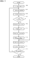
- FIG. 5 is a flowchart of a therapeutic light control program executed by the treatment support device shown in FIG. 1 .
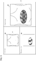
- FIG. 6 shows an example of an image displayed on an image display unit provided on the treatment support device shown in FIG. 1 . Note that in the following description, for convenience of description, for convenience of description, the upper side in FIGS. 1 , 2 , and 6 is referred to as "upper (upper side)," and the lower side is referred to as "lower (lower side)".
- the treatment support device 1 shown in FIG. 1 is a device for emitting excitation light (hereinafter also referred to as "therapeutic light") to a therapeutic agent (RM-1929) which has been injected into the body of the subject ST in which a fluorescent reagent (IR700) and an antibody of an epidermal growth factor receptor (EGFR) is bound to image the fluorescence emitted form the fluorescent reagent (IR700).
- a fluorescent reagent IR700
- EGFR epidermal growth factor receptor
- the treatment support device 1 is provided with a carriage 11 having four wheels 13, an arm mechanism 30 mounted on the front of the carriage 11 in the traveling direction (in the left direction in FIGS. 2 and 3 ) on the upper surface of the carriage 11, a lighting and imaging unit 12 provided on the arm mechanism 30 via the sub-arm 41, and an image display unit 15 as a monitor.
- a handle 14 for moving the carriage 11 is attached.
- a recess 16 for attaching a remote control for remotely operating the treatment support device 1 is formed on the upper surface of the carriage 11.
- a therapeutic light control program is executed (that is, each Step shown in FIG. 5 is executed), a visible image IM1, a fluorescence image IM2, and a composite image IM3 are displayed on the image display unit 15, and the irradiation time and the irradiation intensity of the therapeutic light are controlled (see FIG. 6 ).
- the above-described arm mechanism 30 is provided on the front side of the carriage 11 in the traveling direction.
- the arm mechanism 30 is provided with a first arm member 31 connected, via a hinge portion 33, to a support portion 37 provided on a support 36 erected on the front side of the carriage 11 in the traveling direction.
- the first arm member 31 is swingable with respect to the carriage 11 via the support 36 and the support portion 37 by the action of the hinge portion 33.
- the above-described image display unit 15 is attached to the support 36.
- a second arm member 32 is connected by the hinge portion 34.
- the second arm member 32 is swingable with respect to the first arm member 31 by the action of the hinge portion 34. Therefore, the first arm member 31 and the second arm member 32 can take an imaging posture as shown by the virtual line labelled C in FIG. 2 and a standby posture as shown by the solid line labeled A in FIGS. 1 to 3 .
- the imaging posture the first arm member 31 and the second arm member 32 are opened at a predetermined angle about the hinge portion 34 which is a connecting portion between the first arm member 31 and the second arm member 32.
- the standby posture the first arm member 31 and the second arm member 32 are closely arranged.
- a support portion 43 is connected by a hinge portion 35.
- the support portion 43 is swingable with respect to the second arm member 32 by the action of the hinge portion 35.
- a rotation shaft 42 is supported by the support portion 43.
- the sub-arm 41 supporting the lighting and imaging unit 12 is rotatable about the rotation shaft 42 provided at the tip end of the second arm member 32. For this reason, the lighting and imaging unit 12 is moved by this rotation of the sub-arm 41 between a position on the front side of the carriage 11 in the traveling direction with respect to the arm mechanism 30 for taking the imaging posture or the standby posture as indicated by the solid line labeled A in FIGS. 1 to 3 or as indicated by the virtual line labeled C in FIG. 2 and a position on the rear side of the carriage 11 in the traveling direction with respect to the arm mechanism 30 for taking a posture for moving the carriage 11 as indicated by the virtual line labeled B in FIGS. 2 and 3 .
- the lighting and imaging unit 12 is provided with a light source unit 24, a light source control unit 25, a zoom lens 26, a prism 27, a white light sensor 28, and an excitation light sensor 29.
- the lighting and imaging unit 12 is preferably set so as to be separated from the affected area of the subject ST by about several tens of centimeters.
- the light source unit 24 is provided with a first light source 241, which is a white light source, and a second light source 242, which is an excitation light source.
- a first light source 241 which is a white light source
- a second light source 242 which is an excitation light source.
- the second light source 242 emits excitation light (therapeutic light) to excite the fluorescent reagent (IR700).
- excitation light near-infrared light
- IR700 fluorescent reagent of the therapeutic agent (RM-1929) which has been administered to the subject ST
- the fluorescent reagent (IR700) is excited, the near-infrared light having a peak of about 700 nm is emitted as fluorescence and detected by the excitation light sensor 29.
- the light source control unit 25 has a function of controlling the lighting of the first light source 241. With this function, it is possible to cause the first light source 241 to start emission of white light and stop emission of the white light. Further, the light source control unit 25 has a function of controlling the lighting of the second light source 242, and a function of controlling the amount of light of the second light source 242. These functions control the irradiation time and the irradiation intensity of the therapeutic light emitted from the second light source 242.
- the light source control unit 25 is connected to the control unit 17 for collectively controlling the treatment support device 1, and the first light source 241 and the second light source 242 are controlled in accordance with the instruction from the control unit 17.
- the reflected light (white light) reflected by the subject ST and the fluorescence generated by the fluorescent reagent (IR700) in the subject ST are incident on the zoom lens 26.
- the reflected light (white light) is focused on the white light sensor 28, and the fluorescence is focused on the excitation light sensor 29.
- the light from the zoom lens 26, i.e., the white light and the fluorescence, is incident on the prism 27.
- the prism 27 is configured such that the white light and the fluorescence incident on the prism 27 are separated and that the white light is directed to the white light sensor 28 and the fluorescence is directed to the excitation light sensor 29.
- the white light sensor 28 is an image sensor for detecting a part of the reflected light (white light) separated by the prism 27, and captures, for example, a visible image of the subject ST at the frame rate (30 frames/sec (60 fields/sec)) of the NTSC (National Television System Committee).
- the excitation light sensor 29 is an image sensor for detecting a part of the near-infrared light (fluorescence) separated by the prism 27, and captures the fluorescence image of the subject ST at the frame rate (e.g., 30 frames/sec (60 fields/sec)) of the NTSC.
- the treatment support device 1 is provided with the control unit 17, an image forming unit 18, an image composition unit 19, a storage unit 20, and an operation unit 10. These units are arranged on the carriage 11.
- the control unit 17 is composed of a CPU for executing a logical operation, a ROM for storing an operation program necessary for controlling the device, a RAM for temporarily storing data, etc., at the time of control, and has a function for controlling the entire device.
- the control unit 17 is electrically connected to the light source control unit 25, the image forming unit 18, the image composition unit 19, the image display unit 15, the storage unit 20, and the operation unit 10.
- the control unit 17 reads out the therapeutic light control program stored in the storage unit 20 and controls the above-described units.
- the image forming unit 18 functions as a first imaging unit 181 for acquiring the visible image IM1 by imaging the subject ST irradiated with the white light at the frame rate of the NTSC and a second imaging unit 182 for acquiring the fluorescence image IM2 by imaging the fluorescence generated by the fluorescent reagent (IR700) at the frame rate of the NTSC.
- a first imaging unit 181 for acquiring the visible image IM1 by imaging the subject ST irradiated with the white light at the frame rate of the NTSC
- a second imaging unit 182 for acquiring the fluorescence image IM2 by imaging the fluorescence generated by the fluorescent reagent (IR700) at the frame rate of the NTSC.
- the image composition unit 19 composes the visible image IM1 and the fluorescence image IM2 formed by the image forming unit 18 to form (generate) a composite image IM3.
- the visible image IM1, the fluorescence image IM2, and the composite image IM3 are collectively displayed on the image display unit 15.
- the physician can accurately grasp the treatment position of the subject ST and the treatment effect (i.e., the progress of treatment).
- the storage unit 20 is configured to store a therapeutic light control program executed by the control unit 17, the luminance value, etc., of the fluorescence image IM2 formed by the image forming unit 18.
- the operation unit 10 is a user interface for operating the treatment support device 1.
- the operation unit 10 is configured to be able to emit the light from the light source unit 24, stop the emission of the light, adjust the brightness and the sensitivity, and set the display method, etc., of the image displayed on the image display unit 15.
- the therapeutic light control program executed by the control unit 17 will be described.
- the therapeutic light control program is read from the storage unit 20 and executed by the control unit 17, when the power of the treatment support device 1 is turned on.
- Step S101 when the therapeutic light control program is executed, the control unit 17 controls the light source control unit 25 to turn on the first light source 241.
- the first light source 241 When the first light source 241 is turned on, white light is emitted toward the subject ST.
- Step S101 the processing proceeds to Step S103.
- Step S103 the control unit 17 controls the first imaging unit 181 of the image forming unit 18 and acquires the visible image IM1 from the data of the white light sensor 28 inputted at the frame rate of the NTSC to the image forming unit 18. Upon completion of the processing of Step S103, the processing proceeds to Step S105.
- Step S105 the control unit 17 controls the image composition unit 19 and the image display unit 15, sends the visible image IM1 acquired in Step S103 to the image composition unit 19, and displays the visible image IM1 on the image display unit 15.
- Step S107 the processing proceeds to Step S107.
- Step S107 the control unit 17 determines whether or not the therapeutic light switch (switch for emitting the therapeutic light) of the operation unit 10 is turned on.
- the processing proceeds to Step S109, and when the excitation light switch is turned off (Step S107: NO), the processing proceeds to Step S115.
- Step S109 the control unit 17 controls the light source control unit 25 to turn on the second light source 242.
- the control unit 17 controls the light source control unit 25 to turn on the second light source 242.
- the therapeutic light is emitted toward the subject ST.
- Step S111 the control unit 17 controls the second imaging unit 182 of the image forming unit 18 to acquire the fluorescence image IM2 from the data of the excitation light sensor 29 inputted to the image forming unit 18 at the frame rate of the NTSC. More specifically, in this embodiment, one frame of the fluorescence image IM2 is acquired and stored in the storage unit 20. Upon completion of the processing of Step S111, the processing proceeds to Step S113.
- Step S113 the control unit 17 controls the image composition unit 19 and the image display unit 15 to send the fluorescence image IM2 acquired and stored in Step S111 to the image composition unit 19 and causes the image display unit 15 to display the fluorescence image IM2.
- Step S114 the processing proceeds to Step S114.
- Step S114 the control unit 17 obtains the irradiation intensity (hereinafter referred to as "fluorescence strength P") of the fluorescence from the fluorescence image IM2 acquired and stored in Step S111 and saves (memorizes) it in the storage unit 20. More specifically, in this embodiment, the control unit 17 identifies the pixel receiving the fluorescence in the fluorescence image IM2, obtains the fluorescence strength P (mW) based on the mean luminance value of the pixel, and stores the fluorescence strength P (mW) in the storage unit 20.
- FIG. 7 is a graph showing the relationship between the therapeutic light irradiation time t and the fluorescence strength P. As shown in FIG.
- Step S109 when the therapeutic light is emitted toward the subject ST in Step S109, fluorescence derived from the fluorescent reagent (IR700) in the subject ST is detected. Since the reaction of the fluorescent reagent (IR700) proceeds over time (i.e., the therapeutic light irradiation time t increases), the fluorescence strength P gradually decreases. It is known that when the fluorescence strength P becomes smaller than a predetermined threshold Pth, the amount of change in the fluorescence strength P becomes extremely small. Therefore, in this embodiment, when the fluorescence strength P has become equal to or lower than the predetermined threshold Pth (at the time ts in FIG. 7 ), it is configured to determine that the treatment has been completed (Step S119). In Step S114, the fluorescence strength P of each fluorescence image IM2 is obtained prior to Step S119. Upon completion of the processing of Step S114, the processing proceeds to Step S115.
- Step S115 the control unit 17 controls the image composition unit 19 to superimpose and compose the visible image IM1 acquired in Step S103 and the fluorescence image IM2 acquired in Step S111 to thereby generate a composite image IM3.
- the processing proceeds to Step S117.
- Step S117 the control unit 17 controls the image display unit 15 to cause the image display unit 15 to display the composite image IM3 generated in Step S115. Upon completion of the processing of Step S117, the processing proceeds to Step S119.
- Step S119 the control unit 17 determines whether or not the fluorescence strength P stored in the storage unit 20 in Step S114 has become equal to or less than the predetermined threshold Pth.
- the control unit 17 determines that the treatment has been completed and ends the therapeutic light control program (Step S119: YES), and when the fluorescence strength P has not become equal to or less than the predetermined threshold Pth (Step S119: NO), the processing returns to Step S103 to repeat Steps S103 to S119.
- the physician can accurately grasp the treatment position of the subject ST, the treatment effect (i.e., the progress of treatment), by observing the composite image IM3.
- the fluorescence strength P of each fluorescence image IM2 is obtained in Step S114. It is determined in Step S119 whether or not the fluorescence strength P has become equal to or less than the predetermined threshold Pth.
- the fluorescence strength P has become equal to or less than the predetermined threshold Pth, it is determined that the treatment has been completed and the therapeutic light control program is ended (i.e., the therapeutic light irradiation is stopped). Therefore, unnecessary therapeutic light will not be emitted to the subject ST.
- the therapeutic light is appropriately controlled in accordance with the treatment effect (i.e., the progress of treatment).
- the fluorescence strength P is obtained based on the mean luminance value of the pixel receiving fluorescence in the fluorescence image IM2, but the present invention is not limited to such a configuration.
- the fluorescence strength P may be obtained based on the maximum luminance value in the fluorescence image IM2.
- the therapeutic light control program of this embodiment it is configured such that when the fluorescence strength P has not become equal to or less than the predetermined threshold Pth (Step S119: NO), Steps S103 to S119 are repeated, and therapeutic light is emitted until the fluorescence strength P has become equal to or less than the predetermined threshold Pth (i.e., it is configured to control the irradiation time of the therapeutic light).
- the present invention is not limited to this configuration. For example, in a case where the fluorescence strength P has not yet become equal to or lower than the predetermined threshold Pth (Step S119: NO), the irradiation intensity of the therapeutic light may be increased.
- the reaction of the fluorescent reagent (IR700) proceeds, so that the irradiation time of the therapeutic light (that is, the treatment time) can be shortened.
- the irradiation time and the irradiation intensity of the therapeutic light may be controlled.
- FIG. 8 is a flowchart of a therapeutic light control program shown as Modification 1 of the embodiment. As shown in FIG. 8 , in this modification, it differs from the embodiment in that in Step S119A, the control unit 17 obtains the amount of change ⁇ P in the fluorescence strength from the difference between the fluorescence strength P (n) stored in the storage unit 20 in Step S114 and the fluorescence strength P (n-1) stored in the storage unit 20 in Step S114 one frame earlier, and determines whether or not the amount of change ⁇ P has become equal to or less than the predetermined threshold ⁇ Pth.
- the control unit 17 obtains the amount of change ⁇ P in the fluorescence strength from the difference between the fluorescence strength P (n) stored in the storage unit 20 in Step S114 and the fluorescence strength P (n-1) stored in the storage unit 20 in Step S114 one frame earlier, and determines whether or not the amount of change ⁇ P has become equal to or less than the predetermined threshold ⁇ Pth.
- Step S I 19A YES
- Step S119A NO
- the processing returns to Step S 103 to repeat Steps S103 to S119.
- a treatment support device configured to control therapeutic light emitted toward a treatment site of a subject to whom a therapeutic agent containing a fluorescent dye has been administered and excite the fluorescent dye by means of the therapeutic light to perform treatment, the treatment support device comprising:
- the therapeutic light is appropriately controlled in accordance with the treatment effect (i.e., the progress of treatment), unnecessary therapeutic light will not be emitted to the subject.
- control unit controls at least one of the irradiation time and the irradiation intensity of the therapeutic light such that the intensity of the fluorescence becomes equal to or less than a predetermined threshold.
- the treatment support device as recited in the above-described Item 2, since the therapeutic light is controlled such that the intensity of fluorescence becomes equal to or less than the predetermined threshold, unnecessary therapeutic light irradiation to the subject is assuredly prevented.
- the treatment support device as recited in the above-described Item 1, further comprising:
- the therapeutic light is controlled such that the amount of change in the intensity of the fluorescence becomes equal to or less than the predetermined threshold, unnecessary therapeutic light irradiation to the subject is assuredly prevented.
- the treatment support device as recited in any one of the above-described Items 1 to 3, further comprising:
- the intensity of the fluorescence can be easily detected from the luminance value of the fluorescence image.
- the treatment support device as recited in any one of the above-described Items 1 to 4, wherein the therapeutic light is light having a wavelength of 600 nm to 750 nm.
- a therapeutic light control method configured to control therapeutic light emitted toward a treatment site of a subject to whom a therapeutic agent containing a fluorescent dye has been administered and excite the fluorescent dye by means of the therapeutic light to perform treatment, the therapeutic light control method comprising the steps of:
- the therapeutic light is appropriately controlled in accordance with the treatment effect (that is, the progress of treatment), so that unnecessary therapeutic light will not be emitted to the subj ect.
- the therapeutic light control method as recited in Item 7 since the therapeutic light is controlled such that the intensity of fluorescence becomes equal to or less than the predetermined threshold, unnecessary therapeutic light irradiation to the subject is assuredly prevented.
- the therapeutic light control method as recited in the above-described Item 8, since the therapeutic light is controlled such that the amount of change in the intensity of fluorescence becomes equal to or less than the predetermined threshold, unnecessary therapeutic light irradiation to the subject is assuredly prevented.
- the intensity of the fluorescence can be easily detected from the luminance value of the fluorescence image.
- the therapeutic light control method as recited in any one of the above-described Items 6 to 9, wherein the therapeutic light is light having a wavelength of 600 nm to 750 nm.
- the fluorescent dye can be assuredly excited.
Landscapes
- Health & Medical Sciences (AREA)
- Life Sciences & Earth Sciences (AREA)
- Engineering & Computer Science (AREA)
- Biomedical Technology (AREA)
- General Health & Medical Sciences (AREA)
- Veterinary Medicine (AREA)
- Pathology (AREA)
- Public Health (AREA)
- Animal Behavior & Ethology (AREA)
- Biophysics (AREA)
- Nuclear Medicine, Radiotherapy & Molecular Imaging (AREA)
- Radiology & Medical Imaging (AREA)
- Molecular Biology (AREA)
- Surgery (AREA)
- Medical Informatics (AREA)
- Physics & Mathematics (AREA)
- Heart & Thoracic Surgery (AREA)
- Radiation-Therapy Devices (AREA)
Abstract
Description
- The present invention relates to a treatment support device and a therapeutic light control method.
- In recent years, photoimmunotherapy has attracted attention as one of cancer treatment methods. In this photoimmunotherapy, a therapeutic agent (RM-1929) in which a fluorescent reagent (IR700) and an antibody of an epidermal growth factor receptor (EGFR) are bound is injected into a subject. When the therapeutic agent is injected into the subject, the antibody binds to the surface of cancer cells. In this state, when a subject is irradiated with near-infrared light (therapeutic light) having a wavelength of about 600 nm to about 750 nm for a predetermined period, heat is generated in the therapeutic agent (RM-1929), thereby destroying the cancer cells and detaching the ligand portion, which is a hydrophilic group of IR700, which in turn forms an aggregate and quenches (see, Non-Patent
Documents 1 and 2). - In such photoimmunotherapy, the irradiation time of the therapeutic light is determined in advance based on the treatment site and the light intensity of the therapeutic light, and the therapeutic light is emitted to the treatment site for the irradiation time.
-
- Non Patent Document 1: K. Sato et al., "Photo-induced ligand release from a silicon phthalocyanine dye conjugated with monoclonal antibodies; A mechanism of cancer cell cytotoxicity after near infrared photoimmunotherapy," ACS Central Science, 7 November 2018
- Non Patent Document 2: Shimadzu Corp., First Success in Developing Optical Remote Controller Switches that Kill Only Target Cells - Expected to Contribute to Cancer Treatment with Less Side Effects, [online], [Search on March 10, 2019], Internet <URL: https://WWW.SHIMADZU.CO.JP/news/press/9qbnqud1mddlrfby.html>
- However, in such photoimmunotherapy, the treatment effect (i.e., the progress of treatment) may differ depending on a subject. When therapeutic light is emitted for a predetermined time, in some cases, the therapeutic light may be continuously emitted even though the treatment has already been completed. In this case, the burden on the subject increases. On the other hand, in some cases, the irradiation of the therapeutic light may be stopped even though the treatment has not been completed. In this case, there is a need to perform the treatment again.
- Further, in such photoimmunotherapy, since the burden on the subject increases when the intensity of the therapeutic light is high, there is a demand for lowering the irradiation intensity of the therapeutic light as much as possible.
- The present invention has been made in view of such circumstances. It is an object of the present invention to provide a treatment support device and a therapeutic light control method capable of appropriately controlling therapeutic light in accordance with a treatment effect (that is, the progress of treatment).
- According to a first aspect of the present invention, a treatment support device configured to control therapeutic light emitted toward a treatment site of a subject to whom a therapeutic agent containing a fluorescent dye has been administered and excite the fluorescent dye by means of the therapeutic light to perform treatment, is provided with:
- a light source configured to emit the therapeutic light;
- a control unit configured to control an irradiation time and irradiation intensity of the therapeutic light; and
- a detection unit configured to detect intensity of fluorescence generated from the fluorescent dye, when the therapeutic light is being emitted,
- wherein the control unit controls at least one of the irradiation time and the irradiation intensity of the therapeutic light based on the intensity of the fluorescence.
- According to a second aspect of the present invention, a therapeutic light control method configured to control therapeutic light emitted toward a treatment site of a subject to whom a therapeutic agent containing a fluorescent dye has been administered and excite the fluorescent dye by means of the therapeutic light to perform treatment, includes the steps of:
- emitting the therapeutic light;
- controlling an irradiation time and irradiation intensity of the therapeutic light; and
- detecting intensity of the fluorescence generated from the fluorescent dye, when the therapeutic light is being emitted,
- wherein the step of controlling the therapeutic light controls at least one of the irradiation time and the irradiation intensity of the therapeutic light based on the intensity of the fluorescence.
- According to the present invention, the treatment support device and the therapeutic light control method capable of appropriately controlling therapeutic light in accordance with a treatment effect (i.e., the progress of treatment) can be realized.
-
-
FIG. 1 is a perspective view showing an embodiment of a treatment support device of the present invention. -
FIG. 2 is a side view of the treatment support device shown inFIG. 1 . -
FIG. 3 is a plan view of the treatment support device shown inFIG. 1 . -
FIG. 4 is a block diagram showing a main control system of the treatment support device shown inFIG. 1 . -
FIG. 5 is a flowchart of a therapeutic light control program executed by the treatment support device shown inFIG. 1 . -
FIG. 6 shows an example of an image displayed on an image display unit provided on the treatment support device shown inFIG. 1 . -
FIG. 7 is a graph showing a relationship between a therapeutic light irradiation time t and fluorescence strength P of the treatment support device shown inFIG. 1 . -
FIG. 8 is a flowchart of a therapeutic light control program according toModification 1 of the present invention. - Hereinafter, a treatment support device and a therapeutic light control method according to the present invention will be described in detail based on suitable embodiments shown in the accompanying drawings.
-
FIG. 1 is a perspective view showing an embodiment of a treatment support device of the present invention.FIG. 2 is a side view of the treatment support device shown inFIG. 1 .FIG. 3 is a plan view of the treatment support device shown inFIG. 1 .FIG. 4 is a block diagram showing a main control system of the treatment support device shown inFIG. 1 .FIG. 5 is a flowchart of a therapeutic light control program executed by the treatment support device shown inFIG. 1 .FIG. 6 shows an example of an image displayed on an image display unit provided on the treatment support device shown inFIG. 1 . Note that in the following description, for convenience of description, the upper side inFIGS. 1 ,2 , and6 is referred to as "upper (upper side)," and the lower side is referred to as "lower (lower side)". - The
treatment support device 1 shown inFIG. 1 is a device for emitting excitation light (hereinafter also referred to as "therapeutic light") to a therapeutic agent (RM-1929) which has been injected into the body of the subject ST in which a fluorescent reagent (IR700) and an antibody of an epidermal growth factor receptor (EGFR) is bound to image the fluorescence emitted form the fluorescent reagent (IR700). By using thetreatment support device 1, as will be described later, when performing photoimmunotherapy on the subject ST, it is possible to confirm, for example, the treatment position of the subject ST and the treatment effect (that is, the progress of treatment) and control the irradiation time and the irradiation intensity of the therapeutic light. - The
treatment support device 1 is provided with acarriage 11 having fourwheels 13, anarm mechanism 30 mounted on the front of thecarriage 11 in the traveling direction (in the left direction inFIGS. 2 and 3 ) on the upper surface of thecarriage 11, a lighting andimaging unit 12 provided on thearm mechanism 30 via thesub-arm 41, and animage display unit 15 as a monitor. At the rear portion of thecarriage 11 in the traveling direction, ahandle 14 for moving thecarriage 11 is attached. Arecess 16 for attaching a remote control for remotely operating thetreatment support device 1 is formed on the upper surface of thecarriage 11. - Further, as will be described in detail later, when the power is applied to the
treatment support device 1, a therapeutic light control program is executed (that is, each Step shown inFIG. 5 is executed), a visible image IM1, a fluorescence image IM2, and a composite image IM3 are displayed on theimage display unit 15, and the irradiation time and the irradiation intensity of the therapeutic light are controlled (seeFIG. 6 ). - The above-described
arm mechanism 30 is provided on the front side of thecarriage 11 in the traveling direction. Thearm mechanism 30 is provided with afirst arm member 31 connected, via ahinge portion 33, to asupport portion 37 provided on asupport 36 erected on the front side of thecarriage 11 in the traveling direction. Thefirst arm member 31 is swingable with respect to thecarriage 11 via thesupport 36 and thesupport portion 37 by the action of thehinge portion 33. Note that the above-describedimage display unit 15 is attached to thesupport 36. - At the upper end of the
first arm member 31, asecond arm member 32 is connected by thehinge portion 34. Thesecond arm member 32 is swingable with respect to thefirst arm member 31 by the action of thehinge portion 34. Therefore, thefirst arm member 31 and thesecond arm member 32 can take an imaging posture as shown by the virtual line labelled C inFIG. 2 and a standby posture as shown by the solid line labeled A inFIGS. 1 to 3 . In the imaging posture, thefirst arm member 31 and thesecond arm member 32 are opened at a predetermined angle about thehinge portion 34 which is a connecting portion between thefirst arm member 31 and thesecond arm member 32. In the standby posture, thefirst arm member 31 and thesecond arm member 32 are closely arranged. - At the lower end of the
second arm member 32, asupport portion 43 is connected by ahinge portion 35. Thesupport portion 43 is swingable with respect to thesecond arm member 32 by the action of thehinge portion 35. Arotation shaft 42 is supported by thesupport portion 43. The sub-arm 41 supporting the lighting andimaging unit 12 is rotatable about therotation shaft 42 provided at the tip end of thesecond arm member 32. For this reason, the lighting andimaging unit 12 is moved by this rotation of the sub-arm 41 between a position on the front side of thecarriage 11 in the traveling direction with respect to thearm mechanism 30 for taking the imaging posture or the standby posture as indicated by the solid line labeled A inFIGS. 1 to 3 or as indicated by the virtual line labeled C inFIG. 2 and a position on the rear side of thecarriage 11 in the traveling direction with respect to thearm mechanism 30 for taking a posture for moving thecarriage 11 as indicated by the virtual line labeled B inFIGS. 2 and 3 . - As shown in
FIG. 4 , the lighting andimaging unit 12 is provided with alight source unit 24, a lightsource control unit 25, azoom lens 26, aprism 27, awhite light sensor 28, and anexcitation light sensor 29. When thetreatment support device 1 is used, the lighting andimaging unit 12 is preferably set so as to be separated from the affected area of the subject ST by about several tens of centimeters. - The
light source unit 24 is provided with a firstlight source 241, which is a white light source, and a secondlight source 242, which is an excitation light source. When the firstlight source 241 is turned on, white light is emitted toward the subject ST. The light of the white light is reflected by the subject ST, and the reflected white light is detected by thewhite light sensor 28. - The second
light source 242 emits excitation light (therapeutic light) to excite the fluorescent reagent (IR700). When the secondlight source 242 is turned on, near-infrared light (excitation light) having a wavelength of 600 nm to 750 nm is emitted toward the subject ST, and the fluorescent reagent (IR700) of the therapeutic agent (RM-1929) which has been administered to the subject ST is excited. When the fluorescent reagent (IR700) is excited, the near-infrared light having a peak of about 700 nm is emitted as fluorescence and detected by theexcitation light sensor 29. - The light
source control unit 25 has a function of controlling the lighting of the firstlight source 241. With this function, it is possible to cause the firstlight source 241 to start emission of white light and stop emission of the white light. Further, the lightsource control unit 25 has a function of controlling the lighting of the secondlight source 242, and a function of controlling the amount of light of the secondlight source 242. These functions control the irradiation time and the irradiation intensity of the therapeutic light emitted from the secondlight source 242. The lightsource control unit 25 is connected to thecontrol unit 17 for collectively controlling thetreatment support device 1, and the firstlight source 241 and the secondlight source 242 are controlled in accordance with the instruction from thecontrol unit 17. - The reflected light (white light) reflected by the subject ST and the fluorescence generated by the fluorescent reagent (IR700) in the subject ST are incident on the
zoom lens 26. With thezoom lens 26, the reflected light (white light) is focused on thewhite light sensor 28, and the fluorescence is focused on theexcitation light sensor 29. The light from thezoom lens 26, i.e., the white light and the fluorescence, is incident on theprism 27. Theprism 27 is configured such that the white light and the fluorescence incident on theprism 27 are separated and that the white light is directed to thewhite light sensor 28 and the fluorescence is directed to theexcitation light sensor 29. - The
white light sensor 28 is an image sensor for detecting a part of the reflected light (white light) separated by theprism 27, and captures, for example, a visible image of the subject ST at the frame rate (30 frames/sec (60 fields/sec)) of the NTSC (National Television System Committee). Theexcitation light sensor 29 is an image sensor for detecting a part of the near-infrared light (fluorescence) separated by theprism 27, and captures the fluorescence image of the subject ST at the frame rate (e.g., 30 frames/sec (60 fields/sec)) of the NTSC. - Further, as shown in
FIG. 4 , thetreatment support device 1 is provided with thecontrol unit 17, an image forming unit 18, animage composition unit 19, astorage unit 20, and anoperation unit 10. These units are arranged on thecarriage 11. - The
control unit 17 is composed of a CPU for executing a logical operation, a ROM for storing an operation program necessary for controlling the device, a RAM for temporarily storing data, etc., at the time of control, and has a function for controlling the entire device. Thecontrol unit 17 is electrically connected to the lightsource control unit 25, the image forming unit 18, theimage composition unit 19, theimage display unit 15, thestorage unit 20, and theoperation unit 10. When the power of thetreatment support device 1 is turned on, thecontrol unit 17 reads out the therapeutic light control program stored in thestorage unit 20 and controls the above-described units. - The reflected light (white light) detected by the
white light sensor 28 and the near-infrared light (fluorescence) detected by theexcitation light sensor 29 are inputted to the image forming unit 18. Then, the image forming unit 18 form a visible image IM1 of 24 bits (= 3 × 8) composed of three colors of RGB (red, green, blue) by the reflected light (white light) detected by thewhite light sensor 28. Further, the image forming unit 18 forms a fluorescence image IM2 of 8 bits by the near-infrared light (fluorescence) detected by theexcitation light sensor 29. In this embodiment, the image forming unit 18 functions as a first imaging unit 181 for acquiring the visible image IM1 by imaging the subject ST irradiated with the white light at the frame rate of the NTSC and a second imaging unit 182 for acquiring the fluorescence image IM2 by imaging the fluorescence generated by the fluorescent reagent (IR700) at the frame rate of the NTSC. - The
image composition unit 19 composes the visible image IM1 and the fluorescence image IM2 formed by the image forming unit 18 to form (generate) a composite image IM3. As shown inFIG. 6 , in this embodiment, the visible image IM1, the fluorescence image IM2, and the composite image IM3 are collectively displayed on theimage display unit 15. By observing the composite image IM3, the physician can accurately grasp the treatment position of the subject ST and the treatment effect (i.e., the progress of treatment). - The
storage unit 20 is configured to store a therapeutic light control program executed by thecontrol unit 17, the luminance value, etc., of the fluorescence image IM2 formed by the image forming unit 18. - The
operation unit 10 is a user interface for operating thetreatment support device 1. For example, theoperation unit 10 is configured to be able to emit the light from thelight source unit 24, stop the emission of the light, adjust the brightness and the sensitivity, and set the display method, etc., of the image displayed on theimage display unit 15. - Next, referring to
FIG. 5 , the therapeutic light control program executed by thecontrol unit 17 will be described. The therapeutic light control program is read from thestorage unit 20 and executed by thecontrol unit 17, when the power of thetreatment support device 1 is turned on. - As shown in
FIG. 5 , when the therapeutic light control program is executed, thecontrol unit 17 controls the lightsource control unit 25 to turn on the firstlight source 241. When the firstlight source 241 is turned on, white light is emitted toward the subject ST. Upon completion of the processing of Step S101, the processing proceeds to Step S103. - In Step S103, the
control unit 17 controls the first imaging unit 181 of the image forming unit 18 and acquires the visible image IM1 from the data of thewhite light sensor 28 inputted at the frame rate of the NTSC to the image forming unit 18. Upon completion of the processing of Step S103, the processing proceeds to Step S105. - In Step S105, the
control unit 17 controls theimage composition unit 19 and theimage display unit 15, sends the visible image IM1 acquired in Step S103 to theimage composition unit 19, and displays the visible image IM1 on theimage display unit 15. Upon completion of the processing of Step S105, the processing proceeds to Step S107. - In Step S107, the
control unit 17 determines whether or not the therapeutic light switch (switch for emitting the therapeutic light) of theoperation unit 10 is turned on. When the therapeutic light switch is turned on (Step S107: YES), the processing proceeds to Step S109, and when the excitation light switch is turned off (Step S107: NO), the processing proceeds to Step S115. - In Step S109, the
control unit 17 controls the lightsource control unit 25 to turn on the secondlight source 242. When the secondlight source 242 is turned on, the therapeutic light is emitted toward the subject ST. Upon completion of the processing of Step S109, the processing proceeds to Step S111. - In Step S111, the
control unit 17 controls the second imaging unit 182 of the image forming unit 18 to acquire the fluorescence image IM2 from the data of theexcitation light sensor 29 inputted to the image forming unit 18 at the frame rate of the NTSC. More specifically, in this embodiment, one frame of the fluorescence image IM2 is acquired and stored in thestorage unit 20. Upon completion of the processing of Step S111, the processing proceeds to Step S113. - In Step S113, the
control unit 17 controls theimage composition unit 19 and theimage display unit 15 to send the fluorescence image IM2 acquired and stored in Step S111 to theimage composition unit 19 and causes theimage display unit 15 to display the fluorescence image IM2. Upon completion of the processing of Step S113, the processing proceeds to Step S114. - In Step S114, the
control unit 17 obtains the irradiation intensity (hereinafter referred to as "fluorescence strength P") of the fluorescence from the fluorescence image IM2 acquired and stored in Step S111 and saves (memorizes) it in thestorage unit 20. More specifically, in this embodiment, thecontrol unit 17 identifies the pixel receiving the fluorescence in the fluorescence image IM2, obtains the fluorescence strength P (mW) based on the mean luminance value of the pixel, and stores the fluorescence strength P (mW) in thestorage unit 20.FIG. 7 is a graph showing the relationship between the therapeutic light irradiation time t and the fluorescence strength P. As shown inFIG. 7 , when the therapeutic light is emitted toward the subject ST in Step S109, fluorescence derived from the fluorescent reagent (IR700) in the subject ST is detected. Since the reaction of the fluorescent reagent (IR700) proceeds over time (i.e., the therapeutic light irradiation time t increases), the fluorescence strength P gradually decreases. It is known that when the fluorescence strength P becomes smaller than a predetermined threshold Pth, the amount of change in the fluorescence strength P becomes extremely small. Therefore, in this embodiment, when the fluorescence strength P has become equal to or lower than the predetermined threshold Pth (at the time ts inFIG. 7 ), it is configured to determine that the treatment has been completed (Step S119). In Step S114, the fluorescence strength P of each fluorescence image IM2 is obtained prior to Step S119. Upon completion of the processing of Step S114, the processing proceeds to Step S115. - In Step S115, the
control unit 17 controls theimage composition unit 19 to superimpose and compose the visible image IM1 acquired in Step S103 and the fluorescence image IM2 acquired in Step S111 to thereby generate a composite image IM3. Upon completion of the processing of Step S115, the processing proceeds to Step S117. - In Step S117, the
control unit 17 controls theimage display unit 15 to cause theimage display unit 15 to display the composite image IM3 generated in Step S115. Upon completion of the processing of Step S117, the processing proceeds to Step S119. - In Step S119, the
control unit 17 determines whether or not the fluorescence strength P stored in thestorage unit 20 in Step S114 has become equal to or less than the predetermined threshold Pth. When the fluorescence strength P has become equal to or less than the predetermined threshold Pth, thecontrol unit 17 determines that the treatment has been completed and ends the therapeutic light control program (Step S119: YES), and when the fluorescence strength P has not become equal to or less than the predetermined threshold Pth (Step S119: NO), the processing returns to Step S103 to repeat Steps S103 to S119. - As described above, when the composite image IM3 is obtained by the
treatment support device 1 of this embodiment (i.e., when the therapeutic light control program is executed), the physician can accurately grasp the treatment position of the subject ST, the treatment effect (i.e., the progress of treatment), by observing the composite image IM3. Further, in this embodiment, the fluorescence strength P of each fluorescence image IM2 is obtained in Step S114. It is determined in Step S119 whether or not the fluorescence strength P has become equal to or less than the predetermined threshold Pth. When the fluorescence strength P has become equal to or less than the predetermined threshold Pth, it is determined that the treatment has been completed and the therapeutic light control program is ended (i.e., the therapeutic light irradiation is stopped). Therefore, unnecessary therapeutic light will not be emitted to the subject ST. In other words, the therapeutic light is appropriately controlled in accordance with the treatment effect (i.e., the progress of treatment). - Although the embodiment of the present invention has been described above, the present invention is not limited to the configuration of the embodiment described above, and various modifications can be made within the scope of the technical concept.
- For example, in this embodiment, it is configured such that the fluorescence strength P is obtained based on the mean luminance value of the pixel receiving fluorescence in the fluorescence image IM2, but the present invention is not limited to such a configuration. For example, the fluorescence strength P may be obtained based on the maximum luminance value in the fluorescence image IM2.
- Further, in the therapeutic light control program of this embodiment, it is configured such that when the fluorescence strength P has not become equal to or less than the predetermined threshold Pth (Step S119: NO), Steps S103 to S119 are repeated, and therapeutic light is emitted until the fluorescence strength P has become equal to or less than the predetermined threshold Pth (i.e., it is configured to control the irradiation time of the therapeutic light). However, the present invention is not limited to this configuration. For example, in a case where the fluorescence strength P has not yet become equal to or lower than the predetermined threshold Pth (Step S119: NO), the irradiation intensity of the therapeutic light may be increased. As described above, when the irradiation intensity of the therapeutic light is increased, the reaction of the fluorescent reagent (IR700) proceeds, so that the irradiation time of the therapeutic light (that is, the treatment time) can be shortened. Thus, in this embodiment, at least one of the irradiation time and the irradiation intensity of the therapeutic light may be controlled.
-
FIG. 8 is a flowchart of a therapeutic light control program shown asModification 1 of the embodiment. As shown inFIG. 8 , in this modification, it differs from the embodiment in that in Step S119A, thecontrol unit 17 obtains the amount of change ΔP in the fluorescence strength from the difference between the fluorescence strength P(n) stored in thestorage unit 20 in Step S114 and the fluorescence strength P(n-1) stored in thestorage unit 20 in Step S114 one frame earlier, and determines whether or not the amount of change ΔP has become equal to or less than the predetermined threshold ΔPth. When the amount of change ΔP in the fluorescence strength P has become equal to or less than the predetermined threshold ΔPth, thecontrol unit 17 determines that the treatment has been completed and ends the therapeutic light control program (Step S I 19A: YES). On the other hand, when the amount of change ΔP in the fluorescence strength P has not yet become equal to or less than the predetermined threshold ΔPth (Step S119A: NO), the processing returns to StepS 103 to repeat Steps S103 to S119. - In this manner, in this modification, attention is paid to the amount of change ΔP in the fluorescence strength P, and when the amount of change ΔP in the fluorescence strength P has become equal to or less than the predetermined threshold APth (that is, when the amount of change ΔP has become small), it is determined that the treatment has been completed, and the therapeutic light control program is finished (that is, the illumination of therapeutic light is stopped). Therefore, unnecessary therapeutic light will not be emitted to the subject ST. In other words, therapeutic light is appropriately controlled in accordance with the treatment effect (i.e., the progress of treatment).
- It should be noted that the embodiments disclosed herein are illustrative in all respects and should not be considered limiting. The scope of the present invention is indicated by claims and not by the above-described descriptions, and is intended to include all modifications within the meanings and scopes equivalent to the claims.
- A treatment support device configured to control therapeutic light emitted toward a treatment site of a subject to whom a therapeutic agent containing a fluorescent dye has been administered and excite the fluorescent dye by means of the therapeutic light to perform treatment, the treatment support device comprising:
- a light source configured to emit the therapeutic light;
- a control unit configured to control an irradiation time and irradiation intensity of the therapeutic light; and
- a detection unit configured to detect intensity of fluorescence generated from the fluorescent dye, when the therapeutic light is being emitted,
- wherein the control unit controls at least one of the irradiation time and the irradiation intensity of the therapeutic light based on the intensity of the fluorescence.
- According to the treatment support device described in
Item 1, since the therapeutic light is appropriately controlled in accordance with the treatment effect (i.e., the progress of treatment), unnecessary therapeutic light will not be emitted to the subject. - The treatment support device as recited in the above-described
Item 1,
wherein the control unit controls at least one of the irradiation time and the irradiation intensity of the therapeutic light such that the intensity of the fluorescence becomes equal to or less than a predetermined threshold. - According to the treatment support device as recited in the above-described Item 2, since the therapeutic light is controlled such that the intensity of fluorescence becomes equal to or less than the predetermined threshold, unnecessary therapeutic light irradiation to the subject is assuredly prevented.
- The treatment support device as recited in the above-described
Item 1, further comprising: - a storage unit configured to sequentially store the intensity of the fluorescence,
- wherein the control unit
- calculates an amount of change in the intensity of the fluorescence per predetermined time based on the intensity of the fluorescence stored in the storage unit, and
- controls at least one of the irradiation time and the irradiation intensity of the therapeutic light such that the amount of change becomes equal to or less than a predetermined threshold.
- According to the treatment support device as recited in the above-described Item 3, since the therapeutic light is controlled such that the amount of change in the intensity of the fluorescence becomes equal to or less than the predetermined threshold, unnecessary therapeutic light irradiation to the subject is assuredly prevented.
- The treatment support device as recited in any one of the above-described
Items 1 to 3, further comprising: - an imaging unit configured to acquire a fluorescence image by imaging the fluorescence generated from the fluorescent dye, when the therapeutic light is being emitted,
- wherein the detection unit detects the intensity of the fluorescence based on a luminance value of the fluorescence image.
- According to the treatment support device as recited in the above-described Item 4, the intensity of the fluorescence can be easily detected from the luminance value of the fluorescence image.
- The treatment support device as recited in any one of the above-described
Items 1 to 4,
wherein the therapeutic light is light having a wavelength of 600 nm to 750 nm. - According to the treatment support device as recited in the above-described Item 5, it is possible to assuredly excite the fluorescent dye.
- A therapeutic light control method configured to control therapeutic light emitted toward a treatment site of a subject to whom a therapeutic agent containing a fluorescent dye has been administered and excite the fluorescent dye by means of the therapeutic light to perform treatment, the therapeutic light control method comprising the steps of:
- emitting the therapeutic light;
- controlling an irradiation time and irradiation intensity of the therapeutic light; and
- detecting intensity of fluorescence generated from the fluorescent dye, when the therapeutic light is being emitted,
- wherein the step of controlling the therapeutic light controls at least one of the irradiation time and the irradiation intensity of the therapeutic light based on the intensity of the fluorescence.
- According to the therapeutic light control method of the above-described Item 6, the therapeutic light is appropriately controlled in accordance with the treatment effect (that is, the progress of treatment), so that unnecessary therapeutic light will not be emitted to the subj ect.
- The therapeutic light control method as recited in the above-described Item 6,
wherein the step of controlling the therapeutic light controls at least one of the irradiation time and the irradiation intensity of the therapeutic light such that the intensity of fluorescence becomes equal to or less than a predetermined threshold. - According to the therapeutic light control method as recited in Item 7, since the therapeutic light is controlled such that the intensity of fluorescence becomes equal to or less than the predetermined threshold, unnecessary therapeutic light irradiation to the subject is assuredly prevented.
- The therapeutic light control method as recited in the above-described Item 6, further comprising the step of:
- sequentially storing the intensity of the fluorescence,
- wherein the step of controlling the therapeutic light control
- calculates an amount of change in the intensity of the fluorescence per predetermined time based on the intensity of the fluorescence stored in the storage unit, and
- controls at least one of the irradiation time and the irradiation intensity of the therapeutic light such that the amount of change becomes equal to or less than a predetermined threshold.
- According to the therapeutic light control method as recited in the above-described Item 8, since the therapeutic light is controlled such that the amount of change in the intensity of fluorescence becomes equal to or less than the predetermined threshold, unnecessary therapeutic light irradiation to the subject is assuredly prevented.
- The therapeutic light control method as recited in any one of the above-described Items 6 to 8, further comprising the step of:
- acquiring a fluorescence image by imaging the fluorescence generated from the fluorescent dye, when the therapeutic light is being emitted,
- wherein the step of detecting the intensity of the fluorescence detects the intensity of the fluorescence based on a luminance value of the fluorescence image.
- According to the therapeutic light control method as recited in the above-described Item 9, the intensity of the fluorescence can be easily detected from the luminance value of the fluorescence image.
- The therapeutic light control method as recited in any one of the above-described Items 6 to 9,
wherein the therapeutic light is light having a wavelength of 600 nm to 750 nm. - According to the therapeutic light control method as recited in the above-described
Item 10, the fluorescent dye can be assuredly excited. -
- 1:
- Treatment support device
- 10:
- Operation Unit
- 11:
- Carriage
- 12:
- Imaging unit
- 13:
- Wheel
- 14:
- Handle
- 15:
- Image display unit
- 16:
- Recess
- 17:
- Control Unit
- 18:
- Image forming unit
- 19:
- Image composition unit
- 20:
- Storage unit
- 24:
- Light source unit
- 25:
- Light source control unit
- 26:
- Zoom lens
- 27:
- Prism
- 28:
- White light sensor
- 29:
- Excitation light sensor
- 30:
- Arm mechanism
- 31:
- First arm member
- 32:
- Second arm member
- 33:
- Hinge portion
- 34:
- Hinge portion
- 35:
- Hinge portion
- 36:
- Support
- 37:
- Support portion
- 41:
- Sub-arm
- 42:
- Rotation shaft
- 43:
- Support portion
- 181:
- First imaging unit
- 182:
- Second imaging unit
- 241:
- First light source
- 242:
- Second light source
- IM1:
- Visible image
- IM2:
- Fluorescence image
- IM3:
- Composite image
- ST:
- Subject
Claims (10)
- A treatment support device configured to control therapeutic light emitted toward a treatment site of a subject to whom a therapeutic agent containing a fluorescent dye has been administered and excite the fluorescent dye by means of the therapeutic light to perform treatment, the treatment support device comprising:a light source configured to emit the therapeutic light;a control unit configured to control an irradiation time and irradiation intensity of the therapeutic light; anda detection unit configured to detect intensity of fluorescence generated from the fluorescent dye, when the therapeutic light is being emitted,wherein the control unit controls at least one of the irradiation time and the irradiation intensity of the therapeutic light based on the intensity of the fluorescence.
- The treatment support device as recited in claim 1,
wherein the control unit controls at least one of the irradiation time and the irradiation intensity of the therapeutic light such that the intensity of the fluorescence becomes equal to or less than a predetermined threshold. - The treatment support device as recited in claim 1, further comprising:a storage unit configured to sequentially store the intensity of the fluorescence,wherein the control unitcalculates an amount of change in the intensity of the fluorescence per predetermined time based on the intensity of the fluorescence stored in the storage unit, andcontrols at least one of the irradiation time and the irradiation intensity of the therapeutic light such that the amount of change becomes equal to or less than a predetermined threshold.
- The treatment support device as recited in any one of claims 1 to 3, further comprising:an imaging unit configured to acquire a fluorescence image by imaging the fluorescence generated from the fluorescent dye, when the therapeutic light is being emitted,wherein the detection unit detects the intensity of the fluorescence based on a luminance value of the fluorescence image.
- The treatment support device as recited in any one of claims 1 to 4,
wherein the therapeutic light is light having a wavelength of 600 nm to 750 nm. - A therapeutic light control method configured to control therapeutic light emitted toward a treatment site of a subject to whom a therapeutic agent containing a fluorescent dye has been administered and excite the fluorescent dye by means of the therapeutic light to perform treatment, the therapeutic light control method comprising the steps of:emitting the therapeutic light;controlling an irradiation time and irradiation intensity of the therapeutic light; anddetecting intensity of fluorescence generated from the fluorescent dye, when the therapeutic light is being emitted,wherein the step of controlling the therapeutic light controls at least one of the irradiation time and the irradiation intensity of the therapeutic light based on the intensity of the fluorescence.
- The therapeutic light control method as recited in claim 6,
wherein the step of controlling the therapeutic light controls at least one of the irradiation time and the irradiation intensity of the therapeutic light such that the intensity of fluorescence becomes equal to or less than a predetermined threshold. - The therapeutic light control method as recited in claim 6, further comprising the step of:sequentially storing the intensity of the fluorescence,wherein the step of controlling the therapeutic light controlcalculates an amount of change in the intensity of the fluorescence per predetermined time based on the intensity of the fluorescence stored in the storage unit, andcontrols at least one of the irradiation time and the irradiation intensity of the therapeutic light such that the amount of change becomes equal to or less than a predetermined threshold.
- The therapeutic light control method as recited in any one of claims 6 to 8, further comprising the step of:acquiring a fluorescence image by imaging the fluorescence generated from the fluorescent dye, when the therapeutic light is being emitted,wherein the step of detecting the intensity of the fluorescence detects the intensity of the fluorescence based on a luminance value of the fluorescence image.
- The therapeutic light control method as recited in any one of claims 6 to 9, wherein the therapeutic light is light having a wavelength of 600 nm to 750 nm.
Applications Claiming Priority (1)
| Application Number | Priority Date | Filing Date | Title |
|---|---|---|---|
| PCT/JP2019/033560 WO2021038726A1 (en) | 2019-08-27 | 2019-08-27 | Treatment support device and therapeutic light control method |
Publications (2)
| Publication Number | Publication Date |
|---|---|
| EP4023287A1 true EP4023287A1 (en) | 2022-07-06 |
| EP4023287A4 EP4023287A4 (en) | 2023-05-17 |
Family
ID=74684710
Family Applications (1)
| Application Number | Title | Priority Date | Filing Date |
|---|---|---|---|
| EP19943649.4A Withdrawn EP4023287A4 (en) | 2019-08-27 | 2019-08-27 | TREATMENT SUPPORT DEVICE AND THERAPEUTIC LIGHT CONTROL METHOD |
Country Status (5)
| Country | Link |
|---|---|
| US (1) | US20220288411A1 (en) |
| EP (1) | EP4023287A4 (en) |
| JP (1) | JP7435611B2 (en) |
| CN (1) | CN114286709B (en) |
| WO (1) | WO2021038726A1 (en) |
Families Citing this family (4)
| Publication number | Priority date | Publication date | Assignee | Title |
|---|---|---|---|---|
| DE102020117579A1 (en) * | 2020-07-03 | 2022-01-05 | Hoya Corporation | Endoscopic lighting system for a fluorescent agent |
| WO2022061366A1 (en) * | 2020-09-18 | 2022-03-24 | Arizona Board Of Regents On Behalf Of The University Of Arizona | Monitoring of autonomic nervous system activity through sweat pore activation |
| JP7476755B2 (en) * | 2020-10-19 | 2024-05-01 | 株式会社島津製作所 | Treatment Support Device |
| WO2023112089A1 (en) * | 2021-12-13 | 2023-06-22 | 株式会社島津製作所 | Treatment assistance device |
Family Cites Families (13)
| Publication number | Priority date | Publication date | Assignee | Title |
|---|---|---|---|---|
| CN101677751B (en) * | 2007-05-22 | 2012-06-27 | 奥林巴斯株式会社 | Encapsulated medical device and encapsulated medical system |
| JP2009112804A (en) * | 2007-10-18 | 2009-05-28 | Minato Ikagaku Kk | Blue light stimulation device for promoting internal production of igf-1, and method thereof |
| JP2011167344A (en) * | 2010-02-18 | 2011-09-01 | Fujifilm Corp | Medical device system for pdt, electronic endoscope system, surgical microscope system, and treatment light irradiation distribution control method |
| JP5719159B2 (en) * | 2010-03-15 | 2015-05-13 | ソニー株式会社 | Evaluation device |
| CN103153155B (en) * | 2011-03-15 | 2014-09-10 | 奥林巴斯医疗株式会社 | Medical device |
| CN103608662B (en) * | 2011-06-29 | 2016-09-28 | 京都府公立大学法人 | The identification device of tumor locus and recognition methods |
| CA2841120C (en) | 2011-07-11 | 2020-10-27 | The United States Of America, As Represented By The Secretary, Department Of Health And Human Services | Antibody-ir700 conjugates for photodynamic therapy |
| JP2014221117A (en) * | 2013-05-13 | 2014-11-27 | 株式会社アライ・メッドフォトン研究所 | Therapy progress degree monitoring device and method for therapy progress degree monitoring |
| WO2016151888A1 (en) * | 2015-03-26 | 2016-09-29 | オリンパス株式会社 | Image processing device |
| JP6432533B2 (en) * | 2016-01-14 | 2018-12-05 | 株式会社島津製作所 | Imaging device |
| JP6897483B2 (en) | 2017-10-18 | 2021-06-30 | 株式会社ニコン | Light irradiation device, light irradiation program, and driving method of the light irradiation device |
| KR101903423B1 (en) * | 2018-02-20 | 2018-10-04 | 한국광기술원 | Hybrid imaging system for photodiagnosis and phototherapy |
| JP2019048111A (en) * | 2018-11-07 | 2019-03-28 | 株式会社島津製作所 | Imaging method |
-
2019
- 2019-08-27 CN CN201980099753.3A patent/CN114286709B/en active Active
- 2019-08-27 US US17/637,872 patent/US20220288411A1/en active Pending
- 2019-08-27 EP EP19943649.4A patent/EP4023287A4/en not_active Withdrawn
- 2019-08-27 JP JP2021541846A patent/JP7435611B2/en active Active
- 2019-08-27 WO PCT/JP2019/033560 patent/WO2021038726A1/en not_active Ceased
Also Published As
| Publication number | Publication date |
|---|---|
| EP4023287A4 (en) | 2023-05-17 |
| CN114286709B (en) | 2025-06-03 |
| US20220288411A1 (en) | 2022-09-15 |
| CN114286709A (en) | 2022-04-05 |
| WO2021038726A1 (en) | 2021-03-04 |
| JPWO2021038726A1 (en) | 2021-03-04 |
| JP7435611B2 (en) | 2024-02-21 |
Similar Documents
| Publication | Publication Date | Title |
|---|---|---|
| EP4023287A1 (en) | Treatment support device and therapeutic light control method | |
| US7798955B2 (en) | Image generating device for generating a fluorescence image | |
| US20220109783A1 (en) | Systems, methods, and devices for providing illumination in an endoscopic imaging environment | |
| JP2024038065A (en) | Imaging method | |
| JPH09308604A (en) | Fluorescence detector | |
| CN112367898B (en) | Endoscope device and method for operating endoscope device | |
| EP3185805B1 (en) | System for fluorescence-based laser ablation | |
| EP3632291A1 (en) | Observation system and light source control apparatus | |
| EP2662017B1 (en) | Scanning laser optometry device | |
| JP7306810B2 (en) | MICROSCOPE SYSTEM CONTROL METHOD, MICROSCOPE SYSTEM, PROGRAM, RECORDING MEDIUM | |
| US11684238B2 (en) | Control device and medical observation system | |
| JPH10225436A (en) | Fluorescence detector | |
| JP2000325296A (en) | Fluorescent detector | |
| EP3943997B1 (en) | Medical control apparatus and medical observation apparatus | |
| WO2013005765A1 (en) | Microscope device | |
| CN117838020A (en) | Endoscopic system and light therapy | |
| JP7200755B2 (en) | IMAGING DEVICE AND METHOD OF OPERATION OF IMAGING DEVICE | |
| JP2018124664A (en) | Image processing apparatus and imaging apparatus |
Legal Events
| Date | Code | Title | Description |
|---|---|---|---|
| STAA | Information on the status of an ep patent application or granted ep patent |
Free format text: STATUS: THE INTERNATIONAL PUBLICATION HAS BEEN MADE |
|
| PUAI | Public reference made under article 153(3) epc to a published international application that has entered the european phase |
Free format text: ORIGINAL CODE: 0009012 |
|
| STAA | Information on the status of an ep patent application or granted ep patent |
Free format text: STATUS: REQUEST FOR EXAMINATION WAS MADE |
|
| 17P | Request for examination filed |
Effective date: 20220310 |
|
| AK | Designated contracting states |
Kind code of ref document: A1 Designated state(s): AL AT BE BG CH CY CZ DE DK EE ES FI FR GB GR HR HU IE IS IT LI LT LU LV MC MK MT NL NO PL PT RO RS SE SI SK SM TR |
|
| DAV | Request for validation of the european patent (deleted) | ||
| DAX | Request for extension of the european patent (deleted) | ||
| A4 | Supplementary search report drawn up and despatched |
Effective date: 20230417 |
|
| RIC1 | Information provided on ipc code assigned before grant |
Ipc: A61B 5/00 20060101ALI20230411BHEP Ipc: A61B 10/00 20060101ALI20230411BHEP Ipc: A61N 5/06 20060101AFI20230411BHEP |
|
| GRAP | Despatch of communication of intention to grant a patent |
Free format text: ORIGINAL CODE: EPIDOSNIGR1 |
|
| STAA | Information on the status of an ep patent application or granted ep patent |
Free format text: STATUS: GRANT OF PATENT IS INTENDED |
|
| INTG | Intention to grant announced |
Effective date: 20250123 |
|
| STAA | Information on the status of an ep patent application or granted ep patent |
Free format text: STATUS: THE APPLICATION IS DEEMED TO BE WITHDRAWN |
|
| 18D | Application deemed to be withdrawn |
Effective date: 20250524 |