EP4023117A1 - Soda maker having convenient gas intake and discharge - Google Patents
Soda maker having convenient gas intake and discharge Download PDFInfo
- Publication number
- EP4023117A1 EP4023117A1 EP20859261.8A EP20859261A EP4023117A1 EP 4023117 A1 EP4023117 A1 EP 4023117A1 EP 20859261 A EP20859261 A EP 20859261A EP 4023117 A1 EP4023117 A1 EP 4023117A1
- Authority
- EP
- European Patent Office
- Prior art keywords
- gas discharge
- gas
- engaged
- valve
- rod
- Prior art date
- Legal status (The legal status is an assumption and is not a legal conclusion. Google has not performed a legal analysis and makes no representation as to the accuracy of the status listed.)
- Granted
Links
Images


Classifications
-
- A—HUMAN NECESSITIES
- A23—FOODS OR FOODSTUFFS; TREATMENT THEREOF, NOT COVERED BY OTHER CLASSES
- A23L—FOODS, FOODSTUFFS OR NON-ALCOHOLIC BEVERAGES, NOT OTHERWISE PROVIDED FOR; PREPARATION OR TREATMENT THEREOF
- A23L2/00—Non-alcoholic beverages; Dry compositions or concentrates therefor; Preparation or treatment thereof
- A23L2/52—Adding ingredients
- A23L2/54—Mixing with gases
-
- A—HUMAN NECESSITIES
- A47—FURNITURE; DOMESTIC ARTICLES OR APPLIANCES; COFFEE MILLS; SPICE MILLS; SUCTION CLEANERS IN GENERAL
- A47J—KITCHEN EQUIPMENT; COFFEE MILLS; SPICE MILLS; APPARATUS FOR MAKING BEVERAGES
- A47J31/00—Apparatus for making beverages
- A47J31/005—Portable or compact beverage making apparatus, e.g. for travelling, for use in automotive vehicles
-
- A—HUMAN NECESSITIES
- A47—FURNITURE; DOMESTIC ARTICLES OR APPLIANCES; COFFEE MILLS; SPICE MILLS; SUCTION CLEANERS IN GENERAL
- A47J—KITCHEN EQUIPMENT; COFFEE MILLS; SPICE MILLS; APPARATUS FOR MAKING BEVERAGES
- A47J31/00—Apparatus for making beverages
- A47J31/44—Parts or details or accessories of beverage-making apparatus
- A47J31/46—Dispensing spouts, pumps, drain valves or like liquid transporting devices
- A47J31/461—Valves, e.g. drain valves
-
- B—PERFORMING OPERATIONS; TRANSPORTING
- B01—PHYSICAL OR CHEMICAL PROCESSES OR APPARATUS IN GENERAL
- B01F—MIXING, e.g. DISSOLVING, EMULSIFYING OR DISPERSING
- B01F23/00—Mixing according to the phases to be mixed, e.g. dispersing or emulsifying
- B01F23/20—Mixing gases with liquids
- B01F23/23—Mixing gases with liquids by introducing gases into liquid media, e.g. for producing aerated liquids
- B01F23/236—Mixing gases with liquids by introducing gases into liquid media, e.g. for producing aerated liquids specially adapted for aerating or carbonating beverages
- B01F23/2361—Mixing gases with liquids by introducing gases into liquid media, e.g. for producing aerated liquids specially adapted for aerating or carbonating beverages within small containers, e.g. within bottles
-
- B—PERFORMING OPERATIONS; TRANSPORTING
- B01—PHYSICAL OR CHEMICAL PROCESSES OR APPARATUS IN GENERAL
- B01F—MIXING, e.g. DISSOLVING, EMULSIFYING OR DISPERSING
- B01F23/00—Mixing according to the phases to be mixed, e.g. dispersing or emulsifying
- B01F23/20—Mixing gases with liquids
- B01F23/23—Mixing gases with liquids by introducing gases into liquid media, e.g. for producing aerated liquids
- B01F23/237—Mixing gases with liquids by introducing gases into liquid media, e.g. for producing aerated liquids characterised by the physical or chemical properties of gases or vapours introduced in the liquid media
- B01F23/2376—Mixing gases with liquids by introducing gases into liquid media, e.g. for producing aerated liquids characterised by the physical or chemical properties of gases or vapours introduced in the liquid media characterised by the gas being introduced
- B01F23/23762—Carbon dioxide
- B01F23/237621—Carbon dioxide in beverages
-
- A—HUMAN NECESSITIES
- A47—FURNITURE; DOMESTIC ARTICLES OR APPLIANCES; COFFEE MILLS; SPICE MILLS; SUCTION CLEANERS IN GENERAL
- A47J—KITCHEN EQUIPMENT; COFFEE MILLS; SPICE MILLS; APPARATUS FOR MAKING BEVERAGES
- A47J31/00—Apparatus for making beverages
- A47J31/44—Parts or details or accessories of beverage-making apparatus
- A47J31/4403—Constructional details
Definitions
- the present Patent relates to a soda maker.
- a soda maker comprises a main unit and an auxiliary unit.
- the main unit comprises a housing, a base, a carbon dioxide cylinder provided within the housing, and a gas intake main body provided at the top of the carbon dioxide cylinder.
- the auxiliary unit comprises an outer casing, an auxiliary unit main body, a water bottle coupler, a tapered ring, and a soda bottle.
- the auxiliary unit main body is provided with a gas discharge valve.
- the outer casing is connected with the housing.
- the gas intake main body is connected with the gas intake assembly on the auxiliary unit main body, and a gas rod connected with the gas intake assembly extends into the soda bottle.
- the present Patent aims to provide a soda maker having convenient gas intake and discharge, which has the characteristics of convenient gas intake and discharge.
- a soda maker having convenient gas intake and discharge which comprises a main unit and an auxiliary unit, wherein the main unit comprises a housing, a base, a carbon dioxide cylinder provided within the housing, a gas intake main body provided at the top of the carbon dioxide cylinder, a gas intake support, a gas intake connecting rod, and a locking engagement member, the gas intake connecting rod is pivoted with the gas intake main body, the locking engagement member is pivoted with the gas intake support, the locking engagement member is engaged with the gas intake connecting rod;
- the auxiliary unit comprises an outer casing, an auxiliary unit main body, a water bottle coupler, a tapered ring, and a soda bottle, the auxiliary unit main body is provided with a gas discharge valve and a switch valve, the outer casing is connected with the housing, the gas intake main body is communicated with a gas intake assembly on the auxiliary unit main body, and a gas rod connected with the gas intake assembly extends into the soda bottle; wherein the housing is provided with an installation hole;
- the gas discharge valve comprises a gas discharge valve body, a gas discharge valve nut, a gas discharge valve rod, a gas discharge valve core and a pressure spring which are provided on the auxiliary unit main body, the closed end of the gas discharge valve body is provided with a valve core base and is connected with the cavity of the auxiliary unit main body, and the gas discharge valve body is provided with radial gas discharge holes;
- the operation positioning blind hole and the gas discharge positioning blind hole are communicated through an arc-shaped guide groove.
- the connecting part is located in the installation hole, and there is a gap between the connecting part and the installation hole.
- the switch valve comprises a switch valve body provided on the auxiliary unit main body, a switch valve core base provided in the switch valve body, a switch valve rod, a valve core, a pressure spring, a switch nut and a safety gas discharge device communicated with the switch valve body;
- the safety gas discharge device comprises a gas discharge cavity, a safety valve core base provided at the bottom of the gas discharge cavity, a pressure relief hole, a safety valve core, a valve rod, a pressure spring and a plug;
- the safety valve core is provided on the head of the valve rod, the safety valve core is engaged with the safety valve core base, the plug is screwed with the internal thread part at the upper part of the gas discharge cavity, and the pressure spring is engaged with the head of the valve rod and the internal counterbore on the plug.
- the present Patent relates to a soda maker having convenient gas intake and discharge.
- the structure of the present Patent enables the auxiliary unit to rotate by a specific angle and stop after an operation has ended, such that automatic gas discharge is achieved before a soda bottle removal step is performed, thereby providing operational convenience.
- a soda maker having convenient gas intake and discharge comprises a main unit 1 and an auxiliary unit 2.
- the main unit 1 comprises a housing 3, a base 4, a carbon dioxide cylinder provided within the housing, a gas intake main body 5 provided at the top of the carbon dioxide cylinder, a gas intake support 6, a gas intake connecting rod 7, and a locking engagement member 8.
- the gas intake connecting rod 7 is pivoted with the gas intake main body 5.
- the locking engagement member 8 is pivoted with the gas intake support 6.
- the locking engagement member 8 is engaged with the gas intake connecting rod 7.
- the auxiliary unit 2 comprises an outer casing 9, an auxiliary unit main body 10, a water bottle coupler 11, a tapered ring 12, and a soda bottle 13.
- the tapered ring 12 is provided between the auxiliary unit main body 10 and the water bottle coupler 11.
- the auxiliary unit main body 10 and the water bottle coupler 11 are fixedly connected together.
- the auxiliary unit main body 10 is provided with a gas discharge valve 14, a switch valve 15, and a safety valve 16.
- the gas discharge valve 14, the switch valve 15, and the safety valve 16 are communicated with a cavity 10A on the auxiliary unit main body 10.
- the outer casing 9 is connected with the housing 3.
- the gas intake main body 5 is communicated with a gas intake assembly 17 on the auxiliary unit main body 10.
- a gas rod 18 connected with the gas intake assembly 17 extends into the soda bottle 13.
- the housing 3 is provided with an installation hole 31.
- a connecting part 91 is provided on the outer casing 9, two parallel pivoting plates 92 are provided on the connecting part, and a half shaft 921 and a positioning protrusion 922 are provided on the pivoting plate.
- the soda maker further comprises a pivoting base 19 having a side opening and a top opening.
- a half shaft hole 191, an operation positioning blind hole 192 and a gas discharge positioning blind hole 193 are provided on the side wall plate of the pivoting base 19.
- the pivoting base 19 is fixed within the housing 3.
- the pivoting plate 92 passes through the installation hole 31.
- the half shaft 921 is pivoted with the half shaft hole 191.
- the positioning protrusion 922 is engaged with an operation positioning blind hole 192.
- An axis of the connecting part 91 is parallel to a horizontal plane.
- the gas discharge valve 14 is engaged with an end plate of the pivoting base 19.
- the switch valve 15 is engaged with the locking engagement member 8.
- the positioning protrusion 922 is engaged with the gas discharge positioning blind hole 193. As shown in FIG.
- the gas discharge valve 14 comprises a gas discharge valve body 141, a gas discharge valve nut 142, a gas discharge valve rod 143, a gas discharge valve core 144 and a pressure spring 145 which are provided on the auxiliary unit main body.
- the closed end of the gas discharge valve body 141 is provided with a valve core base and is connected with the cavity 10A of the auxiliary unit main body 10.
- the gas discharge valve body 141 is provided with radial gas discharge holes 411.
- the gas discharge valve rod 143 comprises a driving rod part 1431, a body part 1432, a circular disc 1433 surrounding the body part and a stopper 1434 at the suspended end of the driving rod part.
- the gas discharge nut 142 comprises a cavity part 1421, an internal thread part and a guide hole provided on the end plate.
- the gas discharge valve core 144 is provided at the end of the body part 1432.
- the body part 1432 is in sliding fit with the gas discharge valve body 141.
- the circular disc 1433 is engaged with the end of the gas discharge valve body 141.
- the driving rod part 1431 extends through the pressure spring 145 and the gas discharge nut 142.
- the circular disc 1433 is in sliding fit with the cavity part 1421 of the gas discharge nut 142.
- the pressure spring 145 is in sliding fit with the circular disc 1433 and the end plate of the gas discharge nut 142.
- the driving rod part 1431 is in sliding fit with the guide hole.
- the driving rod part 1431 is embedded with a clamping groove 194 on the end plate of the pivoting base 19.
- the stopper 1434 is engaged with the end plate of the pivoting base 1434.
- the gas discharge valve core 144 is embedded with the gas guide hole on the valve core base.
- the pressure spring 145 is in an automatic state.
- the gas discharge valve core 144 When discharging gas, the gas discharge valve core 144 is separated from the gas guide hole on the valve core base, and the pressure spring 145 is in a compressed state.
- the operation positioning blind hole 192 and the gas discharge positioning blind hole 193 are communicated through an arc-shaped guide groove.
- the connecting part 91 is located in the installation hole 31, and there is a gap between the connecting part 91 and the installation hole 31.
- the switch valve 15 comprises a switch valve body 151 provided on the auxiliary unit main body 10, a switch valve core base 152 provided in the switch valve body, a switch valve rod 153, a valve core 154, a pressure spring 155, a switch nut 156 and a safety gas discharge device 157 communicated with the switch valve body.
- the switch valve rod 153 comprises a head part and a rod part
- the switch nut 156 comprises a cavity part, an external thread part and a valve rod hole.
- the valve core 154 is provided on the head of the switch valve rod 153.
- the valve core 154 is engaged with the gas hole on the switch valve core base 152.
- the head of the switch valve core base 152 is in sliding fit with the inner cavity of the switch valve body 151.
- the pressure spring 155 is sleeved on the valve rod with one end engaged with the head of the switch valve rod 153 and the other end engaged with the end plate of the cavity part of the switch nut 156.
- the switch valve rod 153 extends out of the switch nut 156 through the valve rod hole.
- the switch valve rod 153 is engaged with the locking engagement member.
- the safety gas discharge device 157 comprises a gas discharge cavity 1571, a safety valve core base 1572 provided at the bottom of the gas discharge cavity, a pressure relief hole 1573, a safety valve core 1574, a valve rod 1575, a pressure spring and a plug 1576.
- the safety valve core 1574 is provided on the head of the valve rod 1575.
- the safety valve core 1574 is engaged with the safety valve core base 1572.
- the plug 1576 is screwed with the internal thread part at the upper part of the gas discharge cavity 1571.
- the pressure spring is engaged with the head of the valve rod 1575 and the internal counterbore on the plug 1576.
- the button 1A on the main unit 1 is pressed down, the gas intake connecting rod 7 rotates, the gas intake connecting rod 7 is locked with the locking engagement member 8, and the switch valve rod 153 of the switch valve 15 abuts against the lower end of the locking engagement member 8.
- the gas in the carbon dioxide cylinder extends into the soda bottle 13 through the gas intake main body 5, the gas intake assembly 17 on the auxiliary unit main body 10 and the gas rod 18.
- the switch valve rod 153 of the switch valve 15 moves and acts on the lower end of the locking engagement member 8.
- the locking engagement member 8 is separated from the gas intake connecting rod 7.
- the gas intake connecting rod 7 is reset, thus cutting off the gas path.
- the auxiliary unit 2 rotates clockwise, and the gas discharge valve rod 143 is stationary relative to the main unit 1.
- the gas discharge valve rod 143 compresses the pressure spring 145, and the gas discharge valve core 144 leaves the valve core base and discharges gas. Then the soda bottle 13 is removed for drinking.
- the auxiliary unit 2 is reset, and the gas discharge valve core 144 is attached to the valve core base.
Landscapes
- Food Science & Technology (AREA)
- Engineering & Computer Science (AREA)
- Chemical & Material Sciences (AREA)
- Life Sciences & Earth Sciences (AREA)
- Health & Medical Sciences (AREA)
- Nutrition Science (AREA)
- Polymers & Plastics (AREA)
- Chemical Kinetics & Catalysis (AREA)
- Mechanically-Actuated Valves (AREA)
- Filling Or Discharging Of Gas Storage Vessels (AREA)
- Apparatus For Making Beverages (AREA)
- Taps Or Cocks (AREA)
- Safety Valves (AREA)
Abstract
Description
- The present Patent relates to a soda maker.
- At present, in the prior art, a soda maker comprises a main unit and an auxiliary unit. The main unit comprises a housing, a base, a carbon dioxide cylinder provided within the housing, and a gas intake main body provided at the top of the carbon dioxide cylinder. The auxiliary unit comprises an outer casing, an auxiliary unit main body, a water bottle coupler, a tapered ring, and a soda bottle. The auxiliary unit main body is provided with a gas discharge valve. The outer casing is connected with the housing. The gas intake main body is connected with the gas intake assembly on the auxiliary unit main body, and a gas rod connected with the gas intake assembly extends into the soda bottle. When discharging gas, the gas discharge valve is operated, and then the soda bottle is removed. The existing problem is that when the soda bottle is removed, the gas discharge step needs to be operated first, and the operation is inconvenient.
- The present Patent aims to provide a soda maker having convenient gas intake and discharge, which has the characteristics of convenient gas intake and discharge.
- The present Patent is realized as follows: a soda maker having convenient gas intake and discharge, which comprises a main unit and an auxiliary unit, wherein the main unit comprises a housing, a base, a carbon dioxide cylinder provided within the housing, a gas intake main body provided at the top of the carbon dioxide cylinder, a gas intake support, a gas intake connecting rod, and a locking engagement member, the gas intake connecting rod is pivoted with the gas intake main body, the locking engagement member is pivoted with the gas intake support, the locking engagement member is engaged with the gas intake connecting rod; the auxiliary unit comprises an outer casing, an auxiliary unit main body, a water bottle coupler, a tapered ring, and a soda bottle, the auxiliary unit main body is provided with a gas discharge valve and a switch valve, the outer casing is connected with the housing, the gas intake main body is communicated with a gas intake assembly on the auxiliary unit main body, and a gas rod connected with the gas intake assembly extends into the soda bottle; wherein the housing is provided with an installation hole;
- a connecting part is provided on the outer casing, two parallel pivoting plates are provided on the connecting part, and a half shaft and a positioning protrusion are provided on the pivoting plate;
- the soda maker further comprises a pivoting base having a side opening and a top opening;
- a half shaft hole, an operation positioning blind hole and a gas discharge positioning blind hole are provided on the side wall plate of the pivoting base;
- the pivoting base is fixed within the housing, the pivoting plate passes through the installation hole, the half shaft is pivoted with the half shaft hole, during operation, the positioning protrusion is engaged with an operation positioning blind hole, an axis of the connecting part is parallel to a horizontal plane, the gas discharge valve is engaged with an end plate of the pivoting base, the switch valve is engaged with the locking engagement member, and the positioning protrusion is engaged with the gas discharge positioning blind hole.
- According to the soda maker having convenient gas intake and discharge, the gas discharge valve comprises a gas discharge valve body, a gas discharge valve nut, a gas discharge valve rod, a gas discharge valve core and a pressure spring which are provided on the auxiliary unit main body, the closed end of the gas discharge valve body is provided with a valve core base and is connected with the cavity of the auxiliary unit main body, and the gas discharge valve body is provided with radial gas discharge holes;
- the gas discharge valve rod comprises a driving rod part, a body part, a circular disc surrounding the body part and a stopper at the suspended end of the driving rod part; the gas discharge nut comprises a cavity part, an internal thread part and a guide hole provided on the end plate;
- the gas discharge valve core is provided at the end of the body part, the body part is in sliding fit with the gas discharge valve body, the circular disc is engaged with the end of the gas discharge valve body, the driving rod part extends through the pressure spring and the gas discharge nut, the circular disc is in sliding fit with the cavity part of the gas discharge nut, the pressure spring is in sliding fit with the circular disc and the end plate of the gas discharge nut, the driving rod part is in sliding fit with the guide hole; the driving rod part is embedded with a clamping groove on the end plate of the pivoting base, and the stopper is engaged with the end plate of the pivoting base;
- during operation, the gas discharge valve core is embedded with the gas guide hole on the valve core base, the pressure spring is in an automatic state;
- when discharging gas, the gas discharge valve core is separated from the gas guide hole on the valve core base, and the pressure spring is in a compressed state.
- According to the soda maker having convenient gas intake and discharge, the operation positioning blind hole and the gas discharge positioning blind hole are communicated through an arc-shaped guide groove.
- According to the soda maker having convenient gas intake and discharge, the connecting part is located in the installation hole, and there is a gap between the connecting part and the installation hole.
- According to the soda maker having convenient gas intake and discharge, the switch valve comprises a switch valve body provided on the auxiliary unit main body, a switch valve core base provided in the switch valve body, a switch valve rod, a valve core, a pressure spring, a switch nut and a safety gas discharge device communicated with the switch valve body;
- the switch valve rod comprises a head part and a rod part, and the switch nut comprises a cavity part, an external thread part and a valve rod hole;
- the valve core is provided on the head of the switch valve rod, the valve core is engaged with the gas hole on the switch valve core base, the head is in sliding fit with the inner cavity of the switch valve body, the pressure spring is sleeved on the valve rod with one end engaged with the head of the switch valve rod and the other end engaged with the end plate of the cavity part of the switch nut, the switch valve rod extends out of the switch nut through the valve rod hole, and the switch valve rod is engaged with the locking engagement member.
- According to the soda maker having convenient gas intake and discharge, the safety gas discharge device comprises a gas discharge cavity, a safety valve core base provided at the bottom of the gas discharge cavity, a pressure relief hole, a safety valve core, a valve rod, a pressure spring and a plug;
the safety valve core is provided on the head of the valve rod, the safety valve core is engaged with the safety valve core base, the plug is screwed with the internal thread part at the upper part of the gas discharge cavity, and the pressure spring is engaged with the head of the valve rod and the internal counterbore on the plug. - The present Patent relates to a soda maker having convenient gas intake and discharge. The structure of the present Patent enables the auxiliary unit to rotate by a specific angle and stop after an operation has ended, such that automatic gas discharge is achieved before a soda bottle removal step is performed, thereby providing operational convenience.
-
-
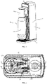
FIG. 1 is a perspective view of the present Patent. -
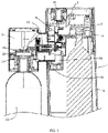
FIG. 2 is a sectional view of the present Patent. -
FIG. 3 is a view A-A ofFIG. 2 . -
FIG. 4 is a view B-B ofFIG. 2 . -
FIG. 5 is a first exploded perspective view of the present Patent. -
FIG. 6 is a second exploded perspective view of the present Patent. -
FIG. 7 is a third exploded perspective view of the present Patent. -
FIG. 8 is a fourth exploded perspective view of the present Patent. -
FIG. 9 is a partial perspective view of an auxiliary unit according to the present Patent. -
FIG. 10 is a perspective view of a support main body according to the present Patent. -
FIG. 11 is a first cross-sectional view of a support main body according to the present Patent. -
FIG. 12 is a second cross-sectional view of a support main body according to the present Patent. - The present Patent will be further described with reference to the attached drawings.
- As shown in
FIG. 1, FIG. 2 andFIG. 3 , a soda maker having convenient gas intake and discharge comprises amain unit 1 and anauxiliary unit 2. Themain unit 1 comprises ahousing 3, a base 4, a carbon dioxide cylinder provided within the housing, a gas intakemain body 5 provided at the top of the carbon dioxide cylinder, agas intake support 6, a gasintake connecting rod 7, and a locking engagement member 8. The gasintake connecting rod 7 is pivoted with the gas intakemain body 5. The locking engagement member 8 is pivoted with thegas intake support 6. The locking engagement member 8 is engaged with the gasintake connecting rod 7. Theauxiliary unit 2 comprises anouter casing 9, an auxiliary unitmain body 10, awater bottle coupler 11, atapered ring 12, and asoda bottle 13. Thetapered ring 12 is provided between the auxiliary unitmain body 10 and thewater bottle coupler 11. The auxiliary unitmain body 10 and thewater bottle coupler 11 are fixedly connected together. The auxiliary unitmain body 10 is provided with agas discharge valve 14, aswitch valve 15, and asafety valve 16. Thegas discharge valve 14, theswitch valve 15, and thesafety valve 16 are communicated with acavity 10A on the auxiliary unitmain body 10. Theouter casing 9 is connected with thehousing 3. The gas intakemain body 5 is communicated with agas intake assembly 17 on the auxiliary unitmain body 10. Agas rod 18 connected with thegas intake assembly 17 extends into thesoda bottle 13. - The
housing 3 is provided with aninstallation hole 31. - A connecting
part 91 is provided on theouter casing 9, twoparallel pivoting plates 92 are provided on the connecting part, and ahalf shaft 921 and apositioning protrusion 922 are provided on the pivoting plate. - The soda maker further comprises a
pivoting base 19 having a side opening and a top opening. - A
half shaft hole 191, an operation positioningblind hole 192 and a gas discharge positioningblind hole 193 are provided on the side wall plate of thepivoting base 19. Thepivoting base 19 is fixed within thehousing 3. The pivotingplate 92 passes through theinstallation hole 31. Thehalf shaft 921 is pivoted with thehalf shaft hole 191. During operation, thepositioning protrusion 922 is engaged with an operation positioningblind hole 192. An axis of the connectingpart 91 is parallel to a horizontal plane. Thegas discharge valve 14 is engaged with an end plate of the pivotingbase 19. Theswitch valve 15 is engaged with the locking engagement member 8. Thepositioning protrusion 922 is engaged with the gas discharge positioningblind hole 193. As shown inFIG. 11 , thegas discharge valve 14 comprises a gasdischarge valve body 141, a gasdischarge valve nut 142, a gasdischarge valve rod 143, a gasdischarge valve core 144 and apressure spring 145 which are provided on the auxiliary unit main body. The closed end of the gasdischarge valve body 141 is provided with a valve core base and is connected with thecavity 10A of the auxiliary unitmain body 10. The gasdischarge valve body 141 is provided with radial gas discharge holes 411. - The gas
discharge valve rod 143 comprises a drivingrod part 1431, a body part 1432, acircular disc 1433 surrounding the body part and astopper 1434 at the suspended end of the driving rod part. - The
gas discharge nut 142 comprises acavity part 1421, an internal thread part and a guide hole provided on the end plate. - The gas
discharge valve core 144 is provided at the end of the body part 1432. The body part 1432 is in sliding fit with the gasdischarge valve body 141. Thecircular disc 1433 is engaged with the end of the gasdischarge valve body 141. The drivingrod part 1431 extends through thepressure spring 145 and thegas discharge nut 142. Thecircular disc 1433 is in sliding fit with thecavity part 1421 of thegas discharge nut 142. Thepressure spring 145 is in sliding fit with thecircular disc 1433 and the end plate of thegas discharge nut 142. The drivingrod part 1431 is in sliding fit with the guide hole. The drivingrod part 1431 is embedded with a clampinggroove 194 on the end plate of the pivotingbase 19. Thestopper 1434 is engaged with the end plate of thepivoting base 1434. - During operation, the gas
discharge valve core 144 is embedded with the gas guide hole on the valve core base. Thepressure spring 145 is in an automatic state. - When discharging gas, the gas
discharge valve core 144 is separated from the gas guide hole on the valve core base, and thepressure spring 145 is in a compressed state. - The operation positioning
blind hole 192 and the gas discharge positioningblind hole 193 are communicated through an arc-shaped guide groove. - The connecting
part 91 is located in theinstallation hole 31, and there is a gap between the connectingpart 91 and theinstallation hole 31. - The
switch valve 15 comprises aswitch valve body 151 provided on the auxiliary unitmain body 10, a switchvalve core base 152 provided in the switch valve body, aswitch valve rod 153, avalve core 154, apressure spring 155, a switch nut 156 and a safetygas discharge device 157 communicated with the switch valve body. - The
switch valve rod 153 comprises a head part and a rod part, and the switch nut 156 comprises a cavity part, an external thread part and a valve rod hole. - The
valve core 154 is provided on the head of theswitch valve rod 153. Thevalve core 154 is engaged with the gas hole on the switchvalve core base 152. The head of the switchvalve core base 152 is in sliding fit with the inner cavity of theswitch valve body 151. Thepressure spring 155 is sleeved on the valve rod with one end engaged with the head of theswitch valve rod 153 and the other end engaged with the end plate of the cavity part of the switch nut 156. Theswitch valve rod 153 extends out of the switch nut 156 through the valve rod hole. Theswitch valve rod 153 is engaged with the locking engagement member. - The safety
gas discharge device 157 comprises agas discharge cavity 1571, a safetyvalve core base 1572 provided at the bottom of the gas discharge cavity, apressure relief hole 1573, asafety valve core 1574, avalve rod 1575, a pressure spring and aplug 1576. - The
safety valve core 1574 is provided on the head of thevalve rod 1575. Thesafety valve core 1574 is engaged with the safetyvalve core base 1572. Theplug 1576 is screwed with the internal thread part at the upper part of thegas discharge cavity 1571. The pressure spring is engaged with the head of thevalve rod 1575 and the internal counterbore on theplug 1576. - According to the present Patent, during operation, in the state shown in
FIGS. 1 and3 , the button 1A on themain unit 1 is pressed down, the gasintake connecting rod 7 rotates, the gasintake connecting rod 7 is locked with the locking engagement member 8, and theswitch valve rod 153 of theswitch valve 15 abuts against the lower end of the locking engagement member 8. The gas in the carbon dioxide cylinder extends into thesoda bottle 13 through the gas intakemain body 5, thegas intake assembly 17 on the auxiliary unitmain body 10 and thegas rod 18. - When the set pressure is reached in the
soda bottle 13, theswitch valve rod 153 of theswitch valve 15 moves and acts on the lower end of the locking engagement member 8. The locking engagement member 8 is separated from the gasintake connecting rod 7. The gasintake connecting rod 7 is reset, thus cutting off the gas path. - In the state shown in
FIG. 1 andFIG. 3 , theauxiliary unit 2 rotates clockwise, and the gasdischarge valve rod 143 is stationary relative to themain unit 1. The gasdischarge valve rod 143 compresses thepressure spring 145, and the gasdischarge valve core 144 leaves the valve core base and discharges gas. Then thesoda bottle 13 is removed for drinking. Theauxiliary unit 2 is reset, and the gasdischarge valve core 144 is attached to the valve core base. - The above is only the preferred embodiment of the present Patent. It should be pointed out that several improvements and modifications can be made without departing from the principle of the present Patent for those skilled in the art, which is also regarded as the scope of protection of the present Patent.
Claims (6)
- A soda maker having convenient gas intake and discharge, which comprises a main unit and an auxiliary unit, wherein the main unit comprises a housing, a base, a carbon dioxide cylinder provided within the housing, a gas intake main body provided at the top of the carbon dioxide cylinder, a gas intake support, a gas intake connecting rod, and a locking engagement member, the gas intake connecting rod is pivoted with the gas intake main body, the locking engagement member is pivoted with the gas intake support, the locking engagement member is engaged with the gas intake connecting rod; the auxiliary unit comprises an outer casing, an auxiliary unit main body, a water bottle coupler, a tapered ring, and a soda bottle, the auxiliary unit main body is provided with a gas discharge valve and a switch valve, the outer casing is connected with the housing, the gas intake main body is communicated with a gas intake assembly on the auxiliary unit main body, and a gas rod connected with the gas intake assembly extends into the soda bottle; wherein the housing is provided with an installation hole;a connecting part is provided on the outer casing, two parallel pivoting plates are provided on the connecting part, and a half shaft and a positioning protrusion are provided on the pivoting plate;the soda maker further comprises a pivoting base having a side opening and a top opening;a half shaft hole, an operation positioning blind hole and a gas discharge positioning blind hole are provided on the side wall plate of the pivoting base;the pivoting base is fixed within the housing, the pivoting plate passes through the installation hole, the half shaft is pivoted with the half shaft hole, during operation, the positioning protrusion is engaged with an operation positioning blind hole, an axis of the connecting part is parallel to a horizontal plane, the gas discharge valve is engaged with an end plate of the pivoting base, the switch valve is engaged with the locking engagement member, and the positioning protrusion is engaged with the gas discharge positioning blind hole.
- The soda maker having convenient gas intake and discharge according to claim 1, wherein the gas discharge valve comprises a gas discharge valve body, a gas discharge valve nut, a gas discharge valve rod, a gas discharge valve core and a pressure spring which are provided on the auxiliary unit main body, the closed end of the gas discharge valve body is provided with a valve core base and is connected with the cavity of the auxiliary unit main body, and the gas discharge valve body is provided with radial gas discharge holes;the gas discharge valve rod comprises a driving rod part, a body part, a circular disc surrounding the body part and a stopper at the suspended end of the driving rod part;the gas discharge nut comprises a cavity part, an internal thread part and a guide hole provided on the end plate;the gas discharge valve core is provided at the end of the body part, the body part is in sliding fit with the gas discharge valve body, the circular disc is engaged with the end of the gas discharge valve body, the driving rod part extends through the pressure spring and the gas discharge nut, the circular disc is in sliding fit with the cavity part of the gas discharge nut, the pressure spring is in sliding fit with the circular disc and the end plate of the gas discharge nut, the driving rod part is in sliding fit with the guide hole; the driving rod part is embedded with a clamping groove on the end plate of the pivoting base, and the stopper is engaged with the end plate of the pivoting base;during operation, the gas discharge valve core is embedded with the gas guide hole on the valve core base, the pressure spring is in an automatic state;when discharging gas, the gas discharge valve core is separated from the gas guide hole on the valve core base, and the pressure spring is in a compressed state.
- The soda maker having convenient gas intake and discharge according to claim 1, wherein the operation positioning blind hole and the gas discharge positioning blind hole are communicated through an arc-shaped guide groove.
- The soda maker having convenient gas intake and discharge according to claim 1, wherein the connecting part is located in the installation hole, and there is a gap between the connecting part and the installation hole.
- The soda maker having convenient gas intake and discharge according to claim 1, wherein the switch valve comprises a switch valve body provided on the auxiliary unit main body, a switch valve core base provided in the switch valve body, a switch valve rod, a valve core, a pressure spring, a switch nut and a safety gas discharge device communicated with the switch valve body;the switch valve rod comprises a head part and a rod part, and the switch nut comprises a cavity part, an external thread part and a valve rod hole;the valve core is provided on the head of the switch valve rod, the valve core is engaged with the gas hole on the switch valve core base, the head is in sliding fit with the inner cavity of the switch valve body, the pressure spring is sleeved on the valve rod with one end engaged with the head of the switch valve rod and the other end engaged with the end plate of the cavity part of the switch nut, the switch valve rod extends out of the switch nut through the valve rod hole, and the switch valve rod is engaged with the locking engagement member.
- The soda maker having convenient gas intake and discharge according to claim 5, wherein the safety gas discharge device comprises a gas discharge cavity, a safety valve core base provided at the bottom of the gas discharge cavity, a pressure relief hole, a safety valve core, a valve rod, a pressure spring and a plug;
the safety valve core is provided on the head of the valve rod, the safety valve core is engaged with the safety valve core base, the plug is screwed with the internal thread part at the upper part of the gas discharge cavity, and the pressure spring is engaged with the head of the valve rod and the internal counterbore on the plug.
Applications Claiming Priority (2)
| Application Number | Priority Date | Filing Date | Title |
|---|---|---|---|
| CN201921441761.5U CN211185739U (en) | 2019-08-30 | 2019-08-30 | Soda machine convenient for air intake and exhaust |
| PCT/CN2020/090845 WO2021036358A1 (en) | 2019-08-30 | 2020-05-18 | Soda maker having convenient gas intake and discharge |
Publications (4)
| Publication Number | Publication Date |
|---|---|
| EP4023117A1 true EP4023117A1 (en) | 2022-07-06 |
| EP4023117A4 EP4023117A4 (en) | 2023-09-06 |
| EP4023117C0 EP4023117C0 (en) | 2026-01-07 |
| EP4023117B1 EP4023117B1 (en) | 2026-01-07 |
Family
ID=71858310
Family Applications (1)
| Application Number | Title | Priority Date | Filing Date |
|---|---|---|---|
| EP20859261.8A Active EP4023117B1 (en) | 2019-08-30 | 2020-05-18 | Soda maker having convenient gas intake and discharge |
Country Status (6)
| Country | Link |
|---|---|
| US (1) | US20220218003A1 (en) |
| EP (1) | EP4023117B1 (en) |
| JP (1) | JP7489159B2 (en) |
| KR (1) | KR200497018Y1 (en) |
| CN (1) | CN211185739U (en) |
| WO (1) | WO2021036358A1 (en) |
Families Citing this family (7)
| Publication number | Priority date | Publication date | Assignee | Title |
|---|---|---|---|---|
| ES3070097T3 (en) * | 2020-12-23 | 2026-06-12 | Sodapop Gmbh | Receiving device for receiving a bottle on a carbonation machine, carbonation machine, and method for using a carbonation machine |
| CN113679246A (en) * | 2021-08-14 | 2021-11-23 | 深圳市礼家电器科技有限公司 | Bubble water machine with automatic exhaust valve |
| CN113974433B (en) * | 2021-11-17 | 2025-02-11 | 江门市伊科迈特电子科技有限公司 | A bubble water machine with automatic gas filling and residual quantity detection functions and a method of using the same |
| CN115804525B (en) * | 2022-12-08 | 2023-12-01 | 佛山市芯耀环保科技有限公司 | Pneumatic spring machine capable of automatically producing soda water |
| CN220256288U (en) * | 2023-08-21 | 2023-12-29 | 江门市伊科迈特电子科技有限公司 | Soda water machine with false touch switch |
| CN223473552U (en) * | 2024-12-04 | 2025-10-28 | 江门市伊科迈特电子科技有限公司 | Bubble water machine with low pressure keeps function |
| CN121828535B (en) * | 2026-03-16 | 2026-06-09 | 厦门微能电子科技有限公司 | Self-adaptation angle and self-bleeding's combination discharge valve |
Family Cites Families (12)
| Publication number | Priority date | Publication date | Assignee | Title |
|---|---|---|---|---|
| US4548828A (en) * | 1982-09-13 | 1985-10-22 | Meyers Louis B | Method for making carbonated beverages |
| US8888073B2 (en) * | 2011-10-11 | 2014-11-18 | Conair Corporation | Carbonated beverage appliance |
| CN202262390U (en) | 2011-10-18 | 2012-06-06 | 宋宁 | Portable aerated water machine with small replaceable steel cylinder |
| CN203801663U (en) | 2014-01-21 | 2014-09-03 | 宋宁 | Aerated water machine of aerated water bottle self-sealing and carbon dioxide gas leakage protective device |
| CN105078252B (en) * | 2015-09-14 | 2017-10-10 | 深圳市宝威家用电器有限公司 | A kind of Household soda water machine |
| CN205267847U (en) * | 2015-09-14 | 2016-06-01 | 深圳市宝威家用电器有限公司 | Domestic aerated water machine |
| CN205514109U (en) * | 2016-01-29 | 2016-08-31 | 宋宁 | A kind of soda machine that automatically closes the air outlet valve |
| GB201619695D0 (en) * | 2016-11-22 | 2017-01-04 | Hodges & Drake Design Ltd | Beverage flavouring apparatus |
| KR102062175B1 (en) | 2018-10-08 | 2020-01-02 | 백기현 | One-way valve for packages of fermentation food |
| CN209863391U (en) * | 2019-02-19 | 2019-12-31 | 关进业 | Soda machine with dustproof cover for seed machine |
| CN210810568U (en) * | 2019-04-19 | 2020-06-23 | 关进业 | Pneumatic system of aerated water machine integrating air intake, driving and pressure relief exhaust |
| CN210520786U (en) * | 2019-05-20 | 2020-05-15 | 关进业 | Soda machine with sub-machine locking |
-
2019
- 2019-08-30 CN CN201921441761.5U patent/CN211185739U/en active Active
-
2020
- 2020-05-18 US US17/595,647 patent/US20220218003A1/en active Pending
- 2020-05-18 EP EP20859261.8A patent/EP4023117B1/en active Active
- 2020-05-18 KR KR2020217000071U patent/KR200497018Y1/en active Active
- 2020-05-18 JP JP2021568179A patent/JP7489159B2/en active Active
- 2020-05-18 WO PCT/CN2020/090845 patent/WO2021036358A1/en not_active Ceased
Also Published As
| Publication number | Publication date |
|---|---|
| EP4023117A4 (en) | 2023-09-06 |
| US20220218003A1 (en) | 2022-07-14 |
| WO2021036358A1 (en) | 2021-03-04 |
| EP4023117C0 (en) | 2026-01-07 |
| CN211185739U (en) | 2020-08-07 |
| JP7489159B2 (en) | 2024-05-23 |
| JP2023529244A (en) | 2023-07-10 |
| KR200497018Y1 (en) | 2023-07-03 |
| KR20210002767U (en) | 2021-12-10 |
| EP4023117B1 (en) | 2026-01-07 |
Similar Documents
| Publication | Publication Date | Title |
|---|---|---|
| EP4023117B1 (en) | Soda maker having convenient gas intake and discharge | |
| US4809951A (en) | Spring compressor for large coil springs | |
| CN110604469B (en) | Pressure cooker with one-key control function | |
| US20200332505A1 (en) | Adjustable shower head holder with self-locking structure | |
| CN110715063B (en) | Fire extinguisher valve | |
| CN109703871B (en) | Cosmetic packaging bottle | |
| CN107342181B (en) | Emergency stop button | |
| CN209858130U (en) | Pressure gauge | |
| CN220291005U (en) | Battery cover plate with explosion-proof valve and battery | |
| CN219176451U (en) | Sealing flap device fixed by spring self-locking | |
| CN221238449U (en) | Anti-theft anti-disassembly meter connector device for gas meter | |
| EP3929366A1 (en) | Drain valve switch having clutch structure, and drain valve | |
| US10174883B1 (en) | Gas regulator with a gas-amount display assembly | |
| CN217338244U (en) | A bubble bomb feeding structure and bubble water machine | |
| CN218377255U (en) | Internal pressure self-locking safety bolt | |
| CN217723241U (en) | Hand-operated coffee machine | |
| CN210144473U (en) | Electric pressure cooker with pressure anti-uncovering device | |
| CN109373009B (en) | Limit switch indicating device for ship ball valve | |
| JP6080453B2 (en) | Fire extinguisher gas injector | |
| CN210520794U (en) | Submachine with fast and slow exhaust function | |
| CN220041654U (en) | Emergency stop switch capable of being used for automatic assembly | |
| CN223238458U (en) | Container cap without thread structure and container thereof | |
| CN222492299U (en) | Hole digger incomplete ejector | |
| CN110576524B (en) | An electric drill auxiliary device suitable for wall drilling | |
| CN112483670B (en) | Explosion-proof valve core and water valve |
Legal Events
| Date | Code | Title | Description |
|---|---|---|---|
| STAA | Information on the status of an ep patent application or granted ep patent |
Free format text: STATUS: THE INTERNATIONAL PUBLICATION HAS BEEN MADE |
|
| PUAI | Public reference made under article 153(3) epc to a published international application that has entered the european phase |
Free format text: ORIGINAL CODE: 0009012 |
|
| STAA | Information on the status of an ep patent application or granted ep patent |
Free format text: STATUS: REQUEST FOR EXAMINATION WAS MADE |
|
| 17P | Request for examination filed |
Effective date: 20211130 |
|
| AK | Designated contracting states |
Kind code of ref document: A1 Designated state(s): AL AT BE BG CH CY CZ DE DK EE ES FI FR GB GR HR HU IE IS IT LI LT LU LV MC MK MT NL NO PL PT RO RS SE SI SK SM TR |
|
| DAV | Request for validation of the european patent (deleted) | ||
| DAX | Request for extension of the european patent (deleted) | ||
| A4 | Supplementary search report drawn up and despatched |
Effective date: 20230804 |
|
| RIC1 | Information provided on ipc code assigned before grant |
Ipc: A23L 2/54 20060101ALI20230731BHEP Ipc: B01F 23/2361 20220101ALI20230731BHEP Ipc: A47J 31/46 20060101ALI20230731BHEP Ipc: A47J 31/44 20060101ALI20230731BHEP Ipc: A47J 31/00 20060101AFI20230731BHEP |
|
| GRAP | Despatch of communication of intention to grant a patent |
Free format text: ORIGINAL CODE: EPIDOSNIGR1 |
|
| STAA | Information on the status of an ep patent application or granted ep patent |
Free format text: STATUS: GRANT OF PATENT IS INTENDED |
|
| RIC1 | Information provided on ipc code assigned before grant |
Ipc: A47J 31/00 20060101AFI20250718BHEP Ipc: A47J 31/44 20060101ALI20250718BHEP Ipc: A47J 31/46 20060101ALI20250718BHEP Ipc: B01F 23/2361 20220101ALI20250718BHEP Ipc: A23L 2/54 20060101ALI20250718BHEP |
|
| INTG | Intention to grant announced |
Effective date: 20250731 |
|
| GRAS | Grant fee paid |
Free format text: ORIGINAL CODE: EPIDOSNIGR3 |
|
| GRAA | (expected) grant |
Free format text: ORIGINAL CODE: 0009210 |
|
| STAA | Information on the status of an ep patent application or granted ep patent |
Free format text: STATUS: THE PATENT HAS BEEN GRANTED |
|
| AK | Designated contracting states |
Kind code of ref document: B1 Designated state(s): AL AT BE BG CH CY CZ DE DK EE ES FI FR GB GR HR HU IE IS IT LI LT LU LV MC MK MT NL NO PL PT RO RS SE SI SK SM TR |
|
| REG | Reference to a national code |
Ref country code: CH Ref legal event code: F10 Free format text: ST27 STATUS EVENT CODE: U-0-0-F10-F00 (AS PROVIDED BY THE NATIONAL OFFICE) Effective date: 20260107 Ref country code: GB Ref legal event code: FG4D |
|
| REG | Reference to a national code |
Ref country code: DE Ref legal event code: R096 Ref document number: 602020065305 Country of ref document: DE |
|
| REG | Reference to a national code |
Ref country code: IE Ref legal event code: FG4D |
|
| U01 | Request for unitary effect filed |
Effective date: 20260126 |
|
| U07 | Unitary effect registered |
Designated state(s): AT BE BG DE DK EE FI FR IT LT LU LV MT NL PT RO SE SI Effective date: 20260202 |
|
| REG | Reference to a national code |
Ref country code: CH Ref legal event code: W10 Free format text: ST27 STATUS EVENT CODE: U-0-0-W10-W00 (AS PROVIDED BY THE NATIONAL OFFICE) Effective date: 20260430 Ref country code: CH Ref legal event code: Y10 Free format text: ST27 STATUS EVENT CODE: U-0-0-Y10-Y00 (AS PROVIDED BY THE NATIONAL OFFICE) Effective date: 20260430 |
|
| RAP2 | Party data changed (patent owner data changed or rights of a patent transferred) |
Owner name: GUANGZHOU YIKE TRADING CO., LTD. |
|
| RIN2 | Information on inventor provided after grant (corrected) |
Inventor name: GUAN, JIN YE |
|
| U1K | Transfer of rights of the unitary patent after the registration of the unitary effect |
Owner name: GUANGZHOU YIKE TRADING CO., LTD.; CN |
|
| U20 | Renewal fee for the european patent with unitary effect paid |
Year of fee payment: 7 Effective date: 20260506 |
|
| PG25 | Lapsed in a contracting state [announced via postgrant information from national office to epo] |
Ref country code: RS Free format text: LAPSE BECAUSE OF FAILURE TO SUBMIT A TRANSLATION OF THE DESCRIPTION OR TO PAY THE FEE WITHIN THE PRESCRIBED TIME-LIMIT Effective date: 20260407 |
|
| PG25 | Lapsed in a contracting state [announced via postgrant information from national office to epo] |
Ref country code: ES Free format text: LAPSE BECAUSE OF FAILURE TO SUBMIT A TRANSLATION OF THE DESCRIPTION OR TO PAY THE FEE WITHIN THE PRESCRIBED TIME-LIMIT Effective date: 20260107 |
|
| PG25 | Lapsed in a contracting state [announced via postgrant information from national office to epo] |
Ref country code: PL Free format text: LAPSE BECAUSE OF FAILURE TO SUBMIT A TRANSLATION OF THE DESCRIPTION OR TO PAY THE FEE WITHIN THE PRESCRIBED TIME-LIMIT Effective date: 20260107 |
|
| PG25 | Lapsed in a contracting state [announced via postgrant information from national office to epo] |
Ref country code: GR Free format text: LAPSE BECAUSE OF FAILURE TO SUBMIT A TRANSLATION OF THE DESCRIPTION OR TO PAY THE FEE WITHIN THE PRESCRIBED TIME-LIMIT Effective date: 20260408 |
|
| PG25 | Lapsed in a contracting state [announced via postgrant information from national office to epo] |
Ref country code: NO Free format text: LAPSE BECAUSE OF FAILURE TO SUBMIT A TRANSLATION OF THE DESCRIPTION OR TO PAY THE FEE WITHIN THE PRESCRIBED TIME-LIMIT Effective date: 20260407 |
|
| PG25 | Lapsed in a contracting state [announced via postgrant information from national office to epo] |
Ref country code: HR Free format text: LAPSE BECAUSE OF FAILURE TO SUBMIT A TRANSLATION OF THE DESCRIPTION OR TO PAY THE FEE WITHIN THE PRESCRIBED TIME-LIMIT Effective date: 20260107 |
|
| PG25 | Lapsed in a contracting state [announced via postgrant information from national office to epo] |
Ref country code: IS Free format text: LAPSE BECAUSE OF FAILURE TO SUBMIT A TRANSLATION OF THE DESCRIPTION OR TO PAY THE FEE WITHIN THE PRESCRIBED TIME-LIMIT Effective date: 20260507 |