EP4023073A1 - Ice cream freezer - Google Patents
Ice cream freezer Download PDFInfo
- Publication number
- EP4023073A1 EP4023073A1 EP21210183.6A EP21210183A EP4023073A1 EP 4023073 A1 EP4023073 A1 EP 4023073A1 EP 21210183 A EP21210183 A EP 21210183A EP 4023073 A1 EP4023073 A1 EP 4023073A1
- Authority
- EP
- European Patent Office
- Prior art keywords
- ice cream
- cylinder body
- outlet
- inlet
- mass
- Prior art date
- Legal status (The legal status is an assumption and is not a legal conclusion. Google has not performed a legal analysis and makes no representation as to the accuracy of the status listed.)
- Granted
Links
Images



Classifications
-
- A—HUMAN NECESSITIES
- A23—FOODS OR FOODSTUFFS; TREATMENT THEREOF, NOT COVERED BY OTHER CLASSES
- A23G—COCOA; COCOA PRODUCTS, e.g. CHOCOLATE; SUBSTITUTES FOR COCOA OR COCOA PRODUCTS; CONFECTIONERY; CHEWING GUM; ICE-CREAM; PREPARATION THEREOF
- A23G9/00—Frozen sweets, e.g. ice confectionery, ice-cream; Mixtures therefor
- A23G9/04—Production of frozen sweets, e.g. ice-cream
- A23G9/14—Continuous production
- A23G9/16—Continuous production the products being within a cooled chamber, e.g. drum
-
- A—HUMAN NECESSITIES
- A23—FOODS OR FOODSTUFFS; TREATMENT THEREOF, NOT COVERED BY OTHER CLASSES
- A23G—COCOA; COCOA PRODUCTS, e.g. CHOCOLATE; SUBSTITUTES FOR COCOA OR COCOA PRODUCTS; CONFECTIONERY; CHEWING GUM; ICE-CREAM; PREPARATION THEREOF
- A23G9/00—Frozen sweets, e.g. ice confectionery, ice-cream; Mixtures therefor
- A23G9/04—Production of frozen sweets, e.g. ice-cream
- A23G9/14—Continuous production
- A23G9/16—Continuous production the products being within a cooled chamber, e.g. drum
- A23G9/166—Feeding arrangements
-
- A—HUMAN NECESSITIES
- A23—FOODS OR FOODSTUFFS; TREATMENT THEREOF, NOT COVERED BY OTHER CLASSES
- A23G—COCOA; COCOA PRODUCTS, e.g. CHOCOLATE; SUBSTITUTES FOR COCOA OR COCOA PRODUCTS; CONFECTIONERY; CHEWING GUM; ICE-CREAM; PREPARATION THEREOF
- A23G9/00—Frozen sweets, e.g. ice confectionery, ice-cream; Mixtures therefor
- A23G9/04—Production of frozen sweets, e.g. ice-cream
- A23G9/22—Details, component parts or accessories of apparatus insofar as not peculiar to a single one of the preceding groups
-
- A—HUMAN NECESSITIES
- A23—FOODS OR FOODSTUFFS; TREATMENT THEREOF, NOT COVERED BY OTHER CLASSES
- A23G—COCOA; COCOA PRODUCTS, e.g. CHOCOLATE; SUBSTITUTES FOR COCOA OR COCOA PRODUCTS; CONFECTIONERY; CHEWING GUM; ICE-CREAM; PREPARATION THEREOF
- A23G9/00—Frozen sweets, e.g. ice confectionery, ice-cream; Mixtures therefor
- A23G9/04—Production of frozen sweets, e.g. ice-cream
- A23G9/22—Details, component parts or accessories of apparatus insofar as not peculiar to a single one of the preceding groups
- A23G9/222—Freezing drums
-
- A—HUMAN NECESSITIES
- A23—FOODS OR FOODSTUFFS; TREATMENT THEREOF, NOT COVERED BY OTHER CLASSES
- A23G—COCOA; COCOA PRODUCTS, e.g. CHOCOLATE; SUBSTITUTES FOR COCOA OR COCOA PRODUCTS; CONFECTIONERY; CHEWING GUM; ICE-CREAM; PREPARATION THEREOF
- A23G9/00—Frozen sweets, e.g. ice confectionery, ice-cream; Mixtures therefor
- A23G9/04—Production of frozen sweets, e.g. ice-cream
- A23G9/22—Details, component parts or accessories of apparatus insofar as not peculiar to a single one of the preceding groups
- A23G9/224—Agitators or scrapers
-
- A—HUMAN NECESSITIES
- A23—FOODS OR FOODSTUFFS; TREATMENT THEREOF, NOT COVERED BY OTHER CLASSES
- A23G—COCOA; COCOA PRODUCTS, e.g. CHOCOLATE; SUBSTITUTES FOR COCOA OR COCOA PRODUCTS; CONFECTIONERY; CHEWING GUM; ICE-CREAM; PREPARATION THEREOF
- A23G9/00—Frozen sweets, e.g. ice confectionery, ice-cream; Mixtures therefor
- A23G9/04—Production of frozen sweets, e.g. ice-cream
- A23G9/22—Details, component parts or accessories of apparatus insofar as not peculiar to a single one of the preceding groups
- A23G9/26—Details, component parts or accessories of apparatus insofar as not peculiar to a single one of the preceding groups for producing frozen sweets on sticks
-
- A—HUMAN NECESSITIES
- A23—FOODS OR FOODSTUFFS; TREATMENT THEREOF, NOT COVERED BY OTHER CLASSES
- A23G—COCOA; COCOA PRODUCTS, e.g. CHOCOLATE; SUBSTITUTES FOR COCOA OR COCOA PRODUCTS; CONFECTIONERY; CHEWING GUM; ICE-CREAM; PREPARATION THEREOF
- A23G9/00—Frozen sweets, e.g. ice confectionery, ice-cream; Mixtures therefor
- A23G9/04—Production of frozen sweets, e.g. ice-cream
- A23G9/22—Details, component parts or accessories of apparatus insofar as not peculiar to a single one of the preceding groups
- A23G9/28—Details, component parts or accessories of apparatus insofar as not peculiar to a single one of the preceding groups for portioning or dispensing
- A23G9/281—Details, component parts or accessories of apparatus insofar as not peculiar to a single one of the preceding groups for portioning or dispensing at the discharge end of freezing chambers
Definitions
- the invention relates to an ice cream freezer that has an elongated housing in which a dasher is arranged.
- the dasher has a hollow cylinder body for agitating and mixing ice cream mixture.
- a scraper blade is arranged along the periphery of the cylinder body, an inlet for the ice cream mixture is located before the scraper blade and an outlet for the ice cream mixture is located after the scraper blade, for allowing ice cream mixture to enter respectively leave the inside of the cylinder body.
- the invention is also related to a system and a method for producing ice cream by using this type of ice cream freezer.
- ice cream products Today a number of food handling apparatuses are used in the food processing industry to produce ice cream products, which include dairy based ice cream products as well as water-based frozen snack such as ice pops. Frozen custard, frozen yogurt, sorbet, gelato and frozen dairy dessert are some product names that are used to distinguish different varieties and styles of ice cream products.
- an ice cream mixture that shall be processed into the ice cream product is prepared.
- the mixture is often pumped through a continuous freezer which has two major functions. The first function is to whip a controlled amount of air into the mixture and the second function is to freeze a significant part of the water in the mixture into a large number of small ice crystals.
- the continuous freezer typically has the form of a jacketed, cylinder-shaped housing in which knives, a dasher and sometimes also a beater are arranged to rotate.
- the ice cream mixture is metered into the housing, for example by using a gear pump.
- a constant airflow is fed into the housing and whipped into the mixture by the rotating dasher that is located within the jacketed housing.
- the dasher then effectively works as both an agitator and mixer for the ice cream mixture.
- a refrigerant passing through the jacket surrounding the housing freezes the ice cream mixture that is feed into the freezer, such that ice crystals are formed in the ice cream mixture.
- the ice cream mixture is thereafter used to form ice cream products.
- the knives also referred to as scraper blades, are arranged on the rotating dasher so that frozen mixture on the inside housing wall is continuously scraped off by the knifes.
- the dasher keeps the product agitated inside the dasher.
- a controlled amount of air is, either separately or along with the ice cream mixture, fed into the freezer.
- the rotation of the dasher ensures that the air is evenly mixed into the mixture, thereby forming a homogeneous ice cream mixture. If a beater is used for the freezer, the beater causes the mixture to be subjected to a whipping action that intensifies the mixing of the air into the ice cream mixture.
- the mixing of air into the ice cream mixture increases its volume. 0,8 to 1 liter of air is commonly introduced for each liter of ice cream mixture.
- the temperature of the mixture when leaving the freezer is often from -8 °C to -3 °C depending on the type of ice cream product, where 30% to 55% of the water in the mixture may be frozen into ice crystals depending on the composition of the mixture.
- a pump is often used to drive the ice cream mixture forward from the continues freezer, for example to an ingredient feeder, an ice cream forming apparatus or to a filling machine.
- a pump may alternatively or additionally be arranged upstream the freezer for feeding the mixture into the freezer. As the temperature of the mixture gradually decreases when it passes through the freezer, its viscosity increases and more energy is required to convey the mixture through the freezer.
- an ice cream freezer that comprises an elongated housing having a jacket and an interior space, and a dasher comprising a hollow cylinder body arranged in the interior space for rotating in a rotational direction about a central axis of the cylinder body to agitate and mix ice cream mixture that is fed through the interior space.
- the cylinder body comprises a scraper blade arranged along the periphery of the cylinder body, an inlet that is, as seen in the rotational direction, located before the scraper blade for allowing ice cream mixture to enter an inside of the cylinder body, and an outlet that is, as seen in the rotational direction, located after the scraper blade for allowing ice cream mixture to leave the inside of the cylinder body.
- the inlet comprises a lead surface that has a lead angle of at least 3° for pushing the ice cream mixture in the axial direction of the cylinder body.
- a cylinder body inlet that has an angled lead surface is advantageous in that it assists in continuously pushing the ice cream forward.
- the direction by which the ice cream mixture is pushed is from the ice cream mixture inlet of the housing to the ice cream mixture outlet of the housing.
- the dasher also acts a pumping unit for the ice cream mixture. This assists in ensuring that there is a sufficient discharge out from the freezer.
- the angled lead surface also contributes to saving the total amount of energy needed for feeding ice cream mixture through the ice cream freezer.
- an ice cream production system that comprises an ice cream freezer for producing ice cream mass, an ice cream forming apparatus arranged to shape the ice cream mass into individual pieces of ice cream mass, a freezing apparatus arranged to receive the individual pieces of ice cream mass and reduce their temperature, a packaging machine arranged to wrap package material around each individual piece of ice cream mass, where the ice cream freezer is an ice cream freezer according to the first aspect.
- a method for producing ice cream comprising producing ice cream mass, shaping the ice cream mass into individual pieces of ice cream mass, reducing the temperature of the individual pieces of ice cream mass, wrapping package material around each individual piece of ice cream mass, where the producing of ice cream mass comprises using an ice cream freezer according to the first aspect.
- the ice cream freezer 1 has an elongated housing 2 which has a jacket 3 and a cylindrically shaped interior space 4.
- a dasher 30 is arranged in the interior space 4 and has a hollow cylinder body 31 that is mounted to rotate in a rotational direction R about a central axis A1 of the cylinder body 31.
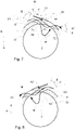
- the cylinder body 31 has a peripheral surface 34 and an interior surface 33, see Fig. 7 .
- the distance between these surfaces 34, 33 defines the thickness t of the hollow cylinder body 31.
- the thickness may, for example, be 5 mm to 15 mm.
- the housing 2 has first inlet 11 and a first outlet 12 that are arranged for feeding ice cream mixture M through the interior space 4.
- the housing 2 has a second inlet 21 and a second outlet 22 that are arranged for feeding a cooling fluid CF, i.e. a refrigerant, through the jacket 3 to thereby cool ice cream mixture M that is fed through the interior space 4.
- a cooling fluid CF i.e. a refrigerant
- a motor (not shown) is connected to an axis 15 of the dasher 30 for rotating the dasher 30.
- the cylinder body 31 also rotates in the rotational direction R.
- ice cream mixture M that is fed through the interior space 4 is agitated and mixed.
- the cylinder body 31 has a scraper blade 50 that is mounted along the periphery of the cylinder body 31 to enable the blade 50 to scrape off ice cream mixture from the inner wall 5 of the housing 2.
- the scraper blade 50 is mounted with its tip foremost in the rotational direction R.
- the cylinder body 31 has an inlet 60 that is, as seen in the rotational direction R, located before the scraper blade 50. This allows ice cream mixture M to be pushed into an inside 32 of the hollow cylinder body 31 when it is rotated.
- the cylinder body 31 has an outlet 62 that is, as seen in the rotational direction R, located after the scraper blade 50. This provides for letting out ice cream mixture M from the inside 32 of the cylinder body 31 when it is rotated. In this way ice cream mixture M may be continuously fed into and out from the inside 32 of the cylinder body 31.
- the inlet 60 ha a lead surface 67 that has a lead angle ⁇ of at least 3°.
- the lead surface 67 pushes the ice cream mixture M in the axial direction D of the cylinder body 31. This effectively pushes the ice cream mixture M in the direction from the first inlet 11 to the first outlet 12, which are arranged for feeding ice cream mixture M through the interior space 4 of the housing 2.
- the lead angle ⁇ may be at least 5°, at least 8°, at least 15° or even at least 30°. When the lead angle ⁇ is at least 3°, 5°, 8°, or 15°, then the lead angle ⁇ may be less than 25°, i.e. have an upper limit of 25°.
- the lead angle ⁇ references a line perpendicular to the axis A1 of the cylinder body 31, and is the complement to the helix angle which references the axis A1 of the cylinder body 31.
- the lead surface 67 may be slightly concave or may be slightly convex, in which case the lead angle ⁇ is calculated as the mean lead angle for the curvature forming the lead surface 67.
- the inlet 60 may have a surface 61 that is opposite the lead surface 67 and inclined by an angle that is same as the lead angle ⁇ of the lead surface 67.
- the inlet 60 and the outlet 62 may form a hole 91 in the cylinder body 31, and the scraper blade 50 may be arranged above the hole 91 to separate the hole 91 into the inlet 60 and outlet 62.
- This is advantageous form a manufacturing perspective, allowing both the inlet 60 and outlet 62 to be created in one operation, having the scraper blade 50 separating the inlet 60 from the outlet 62.
- the hole 91 is also advantageous in that ice cream mixture more easily flows in to and out from the inside 32 of the cylinder body 31 via the inlet 60 and outlet 62.
- the lead surface 67 may extend from the inlet 60 to the outlet 62. This is advantageous in that the outlet 62 then also comprises the lead surface 67, further enhancing the pumping effect of the dasher 30.
- the outlet 62 may also have a surface that is opposite the lead surface 67 and inclined by an angle that is same as the lead angle ⁇ of the lead surface 67.
- the inlet 60 may comprise an inlet surface 64 that is top chamfered or top beveled by an angle ⁇ of at least 10°.
- the inlet surface 64 is chamfered.
- the angle ⁇ of the chamfer (inlet chamfer) 64 is measured relative the radial direction of the cylinder body 31 at the location 71 where the chamfer 64 starts on the peripheral surface 34 of the cylinder body 31, as indicated in Fig. 7 .
- the chamfer 64 extends inwards in a direction towards the interior surface 33 of the hollow cylinder body 31.
- the chamfer 64 may have an angle ⁇ of at least 20°, at least 40°, or at least 60°.
- the inlet surface 64 may be top chamfered over at least 30% of the thickness t of the cylinder body 31.
- the inlet surface 64 may be top chamfered over at least 30%, least 40%, least 50%, least 60% or least 80% of the thickness t of the cylinder body 31. It may even be top chamfered over 100% of the thickness t of the cylinder body 31, in which case it is beveled.
- Having a chamfered inlet surface 64 is advantageous in that ice cream mass is more easily pushed to the inside 32 of the cylinder body 31, requiring less energy to rotate the dasher 30. Additionally, the mixing efficiency of the dasher 30 is increased.
- the outlet 62 of the cylinder body 31 may comprise an outlet surface 65 that is top chamfered or top beveled by an angle ⁇ of at least 10°.
- the outlet surface 65 is chamfered.
- the angle ⁇ of the outlet chamfer 65 is measured relative the radial direction of the cylinder body 31 at the location 72 where the outlet chamfer 65 starts on the peripheral surface 34 of the cylinder body 31, as indicated in Fig. 7 .
- the outlet chamfer 65 extends inwards in a direction towards the interior surface 33 of the hollow cylinder body 31.
- the outlet chamfer 65 may have an angle ⁇ of at least 20°, at least 40°, or at least 60°.
- the outlet surface 65 may be top chamfered over at least 30% of the thickness t of the cylinder body 31.
- the outlet surface 65 may be top chamfered over at least 30%, least 40%, least 50%, least 60% or least 80% of the thickness t of the cylinder body 31. It may even be top chamfered over 100% of the thickness t of the cylinder body 31, in which case it is beveled.
- Having a chamfered outlet surface 65 is advantageous in that ice cream mass more easily flows out from the inside 32 of the cylinder body 31, requiring less energy to rotate the dasher 30. Additionally, the mixing efficiency of the dasher 30 is increased.
- the inlet chamfer 64 and the outlet chamfer 65 may be chamfered or beveled by the same chamfer or bevel angle. This is advantageous from a manufacturing perspective and also improves the flow of ice cream mixture into and out from the cylinder body 31.
- the cylinder body 31 may have a protrusion 63 that extends over the outlet 62.
- the scraper blade 50 may be attached to an end section 81 of the protrusion 63.
- the scraper blades attachment point is then located above the hole 91.
- the protrusion 63 may extend from the outlet surface 65 and separate the outlet 62 into two outlet surface sections 65, 66.
- the protrusion 63 may comprise an inner surface 82 that is directed towards a center C of the cylinder body 31. This inner surface 82 may inclined by an angle ⁇ of at least 10° relative a tangential direction T of the cylinder body 31.
- the tangential direction T is defined by the point 70 on the cylinder body 31 that is radially aligned with the end section 81 of the protrusion 63, as shown in Fig. 7 along axis A2.
- the hole 91 may be one of a sequence of similar holes 91, 92 that are arranged in the cylinder body 31.
- the holes 91, 92 extend in the axial direction D of the cylinder body 31 and are separated by ribs 93.
- the scraper blade 50 extends over the ribs 93.
- the ribs 93 have a respective outer surface 94 that is chamfered or beveled by at least 3 mm in the axial direction D of the cylinder body 31, forming a chamfer 69 in the rib 93.
- the chamfer 69 in the rib 93 is located where the scraper blade 50 extends over the rib 93.
- the chamfer 69 may extend over at least 75% of the width of the rib 93, or may even extend over the entire width of the rib 93.
- the width of the rib 93 extends in the axial direction D of the cylinder body 31.
- the width of the rib may, for example, be 10 mm to 20 mm.
- the chamfer 69 in the rib 93 provides for easier cleaning as well as for improved flow of ice cream mixture M, in particular out from the outlet 62.
- One or more of the ribs 91 may comprise the lead surface 67 of an inlet 60 of the cylinder body 31. Then the outer surfaces 94 of the ribs 91 are preferably chamfered or beveled on the side 61 of the respective rib 91 that that is opposite the lead surface 67 that is comprised in the rib 91.
- the cylinder body 31 may include ribs that have other forms and shapes.
- Another example of a dasher 130 is shown in Fig. 9 and 10 .
- the cylinder body 131 has different shapes of the holes 191, 192 and the ribs 193, where an angled lead surface 167 assists in pushing the ice cream mixture in the axial direction.
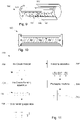
- ice cream production system 700 is illustrated.
- ice cream mass M can be produced by using an ice cream freezer 702.
- the ice cream freezer 702 is advantageously an ice cream freezer 1 as described above.
- the ice cream mass M may thereafter be formed in an ice cream forming apparatus 704 into individual pieces 705 of ice cream mass. This may be made in different ways, e.g. by using extrusion or moulding.
- a stick handling apparatus 706, which is optional, may place ice cream sticks in the individual pieces 705 of ice cream mass.
- the individual pieces 705 may be placed in a freezing apparatus 707, e.g. a freezing tunnel. Lastly, in a packaging machine 708, the individual pieces 705 can be wrapped in package material 710 such that ice cream products ready to be shipped are formed.
- the ice cream forming apparatus 704, the stick handling apparatus 706, the freezing apparatus 707 and the packaging machine 708 are typically commercially available apparatuses suitable for ice cream production.
- the method 800 comprises producing 802 ice cream mass, shaping 804 the ice cream mass M into individual pieces of ice cream mass, reducing 807 the temperature of the individual pieces of ice cream mass and wrapping 808 package material 710 around each individual piece of ice cream mass 705.
- the producing 802 of ice cream mass 304 comprises using an ice cream freezer 1 as described above.
- ice cream sticks are handled 806 by inserting the sticks into the individual pieces of ice cream mass.
Landscapes
- Engineering & Computer Science (AREA)
- Life Sciences & Earth Sciences (AREA)
- Chemical & Material Sciences (AREA)
- Food Science & Technology (AREA)
- Polymers & Plastics (AREA)
- Manufacturing & Machinery (AREA)
- Confectionery (AREA)
- Accessories For Mixers (AREA)
- Mixers Of The Rotary Stirring Type (AREA)
Abstract
Description
- The invention relates to an ice cream freezer that has an elongated housing in which a dasher is arranged. The dasher has a hollow cylinder body for agitating and mixing ice cream mixture. A scraper blade is arranged along the periphery of the cylinder body, an inlet for the ice cream mixture is located before the scraper blade and an outlet for the ice cream mixture is located after the scraper blade, for allowing ice cream mixture to enter respectively leave the inside of the cylinder body. The invention is also related to a system and a method for producing ice cream by using this type of ice cream freezer.
- Today a number of food handling apparatuses are used in the food processing industry to produce ice cream products, which include dairy based ice cream products as well as water-based frozen snack such as ice pops. Frozen custard, frozen yogurt, sorbet, gelato and frozen dairy dessert are some product names that are used to distinguish different varieties and styles of ice cream products.
- During large scale production of an ice cream product, an ice cream mixture that shall be processed into the ice cream product is prepared. The mixture is often pumped through a continuous freezer which has two major functions. The first function is to whip a controlled amount of air into the mixture and the second function is to freeze a significant part of the water in the mixture into a large number of small ice crystals.
- The continuous freezer typically has the form of a jacketed, cylinder-shaped housing in which knives, a dasher and sometimes also a beater are arranged to rotate. During production, the ice cream mixture is metered into the housing, for example by using a gear pump. At the same time, a constant airflow is fed into the housing and whipped into the mixture by the rotating dasher that is located within the jacketed housing. The dasher then effectively works as both an agitator and mixer for the ice cream mixture. A refrigerant passing through the jacket surrounding the housing freezes the ice cream mixture that is feed into the freezer, such that ice crystals are formed in the ice cream mixture. The ice cream mixture is thereafter used to form ice cream products.
- The knives, also referred to as scraper blades, are arranged on the rotating dasher so that frozen mixture on the inside housing wall is continuously scraped off by the knifes. The dasher keeps the product agitated inside the dasher. A controlled amount of air is, either separately or along with the ice cream mixture, fed into the freezer. The rotation of the dasher ensures that the air is evenly mixed into the mixture, thereby forming a homogeneous ice cream mixture. If a beater is used for the freezer, the beater causes the mixture to be subjected to a whipping action that intensifies the mixing of the air into the ice cream mixture.
- The mixing of air into the ice cream mixture increases its volume. 0,8 to 1 liter of air is commonly introduced for each liter of ice cream mixture. The temperature of the mixture when leaving the freezer is often from -8 °C to -3 °C depending on the type of ice cream product, where 30% to 55% of the water in the mixture may be frozen into ice crystals depending on the composition of the mixture.
- To convey the ice cream mixture through the freezer a pump is often used to drive the ice cream mixture forward from the continues freezer, for example to an ingredient feeder, an ice cream forming apparatus or to a filling machine. Depending on the configuration, a pump may alternatively or additionally be arranged upstream the freezer for feeding the mixture into the freezer. As the temperature of the mixture gradually decreases when it passes through the freezer, its viscosity increases and more energy is required to convey the mixture through the freezer.
- Examples of freezers for ice cream are found in patent documents
EP1178734B1 andUS4162127A . - Even though continuous ice cream freezers successfully freeze ice cream mixtures, there I still a limitation in respect of how low the temperature may be for the mixture passing through the freezer. In particular for low fat ice cream products such as sorbet and water ice the viscosity increases fast when lowering the temperature. The high viscosity of such products makes it challenging to provide sufficient pumping through the freezer, to ensure that sufficient discharge pressure to the discharge pump is provided. From another perspective, even though ice cream mixtures having a lower water content does not experience the same, rapid increase of viscosity, a relatively large amount of energy is still needed to convey the mixture through the freezer.
- It is an object of the invention to at least partly overcome one or more limitations of the prior art. In particular, it is an object to provide an ice cream freezer through which an ice cream mixture is more easily fed, for example to save energy and/or to ensure that there is a sufficient discharge out from the freezer.
- In a first aspect of the invention, this is achieved by an ice cream freezer that comprises an elongated housing having a jacket and an interior space, and a dasher comprising a hollow cylinder body arranged in the interior space for rotating in a rotational direction about a central axis of the cylinder body to agitate and mix ice cream mixture that is fed through the interior space. The cylinder body comprises a scraper blade arranged along the periphery of the cylinder body, an inlet that is, as seen in the rotational direction, located before the scraper blade for allowing ice cream mixture to enter an inside of the cylinder body, and an outlet that is, as seen in the rotational direction, located after the scraper blade for allowing ice cream mixture to leave the inside of the cylinder body. The inlet comprises a lead surface that has a lead angle of at least 3° for pushing the ice cream mixture in the axial direction of the cylinder body.
- Using a cylinder body inlet that has an angled lead surface is advantageous in that it assists in continuously pushing the ice cream forward. Obviously, the direction by which the ice cream mixture is pushed is from the ice cream mixture inlet of the housing to the ice cream mixture outlet of the housing. Thus, in addition to agitating and mixing, the dasher also acts a pumping unit for the ice cream mixture. This assists in ensuring that there is a sufficient discharge out from the freezer. In many cases, the angled lead surface also contributes to saving the total amount of energy needed for feeding ice cream mixture through the ice cream freezer.
- Other objectives, features, aspects and advantages of the ice cream freezer will appear from the following detailed description as well as from the drawings.
- In a second aspect of the invention, above objects are also achieved by an ice cream production system that comprises an ice cream freezer for producing ice cream mass, an ice cream forming apparatus arranged to shape the ice cream mass into individual pieces of ice cream mass, a freezing apparatus arranged to receive the individual pieces of ice cream mass and reduce their temperature, a packaging machine arranged to wrap package material around each individual piece of ice cream mass, where the ice cream freezer is an ice cream freezer according to the first aspect.
- In a third aspect of the invention, above objects are also achieved by a method for producing ice cream, the method comprising producing ice cream mass, shaping the ice cream mass into individual pieces of ice cream mass, reducing the temperature of the individual pieces of ice cream mass, wrapping package material around each individual piece of ice cream mass, where the producing of ice cream mass comprises using an ice cream freezer according to the first aspect.
- Embodiments of the invention will now be described, by way of example, with reference to the accompanying schematic drawings, where
-
Fig. 1 is a schematic view of an ice cream freezer, -
Fig. 2 is a perspective view of a dasher for the ice cream freezer shown inFig. 1 , -
Fig. 3 is a front view of the dasher shown inFig. 2 , -
Fig. 4 is a side view of the dasher shown inFig. 2 , -
Fig. 5 is a partial front view of the dasher shown inFig. 2 , -
Fig. 6 is a partial perspective view of the dasher shown inFig. 2 , -
Fig. 7 is a schematic, cross-sectional side view of the dasher shown inFig. 2 , -
Fig. 8 is a schematic, cross-sectional side view of the dasher shown inFig. 2 , corresponding to the view ofFig. 7 but seen from an opposite side, -
Fig. 9 is a perspective view of another embodiment of a dasher for the ice cream freezer shown inFig. 1 , -
Fig. 10 is a front view of the dasher shown inFig. 9 , -
Fig. 11 is a schematic view of an ice cream production system, and -
Fig. 12 is a flow chart of a method for producing ice cream. - With reference to
Fig. 1 to 4 , an ice cream freezer 1 is illustrated. The ice cream freezer 1 has anelongated housing 2 which has ajacket 3 and a cylindrically shapedinterior space 4. Adasher 30 is arranged in theinterior space 4 and has ahollow cylinder body 31 that is mounted to rotate in a rotational direction R about a central axis A1 of thecylinder body 31. Thecylinder body 31 has aperipheral surface 34 and aninterior surface 33, seeFig. 7 . The distance between thesesurfaces hollow cylinder body 31. The thickness may, for example, be 5 mm to 15 mm. Thehousing 2 hasfirst inlet 11 and afirst outlet 12 that are arranged for feeding ice cream mixture M through theinterior space 4. Thehousing 2 has asecond inlet 21 and asecond outlet 22 that are arranged for feeding a cooling fluid CF, i.e. a refrigerant, through thejacket 3 to thereby cool ice cream mixture M that is fed through theinterior space 4. The dasher and all its parts may be made of stainless steel. - A motor (not shown) is connected to an
axis 15 of thedasher 30 for rotating thedasher 30. When the dasher is rotated thecylinder body 31 also rotates in the rotational direction R. When this happens ice cream mixture M that is fed through theinterior space 4 is agitated and mixed. Thecylinder body 31 has ascraper blade 50 that is mounted along the periphery of thecylinder body 31 to enable theblade 50 to scrape off ice cream mixture from theinner wall 5 of thehousing 2. Thescraper blade 50 is mounted with its tip foremost in the rotational direction R. - With reference to
Fig. 5 and 6 , thecylinder body 31 has aninlet 60 that is, as seen in the rotational direction R, located before thescraper blade 50. This allows ice cream mixture M to be pushed into an inside 32 of thehollow cylinder body 31 when it is rotated. Thecylinder body 31 has anoutlet 62 that is, as seen in the rotational direction R, located after thescraper blade 50. This provides for letting out ice cream mixture M from the inside 32 of thecylinder body 31 when it is rotated. In this way ice cream mixture M may be continuously fed into and out from the inside 32 of thecylinder body 31. - The
inlet 60 ha alead surface 67 that has a lead angle θ of at least 3°. Thelead surface 67 pushes the ice cream mixture M in the axial direction D of thecylinder body 31. This effectively pushes the ice cream mixture M in the direction from thefirst inlet 11 to thefirst outlet 12, which are arranged for feeding ice cream mixture M through theinterior space 4 of thehousing 2. - The lead angle θ may be at least 5°, at least 8°, at least 15° or even at least 30°. When the lead angle θ is at least 3°, 5°, 8°, or 15°, then the lead angle θ may be less than 25°, i.e. have an upper limit of 25°. The lead angle θ references a line perpendicular to the axis A1 of the
cylinder body 31, and is the complement to the helix angle which references the axis A1 of thecylinder body 31. Thelead surface 67 may be slightly concave or may be slightly convex, in which case the lead angle θ is calculated as the mean lead angle for the curvature forming thelead surface 67. Theinlet 60 may have asurface 61 that is opposite thelead surface 67 and inclined by an angle that is same as the lead angle θ of thelead surface 67. - The
inlet 60 and theoutlet 62 may form ahole 91 in thecylinder body 31, and thescraper blade 50 may be arranged above thehole 91 to separate thehole 91 into theinlet 60 andoutlet 62. This is advantageous form a manufacturing perspective, allowing both theinlet 60 andoutlet 62 to be created in one operation, having thescraper blade 50 separating theinlet 60 from theoutlet 62. Thehole 91 is also advantageous in that ice cream mixture more easily flows in to and out from the inside 32 of thecylinder body 31 via theinlet 60 andoutlet 62. - The
lead surface 67 may extend from theinlet 60 to theoutlet 62. This is advantageous in that theoutlet 62 then also comprises thelead surface 67, further enhancing the pumping effect of thedasher 30. Theoutlet 62 may also have a surface that is opposite thelead surface 67 and inclined by an angle that is same as the lead angle θ of thelead surface 67. - With further reference to
Fig. 7 and 8 , theinlet 60 may comprise aninlet surface 64 that is top chamfered or top beveled by an angle β of at least 10°. In the illustrated example theinlet surface 64 is chamfered. The angle β of the chamfer (inlet chamfer) 64 is measured relative the radial direction of thecylinder body 31 at thelocation 71 where thechamfer 64 starts on theperipheral surface 34 of thecylinder body 31, as indicated inFig. 7 . Thechamfer 64 extends inwards in a direction towards theinterior surface 33 of thehollow cylinder body 31. Thechamfer 64 may have an angle β of at least 20°, at least 40°, or at least 60°. - The
inlet surface 64 may be top chamfered over at least 30% of the thickness t of thecylinder body 31. Theinlet surface 64 may be top chamfered over at least 30%, least 40%, least 50%, least 60% or least 80% of the thickness t of thecylinder body 31. It may even be top chamfered over 100% of the thickness t of thecylinder body 31, in which case it is beveled. - Having a chamfered
inlet surface 64 is advantageous in that ice cream mass is more easily pushed to the inside 32 of thecylinder body 31, requiring less energy to rotate thedasher 30. Additionally, the mixing efficiency of thedasher 30 is increased. - The
outlet 62 of thecylinder body 31 may comprise anoutlet surface 65 that is top chamfered or top beveled by an angle β of at least 10°. In the illustrated example theoutlet surface 65 is chamfered. The angle β of theoutlet chamfer 65 is measured relative the radial direction of thecylinder body 31 at thelocation 72 where theoutlet chamfer 65 starts on theperipheral surface 34 of thecylinder body 31, as indicated inFig. 7 . Theoutlet chamfer 65 extends inwards in a direction towards theinterior surface 33 of thehollow cylinder body 31. Theoutlet chamfer 65 may have an angle β of at least 20°, at least 40°, or at least 60°. - The
outlet surface 65 may be top chamfered over at least 30% of the thickness t of thecylinder body 31. Theoutlet surface 65 may be top chamfered over at least 30%, least 40%, least 50%, least 60% or least 80% of the thickness t of thecylinder body 31. It may even be top chamfered over 100% of the thickness t of thecylinder body 31, in which case it is beveled. - Having a chamfered
outlet surface 65 is advantageous in that ice cream mass more easily flows out from the inside 32 of thecylinder body 31, requiring less energy to rotate thedasher 30. Additionally, the mixing efficiency of thedasher 30 is increased. - The
inlet chamfer 64 and theoutlet chamfer 65 may be chamfered or beveled by the same chamfer or bevel angle. This is advantageous from a manufacturing perspective and also improves the flow of ice cream mixture into and out from thecylinder body 31. - The
cylinder body 31 may have aprotrusion 63 that extends over theoutlet 62. As can be seen inFig. 7 , thescraper blade 50 may be attached to anend section 81 of theprotrusion 63. The scraper blades attachment point is then located above thehole 91. Theprotrusion 63 may extend from theoutlet surface 65 and separate theoutlet 62 into twooutlet surface sections - The
protrusion 63 may comprise aninner surface 82 that is directed towards a center C of thecylinder body 31. Thisinner surface 82 may inclined by an angle α of at least 10° relative a tangential direction T of thecylinder body 31. The tangential direction T is defined by thepoint 70 on thecylinder body 31 that is radially aligned with theend section 81 of theprotrusion 63, as shown inFig. 7 along axis A2. - Turning back to
Fig. 5 , thehole 91 may be one of a sequence ofsimilar holes cylinder body 31. Theholes cylinder body 31 and are separated byribs 93. Thescraper blade 50 extends over theribs 93. As is best seen inFig. 6 , theribs 93 have a respectiveouter surface 94 that is chamfered or beveled by at least 3 mm in the axial direction D of thecylinder body 31, forming achamfer 69 in therib 93. Thechamfer 69 in therib 93 is located where thescraper blade 50 extends over therib 93. Thechamfer 69 may extend over at least 75% of the width of therib 93, or may even extend over the entire width of therib 93. The width of therib 93 extends in the axial direction D of thecylinder body 31. The width of the rib may, for example, be 10 mm to 20 mm. Thechamfer 69 in therib 93 provides for easier cleaning as well as for improved flow of ice cream mixture M, in particular out from theoutlet 62. - One or more of the
ribs 91 may comprise thelead surface 67 of aninlet 60 of thecylinder body 31. Then theouter surfaces 94 of theribs 91 are preferably chamfered or beveled on theside 61 of therespective rib 91 that that is opposite thelead surface 67 that is comprised in therib 91. - In addition to the
ribs 93 described herein, thecylinder body 31 may include ribs that have other forms and shapes. The same applies forholes inlets 60 andoutlets 62 of thecylinder body 31, i.e. thecylinder body 31 may include other shapes and types of inlets and outlets. Another example of adasher 130 is shown inFig. 9 and 10 . For thisdasher 130 thecylinder body 131 has different shapes of theholes ribs 193, where anangled lead surface 167 assists in pushing the ice cream mixture in the axial direction. - With reference to
Fig. 11 an icecream production system 700 is illustrated. In brief, by using cream, sugar and other ingredients, ice cream mass M can be produced by using anice cream freezer 702. Theice cream freezer 702 is advantageously an ice cream freezer 1 as described above. The ice cream mass M may thereafter be formed in an icecream forming apparatus 704 intoindividual pieces 705 of ice cream mass. This may be made in different ways, e.g. by using extrusion or moulding. Astick handling apparatus 706, which is optional, may place ice cream sticks in theindividual pieces 705 of ice cream mass. - After being provided with sticks, the
individual pieces 705 may be placed in a freezingapparatus 707, e.g. a freezing tunnel. Lastly, in apackaging machine 708, theindividual pieces 705 can be wrapped inpackage material 710 such that ice cream products ready to be shipped are formed. The icecream forming apparatus 704, thestick handling apparatus 706, the freezingapparatus 707 and thepackaging machine 708 are typically commercially available apparatuses suitable for ice cream production. - With reference to
Fig. 12 amethod 800 for producing ice cream is illustrated. Themethod 800 comprises producing 802 ice cream mass, shaping 804 the ice cream mass M into individual pieces of ice cream mass, reducing 807 the temperature of the individual pieces of ice cream mass and wrapping 808package material 710 around each individual piece ofice cream mass 705. The producing 802 of ice cream mass 304 comprises using an ice cream freezer 1 as described above. Optionally, ice cream sticks are handled 806 by inserting the sticks into the individual pieces of ice cream mass. - From the description above follows that, although various embodiments of the invention have been described and shown, the invention is not restricted thereto, but may also be embodied in other ways within the scope of the subject-matter defined in the following claims.
Claims (15)
- An ice cream freezer (1) comprisingan elongated housing (2) having a jacket (3) and an interior space (4), anda dasher (30) comprising a hollow cylinder body (31) arranged in the interior space (4) for rotating in a rotational direction (R) about a central axis (A1) of the cylinder body (31) to agitate and mix ice cream mixture (M) that is fed through the interior space (4), the cylinder body (31) comprisinga scraper blade (50) arranged along the periphery of the cylinder body (31),an inlet (60) that is, as seen in the rotational direction (R), located before the scraper blade (50) for allowing ice cream mixture (M) to enter an inside (32) of the cylinder body (31), andan outlet (62) that is, as seen in the rotational direction (R), located after the scraper blade (50) for allowing ice cream mixture (M) to leave the inside (32) of the cylinder body (31), whereinthe inlet (60) comprises a lead surface (67) that has a lead angle (θ) of at least 3° for pushing the ice cream mixture (M) in the axial direction (D) of the cylinder body (31).
- An ice cream freezer according to claim 1, wherein the inlet (60) and the outlet (62) form a hole (91) in the cylinder body (31), the scraper blade (50) being arranged above the hole (91) to separate the hole (91) into the inlet (60) and outlet (62).
- An ice cream freezer according to claim 1 or 2, wherein the lead surface (67) extends from the inlet (60) to the outlet (62), such that the outlet (62) also comprises the lead surface (67).
- An ice cream freezer according to any preceding claim, wherein the inlet (60) comprises an inlet surface (64) that is top chamfered or top beveled by an angle (β) of at least 10°.
- An ice cream freezer according to claim 4, wherein the inlet surface (64) is top chamfered over at least 30% of the thickness (t) of the cylinder body (31).
- An ice cream freezer according to any preceding claim, wherein the outlet (62) comprises an outlet surface (65) that is top chamfered or top beveled by an angle (β) of at least 10°.
- An ice cream freezer according to claim 6, wherein the outlet surface (65) is top chamfered over at least 30% of the thickness (t) of the cylinder body (31).
- An ice cream freezer according to any preceding claim, wherein the cylinder body (31) comprises a protrusion (63) that extends over the outlet (62), and the scraper blade (50) is attached to an end section (81) of the protrusion (63).
- An ice cream freezer according to claim 6 and 8, wherein the protrusion (63) extends from the outlet surface (65) and separates the outlet (62) into two outlet sections.
- An ice cream freezer according to claim 8 or 9, wherein the protrusion (63) comprises an inner surface (82) that is directed towards a center (C) of the cylinder body (31), said inner surface (82) being inclined by an angle (α) of at least 10° relative a tangential direction (T) of the cylinder body (31), said tangential direction (T) being defined by the point (70) on the cylinder body (31) that is radially aligned with the end section (81) of the protrusion (63).
- An ice cream freezer according to any preceding claim, wherein the inlet (60) comprises a surface (61) that is opposite the lead surface (67) and inclined by an angle (θ) that is same as the lead angle (θ) of the lead surface (67).
- An ice cream freezer according to claim 2, wherein the hole (91) is one of a sequence of similar holes (91, 92) arranged in the cylinder body (31), said holes (91, 92) extending in the axial direction (D) of the cylinder body (31) and being separated by ribs (93) over which the scraper blade (50) extends, the ribs (93) comprising an outer surface (94) that is chamfered or beveled by at least 3 mm in the axial direction (D) of the cylinder body (31) at a location where the scraper blade (50) extends over the ribs (93).
- An ice cream freezer according to claim 12, wherein the rib (91) comprises the lead surface (67) of an inlet (60) of the cylinder body (31), the outer surface (94) of the rib (91) being chamfered or beveled on a side (61) of the rib (91) that that is opposite the lead surface (67) comprised in the rib (91).
- An ice cream production system (700) comprisingan ice cream freezer (702) for producing ice cream mass (M),an ice cream forming apparatus (704) arranged to shape the ice cream mass (M) into individual pieces of ice cream mass (705),a freezing apparatus (707) arranged to receive the individual pieces of ice cream mass (705) and reduce their temperature,a packaging machine (708) arranged to wrap package material (710) around individual pieces of ice cream mass (705), characterized in thatthe ice cream freezer (702) is an ice cream freezer (1) according to any preceding claim.
- A method (800) for producing ice cream, comprisingproducing (802) ice cream mass (M),shaping (804) the ice cream mass (304) into individual pieces of ice cream mass (705),reducing (807) the temperature of the individual pieces of ice cream mass (705),wrapping (808) package material (710) around individual pieces of ice cream mass (705), characterized in thatthe producing (802) of ice cream mass (304) comprises using an ice cream freezer (1) according to any one of claims 1 to 13.
Applications Claiming Priority (1)
| Application Number | Priority Date | Filing Date | Title |
|---|---|---|---|
| EP20217934 | 2020-12-30 |
Publications (2)
| Publication Number | Publication Date |
|---|---|
| EP4023073A1 true EP4023073A1 (en) | 2022-07-06 |
| EP4023073B1 EP4023073B1 (en) | 2024-05-15 |
Family
ID=74045381
Family Applications (1)
| Application Number | Title | Priority Date | Filing Date |
|---|---|---|---|
| EP21210183.6A Active EP4023073B1 (en) | 2020-12-30 | 2021-11-24 | Ice cream freezer |
Country Status (5)
| Country | Link |
|---|---|
| US (1) | US20240032563A1 (en) |
| EP (1) | EP4023073B1 (en) |
| CN (1) | CN116744798B (en) |
| DK (1) | DK4023073T3 (en) |
| WO (1) | WO2022144131A1 (en) |
Citations (6)
| Publication number | Priority date | Publication date | Assignee | Title |
|---|---|---|---|---|
| US2281944A (en) * | 1939-12-06 | 1942-05-05 | Girdler Corp | Processing apparatus |
| US4129389A (en) * | 1978-01-30 | 1978-12-12 | Crepaco, Inc. | Agitator construction |
| US4162127A (en) | 1977-12-27 | 1979-07-24 | Crepaco, Inc. | Dasher assembly |
| WO2000070963A1 (en) * | 1999-05-20 | 2000-11-30 | Specialty Equipment Companies, Inc. | Valve and door assembly for a semi-frozen food dispensing machine |
| WO2007042028A1 (en) * | 2005-10-07 | 2007-04-19 | Gram Equipment A/S | Method and control of a thermic processing unit and thermic processing unit |
| WO2020236173A1 (en) * | 2019-05-22 | 2020-11-26 | Superior Ice Cream Equipment, Llc | System and method for mixing of product |
Family Cites Families (4)
| Publication number | Priority date | Publication date | Assignee | Title |
|---|---|---|---|---|
| ITBO20120357A1 (en) * | 2012-06-27 | 2013-12-28 | Carpigiani Group Ali Spa | AGITATOR OF A MACHINE FOR THE PRODUCTION AND DISTRIBUTION OF ICE-CREAM PRODUCTS |
| DK177724B1 (en) * | 2012-12-19 | 2014-04-22 | Tetra Laval Holdings & Finance | Method for producing frozen ice cream products |
| US9883684B1 (en) * | 2016-09-28 | 2018-02-06 | Lingyu Dong | Method and system of stirring liquid form material |
| IT201900009762A1 (en) * | 2019-06-21 | 2020-12-21 | Ali Group Srl Carpigiani | AGITATOR OF A MACHINE FOR THE PRODUCTION OF LIQUID OR SEMI-LIQUID PRODUCTS AND MACHINE INCLUDING SAID AGITATOR. |
-
2021
- 2021-11-24 DK DK21210183.6T patent/DK4023073T3/en active
- 2021-11-24 US US18/258,369 patent/US20240032563A1/en active Pending
- 2021-11-24 WO PCT/EP2021/082807 patent/WO2022144131A1/en not_active Ceased
- 2021-11-24 EP EP21210183.6A patent/EP4023073B1/en active Active
- 2021-11-24 CN CN202180087929.0A patent/CN116744798B/en active Active
Patent Citations (7)
| Publication number | Priority date | Publication date | Assignee | Title |
|---|---|---|---|---|
| US2281944A (en) * | 1939-12-06 | 1942-05-05 | Girdler Corp | Processing apparatus |
| US4162127A (en) | 1977-12-27 | 1979-07-24 | Crepaco, Inc. | Dasher assembly |
| US4129389A (en) * | 1978-01-30 | 1978-12-12 | Crepaco, Inc. | Agitator construction |
| WO2000070963A1 (en) * | 1999-05-20 | 2000-11-30 | Specialty Equipment Companies, Inc. | Valve and door assembly for a semi-frozen food dispensing machine |
| EP1178734B1 (en) | 1999-05-20 | 2007-02-21 | Carrier Corporation | Improved beater/dasher for semi-frozen, frozen food dispensing machines |
| WO2007042028A1 (en) * | 2005-10-07 | 2007-04-19 | Gram Equipment A/S | Method and control of a thermic processing unit and thermic processing unit |
| WO2020236173A1 (en) * | 2019-05-22 | 2020-11-26 | Superior Ice Cream Equipment, Llc | System and method for mixing of product |
Also Published As
| Publication number | Publication date |
|---|---|
| US20240032563A1 (en) | 2024-02-01 |
| WO2022144131A1 (en) | 2022-07-07 |
| CN116744798A (en) | 2023-09-12 |
| DK4023073T3 (en) | 2024-07-29 |
| EP4023073B1 (en) | 2024-05-15 |
| CN116744798B (en) | 2026-03-10 |
| JP2024502417A (en) | 2024-01-19 |
Similar Documents
| Publication | Publication Date | Title |
|---|---|---|
| CN112203521B (en) | Squeegee blade | |
| US12225915B2 (en) | System and method for mixing of product | |
| US5345781A (en) | Device for cooling of fluids and edible foams | |
| US5868065A (en) | Apparatus for manufacturing frozen confection | |
| US6082120A (en) | Apparatus and process for cooling foam products | |
| WO1998010664A9 (en) | Method and apparatus for manufacturing frozen confection | |
| CN112367845A (en) | Mixing device | |
| SE467440B (en) | PROCEDURE AND DEVICE FOR CONTINUOUS CUTTING, PULVERIZATION AND MIXING OF FROZEN FRAME MATERIALS | |
| US2810557A (en) | Freezer mechanism | |
| US2713474A (en) | Apparatus for making refrigerated comestibles | |
| US5644926A (en) | Two-piece scraping blade construction | |
| EP4023073B1 (en) | Ice cream freezer | |
| US6193494B1 (en) | Apparatus for manufacturing frozen plastic composition masses containing gel pieces | |
| USRE36390E (en) | Device for cooling of fluids and edible foams | |
| JP7861000B2 (en) | Ice cream freezer | |
| EP2222184B1 (en) | Frozen product and method for its production | |
| US12599147B2 (en) | Manufacture of non-dairy frozen dessert | |
| JP5588272B2 (en) | Production system for foam-containing solid fat food and method for producing foam-containing solid fat food | |
| EP1610621B1 (en) | Apparatus for the production of ice-cream mass with solid ingredients | |
| US2544162A (en) | Freezer | |
| US1162368A (en) | Ice-cream freezer. | |
| JP5397914B2 (en) | Frozen confectionery manufacturing equipment |
Legal Events
| Date | Code | Title | Description |
|---|---|---|---|
| PUAI | Public reference made under article 153(3) epc to a published international application that has entered the european phase |
Free format text: ORIGINAL CODE: 0009012 |
|
| STAA | Information on the status of an ep patent application or granted ep patent |
Free format text: STATUS: THE APPLICATION HAS BEEN PUBLISHED |
|
| AK | Designated contracting states |
Kind code of ref document: A1 Designated state(s): AL AT BE BG CH CY CZ DE DK EE ES FI FR GB GR HR HU IE IS IT LI LT LU LV MC MK MT NL NO PL PT RO RS SE SI SK SM TR |
|
| STAA | Information on the status of an ep patent application or granted ep patent |
Free format text: STATUS: REQUEST FOR EXAMINATION WAS MADE |
|
| 17P | Request for examination filed |
Effective date: 20230109 |
|
| RBV | Designated contracting states (corrected) |
Designated state(s): AL AT BE BG CH CY CZ DE DK EE ES FI FR GB GR HR HU IE IS IT LI LT LU LV MC MK MT NL NO PL PT RO RS SE SI SK SM TR |
|
| GRAP | Despatch of communication of intention to grant a patent |
Free format text: ORIGINAL CODE: EPIDOSNIGR1 |
|
| STAA | Information on the status of an ep patent application or granted ep patent |
Free format text: STATUS: GRANT OF PATENT IS INTENDED |
|
| INTG | Intention to grant announced |
Effective date: 20231206 |
|
| GRAS | Grant fee paid |
Free format text: ORIGINAL CODE: EPIDOSNIGR3 |
|
| GRAA | (expected) grant |
Free format text: ORIGINAL CODE: 0009210 |
|
| STAA | Information on the status of an ep patent application or granted ep patent |
Free format text: STATUS: THE PATENT HAS BEEN GRANTED |
|
| AK | Designated contracting states |
Kind code of ref document: B1 Designated state(s): AL AT BE BG CH CY CZ DE DK EE ES FI FR GB GR HR HU IE IS IT LI LT LU LV MC MK MT NL NO PL PT RO RS SE SI SK SM TR |
|
| REG | Reference to a national code |
Ref country code: CH Ref legal event code: EP |
|
| P01 | Opt-out of the competence of the unified patent court (upc) registered |
Effective date: 20240415 |
|
| REG | Reference to a national code |
Ref country code: IE Ref legal event code: FG4D |
|
| REG | Reference to a national code |
Ref country code: DE Ref legal event code: R096 Ref document number: 602021013285 Country of ref document: DE |
|
| REG | Reference to a national code |
Ref country code: DK Ref legal event code: T3 Effective date: 20240725 |
|
| REG | Reference to a national code |
Ref country code: LT Ref legal event code: MG9D |
|
| REG | Reference to a national code |
Ref country code: NL Ref legal event code: MP Effective date: 20240515 |
|
| PG25 | Lapsed in a contracting state [announced via postgrant information from national office to epo] |
Ref country code: IS Free format text: LAPSE BECAUSE OF FAILURE TO SUBMIT A TRANSLATION OF THE DESCRIPTION OR TO PAY THE FEE WITHIN THE PRESCRIBED TIME-LIMIT Effective date: 20240915 |
|
| PG25 | Lapsed in a contracting state [announced via postgrant information from national office to epo] |
Ref country code: BG Free format text: LAPSE BECAUSE OF FAILURE TO SUBMIT A TRANSLATION OF THE DESCRIPTION OR TO PAY THE FEE WITHIN THE PRESCRIBED TIME-LIMIT Effective date: 20240515 |
|
| PG25 | Lapsed in a contracting state [announced via postgrant information from national office to epo] |
Ref country code: HR Free format text: LAPSE BECAUSE OF FAILURE TO SUBMIT A TRANSLATION OF THE DESCRIPTION OR TO PAY THE FEE WITHIN THE PRESCRIBED TIME-LIMIT Effective date: 20240515 Ref country code: FI Free format text: LAPSE BECAUSE OF FAILURE TO SUBMIT A TRANSLATION OF THE DESCRIPTION OR TO PAY THE FEE WITHIN THE PRESCRIBED TIME-LIMIT Effective date: 20240515 |
|
| PG25 | Lapsed in a contracting state [announced via postgrant information from national office to epo] |
Ref country code: GR Free format text: LAPSE BECAUSE OF FAILURE TO SUBMIT A TRANSLATION OF THE DESCRIPTION OR TO PAY THE FEE WITHIN THE PRESCRIBED TIME-LIMIT Effective date: 20240816 |
|
| PG25 | Lapsed in a contracting state [announced via postgrant information from national office to epo] |
Ref country code: PT Free format text: LAPSE BECAUSE OF FAILURE TO SUBMIT A TRANSLATION OF THE DESCRIPTION OR TO PAY THE FEE WITHIN THE PRESCRIBED TIME-LIMIT Effective date: 20240916 |
|
| REG | Reference to a national code |
Ref country code: AT Ref legal event code: MK05 Ref document number: 1686126 Country of ref document: AT Kind code of ref document: T Effective date: 20240515 |
|
| PG25 | Lapsed in a contracting state [announced via postgrant information from national office to epo] |
Ref country code: NL Free format text: LAPSE BECAUSE OF FAILURE TO SUBMIT A TRANSLATION OF THE DESCRIPTION OR TO PAY THE FEE WITHIN THE PRESCRIBED TIME-LIMIT Effective date: 20240515 |
|
| PG25 | Lapsed in a contracting state [announced via postgrant information from national office to epo] |
Ref country code: ES Free format text: LAPSE BECAUSE OF FAILURE TO SUBMIT A TRANSLATION OF THE DESCRIPTION OR TO PAY THE FEE WITHIN THE PRESCRIBED TIME-LIMIT Effective date: 20240515 |
|
| PG25 | Lapsed in a contracting state [announced via postgrant information from national office to epo] |
Ref country code: AT Free format text: LAPSE BECAUSE OF FAILURE TO SUBMIT A TRANSLATION OF THE DESCRIPTION OR TO PAY THE FEE WITHIN THE PRESCRIBED TIME-LIMIT Effective date: 20240515 |
|
| PG25 | Lapsed in a contracting state [announced via postgrant information from national office to epo] |
Ref country code: PL Free format text: LAPSE BECAUSE OF FAILURE TO SUBMIT A TRANSLATION OF THE DESCRIPTION OR TO PAY THE FEE WITHIN THE PRESCRIBED TIME-LIMIT Effective date: 20240515 |
|
| PG25 | Lapsed in a contracting state [announced via postgrant information from national office to epo] |
Ref country code: LV Free format text: LAPSE BECAUSE OF FAILURE TO SUBMIT A TRANSLATION OF THE DESCRIPTION OR TO PAY THE FEE WITHIN THE PRESCRIBED TIME-LIMIT Effective date: 20240515 |
|
| PG25 | Lapsed in a contracting state [announced via postgrant information from national office to epo] |
Ref country code: PT Free format text: LAPSE BECAUSE OF FAILURE TO SUBMIT A TRANSLATION OF THE DESCRIPTION OR TO PAY THE FEE WITHIN THE PRESCRIBED TIME-LIMIT Effective date: 20240916 Ref country code: PL Free format text: LAPSE BECAUSE OF FAILURE TO SUBMIT A TRANSLATION OF THE DESCRIPTION OR TO PAY THE FEE WITHIN THE PRESCRIBED TIME-LIMIT Effective date: 20240515 Ref country code: NO Free format text: LAPSE BECAUSE OF FAILURE TO SUBMIT A TRANSLATION OF THE DESCRIPTION OR TO PAY THE FEE WITHIN THE PRESCRIBED TIME-LIMIT Effective date: 20240815 Ref country code: NL Free format text: LAPSE BECAUSE OF FAILURE TO SUBMIT A TRANSLATION OF THE DESCRIPTION OR TO PAY THE FEE WITHIN THE PRESCRIBED TIME-LIMIT Effective date: 20240515 Ref country code: LV Free format text: LAPSE BECAUSE OF FAILURE TO SUBMIT A TRANSLATION OF THE DESCRIPTION OR TO PAY THE FEE WITHIN THE PRESCRIBED TIME-LIMIT Effective date: 20240515 Ref country code: IS Free format text: LAPSE BECAUSE OF FAILURE TO SUBMIT A TRANSLATION OF THE DESCRIPTION OR TO PAY THE FEE WITHIN THE PRESCRIBED TIME-LIMIT Effective date: 20240915 Ref country code: HR Free format text: LAPSE BECAUSE OF FAILURE TO SUBMIT A TRANSLATION OF THE DESCRIPTION OR TO PAY THE FEE WITHIN THE PRESCRIBED TIME-LIMIT Effective date: 20240515 Ref country code: GR Free format text: LAPSE BECAUSE OF FAILURE TO SUBMIT A TRANSLATION OF THE DESCRIPTION OR TO PAY THE FEE WITHIN THE PRESCRIBED TIME-LIMIT Effective date: 20240816 Ref country code: FI Free format text: LAPSE BECAUSE OF FAILURE TO SUBMIT A TRANSLATION OF THE DESCRIPTION OR TO PAY THE FEE WITHIN THE PRESCRIBED TIME-LIMIT Effective date: 20240515 Ref country code: ES Free format text: LAPSE BECAUSE OF FAILURE TO SUBMIT A TRANSLATION OF THE DESCRIPTION OR TO PAY THE FEE WITHIN THE PRESCRIBED TIME-LIMIT Effective date: 20240515 Ref country code: BG Free format text: LAPSE BECAUSE OF FAILURE TO SUBMIT A TRANSLATION OF THE DESCRIPTION OR TO PAY THE FEE WITHIN THE PRESCRIBED TIME-LIMIT Effective date: 20240515 Ref country code: AT Free format text: LAPSE BECAUSE OF FAILURE TO SUBMIT A TRANSLATION OF THE DESCRIPTION OR TO PAY THE FEE WITHIN THE PRESCRIBED TIME-LIMIT Effective date: 20240515 Ref country code: RS Free format text: LAPSE BECAUSE OF FAILURE TO SUBMIT A TRANSLATION OF THE DESCRIPTION OR TO PAY THE FEE WITHIN THE PRESCRIBED TIME-LIMIT Effective date: 20240815 |
|
| PG25 | Lapsed in a contracting state [announced via postgrant information from national office to epo] |
Ref country code: EE Free format text: LAPSE BECAUSE OF FAILURE TO SUBMIT A TRANSLATION OF THE DESCRIPTION OR TO PAY THE FEE WITHIN THE PRESCRIBED TIME-LIMIT Effective date: 20240515 |
|
| PG25 | Lapsed in a contracting state [announced via postgrant information from national office to epo] |
Ref country code: CZ Free format text: LAPSE BECAUSE OF FAILURE TO SUBMIT A TRANSLATION OF THE DESCRIPTION OR TO PAY THE FEE WITHIN THE PRESCRIBED TIME-LIMIT Effective date: 20240515 |
|
| PG25 | Lapsed in a contracting state [announced via postgrant information from national office to epo] |
Ref country code: RO Free format text: LAPSE BECAUSE OF FAILURE TO SUBMIT A TRANSLATION OF THE DESCRIPTION OR TO PAY THE FEE WITHIN THE PRESCRIBED TIME-LIMIT Effective date: 20240515 Ref country code: SK Free format text: LAPSE BECAUSE OF FAILURE TO SUBMIT A TRANSLATION OF THE DESCRIPTION OR TO PAY THE FEE WITHIN THE PRESCRIBED TIME-LIMIT Effective date: 20240515 |
|
| PG25 | Lapsed in a contracting state [announced via postgrant information from national office to epo] |
Ref country code: SM Free format text: LAPSE BECAUSE OF FAILURE TO SUBMIT A TRANSLATION OF THE DESCRIPTION OR TO PAY THE FEE WITHIN THE PRESCRIBED TIME-LIMIT Effective date: 20240515 |
|
| PG25 | Lapsed in a contracting state [announced via postgrant information from national office to epo] |
Ref country code: SM Free format text: LAPSE BECAUSE OF FAILURE TO SUBMIT A TRANSLATION OF THE DESCRIPTION OR TO PAY THE FEE WITHIN THE PRESCRIBED TIME-LIMIT Effective date: 20240515 Ref country code: SK Free format text: LAPSE BECAUSE OF FAILURE TO SUBMIT A TRANSLATION OF THE DESCRIPTION OR TO PAY THE FEE WITHIN THE PRESCRIBED TIME-LIMIT Effective date: 20240515 Ref country code: RO Free format text: LAPSE BECAUSE OF FAILURE TO SUBMIT A TRANSLATION OF THE DESCRIPTION OR TO PAY THE FEE WITHIN THE PRESCRIBED TIME-LIMIT Effective date: 20240515 Ref country code: EE Free format text: LAPSE BECAUSE OF FAILURE TO SUBMIT A TRANSLATION OF THE DESCRIPTION OR TO PAY THE FEE WITHIN THE PRESCRIBED TIME-LIMIT Effective date: 20240515 Ref country code: CZ Free format text: LAPSE BECAUSE OF FAILURE TO SUBMIT A TRANSLATION OF THE DESCRIPTION OR TO PAY THE FEE WITHIN THE PRESCRIBED TIME-LIMIT Effective date: 20240515 |
|
| REG | Reference to a national code |
Ref country code: DE Ref legal event code: R097 Ref document number: 602021013285 Country of ref document: DE |
|
| PLBE | No opposition filed within time limit |
Free format text: ORIGINAL CODE: 0009261 |
|
| STAA | Information on the status of an ep patent application or granted ep patent |
Free format text: STATUS: NO OPPOSITION FILED WITHIN TIME LIMIT |
|
| 26N | No opposition filed |
Effective date: 20250218 |
|
| PG25 | Lapsed in a contracting state [announced via postgrant information from national office to epo] |
Ref country code: SI Free format text: LAPSE BECAUSE OF FAILURE TO SUBMIT A TRANSLATION OF THE DESCRIPTION OR TO PAY THE FEE WITHIN THE PRESCRIBED TIME-LIMIT Effective date: 20240515 |
|
| REG | Reference to a national code |
Ref country code: CH Ref legal event code: PL |
|
| PG25 | Lapsed in a contracting state [announced via postgrant information from national office to epo] |
Ref country code: MC Free format text: LAPSE BECAUSE OF FAILURE TO SUBMIT A TRANSLATION OF THE DESCRIPTION OR TO PAY THE FEE WITHIN THE PRESCRIBED TIME-LIMIT Effective date: 20240515 |
|
| PG25 | Lapsed in a contracting state [announced via postgrant information from national office to epo] |
Ref country code: LU Free format text: LAPSE BECAUSE OF NON-PAYMENT OF DUE FEES Effective date: 20241124 |
|
| REG | Reference to a national code |
Ref country code: CH Ref legal event code: PL |
|
| PG25 | Lapsed in a contracting state [announced via postgrant information from national office to epo] |
Ref country code: CH Free format text: LAPSE BECAUSE OF NON-PAYMENT OF DUE FEES Effective date: 20241130 |
|
| REG | Reference to a national code |
Ref country code: BE Ref legal event code: MM Effective date: 20241130 |
|
| PG25 | Lapsed in a contracting state [announced via postgrant information from national office to epo] |
Ref country code: SE Free format text: LAPSE BECAUSE OF FAILURE TO SUBMIT A TRANSLATION OF THE DESCRIPTION OR TO PAY THE FEE WITHIN THE PRESCRIBED TIME-LIMIT Effective date: 20240515 |
|
| PG25 | Lapsed in a contracting state [announced via postgrant information from national office to epo] |
Ref country code: BE Free format text: LAPSE BECAUSE OF NON-PAYMENT OF DUE FEES Effective date: 20241130 |
|
| PG25 | Lapsed in a contracting state [announced via postgrant information from national office to epo] |
Ref country code: FR Free format text: LAPSE BECAUSE OF NON-PAYMENT OF DUE FEES Effective date: 20241130 |
|
| PG25 | Lapsed in a contracting state [announced via postgrant information from national office to epo] |
Ref country code: IE Free format text: LAPSE BECAUSE OF NON-PAYMENT OF DUE FEES Effective date: 20241124 |
|
| PGFP | Annual fee paid to national office [announced via postgrant information from national office to epo] |
Ref country code: DE Payment date: 20251126 Year of fee payment: 5 |
|
| PGFP | Annual fee paid to national office [announced via postgrant information from national office to epo] |
Ref country code: IT Payment date: 20251121 Year of fee payment: 5 Ref country code: DK Payment date: 20251124 Year of fee payment: 5 |
|
| PGFP | Annual fee paid to national office [announced via postgrant information from national office to epo] |
Ref country code: TR Payment date: 20251110 Year of fee payment: 5 |
|
| PG25 | Lapsed in a contracting state [announced via postgrant information from national office to epo] |
Ref country code: HU Free format text: LAPSE BECAUSE OF FAILURE TO SUBMIT A TRANSLATION OF THE DESCRIPTION OR TO PAY THE FEE WITHIN THE PRESCRIBED TIME-LIMIT; INVALID AB INITIO Effective date: 20211124 |
|
| PG25 | Lapsed in a contracting state [announced via postgrant information from national office to epo] |
Ref country code: CY Free format text: LAPSE BECAUSE OF FAILURE TO SUBMIT A TRANSLATION OF THE DESCRIPTION OR TO PAY THE FEE WITHIN THE PRESCRIBED TIME-LIMIT; INVALID AB INITIO Effective date: 20211124 |