EP4022183B1 - A fuel injection system - Google Patents
A fuel injection system Download PDFInfo
- Publication number
- EP4022183B1 EP4022183B1 EP19765190.4A EP19765190A EP4022183B1 EP 4022183 B1 EP4022183 B1 EP 4022183B1 EP 19765190 A EP19765190 A EP 19765190A EP 4022183 B1 EP4022183 B1 EP 4022183B1
- Authority
- EP
- European Patent Office
- Prior art keywords
- fuel
- outlet
- pressure
- nozzle
- fuel injection
- Prior art date
- Legal status (The legal status is an assumption and is not a legal conclusion. Google has not performed a legal analysis and makes no representation as to the accuracy of the status listed.)
- Active
Links
Images

Classifications
-
- F—MECHANICAL ENGINEERING; LIGHTING; HEATING; WEAPONS; BLASTING
- F02—COMBUSTION ENGINES; HOT-GAS OR COMBUSTION-PRODUCT ENGINE PLANTS
- F02M—SUPPLYING COMBUSTION ENGINES IN GENERAL WITH COMBUSTIBLE MIXTURES OR CONSTITUENTS THEREOF
- F02M47/00—Fuel-injection apparatus operated cyclically with fuel-injection valves actuated by fluid pressure
- F02M47/02—Fuel-injection apparatus operated cyclically with fuel-injection valves actuated by fluid pressure of accumulator-injector type, i.e. having fuel pressure of accumulator tending to open, and fuel pressure in other chamber tending to close, injection valves and having means for periodically releasing that closing pressure
- F02M47/027—Electrically actuated valves draining the chamber to release the closing pressure
-
- F—MECHANICAL ENGINEERING; LIGHTING; HEATING; WEAPONS; BLASTING
- F02—COMBUSTION ENGINES; HOT-GAS OR COMBUSTION-PRODUCT ENGINE PLANTS
- F02M—SUPPLYING COMBUSTION ENGINES IN GENERAL WITH COMBUSTIBLE MIXTURES OR CONSTITUENTS THEREOF
- F02M55/00—Fuel-injection apparatus characterised by their fuel conduits or their venting means; Arrangements of conduits between fuel tank and pump F02M37/00
- F02M55/002—Arrangement of leakage or drain conduits in or from injectors
-
- F—MECHANICAL ENGINEERING; LIGHTING; HEATING; WEAPONS; BLASTING
- F02—COMBUSTION ENGINES; HOT-GAS OR COMBUSTION-PRODUCT ENGINE PLANTS
- F02M—SUPPLYING COMBUSTION ENGINES IN GENERAL WITH COMBUSTIBLE MIXTURES OR CONSTITUENTS THEREOF
- F02M59/00—Pumps specially adapted for fuel-injection and not provided for in groups F02M39/00 -F02M57/00, e.g. rotary cylinder-block type of pumps
- F02M59/20—Varying fuel delivery in quantity or timing
- F02M59/36—Varying fuel delivery in quantity or timing by variably-timed valves controlling fuel passages to pumping elements or overflow passages
- F02M59/366—Valves being actuated electrically
-
- F—MECHANICAL ENGINEERING; LIGHTING; HEATING; WEAPONS; BLASTING
- F02—COMBUSTION ENGINES; HOT-GAS OR COMBUSTION-PRODUCT ENGINE PLANTS
- F02M—SUPPLYING COMBUSTION ENGINES IN GENERAL WITH COMBUSTIBLE MIXTURES OR CONSTITUENTS THEREOF
- F02M63/00—Other fuel-injection apparatus having pertinent characteristics not provided for in groups F02M39/00 - F02M57/00 or F02M67/00; Details, component parts, or accessories of fuel-injection apparatus, not provided for in, or of interest apart from, the apparatus of groups F02M39/00 - F02M61/00 or F02M67/00; Combination of fuel pump with other devices, e.g. lubricating oil pump
- F02M63/0003—Fuel-injection apparatus having a cyclically-operated valve for connecting a pressure source, e.g. constant pressure pump or accumulator, to an injection valve held closed mechanically, e.g. by springs, and automatically opened by fuel pressure
- F02M63/0007—Fuel-injection apparatus having a cyclically-operated valve for connecting a pressure source, e.g. constant pressure pump or accumulator, to an injection valve held closed mechanically, e.g. by springs, and automatically opened by fuel pressure using electrically actuated valves
-
- F—MECHANICAL ENGINEERING; LIGHTING; HEATING; WEAPONS; BLASTING
- F02—COMBUSTION ENGINES; HOT-GAS OR COMBUSTION-PRODUCT ENGINE PLANTS
- F02M—SUPPLYING COMBUSTION ENGINES IN GENERAL WITH COMBUSTIBLE MIXTURES OR CONSTITUENTS THEREOF
- F02M63/00—Other fuel-injection apparatus having pertinent characteristics not provided for in groups F02M39/00 - F02M57/00 or F02M67/00; Details, component parts, or accessories of fuel-injection apparatus, not provided for in, or of interest apart from, the apparatus of groups F02M39/00 - F02M61/00 or F02M67/00; Combination of fuel pump with other devices, e.g. lubricating oil pump
- F02M63/0012—Valves
- F02M63/0014—Valves characterised by the valve actuating means
- F02M63/0028—Valves characterised by the valve actuating means hydraulic
- F02M63/0029—Valves characterised by the valve actuating means hydraulic using a pilot valve controlling a hydraulic chamber
-
- F—MECHANICAL ENGINEERING; LIGHTING; HEATING; WEAPONS; BLASTING
- F02—COMBUSTION ENGINES; HOT-GAS OR COMBUSTION-PRODUCT ENGINE PLANTS
- F02M—SUPPLYING COMBUSTION ENGINES IN GENERAL WITH COMBUSTIBLE MIXTURES OR CONSTITUENTS THEREOF
- F02M63/00—Other fuel-injection apparatus having pertinent characteristics not provided for in groups F02M39/00 - F02M57/00 or F02M67/00; Details, component parts, or accessories of fuel-injection apparatus, not provided for in, or of interest apart from, the apparatus of groups F02M39/00 - F02M61/00 or F02M67/00; Combination of fuel pump with other devices, e.g. lubricating oil pump
- F02M63/0012—Valves
- F02M63/0031—Valves characterized by the type of valves, e.g. special valve member details, valve seat details, valve housing details
- F02M63/0043—Two-way valves
-
- Y—GENERAL TAGGING OF NEW TECHNOLOGICAL DEVELOPMENTS; GENERAL TAGGING OF CROSS-SECTIONAL TECHNOLOGIES SPANNING OVER SEVERAL SECTIONS OF THE IPC; TECHNICAL SUBJECTS COVERED BY FORMER USPC CROSS-REFERENCE ART COLLECTIONS [XRACs] AND DIGESTS
- Y02—TECHNOLOGIES OR APPLICATIONS FOR MITIGATION OR ADAPTATION AGAINST CLIMATE CHANGE
- Y02T—CLIMATE CHANGE MITIGATION TECHNOLOGIES RELATED TO TRANSPORTATION
- Y02T10/00—Road transport of goods or passengers
- Y02T10/10—Internal combustion engine [ICE] based vehicles
- Y02T10/30—Use of alternative fuels, e.g. biofuels
Definitions
- the invention relates to a fuel injection system for an internal combustion engine and/or to a vehicle comprising the fuel injection system.
- the invention can be applied in heavy-duty vehicles, such as trucks, buses and construction equipment.
- flow control systems are important constituents that directly define accuracy, reliability, efficiency and cost of the device/installation they belong to.
- a flow control system must consume a minimum of energy to control the given fluid power, while being inexpensive, simple, reliable and durable and fulfilling the necessary control accuracy demands.
- One example of an especially demanding application for a flow control system is a diesel fuel injector.
- Another example of a demanding application for a flow control system is a DME (Dimethyl ether) diesel fuel injector.
- a fuel injection system for an internal combustion engine comprising:
- an efficient fuel injection system is provided in a cost-efficient manner. More particularly, a favourably big pressure drop can be provided by referencing the control valve arrangement to the return port whilst the pressure regulator is set to control the residual pressure in the outlet channel so that it is low enough to reduce the risk of leakage in case of loss of hydraulic tightness in the closed fuel injection nozzle, but high enough to prevent excessive boiling of e.g. DME fuel.
- the above effects can be advantageously provided by the configuration of the fuel injection system as set forth herein.
- control valve arrangement may further comprise a nozzle control member and a fuel outlet chamber which connects the inlet and the outlet of the control valve arrangement, wherein the nozzle control member is at least partially arranged in the fuel outlet chamber and configured to be moveable for selectively allowing pressurized fuel into the outlet channel, wherein the control valve arrangement further comprises a fuel control chamber configured such that a pressure therein biases the nozzle control member towards a closed position in which pressurized fuel is prevented from being allowed into the outlet channel, wherein the fuel control chamber is connected to the return port, and wherein the control valve arrangement further comprises a valve member configured to be moveable for selectively opening and closing a flow passage between the fuel control chamber and the return port.
- the fuel injection system may further comprise a biasing member biasing the nozzle control member towards its closed position.
- the resilient member may be a spring, such as a coil spring.
- a fuel injection system 100 for an internal combustion engine comprises a first fuel source 1 for providing fuel of a relatively high pressure. It further comprises a return channel 50 connected to a second fuel source (not shown) for accommodating fuel of relatively low pressure in relation to the pressure of the fuel provided from the first fuel source 1.
- the second fuel source is preferably a fuel tank of the vehicle and/or the first fuel source is preferably fluidly connected to the fuel tank, whereby the fuel pressure in the first fuel source may be provided by a high-pressure pump which pumps fuel from the fuel tank.
- the system 100 comprises a residual pressure regulator 5 comprising an inlet 51 and an outlet 52, which outlet 52 is connected to the return channel 50.
- the system 100 further comprises a fuel injector 101 comprising an inlet channel 2 connected to the first fuel source 1, a control valve arrangement 3 comprising an inlet, an outlet and a return port 4, whereby the inlet of the control valve arrangement 3 is connected to the inlet channel 2 and the outlet of the control valve arrangement 3 is connected to an outlet channel 15.
- the fuel injection system 100 further comprises a spill valve 40 provided between the outlet channel 15 and the return channel 50, wherein the residual pressure regulator 5 is connected by its inlet 51 to the spill valve 40 and configured to regulate pressure at its inlet 51 to a residual pressure that is higher than the pressure in the return channel 50 but lower than the pressure of the first fuel source 1.
- the return port 4 is connected to the return channel 50 downstream the residual pressure regulator 5, i.e. after the outlet 52 of the residual pressure regulator 5 as shown in e.g. fig. 1 .
- the arrow 53 shows the direction of the flow when it flows downstream towards the return channel 50.
- the spill valve 40 is configured to close the connection between the outlet channel 15 and the inlet 51 of the pressure regulator 5 during a fuel injection event, and to open the connection between consecutive fuel injection events.
- the opening and closing of the spill valve 40 is preferably performed by an electronic controller 11, which also, as shown, may be used for controlling the control valve arrangement 3.
- the control valve arrangement of fig. 2 further comprises a biasing member 25 which biases the nozzle control member 9 towards a closed position in which fluid communication between the fuel outlet chamber 17 and the outlet channel 15 is prevented.
- the biasing member 25 is here a resilient member in the form of a coil spring. Further, in the shown embodiment, the coil spring 25 abuts an abutment surface 14 which is provided in the fuel outlet chamber 17.
- the moveable member 7 is configured to be moveable towards and away from the nozzle control member 9 and to raise pressure in the fuel control chamber 12 when moved towards the nozzle control member 9. Further, the valve member 6 is biased towards the moveable member 7 for closing the flow passage 26 and for moving the moveable member 7 towards the nozzle control member 9.
- the control valve arrangement 3' further comprises a fuel connection 23 between the inlet channel 2 and the fuel control chamber 12 for pressurizing the fuel control chamber 12.
- the fuel connection 23 preferably comprises a hydraulic restrictor 24 for restricting the flow of pressurized fuel from the inlet channel 2 to the fuel control chamber 12.
- the flow passage 26 is in the shown embodiment provided in the moveable member 7. More particularly, the flow passage 26 is here provided as a centrally placed bore in the moveable member 7 which extends in the longitudinal direction relative to the cylindrically formed guide 19.
- control valve arrangement 3' comprises a first abutment surface 10, whereby the moveable member 7 is configured to be moved towards the first abutment surface 10 and to contact the first abutment surface 10 by a pressure rise in the fuel control chamber 12.
- first abutment surface 10 and the moveable member 7 are configured such that fuel leakage is minimized or prevented between the contacting surfaces of the first abutment surface 10 and the moveable member 7.
- the first abutment surface 10 may act as a valve seat when in contact with the moveable member 7, preventing a leakage of fuel from the fuel control chamber 12 past the guide 19 and out to the return port 4.
- the flow control system 1 is also configured so that when the moveable member 7 and/or the nozzle control member 9 are moved towards each other, a flow area between the fuel control chamber 12 and the flow passage 26 may be reduced, and thereby leakage from the fuel control chamber 12 to the return port 4 may be reduced.
- a portion 13 of the nozzle control member 9 reduces the flow area between the fuel control chamber 12 and the flow passage 26. Fuel leakage from the inlet channel 2 to the return port 4 can thereby be limited when the nozzle control member 9 is moved towards the open position and when it is in the fully open position.
- the portion 13 is in the shown embodiment coneshaped and protrudes towards the moveable member 7 so that the apex of the cone will be received in the flow passage 26 when the nozzle control member 9 and the moveable member 7 are moved towards each other. This may lead to that the flow area between the fuel control chamber 12 and the flow passage 26 is hydraulically blocked when the members 7, 9 contact each other.
- Fig. 2 and figs. 3-4 further show an example of an opening and closing sequence of the control valve arrangement 3' when the nozzle control member 9 is moved between its closed and open positions. Details of the fuel injection nozzle 27 have been omitted in figs. 3 and 4 .
- a solenoid valve 8 is energized, which is controlled by the controller 11, and thereby the valve member 6 is attracted against the force of the spring 16.
- the flow area of the flow passage 26, which is opened by the valve member 6, is configured to be sufficiently big to drop the pressure in the fuel control chamber 12. This may also be facilitated by use of the hydraulic restrictor 24 provided in the fuel connection 23, which restrictor 24 is configured to feed the fuel control chamber 12 with fuel with a predetermined feeding rate.
- This causes a positive pressure difference between the fuel outlet chamber 17 and the fuel control chamber 12, and the control valve arrangement 3' is adapted so that the positive pressure difference overcomes the force of the biasing member 25.
- the nozzle control member 9 is moved from its closed position to an open position where the connection between the fuel outlet chamber 17 and the outlet channel 15 is opened. This causes fuel to flow from the inlet channel 2 to the outlet channel 15.
Landscapes
- Engineering & Computer Science (AREA)
- Chemical & Material Sciences (AREA)
- Combustion & Propulsion (AREA)
- Mechanical Engineering (AREA)
- General Engineering & Computer Science (AREA)
- Physics & Mathematics (AREA)
- Fluid Mechanics (AREA)
- Fuel-Injection Apparatus (AREA)
Description
- The invention relates to a fuel injection system for an internal combustion engine and/or to a vehicle comprising the fuel injection system.
- The invention can be applied in heavy-duty vehicles, such as trucks, buses and construction equipment.
- In fluid power applications, flow control systems are important constituents that directly define accuracy, reliability, efficiency and cost of the device/installation they belong to. Correspondingly, a flow control system must consume a minimum of energy to control the given fluid power, while being inexpensive, simple, reliable and durable and fulfilling the necessary control accuracy demands. One example of an especially demanding application for a flow control system is a diesel fuel injector. Another example of a demanding application for a flow control system is a DME (Dimethyl ether) diesel fuel injector. Contemporary diesel fuel injection systems of, for instance, a heavy-duty truck engine are required to deliver high hydraulic power in extraordinarily short bursts with an almost unthinkable accuracy: an instantaneous fluid power in the order of 40 kW can be routinely achieved, its delivery precisely controlled and then fully terminated, all within about 1 ms time slot or less. A fuel injector must keep doing this for up to a billion cycles safely and efficiently while retaining as good controllability as ever over its lifetime. At the same time, being a significant contributor to the overall cost of the engine, the fuel injection system is receiving correspondingly high cost reduction attention. It must also be energy efficient, in order for the engine as a whole to attain good fuel economy, whilst affording sufficiently good controllability to allow efficient and clean combustion of the fuel.
- The fuel injection system may include a hydraulic control system which is adapted for controlling a fuel injector nozzle for injecting fuel into the engine. For highly volatile fuels, such as DME, a critical state may be reached when the engine is heated up to high temperatures. The hydraulic control system of the fuel injection system may then not function properly, or it may require difficult-to-use hardware configurations for avoidance of such problems. In particular, a valve that is designed to relieve pressure in a control chamber would need to open a bigger flow area to achieve a certain target pressure drop. Generally speaking, the bigger the required flow area, the more difficult it is to meet other functional and design requirements, such as the response time, the energy demands to operate the valve, etc.
- According to its abstract,
WO 2009/110820 A1 discloses a fuel injection system for an internal combustion engine, incorporating an engine management system (EMS), a return line connected to a low-pressure fuel system, a common rail for storing and supplying a relatively high-pressure fuel to an injector, and an automatic isolating valve installed between the common rail and the injector. The injector has a nozzle for injecting fuel into the engine. A valve operated by the EMS and installed between the common rail and the nozzle. A spill valve operated by the EMS and connected by its inlet to the outlet of the valve and by its outlet to the return line. A check valve is installed between the nozzle and the return line, the inlet of said check valve being connected to the inlet of the nozzle. - In view of the above, an object of the invention is to provide a fuel injection system for an internal combustion engine which provides a good alternative to known designs and/or which at least in some aspect alleviates at least one of the drawbacks of the prior art.
- According to a first aspect of the invention, the object is achieved by a fuel injection system for an internal combustion engine according to
claim 1. According to a second aspect of the invention, the object is achieved by a vehicle according toclaim 12. - According to the first aspect thereof, the object is achieved by a fuel injection system for an internal combustion engine, comprising:
- a first fuel source for providing fuel of a relatively high pressure;
- a return channel connected to a second fuel source for accommodating fuel of relatively low pressure in relation to the pressure of the fuel provided from the first fuel source;
- a residual pressure regulator comprising an inlet and an outlet, which outlet is connected to the return channel;
- a fuel injector comprising an inlet channel connected to the first fuel source, a control valve arrangement comprising an inlet, an outlet and a return port, whereby the inlet of the control valve arrangement is connected to the inlet channel and the outlet of the control valve arrangement is connected to an outlet channel, wherein the fuel injector further comprises a fuel injection nozzle comprising an outlet chamber connected to the outlet channel, an injection outlet connected to the outlet chamber and a needle member, wherein the needle member is at least partially provided in the outlet chamber and biased at least partially by a biasing member to a nozzle closed position whereby fluid communication between the outlet chamber and the injection outlet is blocked, and wherein the fuel injection nozzle is configured such that the needle member is biased to open fluid communication between the outlet chamber and the injection outlet by a pressure in the outlet chamber; and
wherein the fuel injection system further comprises:- a spill valve provided between the outlet channel and the return channel, wherein the residual pressure regulator is connected by its inlet to the spill valve and configured to regulate pressure at its inlet to a residual pressure that is higher than the pressure in the return channel but lower than the pressure of the first fuel source, wherein further the return port is connected to the return channel downstream the residual pressure regulator.
- By the provision of the present invention, an efficient fuel injection system is provided in a cost-efficient manner. More particularly, a favourably big pressure drop can be provided by referencing the control valve arrangement to the return port whilst the pressure regulator is set to control the residual pressure in the outlet channel so that it is low enough to reduce the risk of leakage in case of loss of hydraulic tightness in the closed fuel injection nozzle, but high enough to prevent excessive boiling of e.g. DME fuel. In fact, it has been realized that the above effects can be advantageously provided by the configuration of the fuel injection system as set forth herein.
- The present invention may be used in fuel injectors working with various types of fuels, such as diesel and highly volatile fuels, such as the aforementioned DME fuel. However, the present invention is preferably used for highly volatile fuels.
- Optionally, the fuel injection nozzle may be configured to open fluid communication between the outlet chamber and the injection outlet when the pressure in the outlet chamber is at or above a predetermined nozzle opening pressure, further wherein the residual pressure may be set lower than the predetermined nozzle opening pressure. Thereby the risk of fuel leakage between consecutive fuel injection events may be reduced since the pressure regulator controls that the outlet chamber pressure falls below the predetermined nozzle opening pressure between the consecutive fuel injection events. Still optionally, the fuel injection nozzle may be configured to close when the pressure in the outlet chamber is at or below a predetermined nozzle closing pressure, further wherein the residual pressure may be set lower than the predetermined nozzle closing pressure. This configuration may further reduce the risk of fuel leakage between consecutive fuel injection events.
- Optionally, the residual pressure may be set to a level between 25 and 65 bar. This has shown to be an advantageous pressure level for reducing the risk of fuel leakage but also so that it is high enough to prevent excessive boiling of e.g. DME fuel between consecutive fuel injection events.
- Optionally, the pressure regulator may be designed to vary the residual pressure depending on such factors as the engine operating condition, for instance it may be an electronically controlled pressure regulator.
- Optionally, the control valve arrangement may further comprise a nozzle control member and a fuel outlet chamber which connects the inlet and the outlet of the control valve arrangement, wherein the nozzle control member is at least partially arranged in the fuel outlet chamber and configured to be moveable for selectively allowing pressurized fuel into the outlet channel, wherein the control valve arrangement further comprises a fuel control chamber configured such that a pressure therein biases the nozzle control member towards a closed position in which pressurized fuel is prevented from being allowed into the outlet channel, wherein the fuel control chamber is connected to the return port, and wherein the control valve arrangement further comprises a valve member configured to be moveable for selectively opening and closing a flow passage between the fuel control chamber and the return port.
- Optionally, the control valve arrangement may further comprise a moveable member, whereby at least the moveable member and the nozzle control member define the fuel control chamber. Still optionally, the moveable member may be configured to be moveable towards and away from the nozzle control member and to raise pressure in the fuel control chamber when moved towards the nozzle control member, and wherein the valve member is biased towards the moveable member for closing the flow passage and for moving the moveable member towards the nozzle control member. This configuration has shown to provide a cost-efficient system providing fuel injections with minimized internal fuel leakage and with shortened response times.
- Optionally, the valve member may be part of an electronically controlled valve, such as a solenoid valve.
- Optionally, the fuel injection system may further comprise a biasing member biasing the nozzle control member towards its closed position. The resilient member may be a spring, such as a coil spring.
- Optionally, the fuel injection system may further comprise a fuel connection between the inlet channel and the fuel control chamber for pressurizing the fuel control chamber. Still optionally, the fuel connection may comprise a hydraulic restrictor for restricting the flow of fuel from the inlet channel to the fuel control chamber. This configuration may facilitate that the pressure in the fuel control chamber drops to a level so that a positive pressure difference between the fuel outlet chamber and the fuel control chamber is provided when the flow passage is opened by the valve member. The positive pressure difference may then overcome a force from e.g. the above mentioned resilient member so that the nozzle control member opens the connection between the fuel outlet chamber and the outlet channel.
- According to the second aspect thereof, the object is achieved by a vehicle comprising the fuel injection system according to any one of the embodiments of the first aspect of the invention.
- Advantages and effects provided by the second aspect of the invention are largely analogous to the advantages and effects as provided by the fuel injection system according to the embodiments of the first aspect of the invention. It shall also be noted that all embodiments of the second aspect of the invention are applicable to and combinable with all embodiments of the first aspect of the invention and vice versa.
- With reference to the appended drawings, below follows a more detailed description of embodiments of the invention cited as examples.
- In the drawings:
-
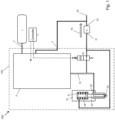
Fig. 1 shows a fuel injection system according to an embodiment of the present invention; -
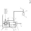
Fig. 2 shows a fuel injection system according to another embodiment of the present invention; and -
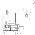
Figs. 3 and4 show a control valve arrangement according to an embodiment of the present invention. - The drawings show diagrammatic exemplifying embodiments of the present invention and are thus not necessarily drawn to scale. It shall be understood that the embodiments shown and described are exemplifying and that the invention is not limited to these embodiments. It shall also be noted that some details in the drawings may be exaggerated in order to better describe and illustrate the invention. Like reference characters refer to like elements throughout the description, unless expressed otherwise.
- Embodiments of the present invention will now be described with respect to
figs. 1-4 which show schematic sectional views of afuel injection system 100 for an internal combustion engine (not shown). The internal combustion engine may be part of a vehicle (not shown), such as a truck, a bus, a passenger car and a construction equipment vehicle. - With reference to e.g.
fig. 1 , afuel injection system 100 for an internal combustion engine is shown. Thesystem 100 comprises afirst fuel source 1 for providing fuel of a relatively high pressure. It further comprises areturn channel 50 connected to a second fuel source (not shown) for accommodating fuel of relatively low pressure in relation to the pressure of the fuel provided from thefirst fuel source 1. The second fuel source is preferably a fuel tank of the vehicle and/or the first fuel source is preferably fluidly connected to the fuel tank, whereby the fuel pressure in the first fuel source may be provided by a high-pressure pump which pumps fuel from the fuel tank. - Furthermore, the
system 100 comprises aresidual pressure regulator 5 comprising aninlet 51 and anoutlet 52, whichoutlet 52 is connected to thereturn channel 50. Thesystem 100 further comprises afuel injector 101 comprising aninlet channel 2 connected to thefirst fuel source 1, acontrol valve arrangement 3 comprising an inlet, an outlet and areturn port 4, whereby the inlet of thecontrol valve arrangement 3 is connected to theinlet channel 2 and the outlet of thecontrol valve arrangement 3 is connected to anoutlet channel 15. Thefuel injector 101 further comprises afuel injection nozzle 27 comprising anoutlet chamber 28 connected to theoutlet channel 15, aninjection outlet 32 connected to theoutlet chamber 28 and aneedle member 30, wherein theneedle member 30 is at least partially provided in theoutlet chamber 28 and biased at least partially by a biasingmember 31 to a nozzle closed position whereby fluid communication between theoutlet chamber 28 and theinjection outlet 32 is blocked. Thefuel injection nozzle 27 is configured such that theneedle member 30 is biased to open fluid communication between theoutlet chamber 28 and theinjection outlet 32 by a pressure in theoutlet chamber 28. - The
fuel injection system 100 further comprises aspill valve 40 provided between theoutlet channel 15 and thereturn channel 50, wherein theresidual pressure regulator 5 is connected by itsinlet 51 to thespill valve 40 and configured to regulate pressure at itsinlet 51 to a residual pressure that is higher than the pressure in thereturn channel 50 but lower than the pressure of thefirst fuel source 1. Further, thereturn port 4 is connected to thereturn channel 50 downstream theresidual pressure regulator 5, i.e. after theoutlet 52 of theresidual pressure regulator 5 as shown in e.g.fig. 1 . Thearrow 53 shows the direction of the flow when it flows downstream towards thereturn channel 50. Thespill valve 40 is configured to close the connection between theoutlet channel 15 and theinlet 51 of thepressure regulator 5 during a fuel injection event, and to open the connection between consecutive fuel injection events. The opening and closing of thespill valve 40 is preferably performed by anelectronic controller 11, which also, as shown, may be used for controlling thecontrol valve arrangement 3. - The biasing
member 31, which here is in the form of a coil spring, is provided in a fuel injectionnozzle control chamber 29 of thefuel injection nozzle 27. The fuel injectionnozzle control chamber 29 may be fluidly connected to theinlet 51 of thepressure regulator 5 downstream thespill valve 40. A pressure in the fuel injectionnozzle control chamber 29 may bias thefuel injection nozzle 27 to a closed position. - The
fuel injection nozzle 27 may be configured to open fluid communication between theoutlet chamber 28 and theinjection outlet 32 when the pressure in theoutlet chamber 28 is at or above a predetermined nozzle opening pressure, and the residual pressure may be set lower than the predetermined nozzle opening pressure. Thefuel injection nozzle 27 may further be configured to close when the pressure in theoutlet chamber 28 is at or below a predetermined nozzle closing pressure, while the residual pressure may be set lower than the predetermined nozzle closing pressure. Thereby, the risk of leakage at theinjection outlet 32 due to wear or damage of thefuel injection nozzle 27 may be reduced or prevented between consecutive fuel injection events. - With respect to
fig. 2 , afuel injection system 100 is shown comprising a control valve arrangement 3' which comprises anozzle control member 9 and afuel outlet chamber 17 which connects the inlet and the outlet of the control valve arrangement 3', wherein thenozzle control member 9 is at least partially arranged in thefuel outlet chamber 17 and configured to be moveable for selectively allowing pressurized fuel into theoutlet channel 15, wherein the control valve arrangement 3' further comprises afuel control chamber 12 configured such that a pressure therein biases thenozzle control member 9 towards a closed position in which pressurized fuel is prevented from being allowed into theoutlet channel 15. Thefuel control chamber 12 is connected to thereturn port 4, wherein the control valve arrangement 3' further comprises avalve member 6 configured to be moveable for selectively opening and closing aflow passage 26 between thefuel control chamber 12 and thereturn port 4. - The control valve arrangement of
fig. 2 further comprises a biasingmember 25 which biases thenozzle control member 9 towards a closed position in which fluid communication between thefuel outlet chamber 17 and theoutlet channel 15 is prevented. The biasingmember 25 is here a resilient member in the form of a coil spring. Further, in the shown embodiment, thecoil spring 25 abuts anabutment surface 14 which is provided in thefuel outlet chamber 17. - The control valve arrangement 3' further comprises a
moveable member 7, whereby at least themoveable member 7 and thenozzle control member 9 define thefuel control chamber 12. Themoveable member 7 may for example be a piston member which is moveable, e.g. slidable, in aguide 19 of the control valve arrangement 3'. Theguide 19 may for example be cylindrically formed, and arranged to accommodate at least themoveable member 7 and thenozzle control member 9, which preferably are coaxially arranged in theguide 19. Themembers guide 19 by its diameters so as to limit fluid leakage that may occur along theguide 19, which is dependent on the clearance between theguide 19 and the guidedmembers guide 19. - The
moveable member 7 is configured to be moveable towards and away from thenozzle control member 9 and to raise pressure in thefuel control chamber 12 when moved towards thenozzle control member 9. Further, thevalve member 6 is biased towards themoveable member 7 for closing theflow passage 26 and for moving themoveable member 7 towards thenozzle control member 9. The control valve arrangement 3' further comprises a fuel connection 23 between theinlet channel 2 and thefuel control chamber 12 for pressurizing thefuel control chamber 12. The fuel connection 23 preferably comprises a hydraulic restrictor 24 for restricting the flow of pressurized fuel from theinlet channel 2 to thefuel control chamber 12. Theflow passage 26 is in the shown embodiment provided in themoveable member 7. More particularly, theflow passage 26 is here provided as a centrally placed bore in themoveable member 7 which extends in the longitudinal direction relative to the cylindrically formedguide 19. - The
valve member 6 is biased towards themoveable member 7 by a secondresilient member 16. The secondresilient member 16 is here in the form of a coil spring. Thevalve member 6 and the secondresilient member 16 are here part of avalve 8, which preferably is an electronically controlled valve such as a solenoid valve, controlled by acontroller 11. - Still further, the control valve arrangement 3' comprises a
first abutment surface 10, whereby themoveable member 7 is configured to be moved towards thefirst abutment surface 10 and to contact thefirst abutment surface 10 by a pressure rise in thefuel control chamber 12. Moreover, thefirst abutment surface 10 and themoveable member 7 are configured such that fuel leakage is minimized or prevented between the contacting surfaces of thefirst abutment surface 10 and themoveable member 7. Thus, thefirst abutment surface 10 may act as a valve seat when in contact with themoveable member 7, preventing a leakage of fuel from thefuel control chamber 12 past theguide 19 and out to thereturn port 4. Furthermore, theflow control system 1 is also configured so that when themoveable member 7 and/or thenozzle control member 9 are moved towards each other, a flow area between thefuel control chamber 12 and theflow passage 26 may be reduced, and thereby leakage from thefuel control chamber 12 to thereturn port 4 may be reduced. - For example, when the
nozzle control member 9 is moved towards an open position in which the pressurized fuel is being allowed into theoutlet channel 15, aportion 13 of thenozzle control member 9 reduces the flow area between thefuel control chamber 12 and theflow passage 26. Fuel leakage from theinlet channel 2 to thereturn port 4 can thereby be limited when thenozzle control member 9 is moved towards the open position and when it is in the fully open position. Theportion 13 is in the shown embodiment coneshaped and protrudes towards themoveable member 7 so that the apex of the cone will be received in theflow passage 26 when thenozzle control member 9 and themoveable member 7 are moved towards each other. This may lead to that the flow area between thefuel control chamber 12 and theflow passage 26 is hydraulically blocked when themembers -
Fig. 2 andfigs. 3-4 further show an example of an opening and closing sequence of the control valve arrangement 3' when thenozzle control member 9 is moved between its closed and open positions. Details of thefuel injection nozzle 27 have been omitted infigs. 3 and4 . - To initiate injection, a
solenoid valve 8 is energized, which is controlled by thecontroller 11, and thereby thevalve member 6 is attracted against the force of thespring 16. This opens the connection between thefuel control chamber 12 and thereturn port 4, seefig. 3 . The flow area of theflow passage 26, which is opened by thevalve member 6, is configured to be sufficiently big to drop the pressure in thefuel control chamber 12. This may also be facilitated by use of the hydraulic restrictor 24 provided in the fuel connection 23, which restrictor 24 is configured to feed thefuel control chamber 12 with fuel with a predetermined feeding rate. This causes a positive pressure difference between thefuel outlet chamber 17 and thefuel control chamber 12, and the control valve arrangement 3' is adapted so that the positive pressure difference overcomes the force of the biasingmember 25. This leads to that thenozzle control member 9 is moved from its closed position to an open position where the connection between thefuel outlet chamber 17 and theoutlet channel 15 is opened. This causes fuel to flow from theinlet channel 2 to theoutlet channel 15. - When the
nozzle control member 9 moves upwards in theguide 19 towards themoveable member 7, the flow area between thefuel control chamber 12 and theflow passage 26 becomes restricted. This limits the flow of fuel from theinlet channel 2 via the fuel connection 23 and thefuel control chamber 12 out to thereturn port 4, and thus limits control leakage of thefuel injection system 100. This state is shown infig. 3 . - To stop an injection, the
solenoid valve 8 is de-energized, resulting in that thespring 16 makes thevalve member 6 close the connection between theflow passage 26 and thereturn channel 4, seefig. 4 . This raises the pressure in thefuel control chamber 12. The pressure rise may happen relatively slowly due to the hydraulic restrictor 24. However, by the configuration of thefuel injection system 100, and especially by use of themoveable member 7, the response time may be improved. More particularly, the force of thespring 16 acting on thevalve member 6 is transferred to themoveable member 7 when thevalve member 6 and themoveable member 7 contact each other. Thereby themoveable member 7 is moved from itsabutment surface 10 towards thenozzle control member 9, resulting in an extra pressure increase in thefuel control chamber 12. This shortens the time it takes for thenozzle control member 9 to begin its movement towards its closed position where the connection between thefuel outlet chamber 17 and theoutlet channel 15 is closed. The closer thenozzle control member 9 is to its fully closed position, the bigger the throttling effect it creates resulting in a pressure reduction in theoutlet channel 15. Since the pressure in theoutlet channel 15 also acts on thenozzle control member 9 in the direction of its opening, the increasing throttling effect accelerates the closure of thenozzle control member 9. Thus, the closing is accomplished by the throttling effect and by thespring 25, while the pressure rise in thefuel control chamber 12 moves themoveable member 7 back to theabutment surface 10. Then thesystem 1 is brought back to its initial position as shown infig. 2 , ready for the next injection cycle.
Claims (12)
- A fuel injection system (100) for an internal combustion engine, comprising:- a first fuel source (1) for providing fuel of a relatively high pressure;- a return channel (50) connected to a second fuel source for accommodating fuel of relatively low pressure in relation to the pressure of the fuel provided from the first fuel source (1);- a residual pressure regulator (5) comprising an inlet (51) and an outlet (52), which outlet is connected to the return channel (50);- a fuel injector (101) comprising an inlet channel (2) connected to the first fuel source (1), a control valve arrangement (3, 3') comprising an inlet, an outlet and a return port (4), whereby the inlet of the control valve arrangement (3) is connected to the inlet channel (2) and the outlet of the control valve arrangement (3) is connected to an outlet channel (15), wherein the fuel injector (101) further comprises a fuel injection nozzle (27) comprising an outlet chamber (28) connected to the outlet channel (15), an injection outlet (32) connected to the outlet chamber (28) and a needle member (30), wherein the needle member (30) is at least partially provided in the outlet chamber (28) and biased at least partially by a biasing member (31) to a nozzle closed position whereby fluid communication between the outlet chamber (28) and the injection outlet (32) is blocked, and wherein the fuel injection nozzle (27) is configured such that the needle member (30) is biased to open fluid communication between the outlet chamber (28) and the injection outlet (32) by a pressure in the outlet chamber (28); andwherein the fuel injection system (100) further comprises:- a spill valve (40) provided between the outlet channel (15) and the return channel (50), wherein the residual pressure regulator (5) is connected by its inlet (51) to the spill valve (40) and configured to regulate pressure at its inlet (51) to a residual pressure that is higher than the pressure in the return channel (50) but lower than the pressure of the first fuel source (1), characterized in that further the return port (4) is connected to the return channel (50) downstream the residual pressure regulator (5).
- The fuel injection system (100) according to claim 1, wherein the fuel injection nozzle (27) is configured to open fluid communication between the outlet chamber (28) and the injection outlet (32) when the pressure in the outlet chamber (28) is at or above a predetermined nozzle opening pressure, further wherein the residual pressure is set lower than the predetermined nozzle opening pressure.
- The fuel injection system (100) according to any one of the preceding claims, wherein the fuel injection nozzle (27) is configured to close when the pressure in the outlet chamber (28) is at or below a predetermined nozzle closing pressure, further wherein the residual pressure is set lower than the predetermined nozzle closing pressure.
- The fuel injection system (100) according to any one of the preceding claims, wherein the residual pressure is set to a level between 25 and 65 bar.
- The fuel injection system (100) according to any one of the preceding claims, wherein the control valve arrangement (3') further comprises a nozzle control member (9) and a fuel outlet chamber (17) which connects the inlet and the outlet of the control valve arrangement (3), wherein the nozzle control member (9) is at least partially arranged in the fuel outlet chamber (17) and configured to be moveable for selectively allowing pressurized fuel into the outlet channel (15), wherein the control valve arrangement (3) further comprises a fuel control chamber (12) configured such that a pressure therein biases the nozzle control member (9) towards a closed position in which pressurized fuel is prevented from being allowed into the outlet channel (15), wherein the fuel control chamber (12) is connected to the return port (4), and wherein the control valve arrangement (3) further comprises a valve member (6) configured to be moveable for selectively opening and closing a flow passage (26) between the fuel control chamber (12) and the return port (4).
- The fuel injection system (100) according to claim 5, wherein the control valve arrangement (3) further comprises a moveable member (7), whereby at least the moveable member (7) and the nozzle control member (9) define the fuel control chamber (12).
- The fuel injection system (100) according to claim 6, wherein the moveable member (7) is configured to be moveable towards and away from the nozzle control member (9) and to raise pressure in the fuel control chamber (12) when moved towards the nozzle control member (9), and wherein the valve member (6) is biased towards the moveable member for closing the flow passage (26) and for moving the moveable member towards the nozzle control member (9).
- The fuel injection system (100) according to any one of claims 5-7, wherein the valve member (6) is part of an electronically controlled valve.
- The fuel injection system (100) according to any one of claims 5-8, further comprising a fuel connection between the inlet channel (2) and the fuel control chamber (12) for pressurizing the fuel control chamber (12).
- The fuel injection system (100) according to claim 9, wherein the fuel connection comprises a hydraulic restrictor (24) for restricting the flow of fuel from the inlet channel (2) to the fuel control chamber (12).
- The fuel injection system (100) according to any one of claims 5-10, further comprising a biasing member (25) biasing the nozzle control member towards its closed position.
- A vehicle comprising the fuel injection system according to any one of claims 1-11.
Applications Claiming Priority (1)
| Application Number | Priority Date | Filing Date | Title |
|---|---|---|---|
| PCT/EP2019/073041 WO2021037365A1 (en) | 2019-08-29 | 2019-08-29 | A fuel injection system |
Publications (2)
| Publication Number | Publication Date |
|---|---|
| EP4022183A1 EP4022183A1 (en) | 2022-07-06 |
| EP4022183B1 true EP4022183B1 (en) | 2024-07-03 |
Family
ID=67874421
Family Applications (1)
| Application Number | Title | Priority Date | Filing Date |
|---|---|---|---|
| EP19765190.4A Active EP4022183B1 (en) | 2019-08-29 | 2019-08-29 | A fuel injection system |
Country Status (4)
| Country | Link |
|---|---|
| US (1) | US11988179B2 (en) |
| EP (1) | EP4022183B1 (en) |
| CN (1) | CN114270028A (en) |
| WO (1) | WO2021037365A1 (en) |
Family Cites Families (17)
| Publication number | Priority date | Publication date | Assignee | Title |
|---|---|---|---|---|
| DE19939428A1 (en) * | 1999-08-20 | 2001-03-01 | Bosch Gmbh Robert | Method and device for performing a fuel injection |
| JP2003206824A (en) * | 2001-11-09 | 2003-07-25 | Bosch Automotive Systems Corp | Injection pump, dme fuel supply device of diesel engine having it |
| US7191762B2 (en) * | 2002-03-26 | 2007-03-20 | Volvo Lastvagnar Ab | Fuel injection system |
| US7100573B2 (en) * | 2002-04-23 | 2006-09-05 | Volvo Lastvagnar Ab | Fuel injection system |
| SE524416C2 (en) * | 2002-04-23 | 2004-08-03 | Volvo Lastvagnar Ab | Fuel injection systems |
| JP3935829B2 (en) * | 2002-11-20 | 2007-06-27 | 三菱重工業株式会社 | Internal combustion engine leak fuel recovery device |
| DE102004010760A1 (en) * | 2004-03-05 | 2005-09-22 | Robert Bosch Gmbh | Fuel injection device for internal combustion engines with Nadelhubdämpfung |
| CN101297108B (en) * | 2005-10-19 | 2012-02-01 | 沃尔沃拉斯特瓦格纳公司 | Fuel oil injection system suitable for low-viscosity fuel oil |
| WO2007105991A1 (en) * | 2006-03-10 | 2007-09-20 | Volvo Lastvagnar Ab | Fuel injection system |
| US7730876B2 (en) * | 2006-03-30 | 2010-06-08 | Volvo Lastvagnar Ab | Fuel injection system |
| SE536105C2 (en) * | 2008-03-04 | 2013-05-07 | Volvo Lastvagnar Ab | Fuel injection system for an internal combustion engine and vehicle including such a fuel injection system |
| WO2013102467A1 (en) * | 2012-01-03 | 2013-07-11 | Volvo Lastvagnar Ab | Fuel system and corresponding method |
| EP2674608B1 (en) * | 2012-06-13 | 2015-08-12 | Delphi International Operations Luxembourg S.à r.l. | Fuel injector |
| CN104662282B (en) * | 2012-08-08 | 2017-06-20 | 沃尔沃拉斯特瓦格纳公司 | Flow system |
| JP5672287B2 (en) * | 2012-10-11 | 2015-02-18 | 株式会社デンソー | Fuel injection device |
| KR101361347B1 (en) * | 2012-12-28 | 2014-02-10 | 현대자동차주식회사 | Common rail system for dme fuel |
| JP6115523B2 (en) * | 2014-07-03 | 2017-04-19 | 株式会社デンソー | Fuel supply device |
-
2019
- 2019-08-29 US US17/638,532 patent/US11988179B2/en active Active
- 2019-08-29 EP EP19765190.4A patent/EP4022183B1/en active Active
- 2019-08-29 CN CN201980099637.1A patent/CN114270028A/en active Pending
- 2019-08-29 WO PCT/EP2019/073041 patent/WO2021037365A1/en not_active Ceased
Also Published As
| Publication number | Publication date |
|---|---|
| CN114270028A (en) | 2022-04-01 |
| US11988179B2 (en) | 2024-05-21 |
| WO2021037365A1 (en) | 2021-03-04 |
| US20220356859A1 (en) | 2022-11-10 |
| EP4022183A1 (en) | 2022-07-06 |
Similar Documents
| Publication | Publication Date | Title |
|---|---|---|
| EP0531533B1 (en) | Pressure accumulation type fuel jetting device | |
| US8162623B2 (en) | High-pressure liquid supply pump | |
| US6814302B2 (en) | Accumulator fuel-injection system for an internal combustion engine | |
| US7278593B2 (en) | Common rail fuel injector | |
| EP1941154B1 (en) | Fuel injection system suitable for low-viscosity fuels | |
| EP2249021A1 (en) | Fuel Delivery System | |
| EP2882955B1 (en) | Flow control system | |
| EP3574203B1 (en) | Positive sealing proportional control valve with sealable vent valve | |
| KR20110010825A (en) | How to control high pressure fuel pump | |
| WO2016024038A1 (en) | A fuel injection valve arrangement for internal combustion engine | |
| US11988179B2 (en) | Fuel injection system | |
| US7216669B2 (en) | Pressure regulating valve for common rail fuel injection systems | |
| EP3994350B1 (en) | A flow control system | |
| WO2015043742A2 (en) | A fuel injection system for an internal combustion engine and a method of controlling fuel injection into an internal combustion engine | |
| JP6483196B2 (en) | High pressure fuel supply pump | |
| US11236717B2 (en) | Assembly having a high-pressure pump and a control device arranged upstream of the high-pressure pump | |
| CN111989481B (en) | Fuel supply pump and method for manufacturing fuel supply pump | |
| US20130140478A1 (en) | Two-Way Needle Control Valve |
Legal Events
| Date | Code | Title | Description |
|---|---|---|---|
| STAA | Information on the status of an ep patent application or granted ep patent |
Free format text: STATUS: UNKNOWN |
|
| STAA | Information on the status of an ep patent application or granted ep patent |
Free format text: STATUS: THE INTERNATIONAL PUBLICATION HAS BEEN MADE |
|
| PUAI | Public reference made under article 153(3) epc to a published international application that has entered the european phase |
Free format text: ORIGINAL CODE: 0009012 |
|
| STAA | Information on the status of an ep patent application or granted ep patent |
Free format text: STATUS: REQUEST FOR EXAMINATION WAS MADE |
|
| 17P | Request for examination filed |
Effective date: 20220323 |
|
| AK | Designated contracting states |
Kind code of ref document: A1 Designated state(s): AL AT BE BG CH CY CZ DE DK EE ES FI FR GB GR HR HU IE IS IT LI LT LU LV MC MK MT NL NO PL PT RO RS SE SI SK SM TR |
|
| DAV | Request for validation of the european patent (deleted) | ||
| DAX | Request for extension of the european patent (deleted) | ||
| REG | Reference to a national code |
Ref country code: DE Ref legal event code: R079 Free format text: PREVIOUS MAIN CLASS: F02M0047020000 Ipc: F02M0021020000 Ref country code: DE Ref legal event code: R079 Ref document number: 602019054620 Country of ref document: DE Free format text: PREVIOUS MAIN CLASS: F02M0047020000 Ipc: F02M0021020000 |
|
| RIC1 | Information provided on ipc code assigned before grant |
Ipc: F02M 21/02 20060101AFI20231221BHEP |
|
| GRAP | Despatch of communication of intention to grant a patent |
Free format text: ORIGINAL CODE: EPIDOSNIGR1 |
|
| STAA | Information on the status of an ep patent application or granted ep patent |
Free format text: STATUS: GRANT OF PATENT IS INTENDED |
|
| INTG | Intention to grant announced |
Effective date: 20240129 |
|
| GRAS | Grant fee paid |
Free format text: ORIGINAL CODE: EPIDOSNIGR3 |
|
| GRAA | (expected) grant |
Free format text: ORIGINAL CODE: 0009210 |
|
| STAA | Information on the status of an ep patent application or granted ep patent |
Free format text: STATUS: THE PATENT HAS BEEN GRANTED |
|
| AK | Designated contracting states |
Kind code of ref document: B1 Designated state(s): AL AT BE BG CH CY CZ DE DK EE ES FI FR GB GR HR HU IE IS IT LI LT LU LV MC MK MT NL NO PL PT RO RS SE SI SK SM TR |
|
| REG | Reference to a national code |
Ref country code: CH Ref legal event code: EP |
|
| REG | Reference to a national code |
Ref country code: DE Ref legal event code: R096 Ref document number: 602019054620 Country of ref document: DE |
|
| REG | Reference to a national code |
Ref country code: NL Ref legal event code: FP |
|
| PGFP | Annual fee paid to national office [announced via postgrant information from national office to epo] |
Ref country code: FR Payment date: 20240709 Year of fee payment: 6 |
|
| REG | Reference to a national code |
Ref country code: LT Ref legal event code: MG9D |
|
| PG25 | Lapsed in a contracting state [announced via postgrant information from national office to epo] |
Ref country code: PT Free format text: LAPSE BECAUSE OF FAILURE TO SUBMIT A TRANSLATION OF THE DESCRIPTION OR TO PAY THE FEE WITHIN THE PRESCRIBED TIME-LIMIT Effective date: 20241104 |
|
| REG | Reference to a national code |
Ref country code: AT Ref legal event code: MK05 Ref document number: 1700050 Country of ref document: AT Kind code of ref document: T Effective date: 20240703 |
|
| PG25 | Lapsed in a contracting state [announced via postgrant information from national office to epo] |
Ref country code: PT Free format text: LAPSE BECAUSE OF FAILURE TO SUBMIT A TRANSLATION OF THE DESCRIPTION OR TO PAY THE FEE WITHIN THE PRESCRIBED TIME-LIMIT Effective date: 20241104 |
|
| PG25 | Lapsed in a contracting state [announced via postgrant information from national office to epo] |
Ref country code: NO Free format text: LAPSE BECAUSE OF FAILURE TO SUBMIT A TRANSLATION OF THE DESCRIPTION OR TO PAY THE FEE WITHIN THE PRESCRIBED TIME-LIMIT Effective date: 20241003 |
|
| PG25 | Lapsed in a contracting state [announced via postgrant information from national office to epo] |
Ref country code: GR Free format text: LAPSE BECAUSE OF FAILURE TO SUBMIT A TRANSLATION OF THE DESCRIPTION OR TO PAY THE FEE WITHIN THE PRESCRIBED TIME-LIMIT Effective date: 20241004 Ref country code: FI Free format text: LAPSE BECAUSE OF FAILURE TO SUBMIT A TRANSLATION OF THE DESCRIPTION OR TO PAY THE FEE WITHIN THE PRESCRIBED TIME-LIMIT Effective date: 20240703 Ref country code: PL Free format text: LAPSE BECAUSE OF FAILURE TO SUBMIT A TRANSLATION OF THE DESCRIPTION OR TO PAY THE FEE WITHIN THE PRESCRIBED TIME-LIMIT Effective date: 20240703 |
|
| PG25 | Lapsed in a contracting state [announced via postgrant information from national office to epo] |
Ref country code: BG Free format text: LAPSE BECAUSE OF FAILURE TO SUBMIT A TRANSLATION OF THE DESCRIPTION OR TO PAY THE FEE WITHIN THE PRESCRIBED TIME-LIMIT Effective date: 20240703 |
|
| PG25 | Lapsed in a contracting state [announced via postgrant information from national office to epo] |
Ref country code: LV Free format text: LAPSE BECAUSE OF FAILURE TO SUBMIT A TRANSLATION OF THE DESCRIPTION OR TO PAY THE FEE WITHIN THE PRESCRIBED TIME-LIMIT Effective date: 20240703 |
|
| PG25 | Lapsed in a contracting state [announced via postgrant information from national office to epo] |
Ref country code: IS Free format text: LAPSE BECAUSE OF FAILURE TO SUBMIT A TRANSLATION OF THE DESCRIPTION OR TO PAY THE FEE WITHIN THE PRESCRIBED TIME-LIMIT Effective date: 20241103 Ref country code: AT Free format text: LAPSE BECAUSE OF FAILURE TO SUBMIT A TRANSLATION OF THE DESCRIPTION OR TO PAY THE FEE WITHIN THE PRESCRIBED TIME-LIMIT Effective date: 20240703 |
|
| PG25 | Lapsed in a contracting state [announced via postgrant information from national office to epo] |
Ref country code: HR Free format text: LAPSE BECAUSE OF FAILURE TO SUBMIT A TRANSLATION OF THE DESCRIPTION OR TO PAY THE FEE WITHIN THE PRESCRIBED TIME-LIMIT Effective date: 20240703 Ref country code: CZ Free format text: LAPSE BECAUSE OF FAILURE TO SUBMIT A TRANSLATION OF THE DESCRIPTION OR TO PAY THE FEE WITHIN THE PRESCRIBED TIME-LIMIT Effective date: 20240703 |
|
| PG25 | Lapsed in a contracting state [announced via postgrant information from national office to epo] |
Ref country code: RS Free format text: LAPSE BECAUSE OF FAILURE TO SUBMIT A TRANSLATION OF THE DESCRIPTION OR TO PAY THE FEE WITHIN THE PRESCRIBED TIME-LIMIT Effective date: 20241003 Ref country code: ES Free format text: LAPSE BECAUSE OF FAILURE TO SUBMIT A TRANSLATION OF THE DESCRIPTION OR TO PAY THE FEE WITHIN THE PRESCRIBED TIME-LIMIT Effective date: 20240703 |
|
| PG25 | Lapsed in a contracting state [announced via postgrant information from national office to epo] |
Ref country code: RS Free format text: LAPSE BECAUSE OF FAILURE TO SUBMIT A TRANSLATION OF THE DESCRIPTION OR TO PAY THE FEE WITHIN THE PRESCRIBED TIME-LIMIT Effective date: 20241003 Ref country code: PL Free format text: LAPSE BECAUSE OF FAILURE TO SUBMIT A TRANSLATION OF THE DESCRIPTION OR TO PAY THE FEE WITHIN THE PRESCRIBED TIME-LIMIT Effective date: 20240703 Ref country code: NO Free format text: LAPSE BECAUSE OF FAILURE TO SUBMIT A TRANSLATION OF THE DESCRIPTION OR TO PAY THE FEE WITHIN THE PRESCRIBED TIME-LIMIT Effective date: 20241003 Ref country code: LV Free format text: LAPSE BECAUSE OF FAILURE TO SUBMIT A TRANSLATION OF THE DESCRIPTION OR TO PAY THE FEE WITHIN THE PRESCRIBED TIME-LIMIT Effective date: 20240703 Ref country code: IS Free format text: LAPSE BECAUSE OF FAILURE TO SUBMIT A TRANSLATION OF THE DESCRIPTION OR TO PAY THE FEE WITHIN THE PRESCRIBED TIME-LIMIT Effective date: 20241103 Ref country code: HR Free format text: LAPSE BECAUSE OF FAILURE TO SUBMIT A TRANSLATION OF THE DESCRIPTION OR TO PAY THE FEE WITHIN THE PRESCRIBED TIME-LIMIT Effective date: 20240703 Ref country code: GR Free format text: LAPSE BECAUSE OF FAILURE TO SUBMIT A TRANSLATION OF THE DESCRIPTION OR TO PAY THE FEE WITHIN THE PRESCRIBED TIME-LIMIT Effective date: 20241004 Ref country code: FI Free format text: LAPSE BECAUSE OF FAILURE TO SUBMIT A TRANSLATION OF THE DESCRIPTION OR TO PAY THE FEE WITHIN THE PRESCRIBED TIME-LIMIT Effective date: 20240703 Ref country code: ES Free format text: LAPSE BECAUSE OF FAILURE TO SUBMIT A TRANSLATION OF THE DESCRIPTION OR TO PAY THE FEE WITHIN THE PRESCRIBED TIME-LIMIT Effective date: 20240703 Ref country code: CZ Free format text: LAPSE BECAUSE OF FAILURE TO SUBMIT A TRANSLATION OF THE DESCRIPTION OR TO PAY THE FEE WITHIN THE PRESCRIBED TIME-LIMIT Effective date: 20240703 Ref country code: BG Free format text: LAPSE BECAUSE OF FAILURE TO SUBMIT A TRANSLATION OF THE DESCRIPTION OR TO PAY THE FEE WITHIN THE PRESCRIBED TIME-LIMIT Effective date: 20240703 Ref country code: AT Free format text: LAPSE BECAUSE OF FAILURE TO SUBMIT A TRANSLATION OF THE DESCRIPTION OR TO PAY THE FEE WITHIN THE PRESCRIBED TIME-LIMIT Effective date: 20240703 |
|
| REG | Reference to a national code |
Ref country code: CH Ref legal event code: PL |
|
| REG | Reference to a national code |
Ref country code: DE Ref legal event code: R097 Ref document number: 602019054620 Country of ref document: DE |
|
| PG25 | Lapsed in a contracting state [announced via postgrant information from national office to epo] |
Ref country code: DK Free format text: LAPSE BECAUSE OF FAILURE TO SUBMIT A TRANSLATION OF THE DESCRIPTION OR TO PAY THE FEE WITHIN THE PRESCRIBED TIME-LIMIT Effective date: 20240703 Ref country code: RO Free format text: LAPSE BECAUSE OF FAILURE TO SUBMIT A TRANSLATION OF THE DESCRIPTION OR TO PAY THE FEE WITHIN THE PRESCRIBED TIME-LIMIT Effective date: 20240703 Ref country code: SM Free format text: LAPSE BECAUSE OF FAILURE TO SUBMIT A TRANSLATION OF THE DESCRIPTION OR TO PAY THE FEE WITHIN THE PRESCRIBED TIME-LIMIT Effective date: 20240703 |
|
| PG25 | Lapsed in a contracting state [announced via postgrant information from national office to epo] |
Ref country code: LU Free format text: LAPSE BECAUSE OF NON-PAYMENT OF DUE FEES Effective date: 20240829 |
|
| PG25 | Lapsed in a contracting state [announced via postgrant information from national office to epo] |
Ref country code: CH Free format text: LAPSE BECAUSE OF NON-PAYMENT OF DUE FEES Effective date: 20240831 Ref country code: EE Free format text: LAPSE BECAUSE OF FAILURE TO SUBMIT A TRANSLATION OF THE DESCRIPTION OR TO PAY THE FEE WITHIN THE PRESCRIBED TIME-LIMIT Effective date: 20240703 Ref country code: MC Free format text: LAPSE BECAUSE OF FAILURE TO SUBMIT A TRANSLATION OF THE DESCRIPTION OR TO PAY THE FEE WITHIN THE PRESCRIBED TIME-LIMIT Effective date: 20240703 |
|
| PG25 | Lapsed in a contracting state [announced via postgrant information from national office to epo] |
Ref country code: SK Free format text: LAPSE BECAUSE OF FAILURE TO SUBMIT A TRANSLATION OF THE DESCRIPTION OR TO PAY THE FEE WITHIN THE PRESCRIBED TIME-LIMIT Effective date: 20240703 Ref country code: IT Free format text: LAPSE BECAUSE OF FAILURE TO SUBMIT A TRANSLATION OF THE DESCRIPTION OR TO PAY THE FEE WITHIN THE PRESCRIBED TIME-LIMIT Effective date: 20240703 |
|
| PLBE | No opposition filed within time limit |
Free format text: ORIGINAL CODE: 0009261 |
|
| STAA | Information on the status of an ep patent application or granted ep patent |
Free format text: STATUS: NO OPPOSITION FILED WITHIN TIME LIMIT |
|
| 26N | No opposition filed |
Effective date: 20250404 |
|
| GBPC | Gb: european patent ceased through non-payment of renewal fee |
Effective date: 20241003 |
|
| REG | Reference to a national code |
Ref country code: BE Ref legal event code: MM Effective date: 20240831 |
|
| PG25 | Lapsed in a contracting state [announced via postgrant information from national office to epo] |
Ref country code: GB Free format text: LAPSE BECAUSE OF NON-PAYMENT OF DUE FEES Effective date: 20241003 |
|
| PG25 | Lapsed in a contracting state [announced via postgrant information from national office to epo] |
Ref country code: BE Free format text: LAPSE BECAUSE OF NON-PAYMENT OF DUE FEES Effective date: 20240831 |
|
| PG25 | Lapsed in a contracting state [announced via postgrant information from national office to epo] |
Ref country code: IE Free format text: LAPSE BECAUSE OF NON-PAYMENT OF DUE FEES Effective date: 20240829 |
|
| PG25 | Lapsed in a contracting state [announced via postgrant information from national office to epo] |
Ref country code: SE Free format text: LAPSE BECAUSE OF FAILURE TO SUBMIT A TRANSLATION OF THE DESCRIPTION OR TO PAY THE FEE WITHIN THE PRESCRIBED TIME-LIMIT Effective date: 20240703 |
|
| PGFP | Annual fee paid to national office [announced via postgrant information from national office to epo] |
Ref country code: NL Payment date: 20250825 Year of fee payment: 7 |
|
| PGFP | Annual fee paid to national office [announced via postgrant information from national office to epo] |
Ref country code: DE Payment date: 20250827 Year of fee payment: 7 |
|
| PG25 | Lapsed in a contracting state [announced via postgrant information from national office to epo] |
Ref country code: CY Free format text: LAPSE BECAUSE OF FAILURE TO SUBMIT A TRANSLATION OF THE DESCRIPTION OR TO PAY THE FEE WITHIN THE PRESCRIBED TIME-LIMIT; INVALID AB INITIO Effective date: 20190829 |
|
| PG25 | Lapsed in a contracting state [announced via postgrant information from national office to epo] |
Ref country code: HU Free format text: LAPSE BECAUSE OF FAILURE TO SUBMIT A TRANSLATION OF THE DESCRIPTION OR TO PAY THE FEE WITHIN THE PRESCRIBED TIME-LIMIT; INVALID AB INITIO Effective date: 20190829 |