EP4022182B1 - Abgasrückführsystem für eine verbrennungskraftmaschine sowie verfahren zur regelung eines derartigen abgasrückführsystems - Google Patents
Abgasrückführsystem für eine verbrennungskraftmaschine sowie verfahren zur regelung eines derartigen abgasrückführsystems Download PDFInfo
- Publication number
- EP4022182B1 EP4022182B1 EP19762749.0A EP19762749A EP4022182B1 EP 4022182 B1 EP4022182 B1 EP 4022182B1 EP 19762749 A EP19762749 A EP 19762749A EP 4022182 B1 EP4022182 B1 EP 4022182B1
- Authority
- EP
- European Patent Office
- Prior art keywords
- exhaust gas
- valve
- gas recirculation
- heat exchanger
- combustion engine
- Prior art date
- Legal status (The legal status is an assumption and is not a legal conclusion. Google has not performed a legal analysis and makes no representation as to the accuracy of the status listed.)
- Active
Links
Images
Classifications
-
- F—MECHANICAL ENGINEERING; LIGHTING; HEATING; WEAPONS; BLASTING
- F02—COMBUSTION ENGINES; HOT-GAS OR COMBUSTION-PRODUCT ENGINE PLANTS
- F02M—SUPPLYING COMBUSTION ENGINES IN GENERAL WITH COMBUSTIBLE MIXTURES OR CONSTITUENTS THEREOF
- F02M26/00—Engine-pertinent apparatus for adding exhaust gases to combustion-air, main fuel or fuel-air mixture, e.g. by exhaust gas recirculation [EGR] systems
- F02M26/13—Arrangement or layout of EGR passages, e.g. in relation to specific engine parts or for incorporation of accessories
- F02M26/22—Arrangement or layout of EGR passages, e.g. in relation to specific engine parts or for incorporation of accessories with coolers in the recirculation passage
- F02M26/23—Layout, e.g. schematics
- F02M26/25—Layout, e.g. schematics with coolers having bypasses
- F02M26/26—Layout, e.g. schematics with coolers having bypasses characterised by details of the bypass valve
-
- F—MECHANICAL ENGINEERING; LIGHTING; HEATING; WEAPONS; BLASTING
- F02—COMBUSTION ENGINES; HOT-GAS OR COMBUSTION-PRODUCT ENGINE PLANTS
- F02M—SUPPLYING COMBUSTION ENGINES IN GENERAL WITH COMBUSTIBLE MIXTURES OR CONSTITUENTS THEREOF
- F02M26/00—Engine-pertinent apparatus for adding exhaust gases to combustion-air, main fuel or fuel-air mixture, e.g. by exhaust gas recirculation [EGR] systems
- F02M26/02—EGR systems specially adapted for supercharged engines
- F02M26/09—Constructional details, e.g. structural combinations of EGR systems and supercharger systems; Arrangement of the EGR and supercharger systems with respect to the engine
- F02M26/10—Constructional details, e.g. structural combinations of EGR systems and supercharger systems; Arrangement of the EGR and supercharger systems with respect to the engine having means to increase the pressure difference between the exhaust and intake system, e.g. venturis, variable geometry turbines, check valves using pressure pulsations or throttles in the air intake or exhaust system
-
- F—MECHANICAL ENGINEERING; LIGHTING; HEATING; WEAPONS; BLASTING
- F02—COMBUSTION ENGINES; HOT-GAS OR COMBUSTION-PRODUCT ENGINE PLANTS
- F02M—SUPPLYING COMBUSTION ENGINES IN GENERAL WITH COMBUSTIBLE MIXTURES OR CONSTITUENTS THEREOF
- F02M26/00—Engine-pertinent apparatus for adding exhaust gases to combustion-air, main fuel or fuel-air mixture, e.g. by exhaust gas recirculation [EGR] systems
- F02M26/13—Arrangement or layout of EGR passages, e.g. in relation to specific engine parts or for incorporation of accessories
- F02M26/14—Arrangement or layout of EGR passages, e.g. in relation to specific engine parts or for incorporation of accessories in relation to the exhaust system
-
- F—MECHANICAL ENGINEERING; LIGHTING; HEATING; WEAPONS; BLASTING
- F02—COMBUSTION ENGINES; HOT-GAS OR COMBUSTION-PRODUCT ENGINE PLANTS
- F02M—SUPPLYING COMBUSTION ENGINES IN GENERAL WITH COMBUSTIBLE MIXTURES OR CONSTITUENTS THEREOF
- F02M26/00—Engine-pertinent apparatus for adding exhaust gases to combustion-air, main fuel or fuel-air mixture, e.g. by exhaust gas recirculation [EGR] systems
- F02M26/52—Systems for actuating EGR valves
-
- F—MECHANICAL ENGINEERING; LIGHTING; HEATING; WEAPONS; BLASTING
- F02—COMBUSTION ENGINES; HOT-GAS OR COMBUSTION-PRODUCT ENGINE PLANTS
- F02M—SUPPLYING COMBUSTION ENGINES IN GENERAL WITH COMBUSTIBLE MIXTURES OR CONSTITUENTS THEREOF
- F02M26/00—Engine-pertinent apparatus for adding exhaust gases to combustion-air, main fuel or fuel-air mixture, e.g. by exhaust gas recirculation [EGR] systems
- F02M26/65—Constructional details of EGR valves
- F02M26/66—Lift valves, e.g. poppet valves
- F02M26/69—Lift valves, e.g. poppet valves having two or more valve-closing members
-
- Y—GENERAL TAGGING OF NEW TECHNOLOGICAL DEVELOPMENTS; GENERAL TAGGING OF CROSS-SECTIONAL TECHNOLOGIES SPANNING OVER SEVERAL SECTIONS OF THE IPC; TECHNICAL SUBJECTS COVERED BY FORMER USPC CROSS-REFERENCE ART COLLECTIONS [XRACs] AND DIGESTS
- Y02—TECHNOLOGIES OR APPLICATIONS FOR MITIGATION OR ADAPTATION AGAINST CLIMATE CHANGE
- Y02T—CLIMATE CHANGE MITIGATION TECHNOLOGIES RELATED TO TRANSPORTATION
- Y02T10/00—Road transport of goods or passengers
- Y02T10/10—Internal combustion engine [ICE] based vehicles
- Y02T10/12—Improving ICE efficiencies
Definitions
- the present invention relates to an exhaust gas recirculation system for an internal combustion engine with an exhaust duct of the internal combustion engine, an inlet duct of the internal combustion engine, an exhaust gas recirculation duct that branches off from the exhaust duct and opens into the inlet duct, a heat exchanger that is arranged in the exhaust gas recirculation duct and has two separate strands, an exhaust gas recirculation valve that is arranged at the outlet of the heat exchanger, a flap valve that is arranged in the exhaust duct in such a way that the flap valve opens the exhaust duct in a first position, closes the exhaust duct downstream of the two strands in the flow direction in a second position, closes the exhaust duct in the area between the two strands in a third position and throttles the exhaust duct in a fourth position, as well as a method for controlling such an exhaust gas recirculation system.
- Exhaust gas recirculation systems are well known and are used to reduce the proportion of pollutants in combustion engines. A distinction is made between in-cylinder exhaust gas recirculation, external high-pressure exhaust gas recirculation and low-pressure exhaust gas recirculation. In low-pressure exhaust gas recirculation, it is necessary to provide an exhaust flap to increase the flow resistance in the exhaust line in order to achieve sufficiently high exhaust gas recirculation rates. It is also known to provide bypassable heat exchangers in the exhaust gas recirculation channel, through which the temperature of the recirculated exhaust gas can be reduced. can be used when necessary to reduce the combustion temperature in the engine.
- the hot exhaust gas has been used in recent years to generate heat in the motor vehicle.
- its thermal energy is used, for example, to heat up the internal combustion engine more quickly, to warm up the driver's cabin more quickly or to reduce friction losses by heating the lubricant system.
- the thermal energy is extracted from the exhaust gas via the heat exchanger of the exhaust gas recirculation system.
- a state-of-the-art exhaust gas recirculation system is known, for example, from WO 2014/136024 A1 It has a U-shaped heat exchanger which is connected to an exhaust duct and, downstream of the heat exchanger, via an exhaust gas recirculation valve to an inlet duct, via which combustion air can be fed to the internal combustion engine.
- a flap valve is arranged in the exhaust duct, which can be adjusted between a first position, in which the exhaust duct is completely open and an opening of the heat exchanger is completely closed, and a second position, in which the exhaust duct is completely closed in the area of the heat exchanger and a branch of the U-shaped heat exchanger upstream in the direction of flow is completely open, so that the exhaust gas flow is fed into this branch of the heat exchanger.
- This exhaust gas recirculation system has the disadvantage that a sufficiently high flow gradient must be present in the exhaust gas recirculation duct so that a sufficient amount of exhaust gas flows through the heat exchanger.
- This exhaust gas recirculation system is not suitable for low-pressure operation, since the resistance in the exhaust gas recirculation duct is always higher than in the exhaust duct. Accordingly, there is no sufficient controllability of the recirculated exhaust gas flow, especially in phases with high exhaust gas recirculation rates.
- the legally prescribed emission values cannot be achieved with such an exhaust gas recirculation system, especially in the low-pressure range.
- an exhaust gas recirculation system in which an exhaust gas recirculation line branches off from an exhaust gas duct, which then forks into two branches.
- a heat exchanger is arranged in the first branch behind the fork, which can be bypassed via a bypass line formed by the second branch.
- At the end of the bypass line there is a lift valve, which is connected via a common actuator to a lift valve that is arranged downstream of the heat exchanger. By operating the actuator, either the bypass channel or the cooling channel is opened. In the idle state, both branches are closed.
- the object of the present invention is therefore to create an exhaust gas recirculation system for an internal combustion engine and a method for controlling such an exhaust gas recirculation system, which is suitable for low-pressure operation and enables temperature control of the exhaust gas without the structure of the system becoming too complex. Damage to a downstream compressor should also be avoided, as should excessively long warm-up times or increased sooting of the heat exchanger due to accumulating condensate.
- the exhaust gas recirculation system has a heat exchanger with two structurally separate strands through which flow can either be U-shaped or parallel.
- the two strands are designed in such a way that mutual influence of the flows in the strands is avoided.
- they are connected to one another via a collector, so that depending on the flap position of the exhaust gas recirculation valve, either the exhaust gas from both strands is directed via the collector into the exhaust gas recirculation channel, or the exhaust gas from the first strand upstream in the exhaust gas direction in the exhaust gas channel is directed in a U-shape via the collector into the second strand.
- the exhaust gas recirculation system has a flap valve which is arranged in the exhaust gas duct in such a way that the flap valve opens the exhaust gas duct in a first position and closes the exhaust gas duct in the flow direction downstream of the two strands in a second position, so that the exhaust gas flow flows through both strands in the direction from the exhaust gas duct to the inlet channel, in a third position the flap valve closes the exhaust channel in the area between the two strands, so that the exhaust gas flow is guided through the first strand upstream in the exhaust gas direction, and the second strand is flowed through in the opposite direction depending on the position of the exhaust gas recirculation valve, whereupon the exhaust gas from the second strand flows back into the exhaust channel downstream of the flap valve, and in a fourth position the exhaust channel is throttled, i.e. only partially closed.
- the flap valve In the first position, the flap valve therefore has minimal flow resistance in the exhaust duct, so that the flow in the exhaust duct is hardly disturbed by the flap valve. In the second position, however, complete flow through the exhaust duct from the flap valve downstream of the two strands is prevented.
- the EGR valve When the EGR valve is open, the exhaust gas is diverted into both strands of the heat exchanger, so that the entire exhaust gas volume is distributed over two strands and the maximum heat exchanger cross-section is utilized. This increases the proportion of thermal energy recovered, since the temperature difference between the coolant and the exhaust gas is greater than with a U-shaped flow through the cooler.
- the heat exchanger can be bypassed via a bypass line, the flow cross-section of which can be regulated by means of a bypass valve and which branches off from the exhaust duct upstream of the flap valve.
- a bypass line the flow cross-section of which can be regulated by means of a bypass valve and which branches off from the exhaust duct upstream of the flap valve.
- hot exhaust gas can also be conveyed directly to the internal combustion engine.
- the warm-up times of the internal combustion engine can be reduced and the exhaust gas temperature can be adapted to the respective operating state.
- the tendency of the water in the exhaust gas to condense when flowing into the intake air can be reduced by the exhaust gas reaching the intake duct at higher temperatures, thereby achieving higher mixing temperatures.
- the sooting of the heat exchanger is also reduced by reducing condensation.
- the object is achieved in that after the cold start of the internal combustion engine, the flap valve closes the exhaust gas channel between the two strands of the heat exchanger, the bypass valve closes the bypass line and the exhaust gas recirculation valve closes the outlet of the heat exchanger, so that the heat exchanger is flowed through and can heat up accordingly, whereby the thermal energy can be used for recovery, for example to heat the passenger compartment.
- the flap valve opens the exhaust duct
- the bypass valve opens the bypass line
- the exhaust gas recirculation valve closes the outlet of the heat exchanger, thereby achieving rapid heating of the internal combustion engine to reduce pollutants.
- the flap valve closes the exhaust duct downstream of both strands of the heat exchanger, the bypass valve releases the bypass line and the exhaust gas recirculation valve closes the outlet of the heat exchanger, thereby increasing the amount of exhaust gas recirculated.
- the flap valve opens the exhaust duct, the bypass valve closes the bypass line and the exhaust gas recirculation valve opens the outlet of the heat exchanger so that the exhaust gas is returned cooled, which also reduces pollutant emissions.
- the amount of exhaust gas recirculated is increased by the flap valve at least throttling the exhaust duct downstream of both strands of the heat exchanger after the warm-up phase of the internal combustion engine, the bypass valve closing the bypass line and the exhaust gas recirculation valve opening the outlet of the heat exchanger.
- the bypass valve has a control element that can be moved by means of an actuator. This enables precise adjustment of the bypass valve to regulate the amount of exhaust gas returned via the bypass line.
- the exhaust gas recirculation valve and the bypass valve have a common actuator, so that a separate actuator is not required.
- Different control elements can be used for this, which enable a dependent or partially dependent or independent control of the opening cross-section of the two valves. It is only necessary It is necessary that an opening cross-section of the exhaust gas recirculation valve can be released when the bypass valve is closed and of the bypass valve when the exhaust gas recirculation valve is closed.
- the exhaust gas recirculation valve and the bypass valve each have a control element which is arranged on a valve rod that can be moved by means of the actuator.
- a particularly simple construction of such a valve is achieved when the two control elements are arranged on a common valve rod so that they can move and are each pre-tensioned against a stop and rest on a valve seat in their positions that close the respective flow cross-section.
- the respective opening cross-section can be fully regulated when the second valve is closed. Accordingly, each of the two control elements can be moved to regulate the respective flow cross-section, while the other control element rests on the valve seat.
- the flap valve is continuously adjustable between the four positions and in both directions of rotation, so that it is possible to quickly switch back and forth between the positions.
- the two directions of rotation also mean that the shortest adjustment path can be selected and the flap can be designed so that the valve rests against a fixed stop in two positions.
- the axis of rotation of the flap valve is between an extension of the structural separation of the strands and, viewed in the flow direction of the exhaust duct, an extension of a downstream wall of the heat exchanger. This simplifies the construction of the flap valve with its surrounding housing and allows the flap valve to be completely accommodated in the exhaust duct.
- the two strands are separated from each other by a partition.
- a partition is easy to manufacture and can serve as a stop for the flap.
- a flap end remote from the axis of rotation is arranged in the second and third positions either directly opposite the downstream wall of the heat exchanger or the partition wall or rests against the downstream wall of the heat exchanger or the partition wall, whereby a tight closure of the exhaust gas duct can be produced in each of the two positions.
- the flap valve throttles the exhaust gas channel, while the bypass valve closes the bypass line and the exhaust gas recirculation valve closes the outlet of the heat exchanger, so that exhaust gas flows first through the first line and then in the opposite direction through the second line of the heat exchanger.
- the bypass valve closes the bypass line and the exhaust gas recirculation valve closes the outlet of the heat exchanger, since in this way operation of the internal combustion engine is still possible. If the actuator of the flap valve fails, the flap valve opens the exhaust duct so that the internal combustion engine can continue to operate.
- the flap valve for exhaust gas heat recovery closes the exhaust gas channel between the branches, while the amount of exhaust gas returned is regulated by the position of the bypass valve and the exhaust gas recirculation valve. This enables heat recovery via the heat exchanger even in operating conditions in which exhaust gas recirculation of cold or hot exhaust gas is desired, and prevents the heat exchanger from cooling down and subsequent, increased condensate formation.
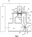
- the figure shows a schematic representation of an exhaust gas recirculation system according to the invention in a first operating position.
- the exhaust gas recirculation system shown comprises an exhaust gas duct 10, which leads to an outlet 12 and into which exhaust gas from an internal combustion engine 14 is introduced. Furthermore, the Exhaust gas recirculation system has an inlet channel 16 through which air is sucked in from the environment and which is usually connected to the internal combustion engine 14 via a compressor.
- the exhaust duct 10 is connected to the inlet duct 16 via an exhaust gas recirculation duct 18, via which exhaust gas from the exhaust duct 10 can be guided back to the inlet duct 16.
- a heat exchanger 20 is arranged in the exhaust gas recirculation duct 18, which has two strands 24, 26 separated from one another by a partition 22.
- the partition 22 ends in front of the end of the heat exchanger 20 pointing towards the inlet duct 16, so that exhaust gas can either flow in a U-shape from the first strand 24 into the second strand 26, or the exhaust gas flows from both strands 24, 26 to an exhaust gas recirculation valve 28 arranged downstream at an outlet 27 of the heat exchanger 20.
- This exhaust gas recirculation valve 28 is designed as a valve unit 30 with a bypass valve 32, via which a flow cross-section of a bypass line 34 can be regulated, which branches off from the exhaust gas channel 10 upstream of the heat exchanger 20 and opens into the exhaust gas recirculation channel 18 downstream of the heat exchanger 20, bypassing the heat exchanger 20.
- the valve unit has an actuator 36, which actuates a valve rod 38, on which the two control elements 40, 42 of the exhaust gas recirculation valve 28 and the bypass valve 32 are arranged so as to be displaceable.
- the two control elements 40, 42 are each braced in the direction of a shoulder (not shown) on the valve rod 38 via a spring element 44 arranged between the control elements 40, 42.
- Both control elements 40, 42 can be placed on a valve seat 46, 48, so that when the actuator 36 is actuated in the first direction, the flow cross-section of the exhaust gas recirculation channel 18 at the outlet 27 of the heat exchanger 20 can be regulated via the exhaust gas recirculation valve 28, while the bypass line 34 is closed by the bypass valve 32 and when the actuator 36 is actuated in the opposite direction, the Exhaust gas recirculation channel 18 is closed by the control element 40 of the exhaust gas recirculation valve 28, while the flow cross-section of the bypass line 34 is regulated by the control element 42 of the bypass valve 32.
- a flap valve 50 designed as a butterfly valve is arranged in the exhaust duct 10, which is adjustable in both directions of rotation and whose shaft 52, viewed in the direction of the extension of the exhaust duct 10, is arranged between the partition wall 22 and a downstream wall 54 of the heat exchanger 20.
- This flap valve 50 is continuously adjustable by means of an actuator 51 via the shaft 52 and can in particular be rotated into a first position in which it extends along the central axis of the exhaust duct 10 and thus largely exposes it, rotated into a second position in which it closes the exhaust duct 10 downstream of the two strands 24, 26 in the flow direction and accordingly rests against the downstream wall 54 of the heat exchanger 20 and rotated into a third position in which the exhaust duct 10 is closed in the area between the two strands 24, 26, the flap valve 50 is therefore arranged directly opposite the partition wall 22 of the heat exchanger 20 and rests with the opposite side against the wall of the exhaust duct 10. Furthermore, any intermediate positions can be reached.
- the flap valve 50 can be turned into the third position, in which the flap valve 50 closes the exhaust duct 10 between the two branches 24, 26, while the exhaust gas recirculation valve 28 and the bypass valve 32 are in the closed position, so that the exhaust gas from the exhaust duct 10 initially flows into the first branch 24 of the heat exchanger 20 and is diverted by 180° at the end of the partition wall 22 and flows through the second branch 26 in the opposite direction in order to flow back into the exhaust duct 10 behind the flap valve 50.
- a rapid heating of the coolant of the heat exchanger 20 is achieved, so that the energy of the exhaust gas can be used for heat recovery.
- the flap valve 50 can be turned into a position that closes or at least throttles the exhaust gas channel 10 downstream of the heat exchanger 20, so that the counterpressure in the exhaust gas channel 10 is increased and thus the amount of exhaust gas recirculated is increased.
- thermal management with heat recovery can be carried out by allowing the heat exchanger 20 to flow through at cold ambient temperatures by turning the flap valve 50 to a position that partially throttles the exhaust duct 10, so that the first branch 24 and then the second branch 26 of the heat exchanger 20 flow through first.
- the heat of the exhaust gas can be absorbed and used by the coolant and cooling of the heat exchanger 20 with the resulting formation of condensate in the heat exchanger 20 can be prevented.
- the flap valve 50 can be turned to a position that closes the exhaust duct 10 between the two branches 24, 26 and the exhaust gas recirculation valve 28 can be regulated in order to recover heat and to return cooled exhaust gas to the internal combustion engine 14.
- By opening the Bypass valve 32 and closing the exhaust gas recirculation valve 28 hot exhaust gas can also be recirculated and heat can be recovered at the same time.
- cooled exhaust gas can also be returned to the internal combustion engine 14 in this phase by opening the flap valve 50 and the exhaust gas recirculation valve 28 so that the exhaust gas in the heat exchanger 20 flows in parallel through the first branch 24 and the second branch 26.
- the flap valve 50 can also be turned on so that the exhaust gas channel 10 downstream of the heat exchanger 20 is throttled or closed. In this case, an increased amount of exhaust gas is fed in parallel through the two branches 24, 26 back to the internal combustion engine 14. The heat dissipated to the coolant can still be used.
- the exhaust gas recirculation system according to the invention described is suitable for the low-pressure range, whereby high recirculated exhaust gas quantities can be made available and at the same time a high efficiency is achieved in relation to the recovered thermal energy.
- the recovered thermal energy, the exhaust gas temperature and the exhaust gas quantity can be controlled with a minimal number of components used. Condensates that can lead to sooting of the heat exchanger or damage to a subsequent compressor are minimized.
Landscapes
- Engineering & Computer Science (AREA)
- Chemical & Material Sciences (AREA)
- Combustion & Propulsion (AREA)
- Mechanical Engineering (AREA)
- General Engineering & Computer Science (AREA)
- Exhaust-Gas Circulating Devices (AREA)
Description
- Die vorliegende Erfindung betrifft ein Abgasrückführsystem für eine Verbrennungskraftmaschine mit einem Abgaskanal der Verbrennungskraftmaschine, einem Einlasskanal der Verbrennungskraftmaschine, einem Abgasrückführkanal, der vom Abgaskanal abzweigt und in den Einlasskanal mündet, einem Wärmetauscher, der im Abgasrückführkanal angeordnet ist, und zwei voneinander getrennte Stränge aufweist, einem Abgasrückführventil, welches am Auslass des Wärmetauschers angeordnet ist, einem Klappenventil, welches derart im Abgaskanal angeordnet ist, dass das Klappenventil in einer ersten Stellung den Abgaskanal freigibt, in einer zweiten Stellung den Abgaskanal in Strömungsrichtung stromabwärts der beiden Stränge verschließt, in einer dritten Stellung den Abgaskanal im Bereich zwischen beiden Strängen verschließt und in einer vierten Stellung den Abgaskanal drosselt sowie ein Verfahren zur Regelung eines derartigen Abgasrückfü hrsystems.
- Abgasrückführsysteme sind bekannt und dienen zur Reduzierung der Schadstoffanteile in Verbrennungsmotoren. Es wird dabei unterschieden zwischen einer zylinderinternen Abgasrückführung, einer externen Hochdruckabgasrückführung und einer Niederdruckabgasrückführung. Bei der Niederdruckabgasrückführung ist es zur Erzielung ausreichend hoher Abgasrückführraten notwendig, eine Abgasklappe zur Erhöhung des Strömungswiderstandes in der Abgasleitung vorzusehen. Auch ist es bekannt, im Abgasrückführkanal umgehbare Wärmetauscher vorzusehen, durch die die Temperatur des zurückgeführten Abgases herabgesetzt werden kann, wenn dies zur Verringerung der Verbrennungstemperatur im Motor erforderlich ist.
- Zusätzlich zu diesen Zwecken der Abgasrückführung wird das heiße Abgas in den letzten Jahren zur Wärmegewinnung im Kraftfahrzeug genutzt. Anstatt das warme Abgas unmittelbar über die Abgasleitung aus dem Fahrzeug abzuleiten, wird dessen thermische Energie genutzt, um beispielsweise die Verbrennungskraftmaschine schneller aufzuheizen, die Fahrerkabine schneller zu erwärmen oder Reibungsverluste durch Erhitzen des Schmiermittelsystems zu reduzieren. Die thermische Energie wird dabei über den Wärmetauscher des Abgasrückführsystems dem Abgas entzogen.
- Ein Abgasrückführsystem nach dem Stand der Technik ist beispielsweise aus der
WO 2014/136024 A1 bekannt. Es weist einen U-förmigen Wärmetauscher auf, welcher mit einem Abgaskanal und stromabwärts des Wärmetauschers über ein Abgasrückführventil mit einem Einlasskanal, über den Verbrennungsluft zu der Verbrennungskraftmaschine leitbar ist, verbunden ist. In dem Abgaskanal ist ein Klappenventil angeordnet, welches zwischen einer ersten Stellung, bei welcher der Abgaskanal vollständig geöffnet und eine Mündung des Wärmetauschers vollständig verschlossen ist und einer zweiten Stellung, bei welcher der Abgaskanal im Bereich des Wärmetauschers vollständig verschlossen und ein in Strömungsrichtung vorgelagerter Strang des U-förmigen Wärmetauschers vollständig geöffnet ist, so dass der Abgasstrom in diesen Strang des Wärmetauschers geleitet wird, verstellbar ist. Dieses Abgasrückführsystem hat den Nachteil, dass ein ausreichend hohes Strömungsgefälle im Abgasrückführkanal anliegen muss, damit der Wärmetauscher mit einer ausreichenden Abgasmenge durchströmt wird. Dadurch ist dieses Abgasrückführsystem nicht für den Niederdruckbetrieb geeignet, da der Widerstand im Abgasrückführkanal immer höher ist als im Abgaskanal. Entsprechend wird keine ausreichende Regelbarkeit des zurückgeführten Abgasstromes erreicht, insbesondere in Phasen mit hohen Abgasrückführraten. Die gesetzlich vorgeschriebenen Emissionswerte sind entsprechend mit einem derartigen Abgasrückführsystem, insbesondere im Niederdruckbereich, nicht erreichbar. - Daher wurde in der
DE 10 2017 111 101 A1 ein Abgasrückführsystem vorgeschlagen, bei dem die im Abgasauslasskanal angeordnete Klappe den Wärmetauscher stromabwärts beider Stränge des Wärmetauschers verschließen kann oder den Abgaskanal zwischen den beiden Strängen verschließt. Entsprechend kann Wärme aus dem Abgas aufgenommen werden und zur Wärmerückgewinnung genutzt werden oder Abgas in ausreichender Menge zurückgeführt werden, indem der Strömungswiderstand in der Abgasauslassleitung erhöht wird. - Des Weiteren ist aus der
EP 0 994 247 A2 ein Abgasrückführsystem bekannt, bei dem von einem Abgaskanal eine Abgasrückführleitung abzweigt, die sich im Folgenden in zwei Stränge gabelt. Im ersten Strang hinter der Gabelung ist ein Wärmetauscher angeordnet, der über eine durch den zweiten Strang ausgebildete Bypassleitung umgangen werden kann. Am Ende der Bypassleitung ist ein Hubventil angeordnet, welches über einen gemeinsamen Aktor mit einem Hubventil verbunden ist, welches stromabwärts des Wärmetauschers angeordnet ist. Durch Betätigung des Aktors wird entweder der Bypasskanal oder der Kühlkanal geöffnet. Im Ruhezustand sind beide Stränge geschlossen. - Nachteilig an diesem Abgasrückführsystem ist es jedoch, dass eine Temperaturregelung des zurückgeführten Abgases nicht möglich ist. Entsprechend ist eine Kondensatbildung im Einlasskanal, die zu Beschädigungen eines nachgeordneten Verdichters führen kann, ebenso wenig auszuschließen, wie eine zu lange Warmlaufphase der Verbrennungskraftmaschine.
- Die Aufgabe der vorliegenden Erfindung liegt somit darin, ein Abgasrückführsystem für eine Verbrennungskraftmaschine sowie ein Verfahren zur Regelung eines derartigen Abgasrückführsystems zu schaffen, welche für den Niederdruckbetrieb geeignet ist und eine Temperaturregelung des Abgases ermöglicht, ohne dass der Aufbau des Systems zu aufwendig wird. Schäden an einem nachgeschalteten Verdichter sollen ebenso vermieden werden, wie zu lange Warmlaufzeiten oder eine erhöhte Versottung des Wärmetauschers durch anfallendes Kondensat.
- Diese Aufgabe wird durch ein Abgasrückführsystem für eine Verbrennungskraftmaschine mit den Merkmalen des Anspruchs 1 sowie durch ein Verfahren zur Regelung eines derartigen Abgasrückführsystems mit den Merkmalen des Anspruchs 11 gelöst.
- Das erfindungsgemäße Abgasrückführsystem weist einen Wärmetauscher mit zwei baulich voneinander getrennten Strängen auf, welche entweder U-förmig oder parallel durchströmbar sind. Die beiden Stränge sind derart ausgestaltet, dass eine gegenseitige Beeinflussung der Strömungen in den Strängen vermieden wird. Am zum Einlasskanal weisenden Ende beider Stränge sind diese über einen Sammler miteinander verbunden, so dass in Abhängigkeit von der Klappenstellung des Abgasrückführventils entweder das Abgas aus beiden Strängen über den Sammler in den Abgasrückführkanal geleitet wird, oder das Abgas von dem in Abgasrichtung im Abgaskanal vorgelagerten ersten Strang über den Sammler U-förmig in den zweiten Strang geleitet wird.
- Das Abgasrückführsystem weist ein Klappenventil auf, welches derart im Abgaskanal angeordnet ist, dass das Klappenventil in einer ersten Stellung den Abgaskanal freigibt, in einer zweiten Stellung den Abgaskanal in Strömungsrichtung stromabwärts der beiden Stränge verschließt, so dass der Abgasstrom beide Stränge in Richtung vom Abgaskanal zum Einlasskanal durchströmt, in einer dritten Stellung das Klappenventil den Abgaskanal im Bereich zwischen beiden Strängen verschließt, so dass der Abgasstrom durch den in Abgasrichtung vorgelagerten ersten Strang geleitet wird, und der zweite Strang in Abhängigkeit der Stellung des Abgasrückführventils in entgegengesetzter Richtung durchströmt wird, woraufhin das Abgas aus dem zweiten Strang stromabwärts des Klappenventils wieder in den Abgaskanal strömt, und in einer vierten Stellung den Abgaskanal drosselt, also lediglich teilweise verschließt.
- In der ersten Stellung hat das Klappenventil somit einen minimalen Strömungswiderstand im Abgaskanal, so dass die Strömung im Abgaskanal durch das Klappenventil kaum gestört wird. In der zweiten Stellung hingegen wird eine vollständige Durchströmung des Abgaskanals vom Klappenventil an stromabwärts der beiden Stränge unterbunden. Das Abgas wird bei geöffnetem AGR-Ventil dadurch in beide Stränge des Wärmetauschers umgeleitet, so dass die gesamte Abgasmenge auf zwei Stränge verteilt wird und dadurch der maximale Wärmetauscherquerschnitt ausgenutzt wird. Dadurch wird der Anteil der zurückgewonnenen thermischen Energie erhöht, da die Temperaturdifferenz zwischen dem Kühlmittel und dem Abgas größer ist als bei einer U-förmigen Durchströmung des Kühlers.
- In der dritten Stellung wird eine Durchströmung des Abgaskanals ab der baulichen Trennung zwischen den Strängen unterbunden. Das Abgas wird dadurch durch den in Strömungsrichtung vorgelagerten Strang geleitet. In Abhängigkeit der Klappenstellung des AGR-Ventils wird dadurch bei geöffnetem Abgasrückführventil ein Teil des Abgases zur Verbrennungskraftmaschine zurückgeführt, während der Rest durch den zweiten Strang zum Abgaskanal gelangt. Bei geschlossenem Abgasrückführventil strömt das gesamte Abgas U-förmig durch den Kühler, so dass Energie aus dem Abgasstrom entnommen werden kann.
- Erfindungsgemäß ist der Wärmetauscher über eine Bypassleitung umgehbar, deren Durchströmungsquerschnitt mittels eines Bypassventils regelbar ist und welche stromaufwärts des Klappenventils vom Abgaskanal abzweigt. Somit kann auch heißes Abgas direkt zur Verbrennungskraftmaschine gefördert werden. Entsprechend können die Warmlaufzeiten der Verbrennungskraftmaschine verringert werden und die Abgastemperatur an den jeweiligen Betriebszustand angepasst werden. Insbesondere kann die Kondensationsneigung des Wassers im Abgas beim Einströmen in die Ansaugluft verringert werden, indem das Abgas mit höheren Temperaturen zum Einlasskanal gelangt, wodurch höhere Mischtemperaturen erreicht werden. Auch wird die Versottung des Wärmetauschers durch Verringerung der Kondensation reduziert.
- Bezüglich des erfindungsgemäßen Verfahrens wird die Aufgabe dadurch gelöst, dass nach dem Kaltstart der Verbrennungskraftmaschine das Klappenventil den Abgaskanal zwischen den beiden Strängen des Wärmetauschers verschließt, das Bypassventil die Bypassleitung verschließt und das Abgasrückführventil den Auslass des Wärmetauschers verschließt, sodass der Wärmetauscher durchströmt wird und entsprechend aufheizen kann, wobei die thermische Energie zur Rückgewinnung, beispielsweise zur Aufheizung des Fahrgastraumes genutzt werden kann.
- Anschließend gibt in der Warmlaufphase der Verbrennungskraftmaschine bei Volllast das Klappenventil den Abgaskanal frei, das Bypassventil die Bypassleitung frei und das Abgasrückführventil verschließt den Auslass des Wärmetauschers, wodurch eine schnelle Aufheizung der Verbrennungskraftmaschine zur Verringerung der Schadstoffe erreicht wird.
- Bei Teillast in der Warmlaufphase der Verbrennungskraftmaschine verschließt das Klappenventil den Abgaskanal stromabwärts beider Stränge des Wärmetauschers, das Bypassventil gibt die Bypassleitung frei und das Abgasrückführventil verschließt den Auslass des Wärmetauschers, wodurch die zurückgeführte Abgasmenge erhöht wird.
- Nach der Warmlaufphase der Verbrennungskraftmaschine gibt bei Volllast das Klappenventil den Abgaskanal frei, das Bypassventil verschließt die Bypassleitung und das Abgasrückführventil gibt den Auslass des Wärmetauschers frei, sodass das Abgas gekühlt zurückgeführt wird, wodurch ebenfalls die Schadstoffemissionen verringert werden.
- Bei Teillast wird die zurückgeführte Abgasmenge erhöht, indem nach der Warmlaufphase der Verbrennungskraftmaschine das Klappenventil den Abgaskanal stromabwärts beider Stränge des Wärmetauschers zumindest drosselt, das Bypassventil die Bypassleitung verschließt und das Abgasrückführventil den Auslass des Wärmetauschers freigibt. So kann mit sehr geringem baulichem Aufwand eine vollständige Regelung des zurückgeführten Abgases zur Erreichung optimaler Temperaturen und Mengen hergestellt werden, sodass die Warmlaufphase verkürzt werden kann und eine Kondensation vor dem Verdichter im Einlasskanal verringert werden kann.
- Vorzugsweise weist das Bypassventil ein Regelorgan auf, welches mittels eines Aktors bewegbar ist. Somit ist eine genaue Verstellung des Bypassventils zur Regelung der über die Bypassleitung zurückgeführten Abgasmenge möglich.
- In einer besonders bevorzugten Ausbildung der Erfindung weisen das Abgasrückführventil und das Bypassventil einen gemeinsamen Aktor auf, sodass auf einen separaten Aktor verzichtet werden kann. Hierfür können unterschiedliche Regelorgane verwendet werden, die eine abhängige oder teilweise abhängige oder eine unabhängige Regelung des Öffnungsquerschnitts der beiden Ventile ermöglicht. Es ist dabei lediglich erforderlich, dass ein Öffnungsquerschnitt des Abgasrückführventils bei geschlossenem Bypassventil und des Bypassventils bei geschlossenem Abgasrückführventil freigegeben werden kann.
- In einer hierzu weiterführenden Ausführungsform weisen das Abgasrückführventil und das Bypassventil jeweils ein Regelorgan auf, welches auf einer Ventilstange angeordnet ist, die mittels des Aktors bewegbar ist. Somit kann ein einfacher translatorisch arbeitender Aktor vorgesehen werden, der elektromotorisch mit nachgeschaltetem Getriebe oder elektromagnetisch oder pneumatisch angetrieben wird.
- Ein besonders einfacher Aufbau eines derartigen Ventils ergibt sich, wenn die beiden Regelorgane verschieblich und jeweils gegen einen Anschlag vorgespannt auf einer gemeinsamen Ventilstange angeordnet sind und in ihren den jeweiligen Durchströmungsquerschnitt verschließenden Positionen auf einem Ventilsitz aufliegen. Bei einer derartigen Ausführung kann der jeweilige Öffnungsquerschnitt bei geschlossenem zweitem Ventil vollständig geregelt werden. Entsprechend ist jedes der beiden Regelorgane zur Regelung des jeweiligen Durchströmungsquerschnitts bewegbar, während das jeweils andere Regelorgan auf dem Ventilsitz aufliegt.
- Vorzugsweise ist das Klappenventil stufenlos zwischen den vier Stellungen und in beide Drehrichtungen verstellbar, so dass schnell zwischen den Stellungen hin- und hergeschaltet werden kann. Durch die beiden Drehrichtungen kann auch jeweils der kürzeste Verstellweg gewählt werden und die Klappe so konstruiert werden, dass das Ventil in zwei Stellungen gegen einen festen Anschlag anliegt.
- In einer vorteilhaften Ausgestaltung ist die Drehachse des Klappenventils zwischen einer Verlängerung der baulichen Trennung der Stränge und in Strömungsrichtung des Abgaskanals betrachtet einer Verlängerung einer stromabwärtigen Wand des Wärmetauschers angeordnet. Dies vereinfacht den Aufbau des Klappenventils mit seinem umgebenden Gehäuse und ermöglicht eine vollständige Unterbringung des Klappenventils im Abgaskanal.
- In einer besonders einfachen Ausführung des Wärmetauschers sind die beiden Stränge durch eine Trennwand voneinander getrennt. Eine solche Trennwand ist einfach herstellbar und kann als Anschlag für die Klappe dienen.
- Vorzugsweise ist ein von der Drehachse entferntes Klappenende in der zweiten und dritten Stellung entweder unmittelbar gegenüberliegend zur stromabwärtigen Wand des Wärmetauschers oder Trennwand angeordnet oder liegt gegen die stromabwärtige Wand des Wärmetauschers oder die Trennwand an, wodurch jeweils ein dichter Verschluss des Abgaskanals in den beiden Stellungen hergestellt werden kann.
- In einer Weiterführung des erfindungsgemäßen Verfahrens drosselt in der aufgeheizten Phase der Verbrennungskraftmaschine bei kalten Umgebungstemperaturen das Klappenventil den Abgaskanal, während das Bypassventil die Bypassleitung verschließt und das Abgasrückführventil den Auslass des Wärmetauschers verschließt, so dass Abgas zunächst durch den ersten Strang und anschließend in umgekehrter Richtung durch den zweiten Strang des Wärmetauschers strömt. Auf diese Weise wird eine Wärmerückgewinnung weiter ermöglicht und eine erhöhte Kondensatbildung mit folgender Versottung durch ein Abkühlen des Wärmetauschers zuverlässig verhindert.
- Des Weiteren ist es vorteilhaft, wenn bei Ausfall des Aktors des Bypassventils und des Abgasrückführventils das Bypassventil die Bypassleitung verschließt und das Abgasrückführventil den Auslass des Wärmetauschers verschließt, da auf diese Weise ein Betrieb der Verbrennungskraftmaschine weiterhin möglich ist. Bei Ausfall des Aktors des Klappenventils gibt entsprechend das Klappenventil den Abgaskanal frei, so dass die Verbrennungskraftmaschine weiter betrieben werden kann.
- Vorzugsweise verschließt das Klappenventil zur Abgaswärmerückgewinnung den Abgaskanal zwischen den Strängen, während die zurückgeführte Abgasmenge durch die Stellung des Bypassventils und des Abgasrückführventils geregelt wird. So wird auch in Betriebszuständen, in denen eine Abgasrückführung von kaltem oder heißem Abgas gewünscht ist, eine Wärmerückgewinnung über den Wärmetauscher ermöglicht und ein Auskühlen des Wärmetauschers mit anschließender, erhöhter Kondensatbildung verhindert.
- Es wird somit ein Abgasrückführsystem sowie ein Verfahren zur Regelung dieses Abgasrückführsystems für eine Verbrennungskraftmaschine geschaffen, welche eine Temperatur- und Mengenregelung des Abgases im Abgaskanal und im Abgasrückführkanal ermöglicht, wodurch Wärme zurückgewonnen werden kann, Kondensation im Wärmetauscher und im Einlasskanal vor einem nachfolgenden Verdichter verhindert werden kann. Dennoch bleibt der Bauteileaufwand vergleichbar gering.
- Weitere Einzelheiten und Vorteile der vorliegenden Erfindung ergeben sich aus der nachfolgenden Beschreibung der Ausführungsbeispiele in Verbindung mit den Zeichnungen.
- Die Figur zeigt eine schematische Darstellung eines erfindungsgemäßen Abgasrückführsystems in einer ersten Betriebsstellung.
- Das dargestellte Abgasrückführsystem umfasst einen Abgaskanal 10, welcher zu einem Auslass 12 führt und in den Abgas aus einer Verbrennungskraftmaschine 14 eingeleitet wird. Des Weiteren weist das Abgasrückführsystem einen Einlasskanal 16 auf, über welchen Luft aus der Umgebung angesaugt wird und der üblicherweise über einen Verdichter mit der Verbrennungskraftmaschine 14 verbunden ist.
- Der Abgaskanal 10 ist mit dem Einlasskanal 16 über einen Abgasrückführkanal 18 verbunden, über den Abgas aus dem Abgaskanal 10 zurück zum Einlasskanal 16 geführt werden kann. In dem Abgasrückführkanal 18 ist ein Wärmetauscher 20 angeordnet, der zwei voneinander durch eine Trennwand 22 getrennte Stränge 24, 26 aufweist. Die Trennwand 22 endet vor dem zum Einlasskanal 16 weisenden Ende des Wärmetauschers 20, so dass Abgas entweder U-förmig vom ersten Strang 24 in den zweiten Strang 26 strömen kann oder aus beiden Strängen 24, 26 das Abgas zu einem stromabwärts an einem Auslass 27 des Wärmetauschers 20 angeordneten Abgasrückführventil 28 strömt.
- Dieses Abgasrückführventil 28 ist als Ventileinheit 30 mit einem Bypassventil 32 ausgebildet, über welches ein Durchströmungsquerschnitt einer Bypassleitung 34 regelbar ist, die stromaufwärts des Wärmetauschers 20 vom Abgaskanal 10 abzweigt und unter Umgehung des Wärmetauschers 20 stromabwärts des Wärmetauschers 20 in den Abgasrückführkanal 18 mündet. Die Ventileinheit weist einen Aktor 36 auf, der eine Ventilstange 38 betätigt, auf der die beiden Regelorgane 40, 42 des Abgasrückführventils 28 beziehungsweise des Bypassventils 32 verschieblich angeordnet sind. Die beiden Regelorgane 40, 42 sind über ein zwischen den Regelorganen 40, 42 angeordnetes Federelement 44 jeweils in Richtung eines nicht dargestellten Absatzes auf der Ventilstange 38 verspannt. Beide Regelorgane 40, 42 sind auf einen Ventilsitz 46, 48 aufsetzbar, so dass bei Betätigung des Aktors 36 in die erste Richtung der Durchströmungsquerschnitt des Abgasrückführkanals 18 am Auslass 27 des Wärmetauschers 20 über das Abgasrückführventil 28 regelbar ist, während die Bypassleitung 34 durch das Bypassventil 32 verschlossen ist und bei Betätigung des Aktors 36 in die entgegengesetzte Richtung der Abgasrückführkanal 18 durch das Regelorgan 40 des Abgasrückführventils 28 verschlossen ist, während der Durchströmungsquerschnitt der Bypassleitung 34 durch das Regelorgan 42 des Bypassventils 32 geregelt wird.
- Im Abgaskanal 10 ist ein als Schmetterlingsventil ausgebildetes Klappenventil 50 angeordnet, welches in beide Drehrichtungen verstellbar ist und dessen Welle 52 in Richtung der Erstreckung des Abgaskanals 10 betrachtet zwischen der Trennwand 22 und einer stromabwärtigen Wand 54 des Wärmetauschers 20 angeordnet ist. Dieses Klappenventil 50 ist mittels eines Aktors 51 über die Welle 52 kontinuierlich verstellbar und kann insbesondere in eine erste Stellung gedreht werden, in der es sich entlang der Mittelachse des Abgaskanals 10 erstreckt und somit diesen weitestgehend freigibt, in eine zweite Stellung gedreht werden, in der es den Abgaskanal 10 in Strömungsrichtung stromabwärts der beiden Stränge 24, 26 verschließt und entsprechend gegen die stromabwärtige Wand 54 des Wärmetauschers 20 anliegt und in eine dritte Stellung gedreht werden, in der der Abgaskanal 10 im Bereich zwischen beiden Strängen 24, 26 verschlossen wird, das Klappenventil 50 also unmittelbar gegenüberliegend zur Trennwand 22 des Wärmtauschers 20 angeordnet ist und mit der gegenüberliegenden Seite gegen die Wand des Abgaskanals 10 anliegt. Des Weiteren sind beliebige Zwischenstellungen anfahrbar.
- Mit diesem Abgassystem können nun für verschiedene Betriebszustände optimale Temperaturen und Mengen eingestellt werden und eine Wärmerückgewinnung aus dem Abgas optimiert werden.
- So kann unmittelbar nach dem Kaltstart das Klappenventil 50 in die dritte Stellung gedreht werden, in der das Klappenventil 50 den Abgaskanal 10 zwischen den beiden Strängen 24, 26 verschließt, während das Abgasrückführventil 28 und das Bypassventil 32 sich in der geschlossenen Position befinden, sodass das Abgas aus dem Abgaskanal 10 zunächst in den ersten Strang 24 des Wärmetauschers 20 strömt und am Ende der Trennwand 22 um 180° umgeleitet wird und den zweiten Strang 26 in entgegengesetzter Richtung durchströmt, um hinter dem Klappenventil 50 wieder in den Abgaskanal 10 zu strömen. Auf diese Weise wird ein schnelles Aufheizen des Kühlmittels des Wärmetauschers 20 erreicht, so dass die Energie des Abgases zur Wärmerückgewinnung genutzt werden kann.
- In der Warmlaufphase kann durch Öffnen des Bypassventils 32 und Schließen des Abgasrückführventils 28 Abgas mit einer hohen Temperatur zur Verbrennung zurückgeführt werden, wodurch eine schnelle Aufheizung der Verbrennungskraftmaschine 14 ermöglicht wird. Ist dabei eine hohe Abgasrückführrate gewünscht kann das Klappenventil 50 in eine den Abgaskanal 10 stromabwärts des Wärmetauschers 20 verschließende oder zumindest drosselnde Stellung gedreht werden, so dass der Gegendruck im Abgaskanal 10 erhöht wird und somit die zurückgeführte Abgasmenge erhöht wird.
- Nach der Warmlaufphase kann ein Thermomanagement mit Wärmerückgewinnung erfolgen, indem der Wärmetauscher 20 bei kalten Umgebungstemperaturen durchströmt wird, indem das Klappenventil 50 auf eine den Abgaskanal 10 teilweise drosselnde Stellung gedreht wird, so dass zunächst der erste Strang 24 und anschließend der zweite Strang 26 des Wärmetauschers 20 durchströmt wird. Dabei kann sowohl die Wärme des Abgases durch das Kühlmittel aufgenommen und genutzt werden als auch ein Auskühlen des Wärmetauschers 20 mit daraus folgender Kondensatbildung im Wärmetauscher 20 verhindert werden. Bei normalen Umgebungstemperaturen kann das Klappenventil 50 in eine den Abgaskanal 10 zwischen den beiden Strängen 24, 26 verschließende Stellung gedreht werden und das Abgasrückführventil 28 geregelt werden, um einerseits Wärme zurückzugewinnen als auch Abgas gekühlt zur Verbrennungskraftmaschine 14 zurückzuführen. Durch Öffnen des Bypassventils 32 und Schließen des Abgasrückführventils 28 kann auch heißes Abgas zurückgeführt werden und gleichzeitig Wärme zurückgewonnen werden.
- Zusätzlich kann in dieser Phase auch Abgas gekühlt zur Verbrennungskraftmaschine 14 zurückgeführt werden, indem das Klappenventil 50 geöffnet wird und das Abgasrückführventil 28 geöffnet wird, so dass das Abgas im Wärmetauscher 20 parallel durch den ersten Strang 24 und den zweiten Strang 26 strömt. Zur Erhöhung der zurückgeführten Abgasmenge kann das Klappenventil 50 auch angestellt werden, so dass der Abgaskanal 10 stromabwärts des Wärmetauschers 20 gedrosselt beziehungsweise geschlossen wird. In diesem Fall wird eine erhöhte Abgasmenge parallel durch die beiden Stränge 24, 26 zurück zur Verbrennungskraftmaschine 14 geführt. Die an das Kühlmittel abgeführte Wärme kann weiterhin genutzt werden.
- Zusätzlich wird bei einem derartigen kombinierten Abgasrückführventil 28 und Bypassventil 32, bei dem zwischen den beiden Regelorganen 40, 42 das Federelement 44 angeordnet ist, über die die beiden Regelorgane 40, 42 gegen ihre Ventilsitze 46, 48 gedrückt werden, bei Ausfall des Aktors 36 eine Sicherheitsstellung angefahren, in der eine Abgasrückführung unterbrochen wird. Das Klappenventil 50 wird in diesem Betriebszustand geöffnet und weist ebenfalls eine fail-safe Stellung auf, so dass das Klappenventil 50 bei Ausfall des Aktors 51 in seine den Abgaskanal 10 öffnende Stellung gedreht wird.
- Das beschriebene erfindungsgemäße Abgasrückführsystem ist für den Niederdruckbereich geeignet, wobei hohe zurückgeführte Abgasmengen zur Verfügung gestellt werden können und gleichzeitig ein hoher Wirkungsgrad in Bezug auf die zurückgewonnene thermische Energie erreicht wird. Darüber hinaus ist eine Regelbarkeit der zurückgewonnenen thermischen Energie, der Abgastemperatur und der Abgasmenge mit einer minimalen Anzahl verwendeter Bauteile möglich. Anfallende Kondensate, die zu einer Versottung des Wärmetauschers oder zu Schäden an einem nachfolgenden Verdichter führen, werden minimiert.
- Es sollte deutlich sein, dass der Schutzbereich nicht auf das beschriebene Ausführungsbeispiel eines Abgasrückführsystems beschränkt ist, sondern verschiedene Modifikationen und konstruktive Änderungen denkbar sind. Beispielsweise sind andere Ausgestaltungen des Klappenventils möglich. Auch müssen die Stränge nicht durch eine einzige Trennwand voneinander getrennt sein, sondern können durch unabhängig voneinander angeordnete Stränge ausgebildet sein. Des Weiteren sind unterschiedliche Ausführungen des kombinierten Abgasrückführ- und Bypassventils denkbar. Dabei ist beispielsweise auch eine Anordnung der Regelorgane auf zwei Ventilstangen denkbar, die nebeneinander angeordnet sind und über einen gemeinsamen Aktor betätigt werden.
Claims (15)
- Abgasrückführsystem für eine Verbrennungskraftmaschine mit- einem Abgaskanal (10) der Verbrennungskraftmaschine (14),- einem Einlasskanal (16) der Verbrennungskraftmaschine (14),- einem Abgasrückführkanal (18), der vom Abgaskanal (10) abzweigt und in den Einlasskanal (16) mündet,- einem Wärmetauscher (20), der im Abgasrückführkanal (18) angeordnet ist, und zwei voneinander getrennte Stränge (24, 26) aufweist,- einem Abgasrückführventil (28), welches an einem Auslass (27) des Wärmetauschers (20) angeordnet ist,- einem Klappenventil (50), welches derart im Abgaskanal (10) angeordnet ist, dass das Klappenventil (50) in einer ersten Stellung den Abgaskanal (10) freigibt, in einer zweiten Stellung den Abgaskanal (10) in Strömungsrichtung stromabwärts der beiden Stränge (24, 26) verschließt, in einer dritten Stellung den Abgaskanal (10) im Bereich zwischen beiden Strängen (24, 26) verschließt und in einer vierten Stellung den Abgaskanal (10) drosselt,dadurch gekennzeichnet, dass
der Wärmetauscher (20) über eine Bypassleitung (34) umgehbar ist, deren Durchströmungsquerschnitt mittels eines Bypassventils (32) regelbar ist und welche stromaufwärts des Klappenventils (50) vom Abgaskanal (10) abzweigt. - Abgasrückführsystem für eine Verbrennungskraftmaschine nach Anspruch 1,
dadurch gekennzeichnet, dass
das Bypassventil (32) ein Regelorgan (42) aufweist, welches mittels eines Aktors (36) bewegbar ist. - Abgasrückführsystem für eine Verbrennungskraftmaschine nach Anspruch 2,
dadurch gekennzeichnet, dass
das Abgasrückführventil (28) und das Bypassventil (32) einen gemeinsamen Aktor (36) aufweisen. - Abgasrückführsystem nach Anspruch 3,
dadurch gekennzeichnet, dass
das Abgasrückführventil (28) und das Bypassventil (32) jeweils ein Regelorgan (40, 42) aufweisen, welches auf einer Ventilstange (38) angeordnet ist, die mittels des Aktors (36) bewegbar ist. - Abgasrückführsystem für eine Verbrennungskraftmaschine nach Anspruch 4,
dadurch gekennzeichnet, dass
die beiden Regelorgane (40, 42) verschieblich und jeweils gegen einen Anschlag vorgespannt auf einer gemeinsamen Ventilstange (38) angeordnet sind und in ihren den jeweiligen Durchströmungsquerschnitt verschließenden Positionen auf einem Ventilsitz (46, 48) aufliegen. - Abgasrückführsystem für eine Verbrennungskraftmaschine nach Anspruch 4 oder 5,
dadurch gekennzeichnet, dass
jedes der beiden Regelorgane (40, 42) zur Regelung des jeweiligen Durchströmungsquerschnitts bewegbar ist, während das jeweils andere Regelorgan (40, 42) auf dem Ventilsitz (46, 48) aufliegt. - Abgasrückführsystem für eine Verbrennungskraftmaschine nach einem der vorherigen Ansprüche,
dadurch gekennzeichnet, dass
das Klappenventil (50) mittels eines Aktors (51) stufenlos zwischen den vier Stellungen und in beide Drehrichtungen verstellbar ist. - Abgasrückführsystem für eine Verbrennungskraftmaschine nach einem der vorherigen Ansprüche,
dadurch gekennzeichnet, dass
die Drehachse des Klappenventils (50) zwischen einer Verlängerung der baulichen Trennung der Stränge (24, 26) und in Strömungsrichtung des Abgaskanals (10) betrachtet einer Verlängerung einer stromabwärtigen Wand (54) des Wärmetauschers (20) angeordnet ist. - Abgasrückführsystem für eine Verbrennungskraftmaschine nach einem der vorherigen Ansprüche,
dadurch gekennzeichnet, dass
die beiden Stränge (24, 26) des Wärmetauschers (20) durch eine Trennwand (22) voneinander getrennt sind. - Abgasrückführsystem für eine Verbrennungskraftmaschine nach einem der vorherigen Ansprüche,
dadurch gekennzeichnet, dass
ein von der Drehachse entferntes Ende des Klappenventils (50) in der zweiten und dritten Stellung entweder unmittelbar gegenüberliegend zur stromabwärtigen Wand (54) des Wärmetauschers (20) oder zur Trennwand (22) angeordnet ist oder gegen die stromabwärtige Wand (54) des Wärmetauschers (20) oder gegen die Trennwand (22) anliegt. - Verfahren zur Regelung eines Abgasrückführsystems nach einem der vorherigen Ansprüche, wobeinach dem Kaltstart der Verbrennungskraftmaschine (14) das Klappenventil (50) den Abgaskanal (10) zwischen den beiden Strängen (24, 26) des Wärmetauschers (20) verschließt, das Bypassventil (32) die Bypassleitung (34) verschließt und das Abgasrückführventil (28) den Auslass (27) des Wärmetauschers (20) verschließt,in der Warmlaufphase der Verbrennungskraftmaschine (14) bei Volllast das Klappenventil (50) den Abgaskanal (10) freigibt, das Bypassventil (32) die Bypassleitung (34) freigibt und das Abgasrückführventil (28) den Auslass (27) des Wärmetauschers (20) verschließt,in der Warmlaufphase der Verbrennungskraftmaschine (14) bei Teillast das Klappenventil (50) den Abgaskanal (10) stromabwärts beider Stränge (24, 26) des Wärmetauschers (20) verschließt, das Bypassventil (32) die Bypassleitung (34) freigibt und das Abgasrückführventil (28) den Auslass (27) des Wärmetauschers (20) verschließt,nach der Warmlaufphase der Verbrennungskraftmaschine (14) bei Volllast das Klappenventil (50) den Abgaskanal (10) freigibt, das Bypassventil (32) die Bypassleitung (34) verschließt und das Abgasrückführventil (28) den Auslass (27) des Wärmetauschers (20) freigibt,nach der Warmlaufphase der Verbrennungskraftmaschine (14) bei Teillast das Klappenventil (50) den Abgaskanal (10) stromabwärts beider Stränge (24, 26) des Wärmetauschers (20) zumindest drosselt, das Bypassventil (32) die Bypassleitung (34) verschließt und das Abgasrückführventil (28) den Auslass (27) des Wärmetauschers (20) freigibt.
- Verfahren zur Regelung eines Abgasrückführsystems nach Anspruch 11,
dadurch gekennzeichnet, dass
in der aufgeheizten Phase der Verbrennungskraftmaschine (14) bei kalten Umgebungstemperaturen das Klappenventil (50) den Abgaskanal (10) drosselt, das Bypassventil (32) die Bypassleitung (34) verschließt und das Abgasrückführventil (28) den Auslass (27) des Wärmetauschers (20) verschließt, so dass Abgas teilweise zunächst durch den ersten Strang (24) des Wärmetauschers (20) und anschließend durch den zweiten Stang (26) des Wärmetauschers (20) geführt wird. - Verfahren zur Regelung eines Abgasrückführsystems nach Anspruch 11 oder 12,
dadurch gekennzeichnet, dass
bei Ausfall des Aktors (36) des Bypassventils (32) und des Abgasrückführventils (28), das Bypassventil (32) die Bypassleitung (34) verschließt und das Abgasrückführventil (28) den Auslass (27) des Wärmetauschers (20) verschließt. - Verfahren zur Regelung eines Abgasrückführsystems nach einem der Ansprüche 11 bis 13,
dadurch gekennzeichnet, dass
bei Ausfall eines Aktors (51) des Klappenventils (50) das Klappenventil (50) den Abgaskanal (10) freigibt. - Verfahren zur Regelung eines Abgasrückführsystems nach einem der Ansprüche 11 bis 13,
dadurch gekennzeichnet, dass
zur Abgaswärmerückgewinnung das Klappenventil (50) den Abgaskanal (10) zwischen den Strängen (24, 26) verschließt und die zurückgeführte Abgasmenge durch die Stellung des Bypassventils (32) und des Abgasrückführventils (28) geregelt wird.
Applications Claiming Priority (1)
| Application Number | Priority Date | Filing Date | Title |
|---|---|---|---|
| PCT/EP2019/073099 WO2021037367A1 (de) | 2019-08-29 | 2019-08-29 | Abgasrückführsystem für eine verbrennungskraftmaschine sowie verfahren zur regelung eines derartigen abgasrückführsystems |
Publications (2)
| Publication Number | Publication Date |
|---|---|
| EP4022182A1 EP4022182A1 (de) | 2022-07-06 |
| EP4022182B1 true EP4022182B1 (de) | 2024-10-02 |
Family
ID=67847701
Family Applications (1)
| Application Number | Title | Priority Date | Filing Date |
|---|---|---|---|
| EP19762749.0A Active EP4022182B1 (de) | 2019-08-29 | 2019-08-29 | Abgasrückführsystem für eine verbrennungskraftmaschine sowie verfahren zur regelung eines derartigen abgasrückführsystems |
Country Status (2)
| Country | Link |
|---|---|
| EP (1) | EP4022182B1 (de) |
| WO (1) | WO2021037367A1 (de) |
Citations (1)
| Publication number | Priority date | Publication date | Assignee | Title |
|---|---|---|---|---|
| EP0994247B1 (de) * | 1998-03-23 | 2004-07-28 | Volkswagen Aktiengesellschaft | Ventilanordnung zur Steuerung eines rückgeführten Abgasstromes |
Family Cites Families (4)
| Publication number | Priority date | Publication date | Assignee | Title |
|---|---|---|---|---|
| US20140251579A1 (en) | 2013-03-05 | 2014-09-11 | Wescast Industries, Inc. | Heat recovery system and heat exchanger |
| DE102016200510A1 (de) * | 2016-01-18 | 2017-07-20 | Bayerische Motoren Werke Aktiengesellschaft | Vorrichtung und Verfahren zur Abgasrückführung |
| US10458313B2 (en) * | 2016-09-27 | 2019-10-29 | Hanon Systems | Multifunctional rotary valve module |
| DE102017111101B4 (de) | 2017-05-22 | 2020-06-25 | Pierburg Gmbh | Abgasrückführvorrichtung für eine Verbrennungskraftmaschine mit Wärmetauscher zur Energierückgewinnung |
-
2019
- 2019-08-29 WO PCT/EP2019/073099 patent/WO2021037367A1/de not_active Ceased
- 2019-08-29 EP EP19762749.0A patent/EP4022182B1/de active Active
Patent Citations (1)
| Publication number | Priority date | Publication date | Assignee | Title |
|---|---|---|---|---|
| EP0994247B1 (de) * | 1998-03-23 | 2004-07-28 | Volkswagen Aktiengesellschaft | Ventilanordnung zur Steuerung eines rückgeführten Abgasstromes |
Also Published As
| Publication number | Publication date |
|---|---|
| EP4022182A1 (de) | 2022-07-06 |
| WO2021037367A1 (de) | 2021-03-04 |
Similar Documents
| Publication | Publication Date | Title |
|---|---|---|
| EP2018472B1 (de) | Ventilanordnung für eine abgasrückführeinrichtung | |
| EP2175221B1 (de) | Kühleinrichtung | |
| EP2211048B1 (de) | Abgasklappenvorrichtung und Abgaswärmerückgewinnungssystem einer verbrennungskraftmaschine | |
| DE69801472T2 (de) | Abgasanlage für einen Kraftfahrzeugmotor | |
| EP2558703A1 (de) | Abgaskühlmodul für eine verbrennungskraftmaschine | |
| EP3405666B1 (de) | Vorrichtung und verfahren zur abgasrückführung | |
| EP1747369B1 (de) | Regelbare zweiwegeventilvorrichtung | |
| EP4022182B1 (de) | Abgasrückführsystem für eine verbrennungskraftmaschine sowie verfahren zur regelung eines derartigen abgasrückführsystems | |
| EP3631187B1 (de) | Abgasrückführvorrichtung für eine verbrennungskraftmaschine | |
| DE102008060224B4 (de) | Öl-Abgas-Kühlmodul für eine Verbrennungskraftmaschine | |
| DE102014007167A1 (de) | Brennkraftmaschine sowie Verfahren zum Betreiben einer Brennkraftmaschine | |
| DE102007022859B4 (de) | Anordnung von in Reihe geschalteten Heizungswärmeaustauschern in einem Kraftfahrzeug | |
| DE102005039794B4 (de) | Abgas-Wärmeübertrager | |
| EP2466103B1 (de) | Abgasrückführmodul für eine Verbrennungskraftmaschine | |
| DE102016112403B4 (de) | Regelvorrichtung für eine Verbrennungskraftmaschine und Verfahren zum Betreiben einer solchen | |
| DE102009057802B4 (de) | Kühlkreislauf für eine Brennkraftmaschine | |
| WO2021170250A1 (de) | Abgasrückführsystem für eine verbrennungskraftmaschine sowie verfahren zur regelung eines derartigen abgasrückführsystems | |
| EP3561284B1 (de) | Abgasrückführungsanordnung mit wärmetauscher, wärmetauscher und brennkraftmaschine | |
| WO2007028482A1 (de) | Brennkraftmaschine | |
| EP3224466B1 (de) | Ventilvorrichtung zur abgasrückführung an einem verbrennungsmotor | |
| DE102015002725A1 (de) | Thermostatventil für ein Kühlsystem einer Verbrennungskraftmaschine, insbesondere eines Kraftwagens | |
| DE102021120267A1 (de) | Kondensator mit Zwischenanschlüssen für einen Heizkondensator sowie Kältekreislauf mit einem solchen Kondensator | |
| DE102013001480A1 (de) | Ventilvorrichtung, insbesondere Abgasrückführungsventil | |
| DE102016124666A1 (de) | Verfahren zum Betrieb einer Verbrennungskraftmaschine | |
| DE102012005071A1 (de) | Wärmetauscher |
Legal Events
| Date | Code | Title | Description |
|---|---|---|---|
| STAA | Information on the status of an ep patent application or granted ep patent |
Free format text: STATUS: UNKNOWN |
|
| STAA | Information on the status of an ep patent application or granted ep patent |
Free format text: STATUS: THE INTERNATIONAL PUBLICATION HAS BEEN MADE |
|
| PUAI | Public reference made under article 153(3) epc to a published international application that has entered the european phase |
Free format text: ORIGINAL CODE: 0009012 |
|
| STAA | Information on the status of an ep patent application or granted ep patent |
Free format text: STATUS: REQUEST FOR EXAMINATION WAS MADE |
|
| 17P | Request for examination filed |
Effective date: 20220324 |
|
| AK | Designated contracting states |
Kind code of ref document: A1 Designated state(s): AL AT BE BG CH CY CZ DE DK EE ES FI FR GB GR HR HU IE IS IT LI LT LU LV MC MK MT NL NO PL PT RO RS SE SI SK SM TR |
|
| DAV | Request for validation of the european patent (deleted) | ||
| DAX | Request for extension of the european patent (deleted) | ||
| GRAP | Despatch of communication of intention to grant a patent |
Free format text: ORIGINAL CODE: EPIDOSNIGR1 |
|
| STAA | Information on the status of an ep patent application or granted ep patent |
Free format text: STATUS: GRANT OF PATENT IS INTENDED |
|
| INTG | Intention to grant announced |
Effective date: 20240529 |
|
| GRAS | Grant fee paid |
Free format text: ORIGINAL CODE: EPIDOSNIGR3 |
|
| GRAA | (expected) grant |
Free format text: ORIGINAL CODE: 0009210 |
|
| STAA | Information on the status of an ep patent application or granted ep patent |
Free format text: STATUS: THE PATENT HAS BEEN GRANTED |
|
| AK | Designated contracting states |
Kind code of ref document: B1 Designated state(s): AL AT BE BG CH CY CZ DE DK EE ES FI FR GB GR HR HU IE IS IT LI LT LU LV MC MK MT NL NO PL PT RO RS SE SI SK SM TR |
|
| REG | Reference to a national code |
Ref country code: GB Ref legal event code: FG4D Free format text: NOT ENGLISH |
|
| REG | Reference to a national code |
Ref country code: CH Ref legal event code: EP |
|
| REG | Reference to a national code |
Ref country code: IE Ref legal event code: FG4D Free format text: LANGUAGE OF EP DOCUMENT: GERMAN |
|
| REG | Reference to a national code |
Ref country code: DE Ref legal event code: R096 Ref document number: 502019012232 Country of ref document: DE |
|
| REG | Reference to a national code |
Ref country code: LT Ref legal event code: MG9D |
|
| REG | Reference to a national code |
Ref country code: NL Ref legal event code: MP Effective date: 20241002 |
|
| PG25 | Lapsed in a contracting state [announced via postgrant information from national office to epo] |
Ref country code: NL Free format text: LAPSE BECAUSE OF FAILURE TO SUBMIT A TRANSLATION OF THE DESCRIPTION OR TO PAY THE FEE WITHIN THE PRESCRIBED TIME-LIMIT Effective date: 20241002 |
|
| PG25 | Lapsed in a contracting state [announced via postgrant information from national office to epo] |
Ref country code: NL Free format text: LAPSE BECAUSE OF FAILURE TO SUBMIT A TRANSLATION OF THE DESCRIPTION OR TO PAY THE FEE WITHIN THE PRESCRIBED TIME-LIMIT Effective date: 20241002 |
|
| PG25 | Lapsed in a contracting state [announced via postgrant information from national office to epo] |
Ref country code: PT Free format text: LAPSE BECAUSE OF FAILURE TO SUBMIT A TRANSLATION OF THE DESCRIPTION OR TO PAY THE FEE WITHIN THE PRESCRIBED TIME-LIMIT Effective date: 20250203 Ref country code: HR Free format text: LAPSE BECAUSE OF FAILURE TO SUBMIT A TRANSLATION OF THE DESCRIPTION OR TO PAY THE FEE WITHIN THE PRESCRIBED TIME-LIMIT Effective date: 20241002 Ref country code: IS Free format text: LAPSE BECAUSE OF FAILURE TO SUBMIT A TRANSLATION OF THE DESCRIPTION OR TO PAY THE FEE WITHIN THE PRESCRIBED TIME-LIMIT Effective date: 20250202 |
|
| PG25 | Lapsed in a contracting state [announced via postgrant information from national office to epo] |
Ref country code: FI Free format text: LAPSE BECAUSE OF FAILURE TO SUBMIT A TRANSLATION OF THE DESCRIPTION OR TO PAY THE FEE WITHIN THE PRESCRIBED TIME-LIMIT Effective date: 20241002 |
|
| PG25 | Lapsed in a contracting state [announced via postgrant information from national office to epo] |
Ref country code: BG Free format text: LAPSE BECAUSE OF FAILURE TO SUBMIT A TRANSLATION OF THE DESCRIPTION OR TO PAY THE FEE WITHIN THE PRESCRIBED TIME-LIMIT Effective date: 20241002 |
|
| PG25 | Lapsed in a contracting state [announced via postgrant information from national office to epo] |
Ref country code: ES Free format text: LAPSE BECAUSE OF FAILURE TO SUBMIT A TRANSLATION OF THE DESCRIPTION OR TO PAY THE FEE WITHIN THE PRESCRIBED TIME-LIMIT Effective date: 20241002 |
|
| PG25 | Lapsed in a contracting state [announced via postgrant information from national office to epo] |
Ref country code: NO Free format text: LAPSE BECAUSE OF FAILURE TO SUBMIT A TRANSLATION OF THE DESCRIPTION OR TO PAY THE FEE WITHIN THE PRESCRIBED TIME-LIMIT Effective date: 20250102 |
|
| PG25 | Lapsed in a contracting state [announced via postgrant information from national office to epo] |
Ref country code: LV Free format text: LAPSE BECAUSE OF FAILURE TO SUBMIT A TRANSLATION OF THE DESCRIPTION OR TO PAY THE FEE WITHIN THE PRESCRIBED TIME-LIMIT Effective date: 20241002 Ref country code: GR Free format text: LAPSE BECAUSE OF FAILURE TO SUBMIT A TRANSLATION OF THE DESCRIPTION OR TO PAY THE FEE WITHIN THE PRESCRIBED TIME-LIMIT Effective date: 20250103 |
|
| PG25 | Lapsed in a contracting state [announced via postgrant information from national office to epo] |
Ref country code: PL Free format text: LAPSE BECAUSE OF FAILURE TO SUBMIT A TRANSLATION OF THE DESCRIPTION OR TO PAY THE FEE WITHIN THE PRESCRIBED TIME-LIMIT Effective date: 20241002 Ref country code: CZ Free format text: LAPSE BECAUSE OF FAILURE TO SUBMIT A TRANSLATION OF THE DESCRIPTION OR TO PAY THE FEE WITHIN THE PRESCRIBED TIME-LIMIT Effective date: 20241002 |
|
| PG25 | Lapsed in a contracting state [announced via postgrant information from national office to epo] |
Ref country code: RS Free format text: LAPSE BECAUSE OF FAILURE TO SUBMIT A TRANSLATION OF THE DESCRIPTION OR TO PAY THE FEE WITHIN THE PRESCRIBED TIME-LIMIT Effective date: 20250102 |
|
| PG25 | Lapsed in a contracting state [announced via postgrant information from national office to epo] |
Ref country code: SM Free format text: LAPSE BECAUSE OF FAILURE TO SUBMIT A TRANSLATION OF THE DESCRIPTION OR TO PAY THE FEE WITHIN THE PRESCRIBED TIME-LIMIT Effective date: 20241002 |
|
| REG | Reference to a national code |
Ref country code: DE Ref legal event code: R097 Ref document number: 502019012232 Country of ref document: DE |
|
| PG25 | Lapsed in a contracting state [announced via postgrant information from national office to epo] |
Ref country code: DK Free format text: LAPSE BECAUSE OF FAILURE TO SUBMIT A TRANSLATION OF THE DESCRIPTION OR TO PAY THE FEE WITHIN THE PRESCRIBED TIME-LIMIT Effective date: 20241002 |
|
| PG25 | Lapsed in a contracting state [announced via postgrant information from national office to epo] |
Ref country code: EE Free format text: LAPSE BECAUSE OF FAILURE TO SUBMIT A TRANSLATION OF THE DESCRIPTION OR TO PAY THE FEE WITHIN THE PRESCRIBED TIME-LIMIT Effective date: 20241002 |
|
| PG25 | Lapsed in a contracting state [announced via postgrant information from national office to epo] |
Ref country code: RO Free format text: LAPSE BECAUSE OF FAILURE TO SUBMIT A TRANSLATION OF THE DESCRIPTION OR TO PAY THE FEE WITHIN THE PRESCRIBED TIME-LIMIT Effective date: 20241002 |
|
| PG25 | Lapsed in a contracting state [announced via postgrant information from national office to epo] |
Ref country code: SK Free format text: LAPSE BECAUSE OF FAILURE TO SUBMIT A TRANSLATION OF THE DESCRIPTION OR TO PAY THE FEE WITHIN THE PRESCRIBED TIME-LIMIT Effective date: 20241002 |
|
| PG25 | Lapsed in a contracting state [announced via postgrant information from national office to epo] |
Ref country code: IT Free format text: LAPSE BECAUSE OF FAILURE TO SUBMIT A TRANSLATION OF THE DESCRIPTION OR TO PAY THE FEE WITHIN THE PRESCRIBED TIME-LIMIT Effective date: 20241002 |
|
| PLBE | No opposition filed within time limit |
Free format text: ORIGINAL CODE: 0009261 |
|
| STAA | Information on the status of an ep patent application or granted ep patent |
Free format text: STATUS: NO OPPOSITION FILED WITHIN TIME LIMIT |
|
| PG25 | Lapsed in a contracting state [announced via postgrant information from national office to epo] |
Ref country code: SE Free format text: LAPSE BECAUSE OF FAILURE TO SUBMIT A TRANSLATION OF THE DESCRIPTION OR TO PAY THE FEE WITHIN THE PRESCRIBED TIME-LIMIT Effective date: 20241002 |
|
| 26N | No opposition filed |
Effective date: 20250703 |
|
| PGFP | Annual fee paid to national office [announced via postgrant information from national office to epo] |
Ref country code: DE Payment date: 20250820 Year of fee payment: 7 |
|
| PGFP | Annual fee paid to national office [announced via postgrant information from national office to epo] |
Ref country code: GB Payment date: 20250820 Year of fee payment: 7 |
|
| PGFP | Annual fee paid to national office [announced via postgrant information from national office to epo] |
Ref country code: FR Payment date: 20250828 Year of fee payment: 7 |
|
| REG | Reference to a national code |
Ref country code: DE Ref legal event code: R082 Ref document number: 502019012232 Country of ref document: DE |
|
| REG | Reference to a national code |
Ref country code: CH Ref legal event code: H13 Free format text: ST27 STATUS EVENT CODE: U-0-0-H10-H13 (AS PROVIDED BY THE NATIONAL OFFICE) Effective date: 20260324 |
|
| PG25 | Lapsed in a contracting state [announced via postgrant information from national office to epo] |
Ref country code: MC Free format text: LAPSE BECAUSE OF FAILURE TO SUBMIT A TRANSLATION OF THE DESCRIPTION OR TO PAY THE FEE WITHIN THE PRESCRIBED TIME-LIMIT Effective date: 20241002 |
|
| PG25 | Lapsed in a contracting state [announced via postgrant information from national office to epo] |
Ref country code: LU Free format text: LAPSE BECAUSE OF NON-PAYMENT OF DUE FEES Effective date: 20250829 |
|
| PG25 | Lapsed in a contracting state [announced via postgrant information from national office to epo] |
Ref country code: CH Free format text: LAPSE BECAUSE OF NON-PAYMENT OF DUE FEES Effective date: 20250831 |