EP4021708B1 - Procede de fabrication d'un carter annulaire pour une turbomachine d'aeronef - Google Patents
Procede de fabrication d'un carter annulaire pour une turbomachine d'aeronef Download PDFInfo
- Publication number
- EP4021708B1 EP4021708B1 EP20775038.1A EP20775038A EP4021708B1 EP 4021708 B1 EP4021708 B1 EP 4021708B1 EP 20775038 A EP20775038 A EP 20775038A EP 4021708 B1 EP4021708 B1 EP 4021708B1
- Authority
- EP
- European Patent Office
- Prior art keywords
- strip
- axis
- roll
- casing
- resin
- Prior art date
- Legal status (The legal status is an assumption and is not a legal conclusion. Google has not performed a legal analysis and makes no representation as to the accuracy of the status listed.)
- Active
Links
Images

Classifications
-
- B—PERFORMING OPERATIONS; TRANSPORTING
- B29—WORKING OF PLASTICS; WORKING OF SUBSTANCES IN A PLASTIC STATE IN GENERAL
- B29C—SHAPING OR JOINING OF PLASTICS; SHAPING OF MATERIAL IN A PLASTIC STATE, NOT OTHERWISE PROVIDED FOR; AFTER-TREATMENT OF THE SHAPED PRODUCTS, e.g. REPAIRING
- B29C70/00—Shaping composites, i.e. plastics material comprising reinforcements, fillers or preformed parts, e.g. inserts
- B29C70/04—Shaping composites, i.e. plastics material comprising reinforcements, fillers or preformed parts, e.g. inserts comprising reinforcements only, e.g. self-reinforcing plastics
- B29C70/28—Shaping operations therefor
- B29C70/30—Shaping by lay-up, i.e. applying fibres, tape or broadsheet on a mould, former or core; Shaping by spray-up, i.e. spraying of fibres on a mould, former or core
- B29C70/34—Shaping by lay-up, i.e. applying fibres, tape or broadsheet on a mould, former or core; Shaping by spray-up, i.e. spraying of fibres on a mould, former or core and shaping or impregnating by compression, i.e. combined with compressing after the lay-up operation
-
- B—PERFORMING OPERATIONS; TRANSPORTING
- B29—WORKING OF PLASTICS; WORKING OF SUBSTANCES IN A PLASTIC STATE IN GENERAL
- B29C—SHAPING OR JOINING OF PLASTICS; SHAPING OF MATERIAL IN A PLASTIC STATE, NOT OTHERWISE PROVIDED FOR; AFTER-TREATMENT OF THE SHAPED PRODUCTS, e.g. REPAIRING
- B29C70/00—Shaping composites, i.e. plastics material comprising reinforcements, fillers or preformed parts, e.g. inserts
- B29C70/04—Shaping composites, i.e. plastics material comprising reinforcements, fillers or preformed parts, e.g. inserts comprising reinforcements only, e.g. self-reinforcing plastics
- B29C70/06—Fibrous reinforcements only
- B29C70/10—Fibrous reinforcements only characterised by the structure of fibrous reinforcements, e.g. hollow fibres
- B29C70/16—Fibrous reinforcements only characterised by the structure of fibrous reinforcements, e.g. hollow fibres using fibres of substantial or continuous length
- B29C70/22—Fibrous reinforcements only characterised by the structure of fibrous reinforcements, e.g. hollow fibres using fibres of substantial or continuous length oriented in at least two directions forming a two-dimensional [2D] structure
- B29C70/222—Fibrous reinforcements only characterised by the structure of fibrous reinforcements, e.g. hollow fibres using fibres of substantial or continuous length oriented in at least two directions forming a two-dimensional [2D] structure the structure being shaped to form a three dimensional configuration
-
- B—PERFORMING OPERATIONS; TRANSPORTING
- B29—WORKING OF PLASTICS; WORKING OF SUBSTANCES IN A PLASTIC STATE IN GENERAL
- B29C—SHAPING OR JOINING OF PLASTICS; SHAPING OF MATERIAL IN A PLASTIC STATE, NOT OTHERWISE PROVIDED FOR; AFTER-TREATMENT OF THE SHAPED PRODUCTS, e.g. REPAIRING
- B29C53/00—Shaping by bending, folding, twisting, straightening or flattening; Apparatus therefor
- B29C53/56—Winding and joining, e.g. winding spirally
- B29C53/58—Winding and joining, e.g. winding spirally helically
- B29C53/60—Winding and joining, e.g. winding spirally helically using internal forming surfaces, e.g. mandrels
-
- B—PERFORMING OPERATIONS; TRANSPORTING
- B29—WORKING OF PLASTICS; WORKING OF SUBSTANCES IN A PLASTIC STATE IN GENERAL
- B29C—SHAPING OR JOINING OF PLASTICS; SHAPING OF MATERIAL IN A PLASTIC STATE, NOT OTHERWISE PROVIDED FOR; AFTER-TREATMENT OF THE SHAPED PRODUCTS, e.g. REPAIRING
- B29C70/00—Shaping composites, i.e. plastics material comprising reinforcements, fillers or preformed parts, e.g. inserts
- B29C70/003—Shaping composites, i.e. plastics material comprising reinforcements, fillers or preformed parts, e.g. inserts characterised by the matrix material, e.g. material composition or physical properties
- B29C70/0035—Shaping composites, i.e. plastics material comprising reinforcements, fillers or preformed parts, e.g. inserts characterised by the matrix material, e.g. material composition or physical properties comprising two or more matrix materials
-
- B—PERFORMING OPERATIONS; TRANSPORTING
- B29—WORKING OF PLASTICS; WORKING OF SUBSTANCES IN A PLASTIC STATE IN GENERAL
- B29C—SHAPING OR JOINING OF PLASTICS; SHAPING OF MATERIAL IN A PLASTIC STATE, NOT OTHERWISE PROVIDED FOR; AFTER-TREATMENT OF THE SHAPED PRODUCTS, e.g. REPAIRING
- B29C70/00—Shaping composites, i.e. plastics material comprising reinforcements, fillers or preformed parts, e.g. inserts
- B29C70/04—Shaping composites, i.e. plastics material comprising reinforcements, fillers or preformed parts, e.g. inserts comprising reinforcements only, e.g. self-reinforcing plastics
- B29C70/28—Shaping operations therefor
- B29C70/30—Shaping by lay-up, i.e. applying fibres, tape or broadsheet on a mould, former or core; Shaping by spray-up, i.e. spraying of fibres on a mould, former or core
- B29C70/32—Shaping by lay-up, i.e. applying fibres, tape or broadsheet on a mould, former or core; Shaping by spray-up, i.e. spraying of fibres on a mould, former or core on a rotating mould, former or core
-
- B—PERFORMING OPERATIONS; TRANSPORTING
- B29—WORKING OF PLASTICS; WORKING OF SUBSTANCES IN A PLASTIC STATE IN GENERAL
- B29C—SHAPING OR JOINING OF PLASTICS; SHAPING OF MATERIAL IN A PLASTIC STATE, NOT OTHERWISE PROVIDED FOR; AFTER-TREATMENT OF THE SHAPED PRODUCTS, e.g. REPAIRING
- B29C70/00—Shaping composites, i.e. plastics material comprising reinforcements, fillers or preformed parts, e.g. inserts
- B29C70/04—Shaping composites, i.e. plastics material comprising reinforcements, fillers or preformed parts, e.g. inserts comprising reinforcements only, e.g. self-reinforcing plastics
- B29C70/28—Shaping operations therefor
- B29C70/54—Component parts, details or accessories; Auxiliary operations, e.g. feeding or storage of prepregs or SMC after impregnation or during ageing
-
- B—PERFORMING OPERATIONS; TRANSPORTING
- B32—LAYERED PRODUCTS
- B32B—LAYERED PRODUCTS, i.e. PRODUCTS BUILT-UP OF STRATA OF FLAT OR NON-FLAT, e.g. CELLULAR OR HONEYCOMB, FORM
- B32B27/00—Layered products comprising a layer of synthetic resin
- B32B27/12—Layered products comprising a layer of synthetic resin next to a fibrous or filamentary layer
-
- B—PERFORMING OPERATIONS; TRANSPORTING
- B29—WORKING OF PLASTICS; WORKING OF SUBSTANCES IN A PLASTIC STATE IN GENERAL
- B29C—SHAPING OR JOINING OF PLASTICS; SHAPING OF MATERIAL IN A PLASTIC STATE, NOT OTHERWISE PROVIDED FOR; AFTER-TREATMENT OF THE SHAPED PRODUCTS, e.g. REPAIRING
- B29C35/00—Heating, cooling or curing, e.g. crosslinking or vulcanising; Apparatus therefor
- B29C35/02—Heating or curing, e.g. crosslinking or vulcanizing during moulding, e.g. in a mould
- B29C35/08—Heating or curing, e.g. crosslinking or vulcanizing during moulding, e.g. in a mould by wave energy or particle radiation
- B29C35/0805—Heating or curing, e.g. crosslinking or vulcanizing during moulding, e.g. in a mould by wave energy or particle radiation using electromagnetic radiation
- B29C2035/0822—Heating or curing, e.g. crosslinking or vulcanizing during moulding, e.g. in a mould by wave energy or particle radiation using electromagnetic radiation using IR radiation
-
- B—PERFORMING OPERATIONS; TRANSPORTING
- B29—WORKING OF PLASTICS; WORKING OF SUBSTANCES IN A PLASTIC STATE IN GENERAL
- B29C—SHAPING OR JOINING OF PLASTICS; SHAPING OF MATERIAL IN A PLASTIC STATE, NOT OTHERWISE PROVIDED FOR; AFTER-TREATMENT OF THE SHAPED PRODUCTS, e.g. REPAIRING
- B29C53/00—Shaping by bending, folding, twisting, straightening or flattening; Apparatus therefor
- B29C53/56—Winding and joining, e.g. winding spirally
- B29C53/566—Winding and joining, e.g. winding spirally for making tubular articles followed by compression
-
- B—PERFORMING OPERATIONS; TRANSPORTING
- B29—WORKING OF PLASTICS; WORKING OF SUBSTANCES IN A PLASTIC STATE IN GENERAL
- B29L—INDEXING SCHEME ASSOCIATED WITH SUBCLASS B29C, RELATING TO PARTICULAR ARTICLES
- B29L2031/00—Other particular articles
- B29L2031/30—Vehicles, e.g. ships or aircraft, or body parts thereof
- B29L2031/3076—Aircrafts
-
- B—PERFORMING OPERATIONS; TRANSPORTING
- B29—WORKING OF PLASTICS; WORKING OF SUBSTANCES IN A PLASTIC STATE IN GENERAL
- B29L—INDEXING SCHEME ASSOCIATED WITH SUBCLASS B29C, RELATING TO PARTICULAR ARTICLES
- B29L2031/00—Other particular articles
- B29L2031/748—Machines or parts thereof not otherwise provided for
- B29L2031/7504—Turbines
-
- B—PERFORMING OPERATIONS; TRANSPORTING
- B32—LAYERED PRODUCTS
- B32B—LAYERED PRODUCTS, i.e. PRODUCTS BUILT-UP OF STRATA OF FLAT OR NON-FLAT, e.g. CELLULAR OR HONEYCOMB, FORM
- B32B2262/00—Composition or structural features of fibres which form a fibrous or filamentary layer or are present as additives
- B32B2262/10—Inorganic fibres
- B32B2262/101—Glass fibres
-
- B—PERFORMING OPERATIONS; TRANSPORTING
- B32—LAYERED PRODUCTS
- B32B—LAYERED PRODUCTS, i.e. PRODUCTS BUILT-UP OF STRATA OF FLAT OR NON-FLAT, e.g. CELLULAR OR HONEYCOMB, FORM
- B32B2307/00—Properties of the layers or laminate
- B32B2307/30—Properties of the layers or laminate having particular thermal properties
- B32B2307/306—Resistant to heat
- B32B2307/3065—Flame resistant or retardant, fire resistant or retardant
-
- F—MECHANICAL ENGINEERING; LIGHTING; HEATING; WEAPONS; BLASTING
- F01—MACHINES OR ENGINES IN GENERAL; ENGINE PLANTS IN GENERAL; STEAM ENGINES
- F01D—NON-POSITIVE DISPLACEMENT MACHINES OR ENGINES, e.g. STEAM TURBINES
- F01D21/00—Shutting-down of machines or engines, e.g. in emergency; Regulating, controlling, or safety means not otherwise provided for
- F01D21/04—Shutting-down of machines or engines, e.g. in emergency; Regulating, controlling, or safety means not otherwise provided for responsive to undesired position of rotor relative to stator or to breaking-off of a part of the rotor, e.g. indicating such position
- F01D21/045—Shutting-down of machines or engines, e.g. in emergency; Regulating, controlling, or safety means not otherwise provided for responsive to undesired position of rotor relative to stator or to breaking-off of a part of the rotor, e.g. indicating such position special arrangements in stators or in rotors dealing with breaking-off of part of rotor
-
- F—MECHANICAL ENGINEERING; LIGHTING; HEATING; WEAPONS; BLASTING
- F02—COMBUSTION ENGINES; HOT-GAS OR COMBUSTION-PRODUCT ENGINE PLANTS
- F02C—GAS-TURBINE PLANTS; AIR INTAKES FOR JET-PROPULSION PLANTS; CONTROLLING FUEL SUPPLY IN AIR-BREATHING JET-PROPULSION PLANTS
- F02C7/00—Features, components parts, details or accessories, not provided for in, or of interest apart form groups F02C1/00 - F02C6/00; Air intakes for jet-propulsion plants
- F02C7/04—Air intakes for gas-turbine plants or jet-propulsion plants
-
- F—MECHANICAL ENGINEERING; LIGHTING; HEATING; WEAPONS; BLASTING
- F02—COMBUSTION ENGINES; HOT-GAS OR COMBUSTION-PRODUCT ENGINE PLANTS
- F02C—GAS-TURBINE PLANTS; AIR INTAKES FOR JET-PROPULSION PLANTS; CONTROLLING FUEL SUPPLY IN AIR-BREATHING JET-PROPULSION PLANTS
- F02C7/00—Features, components parts, details or accessories, not provided for in, or of interest apart form groups F02C1/00 - F02C6/00; Air intakes for jet-propulsion plants
- F02C7/24—Heat or noise insulation
- F02C7/25—Fire protection or prevention
-
- F—MECHANICAL ENGINEERING; LIGHTING; HEATING; WEAPONS; BLASTING
- F05—INDEXING SCHEMES RELATING TO ENGINES OR PUMPS IN VARIOUS SUBCLASSES OF CLASSES F01-F04
- F05D—INDEXING SCHEME FOR ASPECTS RELATING TO NON-POSITIVE-DISPLACEMENT MACHINES OR ENGINES, GAS-TURBINES OR JET-PROPULSION PLANTS
- F05D2250/00—Geometry
- F05D2250/30—Arrangement of components
- F05D2250/31—Arrangement of components according to the direction of their main axis or their axis of rotation
- F05D2250/314—Arrangement of components according to the direction of their main axis or their axis of rotation the axes being inclined in relation to each other
-
- F—MECHANICAL ENGINEERING; LIGHTING; HEATING; WEAPONS; BLASTING
- F05—INDEXING SCHEMES RELATING TO ENGINES OR PUMPS IN VARIOUS SUBCLASSES OF CLASSES F01-F04
- F05D—INDEXING SCHEME FOR ASPECTS RELATING TO NON-POSITIVE-DISPLACEMENT MACHINES OR ENGINES, GAS-TURBINES OR JET-PROPULSION PLANTS
- F05D2300/00—Materials; Properties thereof
- F05D2300/60—Properties or characteristics given to material by treatment or manufacturing
- F05D2300/603—Composites; e.g. fibre-reinforced
- F05D2300/6034—Orientation of fibres, weaving, ply angle
-
- Y—GENERAL TAGGING OF NEW TECHNOLOGICAL DEVELOPMENTS; GENERAL TAGGING OF CROSS-SECTIONAL TECHNOLOGIES SPANNING OVER SEVERAL SECTIONS OF THE IPC; TECHNICAL SUBJECTS COVERED BY FORMER USPC CROSS-REFERENCE ART COLLECTIONS [XRACs] AND DIGESTS
- Y02—TECHNOLOGIES OR APPLICATIONS FOR MITIGATION OR ADAPTATION AGAINST CLIMATE CHANGE
- Y02T—CLIMATE CHANGE MITIGATION TECHNOLOGIES RELATED TO TRANSPORTATION
- Y02T50/00—Aeronautics or air transport
- Y02T50/60—Efficient propulsion technologies, e.g. for aircraft
Definitions
- the present invention relates to a method of manufacturing an annular casing for an aircraft turbine engine.
- the technical background includes in particular the documents US-A1-2015/239181 , US-A1-2009/098337 And WO-A1-2019/013239 .
- the document US2009/022579 A1 discloses a burn-resistant composite article comprising at least one composite layer comprising first fibers in a first organic resin matrix, the composite layer having a first thermal resistance; and at least one burn resistance layer adjacent to the at least one composite layer and comprising second fibers in a second organic resin matrix, the burn resistance layer having a second thermal resistance that is greater than the first resistance thermal of the composite layer.
- An aircraft turbomachine comprises several annular casings. To lighten a casing, it is known to produce it in a composite material.
- composite material is understood to mean a material comprising fillers such as fibers embedded in a polymer matrix.
- the polymer matrix is generally a resin.
- a fan casing can for example be made of a composite material. This casing surrounds the fan of the turbomachine and must meet the specifications necessary for its certification, in particular with regard to its fire resistance.
- the resin used for the manufacture of the fan casing is chosen for its mechanical properties but is flammable in the current technique and it is therefore necessary to cover the upper surface of the casing with a fireproof layer.
- the invention proposes to remedy this drawback.
- the invention proposes to use a self-extinguishing resin and to pre-impregnate a strip of fabric with this resin which is then deposited all around the body of the casing.
- the band is made by weaving glass or carbon fibers for example. These fibers are oriented in particular directions which will facilitate the unframing of the strip when it is placed on the body.
- the outer surface of the housing body may have a marked relief.
- this tape conforms to this relief without creating air bubbles, for example.
- the fibers oriented at 90° to each other and at 45° to the axis of elongation of the strip will be able to slide more easily over each other and facilitate unframing of the strip.
- the body is advantageously surrounded by a single band. This strip extends all the way around the body and has a width at least equal to that of the body.
- the invention also makes it possible to combat galvanic corrosion of the casing when it is produced in a composite/metallic assembly.
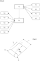
- FIG 1 very schematically represents the steps of a method according to the invention for manufacturing an annular casing for an aircraft turbine engine.
- This casing is for example a fan casing.
- the method essentially comprises two steps, namely a step a) of preparing a strip of preimpregnated fabric 10 ( figure 2 ), and a step b) of applying this strip 10 to the outer surface 14 of a body 12 of the casing ( figure 4 And 5 ).
- the first step a) of manufacturing the strip 10 can be divided into several successive sub-steps. It may comprise a first sub-step a1) of manufacturing the strip of fabric.
- a loom can for example be used to make the strip of fabric from fibers, preferably glass.
- the glass fibers form the weft and warp threads of the fabric and are intended to be oriented at 90° to each other and at approximately 45° with respect to an axis of elongation A of the strip, as is schematically illustrated in figure 2 .
- the band 10 has a width l and a length L and its length (largest dimension) extends along the axis of elongation A.
- the first step a) may include another sub-step a2) of impregnating the strip with a self-extinguishing resin which is for example the M26T ® resin marketed by Hexcel
- the first step a) may include another sub-step a3 ) provision of a protective film on each side of the strip.
- the strip 10 can be wound on itself or on an axis to form a roll 16 that is easier to handle ( figure 2 ).
- the second step b) can comprise several successive sub-steps.
- the first sub-step b1) consists in rotating the body 12 of the casing, as illustrated in picture 3 .
- the body 12 is made of a composite material based on a different resin from the impregnating resin of the strip.
- the resin of the body 12 is chosen for its mechanical properties and may be the CYCOM® PR 520 resin marketed by the company Solvay (formerly Cytec).
- the body 12 of the casing has a generally annular shape around an axis of revolution B and may include an annular fixing flange 18 at each of its axial ends.
- the body 12 of the housing is rotated by means of rollers at the picture 3 .
- the body 12 can be arranged on rollers 20 which rest on the outer surface 14 of the body.
- Rollers 20 can also be arranged inside the body and rest on an internal surface 22 of the body.
- the rollers 20 are motorized so as to control the speed of rotation of the casing body 12.
- the roll of tape 16 is placed next to the body 12 which is rotatable.
- the roller 16 is itself set in rotation (sub-step b2)) around its axis to unwind the strip 10 and apply it with a certain tension on the outer surface 14 of the body 12.
- the roller 16 is mounted on a motorized unwinder so as to control its rotation speed.
- the width l of the strip 10 is preferably greater than the width of the body 12. It is therefore understood that a single pass of the strip 10 all around the body 12 is sufficient to cover the entire the outer surface 14 of the body.
- the body 12 of the housing and the roller 16 rotate in opposite directions.
- the axis of the roller 16 is inclined by a first predetermined angle ⁇ with respect to a horizontal plane passing through the axis B and by a second predetermined angle ⁇ with respect to a vertical plane passing through this axis B.
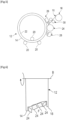
- the compacting rollers 24 extend along the axis B and have profiles complementary to the relief of the outer surface 14 of the body 12 ( figure 6 ).
- the pressures F exerted by the rollers 24 on the strip 10 and the body 12 are preferably managed and adjusted independently of each other (sub-step b3)).
- the compaction rollers 24 each include at least one outer annular layer of foam.
- the foam layers of at least some of the rolls 24 preferably have different stiffnesses.
- the foams allow the rollers 24 to adapt to the changing shape of the body 12 and the resulting deframing rate. They are for example in the shape of the spokes of the flanges 18 at the two ends of the body 12 in order to allow the draping in the bottom of the spokes of these flanges.
- the tension parameters of the strip 10 and the contact pressure of the compacting rollers 24 can be controlled.
- Infrared lamps 26, 28 are arranged upstream and downstream of the compacting rollers, with respect to the winding direction of the strip 10 on the body 12.
- the upstream lamp 26 makes it possible to heat the strip 10 before its installation and the downstream lamp 28 makes it possible to simultaneously heat the strip 10 and the body 12. This facilitates the adhesion of the strip to the outer surface 14 of the body 12 (sub-step b4)).
- Film reels 30 are arranged under and on the strip 10 during its unwinding. These unwinders 30 are configured to remove the protective films present on both sides of the strip, before it is applied to the body 12 of the casing (sub-step b5)).
Landscapes
- Engineering & Computer Science (AREA)
- Mechanical Engineering (AREA)
- Chemical & Material Sciences (AREA)
- Composite Materials (AREA)
- Textile Engineering (AREA)
- Physics & Mathematics (AREA)
- Mathematical Physics (AREA)
- Moulding By Coating Moulds (AREA)
- Structures Of Non-Positive Displacement Pumps (AREA)
Description
- La présente invention concerne un procédé de fabrication d'un carter annulaire pour une turbomachine d'aéronef.
- L'arrière-plan technique comprend notamment les documents
US-A1-2015/239181 ,US-A1 -2009/098337 etWO-A1-2019/013239 . - Le document
US2009/022579 A1 décrit un article composite résistant aux brûlures comprenant au moins une couche composite comprenant des premières fibres dans une première matrice de résine organique, la couche composite ayant une première résistance thermique ; et au moins une couche de résistance à la combustion adjacente à la au moins une couche composite et comprenant des secondes fibres dans une seconde matrice de résine organique, la couche de résistance à la combustion ayant une seconde résistance thermique qui est supérieure à la première résistance thermique de la couche composite. - Une turbomachine d'aéronef comprend plusieurs carters annulaires. Pour alléger un carter, il est connu de le réaliser dans un matériau composite. Dans la présente demande, on entend par matériau composite, un matériau comportant des charges telles que des fibres noyées dans une matrice polymérique. La matrice polymérique est en général une résine.
- Un carter de soufflante peut par exemple être réalisé en matériau composite. Ce carter entoure la soufflante de la turbomachine et doit répondre à un cahier des charges nécessaire à sa certification notamment en ce qui concerne sa tenue au feu.
- La résine utilisée pour la fabrication du carter de soufflante est choisie pour ses propriétés mécaniques mais est inflammable dans la technique actuelle et il est donc nécessaire de recouvrir la surface supérieure du carter d'une couche anti-feu.
- Des solutions existent mais ne sont pas entièrement satisfaisantes en particulier car elles sont longues et complexes à mettre en oeuvre.
- L'invention propose de remédier à cet inconvénient.
- L'invention propose ainsi un procédé de fabrication d'un carter annulaire pour une turbomachine d'aéronef, ce carter comportant un corps annulaire en matériau composite à base d'une première résine, et une couche externe anti-feu qui recouvre une surface annulaire externe du corps et qui est réalisée en matériau composite à base d'une seconde résine auto-extinguible, caractérisé en ce qu'il comprend :
- a) une étape de préparation d'une bande d'un tissu préimprégnée avec ladite seconde résine, cette bande ayant une forme allongée le long d'un axe d'allongement et une largeur au moins égale et de préférence supérieure à une largeur dudit corps mesurée le long de son axe de révolution, cette bande comportant des fibres tissées et orientées dans des directions perpendiculaires entre elles et inclinées d'un angle de 45° environ par rapport audit axe d'allongement, et
- b) une étape d'application de la bande sur la surface externe du corps, de façon à recouvrir l'intégralité de cette surface en une seule passe de la bande autour du corps.
- L'invention propose d'utiliser une résine auto-extinguible et de préimprégner une bande de tissu avec cette résine qui est ensuite déposée tout autour du corps du carter.
- La bande est réalisée par tissage de fibres de verre ou carbone par exemple. Ces fibres sont orientées dans des directions particulières qui vont faciliter le décadrage de la bande lors de sa pose sur le corps.
- En effet, la surface extérieure du corps du carter peut avoir un relief marqué. Lors de l'application de la bande, il est important que cette bande épouse ce relief sans créer de bulles d'air par exemple. Les fibres orientées à 90° les unes des autres et à 45° de l'axe d'allongement de la bande vont pouvoir plus facilement glisser les unes sur les autres et faciliter le décadrage de la bande. Le corps est avantageusement entouré par une unique bande. Cette bande s'étend sur tout le pourtour du corps et a une largeur au moins égale à celle du corps.
- L'invention permet en outre de lutter contre la corrosion galvanique du carter lorsqu'il est réalisé dans un assemblage composite / métallique.
- Le procédé selon l'invention peut comprendre une ou plusieurs des caractéristiques suivantes, prises indépendamment les unes des autres ou en combinaison les unes avec les autres :
- la bande est enroulée et se présente sous la forme d'un rouleau à la fin de l'étape a), ce rouleau étant disposé sur un côté du corps à l'étape b), et le corps et le rouleau étant mis en rotation autour de leurs axes respectifs pendant l'étape b) ;
- le corps est mis en rotation à l'étape b) par l'intermédiaire de galets prenant appui sur la surface externe et/ou sur une surface interne du corps ;
- à l'étape b), l'axe de rotation du rouleau est incliné d'un angle prédéterminé par rapport à au moins un plan passant par l'axe de révolution du corps ;
- à l'étape b), au moins un rouleau de compactage est utilisé pour appliquer la bande sur la surface externe du corps ;
Procédé selon la revendication 5, dans lequel plusieurs rouleaux de compactage sont répartis le long de l'axe de révolution du corps et ont des profils complémentaires au relief de la surface externe du corps ; - les rouleaux de compactage comprennent chacun au moins une couche annulaire externe de mousse, les couches de mousse d'au moins certains des rouleaux ayant des rigidités différentes. ;
- à l'étape b), des paramètres sont asservis et comprennent une tension de la bande dans ladite direction, et une pression de contact de la ou de chaque rouleau de compactage ;
- des éléments chauffants, tels que des lampes infrarouge, des torches plasma ou laser, etc., sont disposés en amont et en aval dudit au moins un rouleau de compactage, par rapport au sens d'enroulement de la bande sur le corps ;
- des dévideurs de films sont disposés sous et sur la bande lors de son déroulement, ces dévideurs étant configurés pour retirer des films de protection présents sur les deux faces de la bande.
- D'autres caractéristiques et avantages de l'invention apparaitront au cours de la lecture de la description détaillée qui va suivre pour la compréhension de laquelle on se reportera aux dessins annexés dans lesquels :
- [
Fig. 1 ] lafigure 1 est un organigramme montrant des étapes d'un procédé selon l'invention, - [
Fig. 2 ] lafigure 2 est une vue très schématique en perspective d'une bande de tissu préimprégné utilisée dans le procédé selon l'invention, - [
Fig. 3 ] lafigure 3 est une vue très schématique en perspective d'un corps de carter et de galets de mise en rotation de ce corps, pour la mise en oeuvre du procédé selon l'invention, - [
Fig. 4 ] lafigure 4 illustre de manière schématique une étape du procédé selon l'invention, - [
Fig. 5 ] lafigure 5 illustre de manière schématique l'étape du procédé de lafigure 4 , et - [
Fig. 6 ] lafigure 6 est une vue très schématique partielle en coupe axiale d'un carter et de rouleaux de compactage, pour la mise en oeuvre du procédé selon l'invention. - La
figure 1 représente de manière très schématique des étapes d'un procédé selon l'invention de fabrication d'un carter annulaire pour une turbomachine d'aéronef. - Ce carter est par exemple un carter de soufflante.
- Le procédé comprend pour l'essentiel deux étapes, à savoir une étape a) de préparation d'une bande de tissu préimprégné 10 (
figure 2 ), et une étape b) d'application de cette bande 10 sur la surface externe 14 d'un corps 12 du carter (figures 4 et5 ). - La première étape a) de fabrication de la bande 10 peut être divisée en plusieurs sous étapes successives. Elle peut comprendre une première sous étape a1) de fabrication de la bande de tissu. Pour cela, un métier à tisser peut par exemple être utilisé pour réaliser la bande de tissu à partir de fibres, de préférence de verre. Les fibres de verre forment des fils de trame et de chaîne du tissu et sont destinées à être orientées à 90° l'une de l'autre et à 45° environ par rapport à un axe d'allongement A de la bande, comme cela est schématiquement illustré à la
figure 2 . - La bande 10 a une largeur ℓ et une longueur L et sa longueur (plus grande dimension) s'étend le long de l'axe d'allongement A.
- La première étape a) peut comprendre une autre sous étape a2) d'imprégnation de la bande avec une résine auto-extinguible qui est par exemple la résine M26T® commercialisée par la société Hexcel La première étape a) peut comprendre une autre sous étape a3) de disposition d'un film de protection sur chacune des faces de la bande. Enfin, lors d'une autre sous-étape a4), la bande 10 peut être enroulée sur elle-même ou sur un axe pour former un rouleau 16 plus facile à manipuler (
figure 2 ). - De la même façon, la deuxième étape b) peut comprendre plusieurs sous-étapes successives.
- La première sous-étape b1) consiste à mettre en rotation le corps 12 du carter, comme illustré à la
figure 3 . Le corps 12 est en matériau composite à base d'une résine différente de la résine d'imprégnation de la bande. La résine du corps 12 est choisie pour ses propriétés mécaniques et peut être la résine CYCOM® PR 520 commercialisée par la société Solvay (anciennement Cytec). - Le corps 12 du carter a une forme générale annulaire autour d'un axe de révolution B et peut comprendre une bride annulaire 18 de fixation à chacune de ses extrémités axiales.
- Le corps 12 du carter est mis en rotation par l'intermédiaire de galets à la
figure 3 . Pour cela le corps 12 peut être disposé sur des galets 20 qui prennent appui sur la surface externe 14 du corps. Des galets 20 peuvent en outre être disposés à l'intérieur du corps et prendre appui sur une surface interne 22 du corps. Les galets 20 sont motorisés de façon à asservir la vitesse de rotation du corps de carter 12. - Dans la présente demande, on entend par les expressions interne et externe ou intérieure ou extérieure des positions par rapport à l'axe B de révolution du carter ou de son corps 14.
- Lors de la deuxième étape b), le rouleau de bande 16 est disposé à côté du corps 12 mobile en rotation. Le rouleau 16 est lui-même mis en rotation (sous-étape b2)) autour de son axe pour dérouler la bande 10 et l'appliquer avec une certaine tension sur la surface externe 14 du corps 12. Le rouleau 16 est monté sur un dérouleur motorisé de façon à asservir sa vitesse de rotation.
- Comme on le voit dans les dessins, la largeur ℓ de la bande 10 est de préférence supérieure à la largeur du corps 12. On comprend donc qu'une seul passe de la bande 10 tout autour du corps 12 suffit à recouvrir l'intégralité de la surface externe 14 du corps.
- Dans l'exemple représenté, le corps 12 du carter et le rouleau 16 tournent dans des sens contraires.
- Dans l'exemple représenté à la
figure 4 , l'axe du rouleau 16 est incliné d'un premier angle α prédéterminé par rapport à un plan horizontal passant par l'axe B et d'un second angle β prédéterminé par rapport à un plan vertical passant par cet axe B. - La
figure 4 permet en outre de voir que cette inclinaison permet par exemple d'accentuer la tension de la bande 10 sur un côté, par exemple le côté amont du carter, par rapport au côté aval, afin de faciliter le décadrage de la bande. La bande 10 déroulée s'étend depuis le rouleau 16 jusqu'à la surface externe 14 du corps 12 du carter et elle est appliquée sur cette surface en exerçant une pression au moyen de rouleaux de compactage 24. - Avantageusement, les rouleaux de compactage 24 s'étendent le long de l'axe B et ont des profils complémentaires au relief de la surface externe 14 du corps 12 (
figure 6 ). - Les pressions F exercées par les rouleaux 24 sur la bande 10 et le corps 12 sont de préférence gérées et réglées indépendamment les unes des autres (sous-étape b3)). Les rouleaux de compactage 24 comprennent chacun au moins une couche annulaire externe de mousse. Les couches de mousse d'au moins certains des rouleaux 24 ont de préférence des rigidités différentes. Les mousses permettent aux rouleaux 24 de s'adapter à la forme évolutive du corps 12 et au taux de décadrage résultant. Ils sont par exemple à la forme des rayons des brides 18 aux deux extrémités du corps 12 afin de permettre le drapage dans le fond des rayons de ces brides.
- Les paramètres de tension de la bande 10 et de pression de contact des rouleaux de compactage 24 peuvent être asservis.
- Des lampes infrarouges 26, 28 sont disposées en amont et en aval des rouleaux de compactage, par rapport au sens d'enroulement de la bande 10 sur le corps 12. La lampe amont 26 permet de chauffer la bande 10 avant sa pose et la lampe aval 28 permet de chauffer simultanément la bande 10 et le corps 12. Ceci permet de faciliter l'adhésion de la bande sur la surface externe 14 du corps 12 (sous-étape b4)).
- Des dévideurs 30 de films sont disposés sous et sur la bande 10 lors de son déroulement. Ces dévideurs 30 sont configurés pour retirer les films de protection présents sur les deux faces de la bande, avant son application sur le corps 12 du carter (sous-étape b5)).
Claims (10)
- Procédé de fabrication d'un carter annulaire pour une turbomachine d'aéronef, ce carter comportant un corps annulaire (12) en matériau composite à base d'une première résine, et une couche externe anti-feu qui recouvre une surface annulaire externe (14) du corps et qui est réalisée en matériau composite à base d'une seconde résine auto-extinguible, tel qu'il comprend :a) une étape de préparation d'une bande (10) d'un tissu préimprégnée avec ladite seconde résine, cette bande ayant une forme allongée le long d'un axe d'allongement (A) et une largeur (e) au moins égale et de préférence supérieure à une largeur dudit corps mesurée le long de son axe de révolution (B), cette bande comportant des fibres tissées et orientées dans des directions perpendiculaires entre elles et inclinées d'un angle de 45° environ par rapport audit axe d'allongement, etb) une étape d'application de la bande sur la surface externe du corps, de façon à recouvrir l'intégralité de cette surface en une seule passe de la bande autour du corps.
- Procédé selon la revendication 1, dans lequel la bande (10) est enroulée et se présente sous la forme d'un rouleau (16) à la fin de l'étape a), ce rouleau étant disposé sur un côté du corps (12) à l'étape b), et le corps et le rouleau étant mis en rotation autour de leurs axes respectifs pendant l'étape b).
- Procédé selon la revendication 2, dans lequel le corps (12) est mis en rotation à l'étape b) par l'intermédiaire de galets (20) prenant appui sur la surface externe (14) et/ou sur une surface interne (22) du corps.
- Procédé selon la revendication 2 ou 3, dans lequel, à l'étape b), l'axe de rotation du rouleau (16) est incliné d'un angle (α, β) prédéterminé par rapport à au moins un plan passant par l'axe (B) de révolution du corps.
- Procédé selon l'une des revendications précédentes, dans lequel, à l'étape b), au moins un rouleau de compactage (24) est utilisé pour appliquer la bande (10) sur la surface externe (14) du corps (12).
- Procédé selon la revendication 5, dans lequel plusieurs rouleaux de compactage (24) sont répartis le long de l'axe (B) de révolution du corps (12) et ont des profils complémentaires au relief de la surface externe (14) du corps.
- Procédé selon la revendication 6, dans lequel les rouleaux de compactage (24) comprennent chacun au moins une couche annulaire externe de mousse, les couches de mousse d'au moins certains des rouleaux ayant des rigidités différentes.
- Procédé selon l'une des revendications 5 à 7, dans lequel, à l'étape b), des paramètres sont asservis et comprennent une tension de la bande (10) dans ladite direction, et une pression de contact de la ou de chaque rouleau de compactage (24).
- Procédé selon l'une des revendications 5 à 8, dans lequel des éléments chauffants, tels que des lampes infrarouge (26, 28), sont disposés en amont et en aval dudit au moins un rouleau de compactage (24), par rapport au sens d'enroulement de la bande (10) sur le corps (12).
- Procédé selon l'une des revendications précédentes, dans lequel des dévideurs de films (30) sont disposés sous et sur la bande (10) lors de son déroulement, ces dévideurs étant configurés pour retirer des films de protection présents sur les deux faces de la bande.
Applications Claiming Priority (2)
| Application Number | Priority Date | Filing Date | Title |
|---|---|---|---|
| FR1909462A FR3100152B1 (fr) | 2019-08-28 | 2019-08-28 | Procede de fabrication d’un carter annulaire pour une turbomachine d’aeronef |
| PCT/FR2020/051493 WO2021038164A1 (fr) | 2019-08-28 | 2020-08-24 | Procede de fabrication d'un carter annulaire pour une turbomachine d'aeronef |
Publications (2)
| Publication Number | Publication Date |
|---|---|
| EP4021708A1 EP4021708A1 (fr) | 2022-07-06 |
| EP4021708B1 true EP4021708B1 (fr) | 2023-06-21 |
Family
ID=68807088
Family Applications (1)
| Application Number | Title | Priority Date | Filing Date |
|---|---|---|---|
| EP20775038.1A Active EP4021708B1 (fr) | 2019-08-28 | 2020-08-24 | Procede de fabrication d'un carter annulaire pour une turbomachine d'aeronef |
Country Status (5)
| Country | Link |
|---|---|
| US (1) | US11826968B2 (fr) |
| EP (1) | EP4021708B1 (fr) |
| CN (1) | CN114340881B (fr) |
| FR (1) | FR3100152B1 (fr) |
| WO (1) | WO2021038164A1 (fr) |
Families Citing this family (2)
| Publication number | Priority date | Publication date | Assignee | Title |
|---|---|---|---|---|
| US20230013205A1 (en) * | 2021-07-14 | 2023-01-19 | Raytheon Technologies Corporation | Method of fabric processing for improved cmc infiltration |
| FR3128658B1 (fr) * | 2021-11-04 | 2023-11-03 | Safran Aircraft Engines | Fabrication d’une préforme d’une partie d’aube ou d’hélice par enroulement d’une texture obtenue par tissage en forme |
Family Cites Families (15)
| Publication number | Priority date | Publication date | Assignee | Title |
|---|---|---|---|---|
| EP0392348A3 (fr) * | 1989-04-14 | 1991-12-27 | Cytec Technology Corp. | Matériaux de construction tenaces et thermodurcissables |
| US20080160122A1 (en) * | 2006-12-28 | 2008-07-03 | Lee Alan Blanton | Continuous debulking systems |
| US20090022579A1 (en) * | 2007-07-17 | 2009-01-22 | Schlichting Kevin W | Burn resistant organic matrix composite material |
| US9017814B2 (en) | 2007-10-16 | 2015-04-28 | General Electric Company | Substantially cylindrical composite articles and fan casings |
| US7905972B2 (en) * | 2007-10-16 | 2011-03-15 | General Electric Company | Methods for making substantially cylindrical articles and fan casings |
| FR2928294B1 (fr) * | 2008-03-07 | 2016-12-30 | Duqueine Rhone Alpes | Procede et dispositif de realisation d'un profil courbe en materiau composite,et profil correspondant. |
| US8282757B2 (en) * | 2009-11-10 | 2012-10-09 | Alliant Techsystems Inc. | Automated composite annular structure forming |
| FR2995555B1 (fr) * | 2012-09-17 | 2017-11-24 | Snecma | Machine d'enroulement d'une texture fibreuse permettant un controle d'alignement et de decadrage par analyse d'image |
| FR3016187B1 (fr) * | 2014-01-09 | 2016-01-01 | Snecma | Protection contre le feu d'un carter de soufflante en materiau composite |
| FR3016188B1 (fr) * | 2014-01-09 | 2016-01-01 | Snecma | Protection contre le feu d'une piece en materiau composite tisse tridimensionnel |
| FR3037511B1 (fr) * | 2015-06-18 | 2017-06-02 | Snecma | Dispositif de revetement d'un carter annulaire de turbomachine |
| FR3046746B1 (fr) * | 2016-01-15 | 2018-02-09 | Safran Aircraft Engines | Dispositif de guidage d'une texture fibreuse sur un mandrin d'impregnation, et mandrin d'impregnation et machine d'enroulement associes |
| WO2019013239A1 (fr) * | 2017-07-11 | 2019-01-17 | 日立金属株式会社 | Roue de véhicule |
| BE1025628B1 (fr) * | 2017-10-09 | 2019-05-09 | Safran Aero Boosters S.A. | Procédé de fabrication de carter composite de compresseur pour turbomachine |
| FR3074081B1 (fr) * | 2017-11-29 | 2020-12-25 | Arianegroup Sas | Procede et installation de bobinage d'une bande de tissu pre-impregnee sur une surface inclinee |
-
2019
- 2019-08-28 FR FR1909462A patent/FR3100152B1/fr not_active Expired - Fee Related
-
2020
- 2020-08-24 CN CN202080059924.2A patent/CN114340881B/zh active Active
- 2020-08-24 EP EP20775038.1A patent/EP4021708B1/fr active Active
- 2020-08-24 WO PCT/FR2020/051493 patent/WO2021038164A1/fr not_active Ceased
- 2020-08-24 US US17/637,122 patent/US11826968B2/en active Active
Also Published As
| Publication number | Publication date |
|---|---|
| FR3100152A1 (fr) | 2021-03-05 |
| EP4021708A1 (fr) | 2022-07-06 |
| US11826968B2 (en) | 2023-11-28 |
| US20220339889A1 (en) | 2022-10-27 |
| CN114340881A (zh) | 2022-04-12 |
| CN114340881B (zh) | 2024-04-16 |
| FR3100152B1 (fr) | 2021-07-23 |
| WO2021038164A1 (fr) | 2021-03-04 |
Similar Documents
| Publication | Publication Date | Title |
|---|---|---|
| EP2454081B1 (fr) | Machine d'application de fibres comprenant un rouleau de compactage souple avec systeme de regulation thermique | |
| EP1123194B1 (fr) | Procede de fabrication d'un corps de revolution creux, corps tel qu'obtenu par ledit procede, et dispositif de mise en oeuvre dudit procede | |
| EP4021708B1 (fr) | Procede de fabrication d'un carter annulaire pour une turbomachine d'aeronef | |
| EP2697038B1 (fr) | Machine d'enroulement d'une texture fibreuse sur un mandrin d'impregnation et utilisation d'une telle machine pour la realisation d'un carter de turbine a gaz en materiau composite | |
| EP2262634A2 (fr) | Procédé et dispositif de réalisation d'un profil courbe en matériau composite, et profil correspondant | |
| EP2763841A1 (fr) | Dispositif et methode pour la fabrication d'une piece en materiau composite | |
| EP1419337A1 (fr) | Ruban textile plat de renfort pour conduite et conduite ainsi renforcee | |
| WO2016156677A1 (fr) | Tête d'application de fibres avec rouleau d'application particulier | |
| EP3500413B1 (fr) | Installation et procede de mise en forme d'une preforme fibreuse de revolution presentant en section radiale un profil evolutif | |
| EP3541600B1 (fr) | Machine et procédé pour la pose simultanée et en hélice de câbles sur la surface externe d'un élément unitaire de conduite de transport de fluides | |
| EP2331316B1 (fr) | Méthode et installation de construction d'une couche de fils d'armure | |
| WO1992005383A1 (fr) | Procede pour reparer ou restaurer sur place un tronçon d'une canalisation ou d'une enceinte destinee a contenir ou contenant un fluide sous pressions, et dispositif pour la mise en ×uvre de ce procede | |
| EP3402657B1 (fr) | Dispositif de guidage d'une texture fibreuse sur un mandrin d'imprégnation, et mandrin d'imprégnation et machine d'enroulement associés | |
| WO2017089659A1 (fr) | Tete d'application de fibres avec rouleau souple muni d'une couche exterieure metallique | |
| EP3162533B1 (fr) | Installation pour la fabrication d'un revêtement de protection thermique d'un corps ou d'un ensemble arrière de propulseur et procédés associés | |
| FR3059988B1 (fr) | Procede et machine pour l'enroulement d'un element filaire autour d'une piece pour le frettage, l'enroulement filamentaire ou le marouflage | |
| EP1608499B1 (fr) | Dispositif d'etirage longitudinal de films | |
| FR2850368A1 (fr) | Procede de depose sur un support de couches fibreuses successives inclinees, a partir d'une bande continue | |
| EP3019328A2 (fr) | Roue de guidage pour les ensembles de pose de couches de fils d'armure et methode de montage associee | |
| EP1574319B1 (fr) | Procédé d'enroulement d'un ruban composite et son dispositif de mise en oeuvre | |
| EP4285044A1 (fr) | Conduite flexible de transport de fluide et procédé de fabrication associé | |
| FR3019487A1 (fr) | Procede et installation de fabrication de films a bulles | |
| WO2025003614A1 (fr) | Installation pour l'assemblage d'une ame d'un panneau et procede associe | |
| FR3167332A1 (fr) | Procede de fabrication d’une structure alveolaire pour une piece en particulier d’une turbomachine d’aeronef | |
| FR2659933A1 (fr) | Systeme de reprise de contraintes longitudinales a l'extremite d'une structure souple, et son procede de fabrication. |
Legal Events
| Date | Code | Title | Description |
|---|---|---|---|
| STAA | Information on the status of an ep patent application or granted ep patent |
Free format text: STATUS: UNKNOWN |
|
| STAA | Information on the status of an ep patent application or granted ep patent |
Free format text: STATUS: THE INTERNATIONAL PUBLICATION HAS BEEN MADE |
|
| PUAI | Public reference made under article 153(3) epc to a published international application that has entered the european phase |
Free format text: ORIGINAL CODE: 0009012 |
|
| STAA | Information on the status of an ep patent application or granted ep patent |
Free format text: STATUS: REQUEST FOR EXAMINATION WAS MADE |
|
| 17P | Request for examination filed |
Effective date: 20220211 |
|
| AK | Designated contracting states |
Kind code of ref document: A1 Designated state(s): AL AT BE BG CH CY CZ DE DK EE ES FI FR GB GR HR HU IE IS IT LI LT LU LV MC MK MT NL NO PL PT RO RS SE SI SK SM TR |
|
| DAV | Request for validation of the european patent (deleted) | ||
| DAX | Request for extension of the european patent (deleted) | ||
| GRAP | Despatch of communication of intention to grant a patent |
Free format text: ORIGINAL CODE: EPIDOSNIGR1 |
|
| STAA | Information on the status of an ep patent application or granted ep patent |
Free format text: STATUS: GRANT OF PATENT IS INTENDED |
|
| RIC1 | Information provided on ipc code assigned before grant |
Ipc: B29C 70/00 20060101ALI20230302BHEP Ipc: B29C 53/56 20060101ALI20230302BHEP Ipc: F02C 7/25 20060101ALI20230302BHEP Ipc: F02C 7/04 20060101ALI20230302BHEP Ipc: F01D 21/04 20060101ALI20230302BHEP Ipc: B29L 31/30 20060101ALI20230302BHEP Ipc: B29C 35/08 20060101ALI20230302BHEP Ipc: B29L 31/00 20060101ALI20230302BHEP Ipc: B29C 53/60 20060101ALI20230302BHEP Ipc: B32B 27/12 20060101ALI20230302BHEP Ipc: B29C 70/32 20060101ALI20230302BHEP Ipc: B29C 70/22 20060101AFI20230302BHEP |
|
| INTG | Intention to grant announced |
Effective date: 20230331 |
|
| GRAS | Grant fee paid |
Free format text: ORIGINAL CODE: EPIDOSNIGR3 |
|
| GRAA | (expected) grant |
Free format text: ORIGINAL CODE: 0009210 |
|
| STAA | Information on the status of an ep patent application or granted ep patent |
Free format text: STATUS: THE PATENT HAS BEEN GRANTED |
|
| AK | Designated contracting states |
Kind code of ref document: B1 Designated state(s): AL AT BE BG CH CY CZ DE DK EE ES FI FR GB GR HR HU IE IS IT LI LT LU LV MC MK MT NL NO PL PT RO RS SE SI SK SM TR |
|
| REG | Reference to a national code |
Ref country code: CH Ref legal event code: EP |
|
| REG | Reference to a national code |
Ref country code: DE Ref legal event code: R096 Ref document number: 602020012832 Country of ref document: DE |
|
| REG | Reference to a national code |
Ref country code: AT Ref legal event code: REF Ref document number: 1580624 Country of ref document: AT Kind code of ref document: T Effective date: 20230715 |
|
| REG | Reference to a national code |
Ref country code: IE Ref legal event code: FG4D Free format text: LANGUAGE OF EP DOCUMENT: FRENCH |
|
| REG | Reference to a national code |
Ref country code: LT Ref legal event code: MG9D |
|
| REG | Reference to a national code |
Ref country code: NL Ref legal event code: MP Effective date: 20230621 |
|
| PG25 | Lapsed in a contracting state [announced via postgrant information from national office to epo] |
Ref country code: SE Free format text: LAPSE BECAUSE OF FAILURE TO SUBMIT A TRANSLATION OF THE DESCRIPTION OR TO PAY THE FEE WITHIN THE PRESCRIBED TIME-LIMIT Effective date: 20230621 Ref country code: NO Free format text: LAPSE BECAUSE OF FAILURE TO SUBMIT A TRANSLATION OF THE DESCRIPTION OR TO PAY THE FEE WITHIN THE PRESCRIBED TIME-LIMIT Effective date: 20230921 |
|
| REG | Reference to a national code |
Ref country code: AT Ref legal event code: MK05 Ref document number: 1580624 Country of ref document: AT Kind code of ref document: T Effective date: 20230621 |
|
| PG25 | Lapsed in a contracting state [announced via postgrant information from national office to epo] |
Ref country code: RS Free format text: LAPSE BECAUSE OF FAILURE TO SUBMIT A TRANSLATION OF THE DESCRIPTION OR TO PAY THE FEE WITHIN THE PRESCRIBED TIME-LIMIT Effective date: 20230621 Ref country code: NL Free format text: LAPSE BECAUSE OF FAILURE TO SUBMIT A TRANSLATION OF THE DESCRIPTION OR TO PAY THE FEE WITHIN THE PRESCRIBED TIME-LIMIT Effective date: 20230621 Ref country code: LV Free format text: LAPSE BECAUSE OF FAILURE TO SUBMIT A TRANSLATION OF THE DESCRIPTION OR TO PAY THE FEE WITHIN THE PRESCRIBED TIME-LIMIT Effective date: 20230621 Ref country code: LT Free format text: LAPSE BECAUSE OF FAILURE TO SUBMIT A TRANSLATION OF THE DESCRIPTION OR TO PAY THE FEE WITHIN THE PRESCRIBED TIME-LIMIT Effective date: 20230621 Ref country code: HR Free format text: LAPSE BECAUSE OF FAILURE TO SUBMIT A TRANSLATION OF THE DESCRIPTION OR TO PAY THE FEE WITHIN THE PRESCRIBED TIME-LIMIT Effective date: 20230621 Ref country code: GR Free format text: LAPSE BECAUSE OF FAILURE TO SUBMIT A TRANSLATION OF THE DESCRIPTION OR TO PAY THE FEE WITHIN THE PRESCRIBED TIME-LIMIT Effective date: 20230922 |
|
| PG25 | Lapsed in a contracting state [announced via postgrant information from national office to epo] |
Ref country code: FI Free format text: LAPSE BECAUSE OF FAILURE TO SUBMIT A TRANSLATION OF THE DESCRIPTION OR TO PAY THE FEE WITHIN THE PRESCRIBED TIME-LIMIT Effective date: 20230621 |
|
| PG25 | Lapsed in a contracting state [announced via postgrant information from national office to epo] |
Ref country code: SK Free format text: LAPSE BECAUSE OF FAILURE TO SUBMIT A TRANSLATION OF THE DESCRIPTION OR TO PAY THE FEE WITHIN THE PRESCRIBED TIME-LIMIT Effective date: 20230621 |
|
| PG25 | Lapsed in a contracting state [announced via postgrant information from national office to epo] |
Ref country code: ES Free format text: LAPSE BECAUSE OF FAILURE TO SUBMIT A TRANSLATION OF THE DESCRIPTION OR TO PAY THE FEE WITHIN THE PRESCRIBED TIME-LIMIT Effective date: 20230621 |
|
| PG25 | Lapsed in a contracting state [announced via postgrant information from national office to epo] |
Ref country code: IS Free format text: LAPSE BECAUSE OF FAILURE TO SUBMIT A TRANSLATION OF THE DESCRIPTION OR TO PAY THE FEE WITHIN THE PRESCRIBED TIME-LIMIT Effective date: 20231021 |
|
| PG25 | Lapsed in a contracting state [announced via postgrant information from national office to epo] |
Ref country code: SM Free format text: LAPSE BECAUSE OF FAILURE TO SUBMIT A TRANSLATION OF THE DESCRIPTION OR TO PAY THE FEE WITHIN THE PRESCRIBED TIME-LIMIT Effective date: 20230621 Ref country code: SK Free format text: LAPSE BECAUSE OF FAILURE TO SUBMIT A TRANSLATION OF THE DESCRIPTION OR TO PAY THE FEE WITHIN THE PRESCRIBED TIME-LIMIT Effective date: 20230621 Ref country code: RO Free format text: LAPSE BECAUSE OF FAILURE TO SUBMIT A TRANSLATION OF THE DESCRIPTION OR TO PAY THE FEE WITHIN THE PRESCRIBED TIME-LIMIT Effective date: 20230621 Ref country code: PT Free format text: LAPSE BECAUSE OF FAILURE TO SUBMIT A TRANSLATION OF THE DESCRIPTION OR TO PAY THE FEE WITHIN THE PRESCRIBED TIME-LIMIT Effective date: 20231023 Ref country code: IS Free format text: LAPSE BECAUSE OF FAILURE TO SUBMIT A TRANSLATION OF THE DESCRIPTION OR TO PAY THE FEE WITHIN THE PRESCRIBED TIME-LIMIT Effective date: 20231021 Ref country code: ES Free format text: LAPSE BECAUSE OF FAILURE TO SUBMIT A TRANSLATION OF THE DESCRIPTION OR TO PAY THE FEE WITHIN THE PRESCRIBED TIME-LIMIT Effective date: 20230621 Ref country code: EE Free format text: LAPSE BECAUSE OF FAILURE TO SUBMIT A TRANSLATION OF THE DESCRIPTION OR TO PAY THE FEE WITHIN THE PRESCRIBED TIME-LIMIT Effective date: 20230621 Ref country code: CZ Free format text: LAPSE BECAUSE OF FAILURE TO SUBMIT A TRANSLATION OF THE DESCRIPTION OR TO PAY THE FEE WITHIN THE PRESCRIBED TIME-LIMIT Effective date: 20230621 Ref country code: AT Free format text: LAPSE BECAUSE OF FAILURE TO SUBMIT A TRANSLATION OF THE DESCRIPTION OR TO PAY THE FEE WITHIN THE PRESCRIBED TIME-LIMIT Effective date: 20230621 |
|
| PG25 | Lapsed in a contracting state [announced via postgrant information from national office to epo] |
Ref country code: PL Free format text: LAPSE BECAUSE OF FAILURE TO SUBMIT A TRANSLATION OF THE DESCRIPTION OR TO PAY THE FEE WITHIN THE PRESCRIBED TIME-LIMIT Effective date: 20230621 |
|
| PG25 | Lapsed in a contracting state [announced via postgrant information from national office to epo] |
Ref country code: MC Free format text: LAPSE BECAUSE OF FAILURE TO SUBMIT A TRANSLATION OF THE DESCRIPTION OR TO PAY THE FEE WITHIN THE PRESCRIBED TIME-LIMIT Effective date: 20230621 |
|
| REG | Reference to a national code |
Ref country code: DE Ref legal event code: R097 Ref document number: 602020012832 Country of ref document: DE |
|
| REG | Reference to a national code |
Ref country code: CH Ref legal event code: PL |
|
| PG25 | Lapsed in a contracting state [announced via postgrant information from national office to epo] |
Ref country code: MC Free format text: LAPSE BECAUSE OF FAILURE TO SUBMIT A TRANSLATION OF THE DESCRIPTION OR TO PAY THE FEE WITHIN THE PRESCRIBED TIME-LIMIT Effective date: 20230621 |
|
| PG25 | Lapsed in a contracting state [announced via postgrant information from national office to epo] |
Ref country code: LU Free format text: LAPSE BECAUSE OF NON-PAYMENT OF DUE FEES Effective date: 20230824 |
|
| PLBE | No opposition filed within time limit |
Free format text: ORIGINAL CODE: 0009261 |
|
| STAA | Information on the status of an ep patent application or granted ep patent |
Free format text: STATUS: NO OPPOSITION FILED WITHIN TIME LIMIT |
|
| PG25 | Lapsed in a contracting state [announced via postgrant information from national office to epo] |
Ref country code: LU Free format text: LAPSE BECAUSE OF NON-PAYMENT OF DUE FEES Effective date: 20230824 Ref country code: DK Free format text: LAPSE BECAUSE OF FAILURE TO SUBMIT A TRANSLATION OF THE DESCRIPTION OR TO PAY THE FEE WITHIN THE PRESCRIBED TIME-LIMIT Effective date: 20230621 Ref country code: CH Free format text: LAPSE BECAUSE OF NON-PAYMENT OF DUE FEES Effective date: 20230831 |
|
| PG25 | Lapsed in a contracting state [announced via postgrant information from national office to epo] |
Ref country code: SI Free format text: LAPSE BECAUSE OF FAILURE TO SUBMIT A TRANSLATION OF THE DESCRIPTION OR TO PAY THE FEE WITHIN THE PRESCRIBED TIME-LIMIT Effective date: 20230621 |
|
| REG | Reference to a national code |
Ref country code: BE Ref legal event code: MM Effective date: 20230831 |
|
| REG | Reference to a national code |
Ref country code: IE Ref legal event code: MM4A |
|
| 26N | No opposition filed |
Effective date: 20240322 |
|
| PG25 | Lapsed in a contracting state [announced via postgrant information from national office to epo] |
Ref country code: SI Free format text: LAPSE BECAUSE OF FAILURE TO SUBMIT A TRANSLATION OF THE DESCRIPTION OR TO PAY THE FEE WITHIN THE PRESCRIBED TIME-LIMIT Effective date: 20230621 Ref country code: IT Free format text: LAPSE BECAUSE OF FAILURE TO SUBMIT A TRANSLATION OF THE DESCRIPTION OR TO PAY THE FEE WITHIN THE PRESCRIBED TIME-LIMIT Effective date: 20230621 |
|
| PG25 | Lapsed in a contracting state [announced via postgrant information from national office to epo] |
Ref country code: IE Free format text: LAPSE BECAUSE OF NON-PAYMENT OF DUE FEES Effective date: 20230824 |
|
| PG25 | Lapsed in a contracting state [announced via postgrant information from national office to epo] |
Ref country code: IE Free format text: LAPSE BECAUSE OF NON-PAYMENT OF DUE FEES Effective date: 20230824 |
|
| PG25 | Lapsed in a contracting state [announced via postgrant information from national office to epo] |
Ref country code: BE Free format text: LAPSE BECAUSE OF NON-PAYMENT OF DUE FEES Effective date: 20230831 |
|
| PG25 | Lapsed in a contracting state [announced via postgrant information from national office to epo] |
Ref country code: BG Free format text: LAPSE BECAUSE OF FAILURE TO SUBMIT A TRANSLATION OF THE DESCRIPTION OR TO PAY THE FEE WITHIN THE PRESCRIBED TIME-LIMIT Effective date: 20230621 |
|
| PG25 | Lapsed in a contracting state [announced via postgrant information from national office to epo] |
Ref country code: BG Free format text: LAPSE BECAUSE OF FAILURE TO SUBMIT A TRANSLATION OF THE DESCRIPTION OR TO PAY THE FEE WITHIN THE PRESCRIBED TIME-LIMIT Effective date: 20230621 |
|
| PG25 | Lapsed in a contracting state [announced via postgrant information from national office to epo] |
Ref country code: CY Free format text: LAPSE BECAUSE OF FAILURE TO SUBMIT A TRANSLATION OF THE DESCRIPTION OR TO PAY THE FEE WITHIN THE PRESCRIBED TIME-LIMIT; INVALID AB INITIO Effective date: 20200824 |
|
| PG25 | Lapsed in a contracting state [announced via postgrant information from national office to epo] |
Ref country code: HU Free format text: LAPSE BECAUSE OF FAILURE TO SUBMIT A TRANSLATION OF THE DESCRIPTION OR TO PAY THE FEE WITHIN THE PRESCRIBED TIME-LIMIT; INVALID AB INITIO Effective date: 20200824 |
|
| PGFP | Annual fee paid to national office [announced via postgrant information from national office to epo] |
Ref country code: DE Payment date: 20250819 Year of fee payment: 6 |
|
| PGFP | Annual fee paid to national office [announced via postgrant information from national office to epo] |
Ref country code: GB Payment date: 20250825 Year of fee payment: 6 |
|
| PGFP | Annual fee paid to national office [announced via postgrant information from national office to epo] |
Ref country code: FR Payment date: 20250821 Year of fee payment: 6 |
|
| PG25 | Lapsed in a contracting state [announced via postgrant information from national office to epo] |
Ref country code: TR Free format text: LAPSE BECAUSE OF FAILURE TO SUBMIT A TRANSLATION OF THE DESCRIPTION OR TO PAY THE FEE WITHIN THE PRESCRIBED TIME-LIMIT Effective date: 20230621 |